EP4046873A1 - Dispositif de support pour un véhicule automobile - Google Patents
Dispositif de support pour un véhicule automobile Download PDFInfo
- Publication number
- EP4046873A1 EP4046873A1 EP22157825.5A EP22157825A EP4046873A1 EP 4046873 A1 EP4046873 A1 EP 4046873A1 EP 22157825 A EP22157825 A EP 22157825A EP 4046873 A1 EP4046873 A1 EP 4046873A1
- Authority
- EP
- European Patent Office
- Prior art keywords
- carrier
- motor vehicle
- bicycle
- carrier device
- receiving
- Prior art date
- Legal status (The legal status is an assumption and is not a legal conclusion. Google has not performed a legal analysis and makes no representation as to the accuracy of the status listed.)
- Granted
Links
Images


Classifications
-
- B—PERFORMING OPERATIONS; TRANSPORTING
- B60—VEHICLES IN GENERAL
- B60R—VEHICLES, VEHICLE FITTINGS, OR VEHICLE PARTS, NOT OTHERWISE PROVIDED FOR
- B60R9/00—Supplementary fittings on vehicle exterior for carrying loads, e.g. luggage, sports gear or the like
- B60R9/08—Supplementary fittings on vehicle exterior for carrying loads, e.g. luggage, sports gear or the like specially adapted for sports gear
- B60R9/10—Supplementary fittings on vehicle exterior for carrying loads, e.g. luggage, sports gear or the like specially adapted for sports gear for cycles
-
- B—PERFORMING OPERATIONS; TRANSPORTING
- B60—VEHICLES IN GENERAL
- B60R—VEHICLES, VEHICLE FITTINGS, OR VEHICLE PARTS, NOT OTHERWISE PROVIDED FOR
- B60R9/00—Supplementary fittings on vehicle exterior for carrying loads, e.g. luggage, sports gear or the like
- B60R9/06—Supplementary fittings on vehicle exterior for carrying loads, e.g. luggage, sports gear or the like at vehicle front or rear
Definitions
- the present invention relates to a carrier device for a motor vehicle for fastening at least one bicycle with the features of the preamble of claim 1 and a motor vehicle with such a carrier device.
- Motor vehicles can be, for example, passenger cars, trucks or other vehicles for transporting people.
- passenger cars trucks or other vehicles for transporting people.
- the state of the art will be briefly outlined using passenger cars. The same applies in general to motor vehicles.
- Corresponding carrier devices are connected to the at least one fastening device, mostly in a rear area of the passenger vehicle on the bumper or underneath the vehicle.
- the connection can be made via a welded or screwed connection can be made, for example, on the chassis of the vehicle.
- the receiving device which is designed to receive the at least one bicycle, can then be pulled out of this lower or rear area along a direction of travel of the vehicle via the guide device, so that the carrier device is hidden in a stowed position in the rear area or below the vehicle and at Use can be converted into a use position on the guide device.
- Such well-known from the prior art support devices go for example from DE 102010017182 B1 , the DE 202015105297 U1 , the EP 1876059 A1 , the DE 202011109330 U1 , the DE 102004057649 A1 , the DE 10352644 A1 , the DE 19521886 A1 or the DE 202005012475 U1 out.
- a disadvantage of such carrier devices from the prior art is that the fastening device takes up a relatively wide and large area on the passenger vehicle and also requires a corresponding holder there, so that a fairly large area for attaching the carrier device has to be adapted or is lost on the vehicle side. which is required for vehicle components such as chassis, drive or exhaust system.
- the carrier device is in the rear area of the vehicle when it is in use fastening devices protruding at right angles (which are required, for example, to attach a bicycle to the frame via retaining claws) are provided, which in a stowed position impairs the free accessibility of the vehicle, so that in many cases, for example, the trunk can no longer be opened or is only accessible with difficulty.
- This usually makes it necessary to disassemble parts of the carrying device before the carrying device is transferred to a stowed position.
- the object of the present invention is to provide a carrier device and a motor vehicle with such a carrier device which at least partially improves the disadvantages of the prior art described above and/or increases user-friendliness and/or requires less space on the motor vehicle.
- a device according to the invention can also be used in already known design variants of the prior art, as also described, for example, by the introduction to the description, and can be installed subsequently.
- the at least one bicycle can be accommodated in the foldable accommodation device, for example with the crank locked between the frame and the crank of the bicycle.
- each holding device can be moved separately between the stowed position and at least one use position by tilting about the pull-out axis and/or by folding about an axis transverse to the pull-out axis.
- the tilting according to the invention of the at least one receiving element can be over an angle of more than 30°, preferably more than 60° and particularly preferably more than 80°. pass. In particularly preferred embodiments, the tilting can extend essentially over a 90° angle.
- an L-shaped configuration of the pull-out device can be undertaken, with the "L” being folded over during a transfer between the use position and the stowed position.
- the at least one receiving device is additionally connected to the at least one guide device such that it can be folded about a, preferably adjustable, transverse axis to the pull-out axis.
- the at least one receiving device can protrude from the guide device at a right angle in the use position and can rest against the guide device in the stowed position. As a result, even more space can be saved in the stowage position on or in the vehicle.
- the at least one receiving device can be converted into a use position by folding about an axis transverse to the pull-out axis, the at least one receiving device being secured by at least one locking device, preferably at least a stop which can be releasably locked against tilting in the use position.
- a U-shaped or V-shaped section can, for example, provide for the receiving device to have a U-shaped or V-shaped cutout, with a pedal or crank of the at least one bicycle being able to engage at the apex of the U-shaped or V-shaped cutout or can be attached to be transported with the carrier device can.
- this U- or V-shaped section points upwards, a particularly simple assembly of the at least one bicycle can thereby be made possible, the at least one bicycle being able to be lifted into the U- or V-shaped section only from above and thereby immediately is held without a assembling person having to continue holding the weight of the bicycle. Due to the arrangement of the carrier device according to the invention in or under a bumper, the at least one bicycle does not have to be lifted very high at the same time.
- the height of the at least one receiving device can be adjusted relative to the at least one fastening device in a mounted state on a motor vehicle.
- At least one detachable connecting device preferably at least one removable and/or foldable (and thus e.g. stowable) connecting tube, is provided for mounting the at least one clamping element on the at least one receiving device.
- At least one clamping element is foldable on the at least one receiving device, wherein the at least one clamping element can be folded onto the at least one bicycle in the use position and onto the at least one receiving device and/or others in the stowed position the at least one fastening device can be folded down.
- the connecting device includes a recess in which, for example, a tube or rod-like element can be fastened, on which the clamping element is arranged (for example, a holding claw).
- the at least one guiding device can contain tubes guided into one another.
- the outer or inner tube has a guide pin, which is guided, for example, in a guide link on the other tube, with the (e.g. L-shaped) guide link already guiding the pin between a stowed position and a use position, with one Rotational movement is included.
- the at least one guide rail or the at least one rolling body can be connected to the fastening device and/or receiving device in a motion-locked manner in the direction of the extension axis, with the receiving device being movable relative to the fastening device between the stowed position and the use position via a relative movement between the guide rail and rolling body.
- At least two guide rails and at least one rolling body arranged between the at least two guide rails, particularly preferably at least one rolling body are provided. Provision can be made for one of the at least two guide rails to be connected to the fastening device and the other of the at least two guide rails to be connected to the receiving device in a non-moving manner relative to the pull-out axis, with movement of the at least two guide rails relative to one another being permitted via the at least one rolling body (similar to a drawer slide) .
- At least one electrical connecting line is provided, which electrical connecting line is designed to To connect e-bike to a power source of the motor vehicle.
- the at least one receiving device can be locked in relation to the at least one fastening device by means of a locking device, preferably at least one clamping device, in the stowage position and/or in the at least one use position, preferably any use position.
- a locking device preferably at least one clamping device
- the at least one clamping device can, for example, have at least one clamping jaw, preferably actuated by an actuator, wherein by applying force to the at least one clamping jaw relative to a corresponding counterpart, the receiving device can be locked relative to the fastening device via a clamping force (and a resulting frictional force - similar to a shoe brake).
- the actuator for actuating the at least one clamping device can, for example, be designed to be electrically or hydraulically actuated.
- Such a locking device can also be provided, for example, by a bolt which allows movement of the guide device in the use or the Stowage position prevented.
- the locking is provided by the end positions of the guide device.
- the guide device includes a guide link--the end positions already bring about a locking between the fastening device and the receiving device.
- At least one drive is provided, wherein the at least one drive is designed to move the at least one receiving device between the stowed position and the at least one use position.
- the carrier device in particular the drive unit
- the at least one drive could be controlled via the operation of the motor vehicle in order to move the at least one receiving device between the stowed position and the at least one use position move.
- a license plate holder By arranging a license plate holder at the end of the at least one receiving device facing away from the fastening device, for example, a license plate can be moved with the carrier device and it is no longer necessary to remove it separately from the vehicle and to arrange it on a bicycle carrier. The same applies, of course, to the vehicle lighting or a warning device (such as a cat's eyes).
- Protection is also sought for a bicycle comprising at least one crank and/or at least one handlebar, the bicycle having at least one locking device, which at least one locking device is designed to prevent the crank and/or a handlebar of the at least one bicycle from twisting, preferably motionally rigid, to lock releasably.
- Protection is also sought for an arrangement of a carrier device according to the invention and at least one bicycle according to the invention.
- a motor vehicle with a carrier device according to the invention, the carrier device being connected to the motor vehicle, preferably to a chassis of the motor vehicle, via the at least one fastening device. Provision can preferably be made for the carrier device to be arranged in a rear area of the motor vehicle in the direction of travel, with the at least one receiving device being retracted into or under a bumper of the motor vehicle when the carrier device is in the stowed position and by the bumper of the motor vehicle in the at least one use position is spaced in the direction of travel.
- the carrier device can be integrated into the vehicle.
- FIG. 1 shows a first exemplary embodiment of a carrier device 1 according to the invention in a stowed position 17, the carrier device 1 being fastened to a motor vehicle 2 via its fastening device 4.
- the carrier device 1 is arranged in a rear area of the motor vehicle 2 in the direction of travel 16 .
- the receiving device 5 is retracted into a bumper of the motor vehicle 2 in a stowed position 17 of the carrier device 1 .
- the receiving device 5 can be moved between a stowed position 17 and a use position 18 via the guide device 6 of the carrier device 1, with the guide device 6 being designed in such a way that the receiving device 5 relative to the motor vehicle 2 along an extension axis 7 (which in this exemplary embodiment corresponds to the direction of travel 16 of the motor vehicle 2) is pulled out into a use position 18, wherein the receiving device 5 can be moved after being pulled out between the stowed position 17 and the use position 18 by tilting about the pull-out axis 7 (as indicated by the movement illustrated as an arrow in 1 can be seen) .
- the fastening device 4 of the carrier device 1 holds the carrier device 1 on the motor vehicle 2 and can be connected to the chassis of the motor vehicle 2 by screwing or welding.
- the receiving device 5 is designed to receive at least one bicycle 3, as will be explained in more detail in the following figures.
- the guide device 6 of this exemplary embodiment is formed by two tubes that are guided into one another, with the receiving device 5 being guided in relation to the fastening device 4 .
- the receiving device 5 By tilting the receiving device 5 about the pull-out axis 7 , the receiving device can be positioned in a use position 18 for receiving a bicycle 3 .
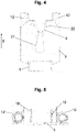
- FIG 2 shows a plan view of the embodiment of FIG 1 , wherein the carrier device 1 is located in 2 is in a use position 18 .
- the carrier device 1 also has two foldable signaling elements 20 which, in the use position 18 of the fastening device 4 , are provided on an end of the receiving device 5 which is remote from the motor vehicle 2 .
- These foldable signal elements 20 can be opened by 90° relative to the pull-out axis 7 (as indicated by the arrows) and carry the motor vehicle lighting 15 (for example indicators, rear lights or brake lights).
- a license plate holder 14 is provided on the end of the receiving device 5 facing away from the fastening device 4 and can be pulled out and opened together with the receiving device 5 via the guide device 6 relative to the fastening device 4 .
- the signal elements 20 can be folded onto the receiving device 5 when being transferred between the use position and the stowed position (as shown by the arrows) and together with this can be pushed into the rear area of the motor vehicle (or under the motor vehicle) so that they are in the stowed position 17 are hidden from a viewer.
- FIG. 3 shows a further exemplary embodiment of a carrier device 1 according to the invention, which is designed to accommodate a plurality of bicycles 3, with these bicycles 3 each being able to be accommodated on one of four receiving devices 5, with a total of four bicycles being able to be transported in this exemplary embodiment.
- the four receiving devices 5 are part of a common supporting structure which connects the receiving devices 5 to the guiding device 6 .
- each holding device 5 has connecting devices 12 which can hold clamping elements 10 for fastening the bicycles 3 (more details on this in the following figures).
- the carrier device 1 of this embodiment of the 3 has an electrical connecting line 13 .
- This electrical connecting line 13 is used to connect the motor vehicle lighting 15 to the lighting system of the motor vehicle 2 .
- this electrical connecting line 13 is used to provide a power source on the carrier device 1 for e-bikes, which is connected to the power source of the motor vehicle 2, so that e-bikes are charged via the carrier device 1 (e.g. during transport of the e-bike). can become.
- the receiving devices 5 of this exemplary embodiment can be locked in a stowage position 17 and a use position 18 by a locking device, whereby it can also be provided, for example, that several use positions 18 are provided, so that only one recording for a bicycle 3 protrudes from the rear of the motor vehicle. which is currently required for use.
- the locking can be effected, for example, by a bolt, which inhibits a movement of the guide device 6 by passing through the tubes guided into one another through correspondingly arranged bores and thus inhibiting a movement between the receiving device 5 and the fastening device 4 .
- a drive is provided, which drive moves the receiving device between a stowed position 17 and a use position 18 .
- This drive can also be used as a locking device if it is blocked.
- the guide device it is also conceivable for the guide device to have a guide link 25, in which a guide pin 26 is guided, with locking positions being provided at the end positions (or also in intermediate positions) of the guide link 25, so that the receiving device 5 is in a use position 18 and a stowed position 17 can be locked.
- this carrier device 1 for example license plate holder 14, motor vehicle lighting 15 or signal elements 20
- This carrier device 1 for example license plate holder 14, motor vehicle lighting 15 or signal elements 20
- 4 shows in more detail an example of a receiving device 5 for receiving a bicycle 3, wherein 4 represents a view along the extraction axis 7 of the carrier device 1 and figure 5 a top view of the 4 .
- This receiving device 5 is welded onto the guide device 6 of the carrier device 1 and extends at right angles to it.
- the receiving device 5 is designed to be foldable relative to the guide device 6 (e.g. by means of hinges), so that the receiving device 5 can also be folded over about an axis transverse to the extension axis 7 between the use position 18 and the stowed position 17, with the Recording device 5 in the use position 18 protrudes from the guide device 6 at a right angle and rests against the guide device 6 in the stowed position 17 .
- the receiving device 5 is designed to be foldable relative to the guide device 6 (e.g. by means of hinges), so that the receiving device 5 can also be folded over about an axis transverse to the extension axis 7 between the use position 18 and the stowed position 17, with the Recording device 5 in the use position 18 protrudes from the guide device 6 at a right angle and rests against the guide device 6 in the stowed position 17 .
- the receiving device 5 has a V-shaped section 9 .
- the V-shaped section 9 is designed to receive a pedal and/or a crank 21 of a bicycle 3 (as indicated in Fig 4 broken-line crank 21 of a bicycle 3 is indicated).
- the bicycle 3 has a locking mechanism which allows the position of the crank 21 to be locked relative to the bicycle 3, so that the position of the bicycle 3 relative to the carrier device 1 is secured by fastening the crank 21 to the receiving device 5 of the carrier device 1 can.
- clamping elements 10 for fastening the bicycle 3.
- These clamping elements 10 can be attached to the connecting devices 12 of the receiving device 5, as shown below 6 is evident.
- This crank 21 of the bicycle 3 can be blocked, for example, via a locking device 22 shown in dashed lines, and secure the bicycle 3 against theft.
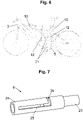
- FIG. 6 shows a carrier device 1 in use, with the receiving device 5 receiving a bicycle 3 .
- the bicycle 3 is inserted with the crank 21 into the V-shaped section 9 of the longitudinal extent 8, with the other crank 21 of the bicycle 3 finding its place in a recess in the guide device 6/receiving device 5 (see also 3 ).
- clamping elements 10 which are attached to the receiving device 5 by means of the connecting devices 12, the bicycle 3 can be additionally clamped, so that the bicycle 3 is secured in its position relative to the carrier device 1.
- the clamping elements are designed as retaining claws.
- the connecting devices 12 of the receiving device 5 have connecting tubes or connecting rods, which can be inserted into tube-like recesses and can be held in these recesses by clamping and/or providing a guide or locking link.
- FIG. 7 shows an embodiment of a guide device 6 of a carrier device 1 according to the invention, wherein the guide device 6 has two tubes 23, 24 guided inside one another.
- the inner tube 23 has a guide pin 26 which is positively connected to the inner tube 23 .
- the inner tube 23 can also be designed, for example, as a shaft or journal (solid component).
- the guide pin 26 of the inner tube 23 is guided in the slotted guide 25 of the outer tube 24 .
- the guide device 6 shown is in a use position 18.
- the guide link 25 shows how, starting from the usage position 18, the inner tube 23 must first be tilted by tilting about the extension axis 7 in order to then be able to be transferred along the extension axis into a stowed position 17.
- the guide pin 26 is in contact with the respective end positions of the guide link 25, as a result of which it can be locked in the respective position.
- the inner tube 23 can be connected to the fastening device 4 and the outer tube 24 to the receiving device 5.
- FIG. 8 shows a second exemplary embodiment of a carrier device 1 in a stowed position 17, the carrier device 1 being fastened to a motor vehicle 2 via its fastening device 4.
- the carrier device 1 of the variant of the 8 be moved by means of the guide device 6 between a stowed position and a use position in addition by flaps about a transverse axis transverse to the pull-out axis, as in the following by the figures 9 and 10 to be explained in greater detail.
- the receiving device 5 can be folded across from the guide device 6 via the hinge 27 transversely to the pull-out axis 7 and can thus be transferred between a use position 18 and a stowed position 17 .
- a pull-out movement along the pull-out axis 7 into a usage position 18 is kinematically coupled to the folding movement of the receiving device transverse to the pulling-out axis 7, so that the pulling-out movement can also automatically unfold the receiving device 5 (this applies of course also vice versa for the insertion movement into a stowage position 19).
- Such a kinematic coupling of the movements can be carried out, for example, by a linkage.
- the stiffening elements 19 are provided, on which the receiving device 5 is present in the position of use and is thus locked.
- the design of the 9 a height adjustment 28, which is implemented by two guide rails.
- the recording device 5 can be transported in its longitudinal extent to a Bicycle 3 are adjusted, depending on the height of the bicycle crank 21 of the V-shaped portion 9 of the receiving device 5 can be adjusted.
- this exemplary embodiment of the carrier device 1 according to the invention in contrast to that of 4 two connecting devices 12, which are implemented by clamps.
- the receiving device 5 shown also has a holding device 29 which is designed to hold a crank 21 of the bicycle 3 on the receiving device 5 .
- This holding device 29 can be connected, for example, to a crank 21 of the bicycle that projects downwards, so that the crank 21 (and thus the bicycle 3) is detachably connected to the holding device.
- a corresponding holding device 21 can be implemented, for example, by a bolt which engages in a corresponding recess on the crank 21 of the bicycle 3 .
- other form-fitting or force-fitting holding devices 21 are also entirely conceivable.
- the bicycle 3 has a locking mechanism which allows the position of the crank 21 of the bicycle 3 to be locked relative to the bicycle frame, so that the bicycle 3 can be locked in place for transport with the carrier device 1 (or in other In other words: the bicycle can be stiffened for transport by locking its joint axles).
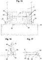
- Figure 11a shows an exemplary embodiment of a carrier device 1 in the installed state on a motor vehicle 2, the carrier device 1 being arranged in the rear area, more precisely under a loading floor of the trunk of the motor vehicle 2, via the fastening device 4 and being in the usage position 18.
- the carrier device 1 of this exemplary embodiment has a fastening device 4 for fastening to the motor vehicle.
- the carrier device can be moved between a use position 18 and a stowed position 17 (via rolling bodies 32) along the pull-out axis 7 via the guide device 6 .
- the carrier device In a stowage position 17 of this exemplary embodiment, the carrier device, more precisely the receiving devices 5 and the guide devices 6 , are completely sunk in the rear area of the motor vehicle 2 .
- the carrier device By pulling out the receiving devices 5 via the guide device 6 along the pull-out axis 7, the carrier device can be transferred into a use position 18, with the receiving devices 5 being able to be folded open about an axis transverse to the pull-out axis 7 when the guide device 6 is pulled out, in order to receive a bicycle 3 .
- a length of the guide device 6 and a number of the receiving devices 5 can be increased, depending on the lengthening of the carrier device 1, with several receiving devices 5 being able to be provided if the motor vehicle 2 has a longer receiving area for the carrier device 1.
- Figure 11b shows the embodiment of Figure 11a in the stowed position 17.
- the carrying device 1 can be arranged at any position between the vehicle underbody and the loading sill of the trunk.
- the guide device 6 for guiding the receiving device 5 has a carrier body 42 which can be moved along the pull-out axis 7 via the guide rails 31 .
- the receiving device 5 is mounted on the carrier body 42 via the hinge 27, with the receiving device 5 being able to be tilted relative to the carrier body 42 of the guiding device 6 about a tilting axis 35 transversely to the extension axis 7 and thus being able to be transferred into a use position 18.
- the usage position 18 of the receiving device 5 is assumed when the receiving device 5 hits the carrier body 42 of the guide device 6 by means of the stops 30 attached to the receiving device 5 due to the tilting transversely to the extraction axis 7 and thus assumes a position locked by 90° relative to the carrier body 42 ( how through 14 can be seen) .
- the recording device 5 of the embodiment of 12 has a height adjustment 28, wherein the V-shaped section 9 for receiving a crank 21 of a bicycle 3 can be adjusted in relation to the carrier body 42 in its distance to be able to be adjusted to different bicycle sizes.
- This height adjustment 28 occurs through an adjustment between the holding plate 36 (which receives the crank 21 of the bicycle 3) in relation to the base plate 46 (which attached to the carrier body 42 via the hinge 27) of the receiving device 5.
- This setting of the holding plate 36 relative to the base plate 46 is done by means of an adjustment using the bolts 37 which connect the holding plate 36 to the base plate 46.
- bores are arranged on the base plate 46, which have a grid in order to enable the holding plate 36 to be adjusted in different heights.
- the retaining plate 36 also has an electrically operated actuator 34 which is designed to close and/or release the receiving area for the crank 21 of the bicycle 3 indicated by dashed lines when the crank 21 of the bicycle 3 is positioned in the receiving area or is removed.
- This electrically operated actuator 34 thus represents the locking device 22 of this exemplary embodiment.
- the actuator 34 is designed as a so-called electric cylinder.
- holding bodies 52 are also optionally provided, which suppress any seesaw movements of the crank 21 and/or of the entire bicycle 3 .
- the variant of the 12 an electrical connection device 13, in which case, for example, electric bicycles (e-bikes) could be loaded when they take their place on the carrier device 1.
- electric bicycles e-bikes
- 15 - 17 show an exemplary embodiment in which locking can be carried out transversely to the pull-out axis 7 when the receiving device 5 is tilted relative to the guide device 6 (carrier body 42).
- the receiving device 5 is folded open via the hinges 27 until the stops 30 provided on the receiving device 5 come into contact with the carrier body 42 .
- the further stops 39 are provided, which are mounted on the receiving device 5 via the dovetail guide 40 .
- the further stops 39 are coupled to one another by the spring element 41 .
- the further stops 39 are located in the recesses 38 (as in 17 shown) their place and thus allow a complete folding of the receiving device 5 to the carrier body 42.
- the other stops 39 are spaced apart from each other by the spring element 41 as soon as they leave the recess 38, so that the stops 39 come into contact with the surface of the carrier body 42 and thus the receiving device 5 secure on both sides against tilting about the tilting axis 35 (as per 16 is shown).
- the further stops 39 can be pressed against one another, as a result of which the spring element 41 is braced and the further stops 39 can enter the recesses 38 again.
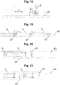
- the Figures 18 - 21 show different embodiment variants of several receiving devices 5 on a carrier body 42 of the guide device 6, wherein the receiving devices 5 are arranged tiltable relative to the guide device 6 by means of a hinge 27 transversely to the pull-out axis 7.
- the distance between the recording devices 5 can be designed differently from one another, as by the 20 and 21 is shown, whereby a crank width of a bicycle 3 is discussed individually can, in order to be able to accommodate wider or thinner bicycles on the carrier device 1 in a space-saving and uncomplicated manner.
- the receiving device 5 always receives one end of the crank, whereas the crank receptacle 43 in the carrier body 42 of the guide device 6 receives the other crank.
- This crank mount 43 is formed by a corresponding slot in the carrier body 42, with one crank of the bicycle finding its place in the crank mount 43 and the other crank of the bicycle 3 on the receiving device 5.
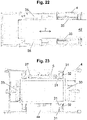
- the 22 and 23 show the carrier device 1 with its fastening device 4 and the guide device 6 in a detailed view.
- the fastening device 4 of this exemplary embodiment forms a box which accommodates the guide device 6 and the receiving device 5 in a stowed position 17 .
- the fastening device 4 can be connected to the vehicle 2 via fastening screws, bolts, welds or the like.
- the guide device 6 of this exemplary embodiment has guide rails 31 (see FIG 23 ), with one guide rail each being arranged on the fastening device 4 and the other guide rail 31 on a carrier body 42 on which the receiving devices 5 are mounted.
- Rolling bodies 32 are arranged between the guide rails 31 so that a relative movement of the two guide rails and thus of the receiving devices 5 with respect to the fastening device 4 is permitted.
- the carrier body 42 can be guided along the pull-out axis 7 with the aid of the guide rails 31 and the rolling bodies 32 in order to move the receiving devices between a use position 18 and a stowed position 17 .
- a locking device is provided, which is implemented by the clamping device 33 .
- This clamping device 33 can be pressed against the carrier body 42 via electrically operated actuators 34, as a result of which a clamping of the carrier body 42 with the fastening device 4 (similar to a shoe brake) is implemented via a frictional force.
- This clamping device 33 creates the possibility of locking the receiving devices 5 in various positions along the pull-out axis 7 in relation to the fastening body 4 in a freely selectable manner.
- a so-called electric cylinder can be used as the actuator 34, for example which presses the clamping jaws onto the receiving device via a lever.
- the electric cylinder can be locked in a locked position, so that energy does not have to be constantly used for clamping.
- a shaft 44 can be seen, via which the electrically operated actuators and/or other electrical consumers of the carrier device 1 can obtain their power supply or their electrical connection.
- the electrically actuated actuators 34 or vehicle lights 15 arranged on the carrier device 1 can be connected via the shaft 44 and/or cable harness 45 of the carrier device 1, such as by 24 is shown.
- this wiring harness 45 can be coupled to an electrical system of the motor vehicle, so that the actuators can supply an e-bike connection option or the motor vehicle lighting 15 of the carrier device 1 through the electrical motor vehicle system and the wiring harness 45 .
- FIG. 24 shows a plan view of an embodiment of a carrier device 1, the carrier device 1 being in a stowed position 17.
- FIG. 24 shows a plan view of an embodiment of a carrier device 1, the carrier device 1 being in a stowed position 17.
- the carrier body 42 of the guide device 6 and the receiving devices 5 are pushed into the box-shaped fastening device 4 .
- the motor vehicle lights 15 are folded in at the side and also drawn into the fastening device 4 .
- the receiving devices 5 are now pulled out of the fastening device 4 along the extraction axis 7 via the guide device 6 and are transferred into a use position 18, the receiving devices 5 can be tilted transversely to the extraction axis 7, for example by 25 is shown.
- the motor vehicle lights 15 can be swiveled out via the pivot points 47 in order to be converted into a use position.
- an inner tube 48 on which the motor vehicle lights 15 are arranged is moved via a bolt serving as a pivot point 47 in relation to an outer tube 49 arranged on the support body 42 of the guide device 6, with the pivot point 47 serving bolts in a guide link 50 of the outer tube 49 is moved, as by the 26 and 27 can be seen.
- fastening screws 51 are provided which can cause a clamping between the outer tube 49 and the inner tube 48 by tightening and loosening.
Landscapes
- Engineering & Computer Science (AREA)
- Mechanical Engineering (AREA)
- Fittings On The Vehicle Exterior For Carrying Loads, And Devices For Holding Or Mounting Articles (AREA)
Applications Claiming Priority (1)
| Application Number | Priority Date | Filing Date | Title |
|---|---|---|---|
| AT501182021 | 2021-02-22 |
Publications (3)
| Publication Number | Publication Date |
|---|---|
| EP4046873A1 true EP4046873A1 (fr) | 2022-08-24 |
| EP4046873C0 EP4046873C0 (fr) | 2024-10-23 |
| EP4046873B1 EP4046873B1 (fr) | 2024-10-23 |
Family
ID=80446043
Family Applications (1)
| Application Number | Title | Priority Date | Filing Date |
|---|---|---|---|
| EP22157825.5A Active EP4046873B1 (fr) | 2021-02-22 | 2022-02-21 | Dispositif de support pour un véhicule automobile |
Country Status (4)
| Country | Link |
|---|---|
| EP (1) | EP4046873B1 (fr) |
| AT (1) | AT524815B1 (fr) |
| ES (1) | ES3009499T3 (fr) |
| PL (1) | PL4046873T3 (fr) |
Cited By (2)
| Publication number | Priority date | Publication date | Assignee | Title |
|---|---|---|---|---|
| US20230353180A1 (en) * | 2022-04-29 | 2023-11-02 | Robert Bosch Gmbh | Communication unit having a fastening device for fastening to a component of an in particular single-track vehicle |
| US12425060B2 (en) * | 2022-04-29 | 2025-09-23 | Robert Bosch Gmbh | Communications unit having a fastening device for fastening to a component of an in particular single-track vehicle |
Citations (13)
| Publication number | Priority date | Publication date | Assignee | Title |
|---|---|---|---|---|
| DE19521886A1 (de) | 1995-06-16 | 1996-06-20 | Daimler Benz Ag | Fahrradträger für Kraftwagen |
| DE10352644A1 (de) | 2003-11-11 | 2005-06-23 | Adam Opel Ag | Heckträger für ein Kraftfahrzeug |
| DE202005012475U1 (de) | 2005-08-09 | 2005-10-20 | Friese, Otto | Integrierter Fahrradträger |
| DE102004057649A1 (de) | 2004-11-29 | 2006-06-01 | Volkswagen Ag | Heckträgeranordnung für ein Kraftfahrzeug |
| EP1876059A1 (fr) | 2006-07-08 | 2008-01-09 | Magna Car Top Systems GmbH | Dispositif de retenue pour un vélo |
| US20080006667A1 (en) * | 2006-07-08 | 2008-01-10 | Magna Car Top Systems Gmbh | Carrier device for a bicycle |
| US20100045012A1 (en) * | 2007-04-12 | 2010-02-25 | Gm Global Technology Operations, Inc. | Load carrier for a motor vehicle |
| US20110108592A1 (en) * | 2009-11-06 | 2011-05-12 | Hyundai Motor Company | Bicycle Carrier for Vehicle |
| DE202011109330U1 (de) | 2011-12-21 | 2012-01-26 | Gm Global Technology Operations Llc, ( N.D. Ges. D. Staates Delaware) | Ausklappbarer Bügelträger für einen Fahrradträger |
| US20130182454A1 (en) * | 2011-12-21 | 2013-07-18 | GM Global Technology Operations LLC | Extendible and pivotable bicycle rack |
| DE202015105297U1 (de) | 2014-10-16 | 2016-02-02 | Ford Global Technologies, Llc | Fahrradträgerhaltung für ein Fahrzeug |
| US20160288729A1 (en) * | 2015-04-03 | 2016-10-06 | Hyundai Motor Company | Bicycle carrier system for vehicle |
| EP3386070A1 (fr) * | 2017-04-07 | 2018-10-10 | Continental Automotive GmbH | Système de charge d'un accumulateur de bicyclette électrique, support pour bicyclette et procédé pour charger un accumulateur |
Family Cites Families (7)
| Publication number | Priority date | Publication date | Assignee | Title |
|---|---|---|---|---|
| US5123802A (en) * | 1990-08-23 | 1992-06-23 | Bell Francis C | Motorcycle wheel lift adapter kit |
| US5947357A (en) * | 1998-04-20 | 1999-09-07 | Surkin; Uri | Bicycle rack |
| US7635247B2 (en) * | 2005-02-02 | 2009-12-22 | Collins Douglas A | Telescoping vehicle step |
| KR101171790B1 (ko) * | 2010-07-30 | 2012-08-13 | 현대자동차주식회사 | 인출식 자전거 캐리어 |
| EP2428403B1 (fr) * | 2010-09-13 | 2014-01-15 | WESTFALIA - Automotive GmbH | Couplage pour un système de support de charge doté d'une unité de contact |
| DE102012002261A1 (de) * | 2012-02-07 | 2013-08-08 | Magna Car Top Systems Gmbh | Ausziehbarer Lasten-Heckträger für ein Fahrzeug |
| US9180821B1 (en) * | 2014-05-14 | 2015-11-10 | Robert W Freet | Bicycle carrier |
-
2022
- 2022-02-21 ES ES22157825T patent/ES3009499T3/es active Active
- 2022-02-21 EP EP22157825.5A patent/EP4046873B1/fr active Active
- 2022-02-21 PL PL22157825.5T patent/PL4046873T3/pl unknown
- 2022-02-22 AT ATA51/2022A patent/AT524815B1/de active
Patent Citations (14)
| Publication number | Priority date | Publication date | Assignee | Title |
|---|---|---|---|---|
| DE19521886A1 (de) | 1995-06-16 | 1996-06-20 | Daimler Benz Ag | Fahrradträger für Kraftwagen |
| DE10352644A1 (de) | 2003-11-11 | 2005-06-23 | Adam Opel Ag | Heckträger für ein Kraftfahrzeug |
| DE102004057649A1 (de) | 2004-11-29 | 2006-06-01 | Volkswagen Ag | Heckträgeranordnung für ein Kraftfahrzeug |
| DE202005012475U1 (de) | 2005-08-09 | 2005-10-20 | Friese, Otto | Integrierter Fahrradträger |
| EP1876059A1 (fr) | 2006-07-08 | 2008-01-09 | Magna Car Top Systems GmbH | Dispositif de retenue pour un vélo |
| US20080006667A1 (en) * | 2006-07-08 | 2008-01-10 | Magna Car Top Systems Gmbh | Carrier device for a bicycle |
| US20100045012A1 (en) * | 2007-04-12 | 2010-02-25 | Gm Global Technology Operations, Inc. | Load carrier for a motor vehicle |
| US20110108592A1 (en) * | 2009-11-06 | 2011-05-12 | Hyundai Motor Company | Bicycle Carrier for Vehicle |
| DE102010017182B4 (de) | 2009-11-06 | 2020-06-18 | Hyundai Motor Co. | Fahrradträger eines Fahrzeuges |
| DE202011109330U1 (de) | 2011-12-21 | 2012-01-26 | Gm Global Technology Operations Llc, ( N.D. Ges. D. Staates Delaware) | Ausklappbarer Bügelträger für einen Fahrradträger |
| US20130182454A1 (en) * | 2011-12-21 | 2013-07-18 | GM Global Technology Operations LLC | Extendible and pivotable bicycle rack |
| DE202015105297U1 (de) | 2014-10-16 | 2016-02-02 | Ford Global Technologies, Llc | Fahrradträgerhaltung für ein Fahrzeug |
| US20160288729A1 (en) * | 2015-04-03 | 2016-10-06 | Hyundai Motor Company | Bicycle carrier system for vehicle |
| EP3386070A1 (fr) * | 2017-04-07 | 2018-10-10 | Continental Automotive GmbH | Système de charge d'un accumulateur de bicyclette électrique, support pour bicyclette et procédé pour charger un accumulateur |
Cited By (2)
| Publication number | Priority date | Publication date | Assignee | Title |
|---|---|---|---|---|
| US20230353180A1 (en) * | 2022-04-29 | 2023-11-02 | Robert Bosch Gmbh | Communication unit having a fastening device for fastening to a component of an in particular single-track vehicle |
| US12425060B2 (en) * | 2022-04-29 | 2025-09-23 | Robert Bosch Gmbh | Communications unit having a fastening device for fastening to a component of an in particular single-track vehicle |
Also Published As
| Publication number | Publication date |
|---|---|
| AT524815A2 (de) | 2022-09-15 |
| AT524815B1 (de) | 2023-03-15 |
| AT524815A3 (de) | 2022-10-15 |
| ES3009499T3 (en) | 2025-03-27 |
| PL4046873T3 (pl) | 2025-03-24 |
| EP4046873C0 (fr) | 2024-10-23 |
| EP4046873B1 (fr) | 2024-10-23 |
Similar Documents
| Publication | Publication Date | Title |
|---|---|---|
| DE102010006514A1 (de) | Fahrzeug mit einer in einem Batterieträger angeordneten Batterie | |
| EP4046873B1 (fr) | Dispositif de support pour un véhicule automobile | |
| DE4330045A1 (de) | Trägersystem für ein zweirädriges Fahrzeug | |
| EP1972501B1 (fr) | Support de charge pour un véhicule automobile | |
| DE4320993C2 (de) | Kompakter Personenwagen | |
| EP2657051B1 (fr) | Agencement de couplage pour un support de toit | |
| DE60115484T2 (de) | System zum zweiseitigem laden von lastkraftwagen | |
| EP2428406B1 (fr) | Support de charge coulissant et basculant | |
| DE102020128870A1 (de) | Anbauvorrichtung für ein Kraftfahrzeug mit zwei Abschleppösenaufnahmen | |
| WO2010100164A1 (fr) | Dispositif de soutien d'une prise de charge pour un véhicule à entraînement électrique | |
| DE102008019396B4 (de) | Laderaum für ein Kraftfahrzeug | |
| DE68915877T2 (de) | Strasseneinheit mit absetzbarer Trägerkarosserie. | |
| DE102004064293A1 (de) | Klappbare Unterfahrschutzeinrichtung | |
| DE4128701A1 (de) | Schutzwand zur abtrennung des fahrgastraumes eines kraftfahrzeuges von einem dahinter gelegenen laderaum | |
| DE102015001804A1 (de) | Lastenträger zur Anordnung am Heck eines Kraftfahrzeugs | |
| DE202023100599U1 (de) | Innenlader mit variablem Unterfahrschutz | |
| EP4227161A1 (fr) | Porte-charge arrière | |
| DE102019129401B4 (de) | Fahrradträger-Befestigungsvorrichtung, Kraftfahrzeug und Kraftfahrzeuganhänger | |
| EP2650176B1 (fr) | Structure de charge avec une composant supplémentaire ayant une gamme de plusieurs degrés de mouvement | |
| WO2022238266A1 (fr) | Dispositif de chargement et ensemble de transport et de chargement | |
| DE102020214612B4 (de) | Heckträger für ein Kraftfahrzeug | |
| EP4414251B1 (fr) | Chargeur interne avec protection de sous-traction variable | |
| DE102005037176A1 (de) | Vorrichtung zum Unterteilen eines Laderaums eines Fahrzeugs | |
| DE19521504C2 (de) | Großraumschubladeneinrichtung zum Einbau in Servicefahrzeuge | |
| EP2368766B1 (fr) | Caisse de transport |
Legal Events
| Date | Code | Title | Description |
|---|---|---|---|
| PUAI | Public reference made under article 153(3) epc to a published international application that has entered the european phase |
Free format text: ORIGINAL CODE: 0009012 |
|
| STAA | Information on the status of an ep patent application or granted ep patent |
Free format text: STATUS: THE APPLICATION HAS BEEN PUBLISHED |
|
| AK | Designated contracting states |
Kind code of ref document: A1 Designated state(s): AL AT BE BG CH CY CZ DE DK EE ES FI FR GB GR HR HU IE IS IT LI LT LU LV MC MK MT NL NO PL PT RO RS SE SI SK SM TR |
|
| STAA | Information on the status of an ep patent application or granted ep patent |
Free format text: STATUS: REQUEST FOR EXAMINATION WAS MADE |
|
| 17P | Request for examination filed |
Effective date: 20230117 |
|
| RBV | Designated contracting states (corrected) |
Designated state(s): AL AT BE BG CH CY CZ DE DK EE ES FI FR GB GR HR HU IE IS IT LI LT LU LV MC MK MT NL NO PL PT RO RS SE SI SK SM TR |
|
| STAA | Information on the status of an ep patent application or granted ep patent |
Free format text: STATUS: EXAMINATION IS IN PROGRESS |
|
| 17Q | First examination report despatched |
Effective date: 20231116 |
|
| GRAP | Despatch of communication of intention to grant a patent |
Free format text: ORIGINAL CODE: EPIDOSNIGR1 |
|
| STAA | Information on the status of an ep patent application or granted ep patent |
Free format text: STATUS: GRANT OF PATENT IS INTENDED |
|
| INTG | Intention to grant announced |
Effective date: 20240607 |
|
| GRAS | Grant fee paid |
Free format text: ORIGINAL CODE: EPIDOSNIGR3 |
|
| GRAA | (expected) grant |
Free format text: ORIGINAL CODE: 0009210 |
|
| STAA | Information on the status of an ep patent application or granted ep patent |
Free format text: STATUS: THE PATENT HAS BEEN GRANTED |
|
| AK | Designated contracting states |
Kind code of ref document: B1 Designated state(s): AL AT BE BG CH CY CZ DE DK EE ES FI FR GB GR HR HU IE IS IT LI LT LU LV MC MK MT NL NO PL PT RO RS SE SI SK SM TR |
|
| REG | Reference to a national code |
Ref country code: GB Ref legal event code: FG4D Free format text: NOT ENGLISH |
|
| REG | Reference to a national code |
Ref country code: CH Ref legal event code: EP |
|
| REG | Reference to a national code |
Ref country code: DE Ref legal event code: R096 Ref document number: 502022001935 Country of ref document: DE |
|
| REG | Reference to a national code |
Ref country code: IE Ref legal event code: FG4D Free format text: LANGUAGE OF EP DOCUMENT: GERMAN |
|
| U01 | Request for unitary effect filed |
Effective date: 20241118 |
|
| U07 | Unitary effect registered |
Designated state(s): AT BE BG DE DK EE FI FR IT LT LU LV MT NL PT RO SE SI Effective date: 20241122 |
|
| U20 | Renewal fee for the european patent with unitary effect paid |
Year of fee payment: 4 Effective date: 20241223 |
|
| REG | Reference to a national code |
Ref country code: ES Ref legal event code: FG2A Ref document number: 3009499 Country of ref document: ES Kind code of ref document: T3 Effective date: 20250327 |
|
| PG25 | Lapsed in a contracting state [announced via postgrant information from national office to epo] |
Ref country code: HR Free format text: LAPSE BECAUSE OF FAILURE TO SUBMIT A TRANSLATION OF THE DESCRIPTION OR TO PAY THE FEE WITHIN THE PRESCRIBED TIME-LIMIT Effective date: 20241023 Ref country code: IS Free format text: LAPSE BECAUSE OF FAILURE TO SUBMIT A TRANSLATION OF THE DESCRIPTION OR TO PAY THE FEE WITHIN THE PRESCRIBED TIME-LIMIT Effective date: 20250223 |
|
| PG25 | Lapsed in a contracting state [announced via postgrant information from national office to epo] |
Ref country code: NO Free format text: LAPSE BECAUSE OF FAILURE TO SUBMIT A TRANSLATION OF THE DESCRIPTION OR TO PAY THE FEE WITHIN THE PRESCRIBED TIME-LIMIT Effective date: 20250123 |
|
| PG25 | Lapsed in a contracting state [announced via postgrant information from national office to epo] |
Ref country code: GR Free format text: LAPSE BECAUSE OF FAILURE TO SUBMIT A TRANSLATION OF THE DESCRIPTION OR TO PAY THE FEE WITHIN THE PRESCRIBED TIME-LIMIT Effective date: 20250124 |
|
| PG25 | Lapsed in a contracting state [announced via postgrant information from national office to epo] |
Ref country code: RS Free format text: LAPSE BECAUSE OF FAILURE TO SUBMIT A TRANSLATION OF THE DESCRIPTION OR TO PAY THE FEE WITHIN THE PRESCRIBED TIME-LIMIT Effective date: 20250123 |
|
| PG25 | Lapsed in a contracting state [announced via postgrant information from national office to epo] |
Ref country code: SM Free format text: LAPSE BECAUSE OF FAILURE TO SUBMIT A TRANSLATION OF THE DESCRIPTION OR TO PAY THE FEE WITHIN THE PRESCRIBED TIME-LIMIT Effective date: 20241023 |
|
| PGFP | Annual fee paid to national office [announced via postgrant information from national office to epo] |
Ref country code: ES Payment date: 20250331 Year of fee payment: 4 |
|
| PG25 | Lapsed in a contracting state [announced via postgrant information from national office to epo] |
Ref country code: SK Free format text: LAPSE BECAUSE OF FAILURE TO SUBMIT A TRANSLATION OF THE DESCRIPTION OR TO PAY THE FEE WITHIN THE PRESCRIBED TIME-LIMIT Effective date: 20241023 |
|
| PG25 | Lapsed in a contracting state [announced via postgrant information from national office to epo] |
Ref country code: CZ Free format text: LAPSE BECAUSE OF FAILURE TO SUBMIT A TRANSLATION OF THE DESCRIPTION OR TO PAY THE FEE WITHIN THE PRESCRIBED TIME-LIMIT Effective date: 20241023 |
|
| PLBE | No opposition filed within time limit |
Free format text: ORIGINAL CODE: 0009261 |
|
| STAA | Information on the status of an ep patent application or granted ep patent |
Free format text: STATUS: NO OPPOSITION FILED WITHIN TIME LIMIT |
|
| PG25 | Lapsed in a contracting state [announced via postgrant information from national office to epo] |
Ref country code: MC Free format text: LAPSE BECAUSE OF FAILURE TO SUBMIT A TRANSLATION OF THE DESCRIPTION OR TO PAY THE FEE WITHIN THE PRESCRIBED TIME-LIMIT Effective date: 20241023 |
|
| 26N | No opposition filed |
Effective date: 20250724 |
|
| U20 | Renewal fee for the european patent with unitary effect paid |
Year of fee payment: 5 Effective date: 20251211 |
|
| PG25 | Lapsed in a contracting state [announced via postgrant information from national office to epo] |
Ref country code: IE Free format text: LAPSE BECAUSE OF NON-PAYMENT OF DUE FEES Effective date: 20250221 |
|
| PGFP | Annual fee paid to national office [announced via postgrant information from national office to epo] |
Ref country code: PL Payment date: 20251120 Year of fee payment: 5 |
|
| REG | Reference to a national code |
Ref country code: CH Ref legal event code: U11 Free format text: ST27 STATUS EVENT CODE: U-0-0-U10-U11 (AS PROVIDED BY THE NATIONAL OFFICE) Effective date: 20260301 |
|
| PGFP | Annual fee paid to national office [announced via postgrant information from national office to epo] |
Ref country code: GB Payment date: 20260220 Year of fee payment: 5 |
|
| PGFP | Annual fee paid to national office [announced via postgrant information from national office to epo] |
Ref country code: TR Payment date: 20260216 Year of fee payment: 5 |
|
| PGFP | Annual fee paid to national office [announced via postgrant information from national office to epo] |
Ref country code: CH Payment date: 20260301 Year of fee payment: 5 |