EP4046873A1 - Holder device for a motor vehicle - Google Patents
Holder device for a motor vehicle Download PDFInfo
- Publication number
- EP4046873A1 EP4046873A1 EP22157825.5A EP22157825A EP4046873A1 EP 4046873 A1 EP4046873 A1 EP 4046873A1 EP 22157825 A EP22157825 A EP 22157825A EP 4046873 A1 EP4046873 A1 EP 4046873A1
- Authority
- EP
- European Patent Office
- Prior art keywords
- carrier
- motor vehicle
- bicycle
- carrier device
- receiving
- Prior art date
- Legal status (The legal status is an assumption and is not a legal conclusion. Google has not performed a legal analysis and makes no representation as to the accuracy of the status listed.)
- Granted
Links
Images


Classifications
-
- B—PERFORMING OPERATIONS; TRANSPORTING
- B60—VEHICLES IN GENERAL
- B60R—VEHICLES, VEHICLE FITTINGS, OR VEHICLE PARTS, NOT OTHERWISE PROVIDED FOR
- B60R9/00—Supplementary fittings on vehicle exterior for carrying loads, e.g. luggage, sports gear or the like
- B60R9/08—Supplementary fittings on vehicle exterior for carrying loads, e.g. luggage, sports gear or the like specially adapted for sports gear
- B60R9/10—Supplementary fittings on vehicle exterior for carrying loads, e.g. luggage, sports gear or the like specially adapted for sports gear for cycles
-
- B—PERFORMING OPERATIONS; TRANSPORTING
- B60—VEHICLES IN GENERAL
- B60R—VEHICLES, VEHICLE FITTINGS, OR VEHICLE PARTS, NOT OTHERWISE PROVIDED FOR
- B60R9/00—Supplementary fittings on vehicle exterior for carrying loads, e.g. luggage, sports gear or the like
- B60R9/06—Supplementary fittings on vehicle exterior for carrying loads, e.g. luggage, sports gear or the like at vehicle front or rear
Definitions
- the present invention relates to a carrier device for a motor vehicle for fastening at least one bicycle with the features of the preamble of claim 1 and a motor vehicle with such a carrier device.
- Motor vehicles can be, for example, passenger cars, trucks or other vehicles for transporting people.
- passenger cars trucks or other vehicles for transporting people.
- the state of the art will be briefly outlined using passenger cars. The same applies in general to motor vehicles.
- Corresponding carrier devices are connected to the at least one fastening device, mostly in a rear area of the passenger vehicle on the bumper or underneath the vehicle.
- the connection can be made via a welded or screwed connection can be made, for example, on the chassis of the vehicle.
- the receiving device which is designed to receive the at least one bicycle, can then be pulled out of this lower or rear area along a direction of travel of the vehicle via the guide device, so that the carrier device is hidden in a stowed position in the rear area or below the vehicle and at Use can be converted into a use position on the guide device.
- Such well-known from the prior art support devices go for example from DE 102010017182 B1 , the DE 202015105297 U1 , the EP 1876059 A1 , the DE 202011109330 U1 , the DE 102004057649 A1 , the DE 10352644 A1 , the DE 19521886 A1 or the DE 202005012475 U1 out.
- a disadvantage of such carrier devices from the prior art is that the fastening device takes up a relatively wide and large area on the passenger vehicle and also requires a corresponding holder there, so that a fairly large area for attaching the carrier device has to be adapted or is lost on the vehicle side. which is required for vehicle components such as chassis, drive or exhaust system.
- the carrier device is in the rear area of the vehicle when it is in use fastening devices protruding at right angles (which are required, for example, to attach a bicycle to the frame via retaining claws) are provided, which in a stowed position impairs the free accessibility of the vehicle, so that in many cases, for example, the trunk can no longer be opened or is only accessible with difficulty.
- This usually makes it necessary to disassemble parts of the carrying device before the carrying device is transferred to a stowed position.
- the object of the present invention is to provide a carrier device and a motor vehicle with such a carrier device which at least partially improves the disadvantages of the prior art described above and/or increases user-friendliness and/or requires less space on the motor vehicle.
- a device according to the invention can also be used in already known design variants of the prior art, as also described, for example, by the introduction to the description, and can be installed subsequently.
- the at least one bicycle can be accommodated in the foldable accommodation device, for example with the crank locked between the frame and the crank of the bicycle.
- each holding device can be moved separately between the stowed position and at least one use position by tilting about the pull-out axis and/or by folding about an axis transverse to the pull-out axis.
- the tilting according to the invention of the at least one receiving element can be over an angle of more than 30°, preferably more than 60° and particularly preferably more than 80°. pass. In particularly preferred embodiments, the tilting can extend essentially over a 90° angle.
- an L-shaped configuration of the pull-out device can be undertaken, with the "L” being folded over during a transfer between the use position and the stowed position.
- the at least one receiving device is additionally connected to the at least one guide device such that it can be folded about a, preferably adjustable, transverse axis to the pull-out axis.
- the at least one receiving device can protrude from the guide device at a right angle in the use position and can rest against the guide device in the stowed position. As a result, even more space can be saved in the stowage position on or in the vehicle.
- the at least one receiving device can be converted into a use position by folding about an axis transverse to the pull-out axis, the at least one receiving device being secured by at least one locking device, preferably at least a stop which can be releasably locked against tilting in the use position.
- a U-shaped or V-shaped section can, for example, provide for the receiving device to have a U-shaped or V-shaped cutout, with a pedal or crank of the at least one bicycle being able to engage at the apex of the U-shaped or V-shaped cutout or can be attached to be transported with the carrier device can.
- this U- or V-shaped section points upwards, a particularly simple assembly of the at least one bicycle can thereby be made possible, the at least one bicycle being able to be lifted into the U- or V-shaped section only from above and thereby immediately is held without a assembling person having to continue holding the weight of the bicycle. Due to the arrangement of the carrier device according to the invention in or under a bumper, the at least one bicycle does not have to be lifted very high at the same time.
- the height of the at least one receiving device can be adjusted relative to the at least one fastening device in a mounted state on a motor vehicle.
- At least one detachable connecting device preferably at least one removable and/or foldable (and thus e.g. stowable) connecting tube, is provided for mounting the at least one clamping element on the at least one receiving device.
- At least one clamping element is foldable on the at least one receiving device, wherein the at least one clamping element can be folded onto the at least one bicycle in the use position and onto the at least one receiving device and/or others in the stowed position the at least one fastening device can be folded down.
- the connecting device includes a recess in which, for example, a tube or rod-like element can be fastened, on which the clamping element is arranged (for example, a holding claw).
- the at least one guiding device can contain tubes guided into one another.
- the outer or inner tube has a guide pin, which is guided, for example, in a guide link on the other tube, with the (e.g. L-shaped) guide link already guiding the pin between a stowed position and a use position, with one Rotational movement is included.
- the at least one guide rail or the at least one rolling body can be connected to the fastening device and/or receiving device in a motion-locked manner in the direction of the extension axis, with the receiving device being movable relative to the fastening device between the stowed position and the use position via a relative movement between the guide rail and rolling body.
- At least two guide rails and at least one rolling body arranged between the at least two guide rails, particularly preferably at least one rolling body are provided. Provision can be made for one of the at least two guide rails to be connected to the fastening device and the other of the at least two guide rails to be connected to the receiving device in a non-moving manner relative to the pull-out axis, with movement of the at least two guide rails relative to one another being permitted via the at least one rolling body (similar to a drawer slide) .
- At least one electrical connecting line is provided, which electrical connecting line is designed to To connect e-bike to a power source of the motor vehicle.
- the at least one receiving device can be locked in relation to the at least one fastening device by means of a locking device, preferably at least one clamping device, in the stowage position and/or in the at least one use position, preferably any use position.
- a locking device preferably at least one clamping device
- the at least one clamping device can, for example, have at least one clamping jaw, preferably actuated by an actuator, wherein by applying force to the at least one clamping jaw relative to a corresponding counterpart, the receiving device can be locked relative to the fastening device via a clamping force (and a resulting frictional force - similar to a shoe brake).
- the actuator for actuating the at least one clamping device can, for example, be designed to be electrically or hydraulically actuated.
- Such a locking device can also be provided, for example, by a bolt which allows movement of the guide device in the use or the Stowage position prevented.
- the locking is provided by the end positions of the guide device.
- the guide device includes a guide link--the end positions already bring about a locking between the fastening device and the receiving device.
- At least one drive is provided, wherein the at least one drive is designed to move the at least one receiving device between the stowed position and the at least one use position.
- the carrier device in particular the drive unit
- the at least one drive could be controlled via the operation of the motor vehicle in order to move the at least one receiving device between the stowed position and the at least one use position move.
- a license plate holder By arranging a license plate holder at the end of the at least one receiving device facing away from the fastening device, for example, a license plate can be moved with the carrier device and it is no longer necessary to remove it separately from the vehicle and to arrange it on a bicycle carrier. The same applies, of course, to the vehicle lighting or a warning device (such as a cat's eyes).
- Protection is also sought for a bicycle comprising at least one crank and/or at least one handlebar, the bicycle having at least one locking device, which at least one locking device is designed to prevent the crank and/or a handlebar of the at least one bicycle from twisting, preferably motionally rigid, to lock releasably.
- Protection is also sought for an arrangement of a carrier device according to the invention and at least one bicycle according to the invention.
- a motor vehicle with a carrier device according to the invention, the carrier device being connected to the motor vehicle, preferably to a chassis of the motor vehicle, via the at least one fastening device. Provision can preferably be made for the carrier device to be arranged in a rear area of the motor vehicle in the direction of travel, with the at least one receiving device being retracted into or under a bumper of the motor vehicle when the carrier device is in the stowed position and by the bumper of the motor vehicle in the at least one use position is spaced in the direction of travel.
- the carrier device can be integrated into the vehicle.
- FIG. 1 shows a first exemplary embodiment of a carrier device 1 according to the invention in a stowed position 17, the carrier device 1 being fastened to a motor vehicle 2 via its fastening device 4.
- the carrier device 1 is arranged in a rear area of the motor vehicle 2 in the direction of travel 16 .
- the receiving device 5 is retracted into a bumper of the motor vehicle 2 in a stowed position 17 of the carrier device 1 .
- the receiving device 5 can be moved between a stowed position 17 and a use position 18 via the guide device 6 of the carrier device 1, with the guide device 6 being designed in such a way that the receiving device 5 relative to the motor vehicle 2 along an extension axis 7 (which in this exemplary embodiment corresponds to the direction of travel 16 of the motor vehicle 2) is pulled out into a use position 18, wherein the receiving device 5 can be moved after being pulled out between the stowed position 17 and the use position 18 by tilting about the pull-out axis 7 (as indicated by the movement illustrated as an arrow in 1 can be seen) .
- the fastening device 4 of the carrier device 1 holds the carrier device 1 on the motor vehicle 2 and can be connected to the chassis of the motor vehicle 2 by screwing or welding.
- the receiving device 5 is designed to receive at least one bicycle 3, as will be explained in more detail in the following figures.
- the guide device 6 of this exemplary embodiment is formed by two tubes that are guided into one another, with the receiving device 5 being guided in relation to the fastening device 4 .
- the receiving device 5 By tilting the receiving device 5 about the pull-out axis 7 , the receiving device can be positioned in a use position 18 for receiving a bicycle 3 .
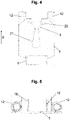
- FIG 2 shows a plan view of the embodiment of FIG 1 , wherein the carrier device 1 is located in 2 is in a use position 18 .
- the carrier device 1 also has two foldable signaling elements 20 which, in the use position 18 of the fastening device 4 , are provided on an end of the receiving device 5 which is remote from the motor vehicle 2 .
- These foldable signal elements 20 can be opened by 90° relative to the pull-out axis 7 (as indicated by the arrows) and carry the motor vehicle lighting 15 (for example indicators, rear lights or brake lights).
- a license plate holder 14 is provided on the end of the receiving device 5 facing away from the fastening device 4 and can be pulled out and opened together with the receiving device 5 via the guide device 6 relative to the fastening device 4 .
- the signal elements 20 can be folded onto the receiving device 5 when being transferred between the use position and the stowed position (as shown by the arrows) and together with this can be pushed into the rear area of the motor vehicle (or under the motor vehicle) so that they are in the stowed position 17 are hidden from a viewer.
- FIG. 3 shows a further exemplary embodiment of a carrier device 1 according to the invention, which is designed to accommodate a plurality of bicycles 3, with these bicycles 3 each being able to be accommodated on one of four receiving devices 5, with a total of four bicycles being able to be transported in this exemplary embodiment.
- the four receiving devices 5 are part of a common supporting structure which connects the receiving devices 5 to the guiding device 6 .
- each holding device 5 has connecting devices 12 which can hold clamping elements 10 for fastening the bicycles 3 (more details on this in the following figures).
- the carrier device 1 of this embodiment of the 3 has an electrical connecting line 13 .
- This electrical connecting line 13 is used to connect the motor vehicle lighting 15 to the lighting system of the motor vehicle 2 .
- this electrical connecting line 13 is used to provide a power source on the carrier device 1 for e-bikes, which is connected to the power source of the motor vehicle 2, so that e-bikes are charged via the carrier device 1 (e.g. during transport of the e-bike). can become.
- the receiving devices 5 of this exemplary embodiment can be locked in a stowage position 17 and a use position 18 by a locking device, whereby it can also be provided, for example, that several use positions 18 are provided, so that only one recording for a bicycle 3 protrudes from the rear of the motor vehicle. which is currently required for use.
- the locking can be effected, for example, by a bolt, which inhibits a movement of the guide device 6 by passing through the tubes guided into one another through correspondingly arranged bores and thus inhibiting a movement between the receiving device 5 and the fastening device 4 .
- a drive is provided, which drive moves the receiving device between a stowed position 17 and a use position 18 .
- This drive can also be used as a locking device if it is blocked.
- the guide device it is also conceivable for the guide device to have a guide link 25, in which a guide pin 26 is guided, with locking positions being provided at the end positions (or also in intermediate positions) of the guide link 25, so that the receiving device 5 is in a use position 18 and a stowed position 17 can be locked.
- this carrier device 1 for example license plate holder 14, motor vehicle lighting 15 or signal elements 20
- This carrier device 1 for example license plate holder 14, motor vehicle lighting 15 or signal elements 20
- 4 shows in more detail an example of a receiving device 5 for receiving a bicycle 3, wherein 4 represents a view along the extraction axis 7 of the carrier device 1 and figure 5 a top view of the 4 .
- This receiving device 5 is welded onto the guide device 6 of the carrier device 1 and extends at right angles to it.
- the receiving device 5 is designed to be foldable relative to the guide device 6 (e.g. by means of hinges), so that the receiving device 5 can also be folded over about an axis transverse to the extension axis 7 between the use position 18 and the stowed position 17, with the Recording device 5 in the use position 18 protrudes from the guide device 6 at a right angle and rests against the guide device 6 in the stowed position 17 .
- the receiving device 5 is designed to be foldable relative to the guide device 6 (e.g. by means of hinges), so that the receiving device 5 can also be folded over about an axis transverse to the extension axis 7 between the use position 18 and the stowed position 17, with the Recording device 5 in the use position 18 protrudes from the guide device 6 at a right angle and rests against the guide device 6 in the stowed position 17 .
- the receiving device 5 has a V-shaped section 9 .
- the V-shaped section 9 is designed to receive a pedal and/or a crank 21 of a bicycle 3 (as indicated in Fig 4 broken-line crank 21 of a bicycle 3 is indicated).
- the bicycle 3 has a locking mechanism which allows the position of the crank 21 to be locked relative to the bicycle 3, so that the position of the bicycle 3 relative to the carrier device 1 is secured by fastening the crank 21 to the receiving device 5 of the carrier device 1 can.
- clamping elements 10 for fastening the bicycle 3.
- These clamping elements 10 can be attached to the connecting devices 12 of the receiving device 5, as shown below 6 is evident.
- This crank 21 of the bicycle 3 can be blocked, for example, via a locking device 22 shown in dashed lines, and secure the bicycle 3 against theft.
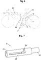
- FIG. 6 shows a carrier device 1 in use, with the receiving device 5 receiving a bicycle 3 .
- the bicycle 3 is inserted with the crank 21 into the V-shaped section 9 of the longitudinal extent 8, with the other crank 21 of the bicycle 3 finding its place in a recess in the guide device 6/receiving device 5 (see also 3 ).
- clamping elements 10 which are attached to the receiving device 5 by means of the connecting devices 12, the bicycle 3 can be additionally clamped, so that the bicycle 3 is secured in its position relative to the carrier device 1.
- the clamping elements are designed as retaining claws.
- the connecting devices 12 of the receiving device 5 have connecting tubes or connecting rods, which can be inserted into tube-like recesses and can be held in these recesses by clamping and/or providing a guide or locking link.
- FIG. 7 shows an embodiment of a guide device 6 of a carrier device 1 according to the invention, wherein the guide device 6 has two tubes 23, 24 guided inside one another.
- the inner tube 23 has a guide pin 26 which is positively connected to the inner tube 23 .
- the inner tube 23 can also be designed, for example, as a shaft or journal (solid component).
- the guide pin 26 of the inner tube 23 is guided in the slotted guide 25 of the outer tube 24 .
- the guide device 6 shown is in a use position 18.
- the guide link 25 shows how, starting from the usage position 18, the inner tube 23 must first be tilted by tilting about the extension axis 7 in order to then be able to be transferred along the extension axis into a stowed position 17.
- the guide pin 26 is in contact with the respective end positions of the guide link 25, as a result of which it can be locked in the respective position.
- the inner tube 23 can be connected to the fastening device 4 and the outer tube 24 to the receiving device 5.
- FIG. 8 shows a second exemplary embodiment of a carrier device 1 in a stowed position 17, the carrier device 1 being fastened to a motor vehicle 2 via its fastening device 4.
- the carrier device 1 of the variant of the 8 be moved by means of the guide device 6 between a stowed position and a use position in addition by flaps about a transverse axis transverse to the pull-out axis, as in the following by the figures 9 and 10 to be explained in greater detail.
- the receiving device 5 can be folded across from the guide device 6 via the hinge 27 transversely to the pull-out axis 7 and can thus be transferred between a use position 18 and a stowed position 17 .
- a pull-out movement along the pull-out axis 7 into a usage position 18 is kinematically coupled to the folding movement of the receiving device transverse to the pulling-out axis 7, so that the pulling-out movement can also automatically unfold the receiving device 5 (this applies of course also vice versa for the insertion movement into a stowage position 19).
- Such a kinematic coupling of the movements can be carried out, for example, by a linkage.
- the stiffening elements 19 are provided, on which the receiving device 5 is present in the position of use and is thus locked.
- the design of the 9 a height adjustment 28, which is implemented by two guide rails.
- the recording device 5 can be transported in its longitudinal extent to a Bicycle 3 are adjusted, depending on the height of the bicycle crank 21 of the V-shaped portion 9 of the receiving device 5 can be adjusted.
- this exemplary embodiment of the carrier device 1 according to the invention in contrast to that of 4 two connecting devices 12, which are implemented by clamps.
- the receiving device 5 shown also has a holding device 29 which is designed to hold a crank 21 of the bicycle 3 on the receiving device 5 .
- This holding device 29 can be connected, for example, to a crank 21 of the bicycle that projects downwards, so that the crank 21 (and thus the bicycle 3) is detachably connected to the holding device.
- a corresponding holding device 21 can be implemented, for example, by a bolt which engages in a corresponding recess on the crank 21 of the bicycle 3 .
- other form-fitting or force-fitting holding devices 21 are also entirely conceivable.
- the bicycle 3 has a locking mechanism which allows the position of the crank 21 of the bicycle 3 to be locked relative to the bicycle frame, so that the bicycle 3 can be locked in place for transport with the carrier device 1 (or in other In other words: the bicycle can be stiffened for transport by locking its joint axles).
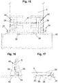
- Figure 11a shows an exemplary embodiment of a carrier device 1 in the installed state on a motor vehicle 2, the carrier device 1 being arranged in the rear area, more precisely under a loading floor of the trunk of the motor vehicle 2, via the fastening device 4 and being in the usage position 18.
- the carrier device 1 of this exemplary embodiment has a fastening device 4 for fastening to the motor vehicle.
- the carrier device can be moved between a use position 18 and a stowed position 17 (via rolling bodies 32) along the pull-out axis 7 via the guide device 6 .
- the carrier device In a stowage position 17 of this exemplary embodiment, the carrier device, more precisely the receiving devices 5 and the guide devices 6 , are completely sunk in the rear area of the motor vehicle 2 .
- the carrier device By pulling out the receiving devices 5 via the guide device 6 along the pull-out axis 7, the carrier device can be transferred into a use position 18, with the receiving devices 5 being able to be folded open about an axis transverse to the pull-out axis 7 when the guide device 6 is pulled out, in order to receive a bicycle 3 .
- a length of the guide device 6 and a number of the receiving devices 5 can be increased, depending on the lengthening of the carrier device 1, with several receiving devices 5 being able to be provided if the motor vehicle 2 has a longer receiving area for the carrier device 1.
- Figure 11b shows the embodiment of Figure 11a in the stowed position 17.
- the carrying device 1 can be arranged at any position between the vehicle underbody and the loading sill of the trunk.
- the guide device 6 for guiding the receiving device 5 has a carrier body 42 which can be moved along the pull-out axis 7 via the guide rails 31 .
- the receiving device 5 is mounted on the carrier body 42 via the hinge 27, with the receiving device 5 being able to be tilted relative to the carrier body 42 of the guiding device 6 about a tilting axis 35 transversely to the extension axis 7 and thus being able to be transferred into a use position 18.
- the usage position 18 of the receiving device 5 is assumed when the receiving device 5 hits the carrier body 42 of the guide device 6 by means of the stops 30 attached to the receiving device 5 due to the tilting transversely to the extraction axis 7 and thus assumes a position locked by 90° relative to the carrier body 42 ( how through 14 can be seen) .
- the recording device 5 of the embodiment of 12 has a height adjustment 28, wherein the V-shaped section 9 for receiving a crank 21 of a bicycle 3 can be adjusted in relation to the carrier body 42 in its distance to be able to be adjusted to different bicycle sizes.
- This height adjustment 28 occurs through an adjustment between the holding plate 36 (which receives the crank 21 of the bicycle 3) in relation to the base plate 46 (which attached to the carrier body 42 via the hinge 27) of the receiving device 5.
- This setting of the holding plate 36 relative to the base plate 46 is done by means of an adjustment using the bolts 37 which connect the holding plate 36 to the base plate 46.
- bores are arranged on the base plate 46, which have a grid in order to enable the holding plate 36 to be adjusted in different heights.
- the retaining plate 36 also has an electrically operated actuator 34 which is designed to close and/or release the receiving area for the crank 21 of the bicycle 3 indicated by dashed lines when the crank 21 of the bicycle 3 is positioned in the receiving area or is removed.
- This electrically operated actuator 34 thus represents the locking device 22 of this exemplary embodiment.
- the actuator 34 is designed as a so-called electric cylinder.
- holding bodies 52 are also optionally provided, which suppress any seesaw movements of the crank 21 and/or of the entire bicycle 3 .
- the variant of the 12 an electrical connection device 13, in which case, for example, electric bicycles (e-bikes) could be loaded when they take their place on the carrier device 1.
- electric bicycles e-bikes
- 15 - 17 show an exemplary embodiment in which locking can be carried out transversely to the pull-out axis 7 when the receiving device 5 is tilted relative to the guide device 6 (carrier body 42).
- the receiving device 5 is folded open via the hinges 27 until the stops 30 provided on the receiving device 5 come into contact with the carrier body 42 .
- the further stops 39 are provided, which are mounted on the receiving device 5 via the dovetail guide 40 .
- the further stops 39 are coupled to one another by the spring element 41 .
- the further stops 39 are located in the recesses 38 (as in 17 shown) their place and thus allow a complete folding of the receiving device 5 to the carrier body 42.
- the other stops 39 are spaced apart from each other by the spring element 41 as soon as they leave the recess 38, so that the stops 39 come into contact with the surface of the carrier body 42 and thus the receiving device 5 secure on both sides against tilting about the tilting axis 35 (as per 16 is shown).
- the further stops 39 can be pressed against one another, as a result of which the spring element 41 is braced and the further stops 39 can enter the recesses 38 again.
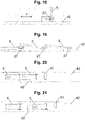
- the Figures 18 - 21 show different embodiment variants of several receiving devices 5 on a carrier body 42 of the guide device 6, wherein the receiving devices 5 are arranged tiltable relative to the guide device 6 by means of a hinge 27 transversely to the pull-out axis 7.
- the distance between the recording devices 5 can be designed differently from one another, as by the 20 and 21 is shown, whereby a crank width of a bicycle 3 is discussed individually can, in order to be able to accommodate wider or thinner bicycles on the carrier device 1 in a space-saving and uncomplicated manner.
- the receiving device 5 always receives one end of the crank, whereas the crank receptacle 43 in the carrier body 42 of the guide device 6 receives the other crank.
- This crank mount 43 is formed by a corresponding slot in the carrier body 42, with one crank of the bicycle finding its place in the crank mount 43 and the other crank of the bicycle 3 on the receiving device 5.
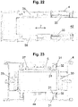
- the 22 and 23 show the carrier device 1 with its fastening device 4 and the guide device 6 in a detailed view.
- the fastening device 4 of this exemplary embodiment forms a box which accommodates the guide device 6 and the receiving device 5 in a stowed position 17 .
- the fastening device 4 can be connected to the vehicle 2 via fastening screws, bolts, welds or the like.
- the guide device 6 of this exemplary embodiment has guide rails 31 (see FIG 23 ), with one guide rail each being arranged on the fastening device 4 and the other guide rail 31 on a carrier body 42 on which the receiving devices 5 are mounted.
- Rolling bodies 32 are arranged between the guide rails 31 so that a relative movement of the two guide rails and thus of the receiving devices 5 with respect to the fastening device 4 is permitted.
- the carrier body 42 can be guided along the pull-out axis 7 with the aid of the guide rails 31 and the rolling bodies 32 in order to move the receiving devices between a use position 18 and a stowed position 17 .
- a locking device is provided, which is implemented by the clamping device 33 .
- This clamping device 33 can be pressed against the carrier body 42 via electrically operated actuators 34, as a result of which a clamping of the carrier body 42 with the fastening device 4 (similar to a shoe brake) is implemented via a frictional force.
- This clamping device 33 creates the possibility of locking the receiving devices 5 in various positions along the pull-out axis 7 in relation to the fastening body 4 in a freely selectable manner.
- a so-called electric cylinder can be used as the actuator 34, for example which presses the clamping jaws onto the receiving device via a lever.
- the electric cylinder can be locked in a locked position, so that energy does not have to be constantly used for clamping.
- a shaft 44 can be seen, via which the electrically operated actuators and/or other electrical consumers of the carrier device 1 can obtain their power supply or their electrical connection.
- the electrically actuated actuators 34 or vehicle lights 15 arranged on the carrier device 1 can be connected via the shaft 44 and/or cable harness 45 of the carrier device 1, such as by 24 is shown.
- this wiring harness 45 can be coupled to an electrical system of the motor vehicle, so that the actuators can supply an e-bike connection option or the motor vehicle lighting 15 of the carrier device 1 through the electrical motor vehicle system and the wiring harness 45 .
- FIG. 24 shows a plan view of an embodiment of a carrier device 1, the carrier device 1 being in a stowed position 17.
- FIG. 24 shows a plan view of an embodiment of a carrier device 1, the carrier device 1 being in a stowed position 17.
- the carrier body 42 of the guide device 6 and the receiving devices 5 are pushed into the box-shaped fastening device 4 .
- the motor vehicle lights 15 are folded in at the side and also drawn into the fastening device 4 .
- the receiving devices 5 are now pulled out of the fastening device 4 along the extraction axis 7 via the guide device 6 and are transferred into a use position 18, the receiving devices 5 can be tilted transversely to the extraction axis 7, for example by 25 is shown.
- the motor vehicle lights 15 can be swiveled out via the pivot points 47 in order to be converted into a use position.
- an inner tube 48 on which the motor vehicle lights 15 are arranged is moved via a bolt serving as a pivot point 47 in relation to an outer tube 49 arranged on the support body 42 of the guide device 6, with the pivot point 47 serving bolts in a guide link 50 of the outer tube 49 is moved, as by the 26 and 27 can be seen.
- fastening screws 51 are provided which can cause a clamping between the outer tube 49 and the inner tube 48 by tightening and loosening.
Landscapes
- Engineering & Computer Science (AREA)
- Mechanical Engineering (AREA)
- Fittings On The Vehicle Exterior For Carrying Loads, And Devices For Holding Or Mounting Articles (AREA)
Abstract
Trägervorrichtung für ein Kraftfahrzeug (2) zur Befestigung wenigstens eines Fahrrads (3), umfassend:- wenigstens eine Befestigungsvorrichtung (4) zur Anbindung der Trägervorrichtung (1) an das Kraftfahrzeug (2),- wenigstens eine relativ zur Befestigungsvorrichtung (4) bewegbare Aufnahmevorrichtung (5) zur Aufnahme des wenigstens einen Fahrrads (3) und- wenigstens eine Führungsvorrichtung (6), wobei die wenigstens eine Aufnahmevorrichtung (5) mittels der wenigstens einen Führungsvorrichtung (6) in Richtung einer Ausziehachse (7) der Trägervorrichtung (1) relativ zur wenigstens einen Befestigungsvorrichtung (4) zwischen einer Verstauposition (17) und wenigstens einer Gebrauchsposition (18) führbar ist,wobei die wenigstens eine Aufnahmevorrichtung (5) mittels der wenigstens einen Führungsvorrichtung (6) zwischen der Verstauposition (17) und der wenigstens einer Gebrauchsposition (18) zusätzlich durch eine Verkippung um die Ausziehachse (7) und/oder durch Klappen um eine Achse quer zur Ausziehachse (7) bewegbar ist.Carrier device for a motor vehicle (2) for fastening at least one bicycle (3), comprising: - at least one fastening device (4) for connecting the carrier device (1) to the motor vehicle (2), - at least one receiving device movable relative to the fastening device (4). (5) for accommodating the at least one bicycle (3) and at least one guide device (6), the at least one accommodating device (5) being relatively to the at least one fastening device (4) between a stowed position (17) and at least one use position (18), the at least one receiving device (5) being guided between the stowed position (17) and the at least one use position by means of the at least one guide device (6). (18) additionally by tilting about the pull-out axis (7) and/or by folding about an axis transverse to the Au sziehachse (7) is movable.
Description
Die vorliegende Erfindung betrifft eine Trägervorrichtung für ein Kraftfahrzeug zum Befestigen wenigstens eines Fahrrades mit den Merkmalen des Oberbegriffs des Anspruchs 1 sowie ein Kraftfahrzeug mit einer solchen Trägervorrichtung.The present invention relates to a carrier device for a motor vehicle for fastening at least one bicycle with the features of the preamble of
Kraftfahrzeuge können beispielsweise Personenkraftwagen, Lastkraftwagen oder andere Fahrzeuge zur Beförderung von Personen sein. Im Folgenden soll der Stand der Technik kurz anhand von Personenkraftwagen umrissen werden. Analoges gilt allgemein für Kraftfahrzeuge.Motor vehicles can be, for example, passenger cars, trucks or other vehicles for transporting people. In the following, the state of the art will be briefly outlined using passenger cars. The same applies in general to motor vehicles.
Gattungsgemäße Trägervorrichtungen umfassen:
- wenigstens eine Befestigungsvorrichtung zur Anbindung der Trägervorrichtung an ein Personenkraftfahrzeug,
- wenigstens eine relativ zur Befestigungsvorrichtung bewegbare Aufnahmevorrichtung zur Aufnahme des wenigstens einen Fahrrads, und
- wenigstens eine Führungsvorrichtung, wobei die wenigstens eine Aufnahmevorrichtung mittels der wenigstens einen Führungsvorrichtung in Richtung einer Ausziehachse der Trägervorrichtung relativ zur wenigstens einen Befestigungsvorrichtung zwischen einer Verstauposition und wenigstens einer Gebrauchsposition führbar ist.
- at least one fastening device for connecting the carrier device to a passenger vehicle,
- at least one receiving device, which is movable relative to the fastening device, for receiving the at least one bicycle, and
- at least one guide device, wherein the at least one receiving device can be guided by means of the at least one guide device in the direction of a pull-out axis of the carrier device relative to the at least one fastening device between a stowed position and at least one use position.
Entsprechende Trägervorrichtungen werden mit der wenigstens einen Befestigungsvorrichtung zumeist in einem hinteren Bereich des Personenkraftfahrzeuges an der Stoßstange oder unterhalb des Fahrzeuges angebunden. Die Anbindung kann über eine Schweiß- oder Schraubverbindung beispielsweise am Chassis des Fahrzeuges erfolgen.Corresponding carrier devices are connected to the at least one fastening device, mostly in a rear area of the passenger vehicle on the bumper or underneath the vehicle. The connection can be made via a welded or screwed connection can be made, for example, on the chassis of the vehicle.
Über die Führungsvorrichtung kann anschließend die Aufnahmevorrichtung, welche dazu ausgebildet ist, das wenigstens eine Fahrrad aufzunehmen, aus diesem unteren oder hinteren Bereich entlang einer Fahrtrichtung des Fahrzeugs ausgezogen werden, sodass sich die Trägervorrichtung in einer Verstauposition im hinteren Bereich oder unterhalb des Fahrzeugs versteckt und bei Gebrauch in eine Gebrauchsposition über die Führungsvorrichtung überführen lässt.The receiving device, which is designed to receive the at least one bicycle, can then be pulled out of this lower or rear area along a direction of travel of the vehicle via the guide device, so that the carrier device is hidden in a stowed position in the rear area or below the vehicle and at Use can be converted into a use position on the guide device.
Solche aus dem Stand der Technik bekannte Trägervorrichtungen gehen beispielsweise aus der
Nachteilig an solchen Trägervorrichtungen aus dem Stand der Technik ist jedoch, dass die Befestigungsvorrichtung einen relativ breiten und großen Bereich am Personenkraftfahrzeug einnimmt und dort auch eine entsprechende Halterung benötigt, sodass fahrzeugseitig ein recht großer Bereich für die Anbringung der Trägervorrichtung angepasst werden muss bzw. verlorengeht, welcher für Fahrzeugkomponenten, wie Fahrwerk, Antrieb oder Abgasanlage, erforderlich ist.A disadvantage of such carrier devices from the prior art, however, is that the fastening device takes up a relatively wide and large area on the passenger vehicle and also requires a corresponding holder there, so that a fairly large area for attaching the carrier device has to be adapted or is lost on the vehicle side. which is required for vehicle components such as chassis, drive or exhaust system.
Des Weiteren ist es nachteilig, dass in Gebrauchsposition der Trägervorrichtung im hinteren Bereich des Fahrzeuges rechtwinklig davon abstehende Befestigungsvorrichtungen (welche es benötigt, um ein Fahrrad beispielsweise über Halteklauen am Rahmen zu befestigen) vorgesehen sind, welche in einer Verstauposition die freie Zugänglichkeit des Fahrzeuges beeinträchtigt, sodass beispielsweise in vielen Fällen der Kofferraum nicht mehr öffenbar oder nur schwer zugänglich ist. Dies macht es zumeist erforderlich Teile der Tragvorrichtung zu demontieren, bevor die Trägervorrichtung in eine Verstauposition übergeführt wird.Furthermore, it is disadvantageous that the carrier device is in the rear area of the vehicle when it is in use fastening devices protruding at right angles (which are required, for example, to attach a bicycle to the frame via retaining claws) are provided, which in a stowed position impairs the free accessibility of the vehicle, so that in many cases, for example, the trunk can no longer be opened or is only accessible with difficulty. This usually makes it necessary to disassemble parts of the carrying device before the carrying device is transferred to a stowed position.
Diese Demontage von zusätzlichen Halteelementen der Trägervorrichtung macht es jedoch wieder erforderlich, diese demontierten Teile in der Verstauposition beispielsweise im Innenraum des Fahrzeuges oder an anderen Positionen zu lagern, was sich wiederum negativ auf die Bedienerfreundlichkeit für einen Anwender ausübt.However, this dismantling of additional holding elements of the carrier device again makes it necessary to store these dismantled parts in the stowage position, for example in the interior of the vehicle or at other positions, which in turn has a negative impact on the user-friendliness for a user.
Aufgabe der vorliegenden Erfindung ist es, eine Trägervorrichtung und ein Kraftfahrzeug mit einer solchen Trägervorrichtung bereitzustellen, welche zumindest teilweise die zuvor beschriebenen Nachteile des Standes der Technik verbessern und/oder eine Bedienerfreundlichkeit erhöhen und/oder einen geringeren Platzbedarf am Kraftfahrzeug darstellt.The object of the present invention is to provide a carrier device and a motor vehicle with such a carrier device which at least partially improves the disadvantages of the prior art described above and/or increases user-friendliness and/or requires less space on the motor vehicle.
Diese Aufgabe wird durch eine Trägervorrichtung mit den Merkmalen des Anspruchs 1 gelöst, sowie einem Kraftfahrzeug mit einer solchen Trägervorrichtung.This object is achieved by a carrier device having the features of
Erfindungsgemäß ist es somit vorgesehen, dass eine Trägervorrichtung folgendes umfasst:
- wenigstens eine Befestigungsvorrichtung zur Anbindung der Trägervorrichtung an das Kraftfahrzeug,
- wenigstens eine relativ zur Befestigungsvorrichtung bewegbare Aufnahmevorrichtung zur Aufnahme des wenigstens einen Fahrrads, und
- wenigstens eine Führungsvorrichtung, wobei die wenigstens eine Aufnahmevorrichtung mittels der wenigstens einen Führungsvorrichtung in Richtung einer Ausziehachse der Trägervorrichtung relativ zur wenigstens einen Befestigungsvorrichtung zwischen einer Verstauposition und
- at least one fastening device for connecting the carrier device to the motor vehicle,
- at least one receiving device, which is movable relative to the fastening device, for receiving the at least one bicycle, and
- at least one guide device, wherein the at least one receiving device by means of the at least one guide device in the direction of a pull-out axis of the carrier device relative to the at least one fastening device between a stowed position and
Durch das Verkippen um die Ausziehachse und/oder durch Klappen um eine Achse quer zur Ausziehachse bei der Bewegung zwischen der Gebrauchsposition und der Verstauposition der wenigstens einen Aufnahmevorrichtung wird es gestattet, dass von der wenigstens einen Aufnahmevorrichtung abstehende Konstruktionselemente (welche beispielsweise sonst in einer Verstauposition die Zugänglichkeit des Kraftfahrzeuges beeinträchtigen würden) umgeklappt werden und in einer Verstauposition nunmehr in einem Heckbereich oder unter einem Kraftfahrzeug verschwinden können, wodurch eine bessere Zugänglichkeit für einen Bediener gestattet wird. Des Weiteren ist es nun möglich, durch die Verkippung und/oder das Klappen der Trägervorrichtung die Trägervorrichtung weit effizienter und platzsparender an einem Kraftfahrzeug anzubringen, wobei die Trägervorrichtung in einer Verstauposition in einem verfügbaren Stauraum des Kraftfahrzeuges verdreht werden kann.By tilting about the pull-out axis and/or by folding about an axis transverse to the pull-out axis when moving between the usage position and the stowed position of the at least one receiving device, it is possible for structural elements protruding from the at least one receiving device (which, for example, would otherwise be in a stowed position, to Would affect accessibility of the motor vehicle) are folded over and can now disappear in a stowed position in a rear area or under a motor vehicle, which allows better accessibility for an operator. Furthermore, by tilting and/or folding the carrier device, it is now possible to attach the carrier device to a motor vehicle in a far more efficient and space-saving manner, with the carrier device being able to be rotated into a stowed position in an available storage space of the motor vehicle.
Eine erfindungsgemäße Vorrichtung kann auch ihren Einsatz in bereits bekannten Ausführungsvarianten des Standes der Technik, wie beispielsweise auch durch die Beschreibungseinleitung beschrieben, ihren Einsatz finden und nachträglich installiert werden.A device according to the invention can also be used in already known design variants of the prior art, as also described, for example, by the introduction to the description, and can be installed subsequently.
In besonders bevorzugten Ausführungsformen kann das wenigstens eine Fahrrad beispielsweise mit arretierter Kurbel zwischen Rahmen und Kurbel des Fahrrads in der klappbare Aufnahmevorrichtung aufgenommen werden.In particularly preferred embodiments, the at least one bicycle can be accommodated in the foldable accommodation device, for example with the crank locked between the frame and the crank of the bicycle.
Vorteilhafte Ausführungsformen der Erfindung sind anhand der abhängigen Ansprüche definiert.Advantageous embodiments of the invention are defined by the dependent claims.
Vorzugsweise kann vorgesehen sein, dass wenn eine Vielzahl von Aufnahmevorrichtungen vorgesehen sind, dass jede Aufnahmevorrichtungen separat zwischen der Verstauposition und wenigstens einer Gebrauchsposition durch eine Verkippung um die Ausziehachse und/oder durch Klappen um eine Achse quer zur Ausziehachse bewegbar ist.If a plurality of holding devices are provided, it can preferably be provided that each holding device can be moved separately between the stowed position and at least one use position by tilting about the pull-out axis and/or by folding about an axis transverse to the pull-out axis.
Die erfindungsgemäße Verkippung des wenigstens einen Aufnahmeelements kann über einen Winkel von mehr als 30°, bevorzugt mehr als 60° und besonders bevorzugt mehr als 80°, reichen. In besonders bevorzugten Ausführungsformen kann die Verkippung im Wesentlichen über einen 90°-Winkel reichen.The tilting according to the invention of the at least one receiving element can be over an angle of more than 30°, preferably more than 60° and particularly preferably more than 80°. pass. In particularly preferred embodiments, the tilting can extend essentially over a 90° angle.
Es kann vorgesehen sein, dass die wenigstens eine Aufnahmevorrichtung eine Längserstreckung aufweist, wobei ein Winkel zwischen der Längserstreckung und der Ausziehachse zwischen 45° und 90°, vorzugsweise genau 90°, beträgt.Provision can be made for the at least one receiving device to have a longitudinal extent, with an angle between the longitudinal extent and the pull-out axis being between 45° and 90°, preferably exactly 90°.
Durch die mit einem Winkel abstehende Längserstreckung kann eine L-förmige Ausgestaltung der Ausziehvorrichtung vorgenommen werden, wobei das "L" bei einer Überführung zwischen Gebrauchsposition und Verstauposition umgeklappt wird.Due to the longitudinal extension protruding at an angle, an L-shaped configuration of the pull-out device can be undertaken, with the "L" being folded over during a transfer between the use position and the stowed position.
Es kann vorgesehen sein, dass die wenigstens eine Aufnahmevorrichtung zusätzlich um eine, vorzugsweise verstellbare, Querachse zur Ausziehachse klappbar mit der wenigstens einen Führungsvorrichtung verbunden ist. Dadurch kann die wenigstens eine Aufnahmevorrichtung in der Gebrauchsposition von der Führungsvorrichtung in einem rechten Winkel abstehen und sich in der Verstauposition an die Führungsvorrichtung anlegen. Dadurch kann in der Verstauposition am oder im Fahrzeug noch mehr Platz gespart werden.It can be provided that the at least one receiving device is additionally connected to the at least one guide device such that it can be folded about a, preferably adjustable, transverse axis to the pull-out axis. As a result, the at least one receiving device can protrude from the guide device at a right angle in the use position and can rest against the guide device in the stowed position. As a result, even more space can be saved in the stowage position on or in the vehicle.
Vorzugsweise ist vorgesehen, dass die wenigstens eine Aufnahmevorrichtung durch Klappen um eine Achse quer zur Ausziehachse in eine Gebrauchsposition überführbar ist, wobei die wenigstens eine Aufnahmevorrichtung durch wenigstens eine Sperrvorrichtung, vorzugsweise wenigstens einen Anschlag, in der Gebrauchsposition gegenüber einer Verkippung lösbar verriegelbar ist.It is preferably provided that the at least one receiving device can be converted into a use position by folding about an axis transverse to the pull-out axis, the at least one receiving device being secured by at least one locking device, preferably at least a stop which can be releasably locked against tilting in the use position.
Es kann vorgesehen sein, dass die wenigstens eine Aufnahmevorrichtung einen U- oder V-förmigen Abschnitt aufweist, welcher U- oder V-förmige Abschnitt vorzugsweise dazu ausgebildet ist, ein Pedal und/oder eine Kurbel des wenigstens einen Fahrrads aufzunehmen.Provision can be made for the at least one receiving device to have a U-shaped or V-shaped section, which U-shaped or V-shaped section is preferably designed to accommodate a pedal and/or a crank of the at least one bicycle.
Durch einen U- oder V-förmigen Abschnitt kann es beispielsweise vorgesehen sein, dass die Aufnahmevorrichtung einen U- oder V-förmigen Ausschnitt aufweist, wobei am Scheitelpunkt des U- oder V-förmigen Ausschnittes ein Pedal oder eine Kurbel des wenigstens einen Fahrrads einrasten kann oder befestigt werden kann, um mit der Trägervorrichtung transportiert werden zu können.A U-shaped or V-shaped section can, for example, provide for the receiving device to have a U-shaped or V-shaped cutout, with a pedal or crank of the at least one bicycle being able to engage at the apex of the U-shaped or V-shaped cutout or can be attached to be transported with the carrier device can.
Insbesondere wenn dieser U- oder V-förmige Abschnitt nach oben weist, kann dadurch eine besonders einfache Montage des wenigstens einen Fahrrads ermöglicht werden, wobei das wenigstens einen Fahrrad nur von oben in den U- oder V-förmigen Abschnitt hineingehoben werden kann und dadurch sofort gehalten wird, ohne dass eine montierende Person das Gewicht des Fahrrads weiter halten müsste. Durch die erfindungsgemäße Anordnung der Trägervorrichtung in oder unter einer Stoßstange muss das wenigstens eine Fahrrad gleichzeitig nicht sehr hoch gehoben werden.In particular, if this U- or V-shaped section points upwards, a particularly simple assembly of the at least one bicycle can thereby be made possible, the at least one bicycle being able to be lifted into the U- or V-shaped section only from above and thereby immediately is held without a assembling person having to continue holding the weight of the bicycle. Due to the arrangement of the carrier device according to the invention in or under a bumper, the at least one bicycle does not have to be lifted very high at the same time.
Es kann vorgesehen sein, dass die wenigstens eine Aufnahmevorrichtung durch wenigstens eine Höhenverstellung relativ zu der wenigstens einen Befestigungsvorrichtung verstellbar ist.Provision can be made for the at least one receiving device to be adjustable by at least one height adjustment relative to the at least one fastening device.
Durch Vorsehen wenigstens einer Höhenverstellung kann es beispielsweise vorgesehen sein, dass die wenigstens eine Aufnahmevorrichtung, gegenüber der wenigstens einen Befestigungsvorrichtung in einem montierten Zustand an einem Kraftfahrzeug in einer Höhe verstellt werden kann.By providing at least one height adjustment, it can be provided, for example, that the height of the at least one receiving device can be adjusted relative to the at least one fastening device in a mounted state on a motor vehicle.
Dies kann beispielsweise dazu dienen, dass die wenigstens eine Aufnahmevorrichtung in einer Gebrauchsposition zur Befestigung des wenigstens einen Fahrrads abgesenkt werden kann, sodass der Anwender das Fahrrad nicht zu weit anheben muss. Anschließend kann es vorgesehen sein die wenigstens eine Aufnahmevorrichtung in der Gebrauchsposition mittels der wenigstens eine Höhenverstellung angehoben werden kann, sodass die wenigstens eine Aufnahmevorrichtung (und ein daran beispielsweise befestigtes Fahrrad), insbesondere währen des Transportes durch das Kraftfahrzeug eine höhere Position gegenüber einem Untergrund einnimmt.This can be used, for example, to allow the at least one receiving device to be lowered in a usage position for fastening the at least one bicycle, so that the user does not have to lift the bicycle too far. It can then be provided that the at least one receiving device can be raised in the use position by means of the at least one height adjustment device, so that the at least one receiving device (and a bicycle attached to it, for example) assumes a higher position relative to the ground, in particular during transport by the motor vehicle.
Vorzugsweise kann vorgesehen sein, dass wenigstens ein Klemmelement zum klemmenden Halten des wenigstens einen Fahrrads vorgesehen ist, vorzugsweise in Form wenigstens einer Halteklaue.Provision can preferably be made for at least one clamping element to be provided for clampingly holding the at least one bicycle, preferably in the form of at least one holding claw.
Es kann vorgesehen sein, dass wenigstens eine lösbare Verbindungsvorrichtung, vorzugsweise mindestens ein abnehmbares und/oder klappbares (und somit beispielweise verstaubares) Verbindungsrohr, zum Montieren des wenigstens einen Klemmelementes an der wenigstens einen Aufnahmevorrichtung vorgesehen ist.It can be provided that at least one detachable connecting device, preferably at least one removable and/or foldable (and thus e.g. stowable) connecting tube, is provided for mounting the at least one clamping element on the at least one receiving device.
Alternativ oder zusätzlich kann auch vorgesehen sein, dass wenigstens ein Klemmelementes klappbar an der wenigstens einen Aufnahmevorrichtung vorgesehen ist, wobei das wenigstens ein Klemmelement in der Gebrauchsposition an das wenigstens eine Fahrrad herangeklappt werden kann und in der Verstauposition an die wenigstens einen Aufnahmevorrichtung und/oder and die wenigstens eine Befestigungsvorrichtung abgeklappt werden.Alternatively or additionally, it can also be provided that at least one clamping element is foldable on the at least one receiving device, wherein the at least one clamping element can be folded onto the at least one bicycle in the use position and onto the at least one receiving device and/or others in the stowed position the at least one fastening device can be folded down.
So kann es beispielsweise vorgesehen sein, dass die Verbindungsvorrichtung eine Ausnehmung beinhaltet, in welcher beispielsweise ein rohr- oder stangenähnliches Element befestigt werden kann, an welchem das Klemmelement angeordnet ist (beispielweise eine Halteklaue).For example, it can be provided that the connecting device includes a recess in which, for example, a tube or rod-like element can be fastened, on which the clamping element is arranged (for example, a holding claw).
Es kann vorgesehen sein, dass die wenigstens eine Führungsvorrichtung ineinander geführte Rohre beinhaltet. So kann beispielsweise vorgesehen sein, dass das äußere oder das innere Rohr einen Führungszapfen aufweist, welcher beispielsweise in einer Führungskulisse am anderen Rohr geführt ist, wobei die (beispielsweise L-förmige) Führungskulisse den Zapfen bereits zwischen einer Verstauposition und einer Gebrauchsposition führt, wobei eine Rotationsbewegung beinhaltet ist.Provision can be made for the at least one guiding device to contain tubes guided into one another. For example, it can be provided that the outer or inner tube has a guide pin, which is guided, for example, in a guide link on the other tube, with the (e.g. L-shaped) guide link already guiding the pin between a stowed position and a use position, with one Rotational movement is included.
Es kann beispielsweise auch vorgesehen sein, dass die wenigstens eine Führungsvorrichtung nur teilweise ineinander geführte Rohre aufweist, um eine entsprechende Verkippung umzusetzen, wobei ein weiterer ein weiterer Teil der Führungsvorrichtung durch ineinander geführte, vorzugsweise mit rechteckigem Querschnitt ausgebildete, Rohre umgesetzt ist, um die Ausziehbewegung umzusetzen.Provision can also be made, for example, for the at least one guide device to have tubes that are only partially guided into one another in order to implement a corresponding tilting, with another part of the guide device being converted by tubes that are guided into one another and are preferably designed with a rectangular cross section, in order to achieve the pull-out movement implement.
Vorzugsweise kann vorgesehen sein, dass die wenigstens eine Führungsvorrichtung wenigstens eine Führungsschiene und wenigstens einen mit der wenigstens einen Führungsschiene kooperierenden Rollkörper aufweist.Provision can preferably be made for the at least one guide device to have at least one guide rail and at least one rolling body which cooperates with the at least one guide rail.
Es kann die wenigstens eine Führungsschien oder der wenigstens eine Rollkörper mit der Befestigungsvorrichtung und/oder Aufnahmevorrichtung bewegungsschlüssig in Richtung der Ausziehachse verbunden sein, wobei über eine Relativbewegung zwischen Führungsschien und Rollkörper die Aufnahmevorrichtung gegenüber der Befestigungsvorrichtung zwischen der Verstauposition und der Gebrauchsposition bewegbar ist.The at least one guide rail or the at least one rolling body can be connected to the fastening device and/or receiving device in a motion-locked manner in the direction of the extension axis, with the receiving device being movable relative to the fastening device between the stowed position and the use position via a relative movement between the guide rail and rolling body.
Vorzugsweis kann auch vorgesehen sein, dass wenigstens zwei Führungsschienen und wenigstens ein zwischen den wenigstens zwei Führungsschienen angeordneter Rollkörper, besonders bevorzugt wenigstens ein Wälzkörper, vorgesehen sind. Dabei kann es vorgesehen sein, dass eine der wenigstens zwei Führungsschienen mit der Befestigungsvorrichtung und die andere der wenigstens zwei Führungsschienen mit der Aufnahmevorrichtung bewegungsschlüssig relativ zur Ausziehachse verbunden ist, wobei eine Bewegung der wenigstens zwei Führungsschienen zueinander über den wenigstens einen Rollköper gestattet wird (ähnlich einer Schubladenausziehführung) .Preferably, it can also be provided that at least two guide rails and at least one rolling body arranged between the at least two guide rails, particularly preferably at least one rolling body, are provided. Provision can be made for one of the at least two guide rails to be connected to the fastening device and the other of the at least two guide rails to be connected to the receiving device in a non-moving manner relative to the pull-out axis, with movement of the at least two guide rails relative to one another being permitted via the at least one rolling body (similar to a drawer slide) .
Es kann vorgesehen sein, dass wenigstens eine elektrische Verbindungsleitung vorgesehen ist, welche elektrische Verbindungsleitung dazu ausgebildet ist, ein E-Bike mit einer Stromquelle des Kraftfahrzeugs zu verbinden.It can be provided that at least one electrical connecting line is provided, which electrical connecting line is designed to To connect e-bike to a power source of the motor vehicle.
Vorzugsweise ist vorgesehen, dass die wenigstens eine Aufnahmevorrichtung gegenüber der wenigstens einen Befestigungsvorrichtung mittels einer Arretiervorrichtung, vorzugsweise wenigstens einer Klemmvorrichtung, in der Verstauposition und/oder in der wenigstens einen Gebrauchsposition, vorzugsweise jeder Gebrauchsposition, arretierbar ist.It is preferably provided that the at least one receiving device can be locked in relation to the at least one fastening device by means of a locking device, preferably at least one clamping device, in the stowage position and/or in the at least one use position, preferably any use position.
Die wenigstens eine Klemmvorrichtung kann beispielsweise wenigstens eine, vorzugsweise durch einen Aktuator betätigte, Klemmbacke aufweisen, wobei durch Kraftbeaufschlagung der wenigstens einen Klemmbacke gegenüber einem korrespondierendem Gegenstück die Aufnahmevorrichtung gegenüber der Befestigungsvorrichtung über eine Klemmkraft (und eine daraus resultierende Reibkraft - ähnlich einer Backenbremse) arretierbar ist. der Aktuator zur Betätigung der wenigstens einen Klemmvorrichtung kann beispielsweise elektrisch oder auch hydraulisch betätigt ausgebildet sein.The at least one clamping device can, for example, have at least one clamping jaw, preferably actuated by an actuator, wherein by applying force to the at least one clamping jaw relative to a corresponding counterpart, the receiving device can be locked relative to the fastening device via a clamping force (and a resulting frictional force - similar to a shoe brake). . the actuator for actuating the at least one clamping device can, for example, be designed to be electrically or hydraulically actuated.
Es kann auch vorgesehen sein, dass die wenigstens eine Aufnahmevorrichtung gegenüber der wenigstens einen Befestigungsvorrichtung in mehreren Positionen (abgesehen von der Verstauposition und der wenigstens einen Gebrauchsposition) arretierbar ist.Provision can also be made for the at least one receiving device to be lockable in a number of positions (apart from the stowage position and the at least one use position) relative to the at least one fastening device.
Eine solche Arretiervorrichtung kann beispielsweise auch durch einen Bolzen vorgesehen sein, welcher eine Bewegung der Führungsvorrichtung in der Gebrauchs- oder der Verstauposition verhindert. Alternativ kann es jedoch auch vorgesehen sein, dass die Arretierung durch Endlagen der Führungsvorrichtung gegeben ist. So kann es beispielsweise vorgesehen sein, dass - wenn die Führungsvorrichtung eine Führungskulisse beinhaltet - die Endpositionen bereits eine Arretierung zwischen Befestigungsvorrichtung und Aufnahmevorrichtung hervorrufen.Such a locking device can also be provided, for example, by a bolt which allows movement of the guide device in the use or the Stowage position prevented. Alternatively, however, it can also be provided that the locking is provided by the end positions of the guide device. For example, it can be provided that--if the guide device includes a guide link--the end positions already bring about a locking between the fastening device and the receiving device.
Es kann vorgesehen sein, dass wenigstens ein Antrieb vorgesehen ist, wobei der wenigstens eine Antrieb dazu ausgebildet ist, die wenigstens eine Aufnahmevorrichtung zwischen der Verstauposition und der wenigstens einen Gebrauchsposition zu bewegen.It can be provided that at least one drive is provided, wherein the at least one drive is designed to move the at least one receiving device between the stowed position and the at least one use position.
Hierzu kann es auch beispielsweise vorgesehen sein, dass die Trägervorrichtung, insbesondere die Antriebseinheit, mit dem Kraftfahrzeugsystem verbunden wird, wobei der wenigstens eine Antrieb über die Bedienung des Kraftfahrzeuges angesteuert werden könnte, um die wenigstens eine Aufnahmevorrichtung zwischen der Verstauposition und der wenigstens einen Gebrauchsposition zu bewegen.For this purpose, it can also be provided, for example, that the carrier device, in particular the drive unit, is connected to the motor vehicle system, in which case the at least one drive could be controlled via the operation of the motor vehicle in order to move the at least one receiving device between the stowed position and the at least one use position move.
Dies kann beispielsweise durch eine Bedieneinheit im Kraftfahrzeug oder auch eine Funkfernbedienung (ähnlich einer Autofernbedienung für die Zentralverriegelung) durchgeführt werden.This can be done, for example, by an operating unit in the motor vehicle or a radio remote control (similar to a car remote control for the central locking).
Vorzugsweise ist vorgesehen, dass an einem in der Gebrauchsposition von der wenigstens einen Befestigungsvorrichtung abgewandten Ende der wenigstens einen Aufnahmevorrichtung
- eine Kennzeichenhalterung und/oder
- wenigstens eine Kraftfahrzeugbeleuchtung, und/oder
- wenigstens eine Warnvorrichtung vorgesehen ist.
- a license plate holder and/or
- at least one motor vehicle light, and/or
- at least one warning device is provided.
Durch das Anordnen einer Kennzeichenhalterung an dem abgewandten Ende der wenigstens einen Aufnahmevorrichtung von der Befestigungsvorrichtung kann beispielsweise ein Kennzeichen mit der Trägervorrichtung mitbewegt werden und es ist nicht mehr erforderlich, dieses separat vom Fahrzeug abzunehmen und an einem Fahrradträger anzuordnen. Selbiges gilt natürlich auch für die Fahrzeugbeleuchtung oder eine Warnvorrichtung (wie beispielsweise Katzenaugen).By arranging a license plate holder at the end of the at least one receiving device facing away from the fastening device, for example, a license plate can be moved with the carrier device and it is no longer necessary to remove it separately from the vehicle and to arrange it on a bicycle carrier. The same applies, of course, to the vehicle lighting or a warning device (such as a cat's eyes).
Ebenfalls wird Schutz begehrt für ein Fahrrad umfassend wenigstens eine Kurbel und/oder wenigstens einen Lenker, wobei das Fahrrad wenigstens eine Feststellvorrichtung aufweist, welche wenigstens eine Feststellvorrichtung dazu ausgebildet ist, die Kurbel und/oder einen Lenker des wenigstens einen Fahrrads verdrehsicher, vorzugsweise bewegungsstarr, lösbar zu arretieren.Protection is also sought for a bicycle comprising at least one crank and/or at least one handlebar, the bicycle having at least one locking device, which at least one locking device is designed to prevent the crank and/or a handlebar of the at least one bicycle from twisting, preferably motionally rigid, to lock releasably.
Schutz wird ebenfalls begehrt für eine Anordnung einer erfindungsgemäßen Trägervorrichtung und wenigstens einem erfindungsgemäßen Fahrrad.Protection is also sought for an arrangement of a carrier device according to the invention and at least one bicycle according to the invention.
Weiters wird Schutz begehrt für ein Kraftfahrzeug mit einer erfindungsgemäßen Trägervorrichtung, wobei die Trägervorrichtung über die wenigstens eine Befestigungsvorrichtung am Kraftfahrzeug - vorzugsweise an einem Fahrgestell des Kraftfahrzeugs - angebunden ist. Vorzugsweise kann dabei vorgesehen sein, dass die Trägervorrichtung in einem in Fahrtrichtung hinteren Bereich des Kraftfahrzeugs angeordnet ist, wobei die wenigstens eine Aufnahmevorrichtung in der Verstauposition der Trägervorrichtung in oder unter eine Stoßstange des Kraftfahrzeuges zurückgezogen ist und in der wenigstens einen Gebrauchsposition von der Stoßstange des Kraftfahrzeugs in Fahrtrichtung beabstandet ist.Furthermore, protection is sought for a motor vehicle with a carrier device according to the invention, the carrier device being connected to the motor vehicle, preferably to a chassis of the motor vehicle, via the at least one fastening device. Provision can preferably be made for the carrier device to be arranged in a rear area of the motor vehicle in the direction of travel, with the at least one receiving device being retracted into or under a bumper of the motor vehicle when the carrier device is in the stowed position and by the bumper of the motor vehicle in the at least one use position is spaced in the direction of travel.
In bevorzugten Ausführungsformen kann die Trägervorrichtung in das Fahrzeug integriert sein.In preferred embodiments, the carrier device can be integrated into the vehicle.
Weitere Beispiele, Vorteile und Einzelheiten der Erfindung sind in den Figuren und der nachstehenden Figurenbeschreibung dargestellt. Darin zeigt
- Fig. 1
- ein erstes Ausführungsbeispiel einer erfindungsgemäßen Trägervorrichtung,
- Fig. 2
- eine Draufsicht auf
Fig. 1 in der Gebrauchsposition, - Fig. 3
- ein weiteres Ausführungsbeispiel einer erfindungsgemäßen Trägervorrichtung,
- Fig. 4
- eine Detailansicht einer Aufnahmevorrichtung,
- Fig. 5
- eine Draufsicht auf die
Fig. 4 , - Fig. 6
- eine Ausführungsvariante einer erfindungsgemäßen Trägervorrichtung mit einem Fahrrad
- Fig. 7
- ein Ausführungsbeispiel einer Führungsvorrichtung,
- Fig. 8
- ein zweites Ausführungsbeispiel einer erfindungsgemäßen Trägervorrichtung,
- Fig. 9
- eine Detailansicht einer Aufnahmevorrichtung,
- Fig. 10
- eine Draufsicht auf die
Fig. 9 . - Fig. 11 a, b
- eine Trägervorrichtung an einem Kraftfahrzeug,
- Fig. 12
- ein weiteres Ausführungsbeispiel einer erfindungsgemäßen Trägervorrichtung,
- Fig. 13
- eine Detailansicht der
Fig. 12 , - Fig. 14
- eine Detailansicht der
Fig. 12 , - Fig. 15
- eine Detailansicht einer Aufnahmevorrichtung,
- Fig. 16
- eine Detailansicht der
Fig. 15 , - Fig. 17
- eine Detailansicht der
Fig. 15 , - Fig. 18
- ein Ausführungsbeispiel einer Trägervorrichtung,
- Fig. 19
- ein Ausführungsbeispiel einer Trägervorrichtung,
- Fig. 20
- ein Ausführungsbeispiel einer Trägervorrichtung,
- Fig. 21
- ein Ausführungsbeispiel einer Trägervorrichtung,
- Fig. 22
- ein Ausführungsbeispiel einer Trägervorrichtung,
- Fig. 23
- eine Detailansicht der
Fig. 22 , - Fig. 24
- ein Ausführungsbeispiel einer Trägervorrichtung,
- Fig. 25
- ein Ausführungsbeispiel einer Trägervorrichtung,
- Fig. 26
- eine Detailansicht der
Fig. 25 , und - Fig. 27
- eine Detailansicht der
Fig. 25 ,
- 1
- a first embodiment of a carrier device according to the invention,
- 2
- a
top view 1 in the use position, - 3
- a further exemplary embodiment of a carrier device according to the invention,
- 4
- a detailed view of a recording device,
- figure 5
- a top view of the
4 , - 6
- an embodiment of a carrier device according to the invention with a bicycle
- 7
- an embodiment of a guiding device,
- 8
- a second embodiment of a carrier device according to the invention,
- 9
- a detailed view of a recording device,
- 10
- a top view of the
9 . - Fig. 11a, b
- a carrier device on a motor vehicle,
- 12
- a further exemplary embodiment of a carrier device according to the invention,
- 13
- a detailed view of
12 , - 14
- a detailed view of
12 , - 15
- a detailed view of a recording device,
- 16
- a detailed view of
15 , - 17
- a detailed view of
15 , - 18
- an embodiment of a carrier device,
- 19
- an embodiment of a carrier device,
- 20
- an embodiment of a carrier device,
- 21
- an embodiment of a carrier device,
- 22
- an embodiment of a carrier device,
- 23
- a detailed view of
22 , - 24
- an embodiment of a carrier device,
- 25
- an embodiment of a carrier device,
- 26
- a detailed view of
25 , and - 27
- a detailed view of
25 ,
Genau genommen ist die Trägervorrichtung 1 in einem in Fahrtrichtung 16 hinteren Bereich des Kraftfahrzeugs 2 angeordnet. Die Aufnahmevorrichtung 5 ist in einer Verstauposition 17 der Trägervorrichtung 1 in eine Stoßstange des Kraftfahrzeugs 2 zurückgezogen.Strictly speaking, the
Über die Führungsvorrichtung 6 der Trägervorrichtung 1 kann die Aufnahmevorrichtung 5 zwischen einer Verstauposition 17 und einer Gebrauchsposition 18 bewegt werden, wobei die Führungsvorrichtung 6 dermaßen ausgebildet ist, dass die Aufnahmevorrichtung 5 gegenüber dem Kraftfahrzeug 2 entlang einer Ausziehachse 7 (welche in diesem Ausführungsbeispiel mit der Fahrrichtung 16 des Kraftfahrzeugs 2 übereinstimmt) in eine Gebrauchsposition 18 ausgezogen wird, wobei die Aufnahmevorrichtung 5 nach dem Ausziehen zwischen der Verstauposition 17 und der Gebrauchsposition 18 durch ein Verkippen um die Ausziehachse 7 bewegbar ist (wie es durch die als Pfeil verdeutlichte Bewegung in
Die Befestigungsvorrichtung 4 der Trägervorrichtung 1 hält die Trägervorrichtung 1 am Kraftfahrzeug 2 und kann durch eine Verschraubung oder Verschweißung am Fahrgestell des Kraftfahrzeugs 2 angebunden werden.The
Die Aufnahmevorrichtung 5 ist dazu ausgebildet, wenigstens ein Fahrrad 3 aufzunehmen, wie in den folgenden Figuren noch näher erläutert wird.The receiving
Die Führungsvorrichtung 6 dieses Ausführungsbeispiels ist durch zwei ineinander geführte Rohre ausgebildet, wobei die Aufnahmevorrichtung 5 gegenüber der Befestigungsvorrichtung 4 geführt wird.The
Schön ersichtlich ist in dieser Figur, dass durch die Verkippung der Aufnahmevorrichtung 5 in eine Verstauposition 17 diese entlang der Stoßstange des Kraftfahrzeugs 2 "umgelegt" werden kann, sodass sie in der Verstauposition 17 im oder am Fahrzeug weniger Platz einnimmt oder einem Bediener nicht im Weg steht, wenn dieser beispielsweise den Kofferraumdeckel des Kraftfahrzeugs 2 öffnet.This figure clearly shows that by tilting the receiving
Durch das Verkippen der Aufnahmevorrichtung 5 um die Ausziehachse 7 kann die Aufnahmevorrichtung in einer Gebrauchsposition 18 zur Aufnahme eines Fahrrades 3 positioniert werden.By tilting the receiving
Weiters ist in
Diese klappbaren Signalelemente 20 können relativ zur Ausziehachse 7 um 90° aufgeklappt werden (wie durch die Pfeile gekennzeichnet ist) und tragen die Kraftfahrzeugbeleuchtung 15 (beispielsweise Blinker, Rückleuchten oder Bremslichter).These foldable signal
Des Weiteren ist an dem von der Befestigungsvorrichtung 4 abgewandten Ende der Aufnahmevorrichtung 5 eine Kennzeichenhalterung 14 vorgesehen, welche mitsamt der Aufnahmevorrichtung 5 über die Führungsvorrichtung 6 relativ zur Befestigungsvorrichtung 4 ausgezogen und aufgeklappt werden kann.Furthermore, a
Die Signalelemente 20 können beim Überführen zwischen der Gebrauchsposition in die Verstauposition (wie durch die Pfeile dargestellt) an die Aufnahmevorrichtung 5 angeklappt werden und mit dieser gemeinsam in den hinteren Bereich des Kraftfahrzeugs (oder auch unter das Kraftfahrzeug) verschoben werden, sodass sie in der Verstauposition 17 für einen Betrachter versteckt sind.The
Die vier Aufnahmevorrichtungen 5 sind Teil einer gemeinsamen Tragstruktur, welche die Aufnahmevorrichtungen 5 mit der Führungsvorrichtung 6 verbinden.The four
Weiters weist jede Aufnahmevorrichtung 5 Verbindungsvorrichtungen 12 auf, welche Klemmelemente 10 zur Befestigung der Fahrräder 3 aufnehmen können (hierzu noch weitere Details in den folgenden Figuren).Furthermore, each holding
Es ist ersichtlich, wie in diesem Ausführungsbeispiel die Fahrtrichtung 16 des Kraftfahrzeugs 2 mit der Ausziehachse 7 der Trägervorrichtung 1 übereinstimmt.It can be seen how the direction of
Die Trägervorrichtung 1 dieses Ausführungsbeispiels der
Weiters wird diese elektrische Verbindungsleitung 13 dazu genutzt, an der Trägervorrichtung 1 für E-Bikes eine Stromquelle bereitzustellen, die mit der Stromquelle des Kraftfahrzeugs 2 verbunden ist, sodass E-Bikes über die Trägervorrichtung 1 (beispielsweise während des Transportes des E-Bikes) geladen werden können.Furthermore, this electrical connecting
Die Aufnahmevorrichtungen 5 dieses Ausführungsbeispiels sind durch eine Arretiervorrichtung in einer Verstauposition 17 und einer Gebrauchsposition 18 arretierbar, wobei es auch beispielsweise vorgesehen sein kann, dass mehrere Gebrauchspositionen 18 vorgesehen sind, sodass immer nur eine Aufnahme für ein Fahrrad 3 aus dem Heck des Kraftfahrzeuges heraussteht, welche für den Einsatz gerade benötigt ist.The receiving
So kann es vorgesehen sein, dass die Trägervorrichtung je nach Bedarf nur für ein, zwei, drei oder vier Fahrräder 3 herausgezogen wird und in einer Gebrauchsposition 18 arretiert wird.Provision can thus be made for the carrier device to be pulled out for only one, two, three or four
Die Arretierung kann beispielsweise durch einen Bolzen erfolgen, welcher eine Bewegung der Führungsvorrichtung 6 hemmt, indem er die ineinander geführten Rohre durch entsprechend angeordnete Bohrungen durchtritt und somit eine Bewegung zwischen Aufnahmevorrichtung 5 und Befestigungsvorrichtung 4 hemmt.The locking can be effected, for example, by a bolt, which inhibits a movement of the
Des Weiteren kann jedoch auch vorgesehen sein, dass ein Antrieb vorgesehen ist, welcher Antrieb die Aufnahmevorrichtung zwischen einer Verstauposition 17 und einer Gebrauchsposition 18 bewegt. Dieser Antrieb kann durch eine Blockade ebenfalls als Arretiervorrichtung genutzt werden.Furthermore, however, it can also be provided that a drive is provided, which drive moves the receiving device between a stowed
Jedoch ist es auch vorstellbar, dass die Führungsvorrichtung eine Führungskulisse 25 aufweist, in welcher ein Führungszapfen 26 geführt wird, wobei an den Endlagen (oder auch in Zwischenlagen) der Führungskulisse 25 Arretierpositionen vorgesehen sind, sodass die Aufnahmevorrichtung 5 in einer Gebrauchsposition 18 und einer Verstauposition 17 arretierbar ist.However, it is also conceivable for the guide device to have a
Die weiteren Details dieser Trägervorrichtung 1 (beispielsweise Kennzeichenhalterung 14, Kraftfahrzeugbeleuchtung 15 oder Signalelemente 20) ähneln denen der bereits erläuterten zu
Diese Aufnahmevorrichtung 5 ist durch eine Verschweißung auf die Führungsvorrichtung 6 der Trägervorrichtung 1 aufgesetzt und erstreckt sich in einem rechten Winkel zu dieser.This receiving
Zur Stabilisierung der Aufnahmevorrichtung 5 sind des weiteren Versteifungselementes 19 vorgesehen.To stabilize the receiving
Alternativ könnte es jedoch auch vorgesehen sein, dass die Aufnahmevorrichtung 5 klappbar gegenüber der Führungsvorrichtung 6 (beispielsweise durch Scharniere) ausgebildet ist, sodass die Aufnahmevorrichtung 5 zusätzlich um eine Querachse zur Ausziehachse 7 zwischen der Gebrauchsposition 18 und der Verstauposition 17 umgeklappt werden kann, wobei die Aufnahmevorrichtung 5 in der Gebrauchsposition 18 von der Führungsvorrichtung 6 in einem rechten Winkel absteht und sich in der Verstauposition 17 an die Führungsvorrichtung 6 anlegt. Dadurch kann in der Verstauposition 17 am oder im Fahrzeug noch mehr Platz gespart werden.Alternatively, however, it could also be provided that the receiving
Die Aufnahmevorrichtung 5 weist einen V-förmigen Abschnitt 9 auf.The receiving
Der V-förmige Abschnitt 9 ist dazu ausgebildet, ein Pedal und/oder eine Kurbel 21 eines Fahrrades 3 aufzunehmen (wie durch die in
Besonders günstig ist es, wenn das Fahrrad 3 einen Arretiermechanismus aufweist, welcher die Lage der Kurbel 21 relativ zum Fahrrad 3 versperren lässt, sodass durch Befestigung der Kurbel 21 an der Aufnahmevorrichtung 5 der Trägervorrichtung 1 eine Position des Fahrrads 3 gegenüber der Trägervorrichtung 1 gesichert werden kann.It is particularly favorable if the
Weiter kann vorgesehen sein, dass das Fahrrad 3 einen Arretiermechanismus aufweist, welcher die Lage des Lenkers des Fahrrades 3 relativ zum Fahrradrahmen versperren lässt, sodass sich das Fahrrad 3 für den Transport mit der Trägervorrichtung 1 in sich arretieren lässt (oder in anderen Worten ausgedrückt: das Fahrrad sich durch Arretieren seiner Gelenksachsen für einen Transport versteifen lässt).Provision can also be made for the
Wenn dies nicht der Fall ist, ist es erforderlich, weiteren Klemmelemente 10 zur Befestigung des Fahrrades 3 vorzusehen. Diese Klemmelemente 10 können an den Verbindungsvorrichtungen 12 der Aufnahmevorrichtung 5 angebracht werden, wie im Weiteren durch
Diese Kurbel 21 des Fahrrades 3 kann über eine strichliert dargestellte Sperrvorrichtung 22 beispielsweise versperrt werden und das Fahrrad 3 gegen Diebstahl sichern.This crank 21 of the
Das Fahrrad 3 wird dabei mit der Kurbel 21 in den V-förmigen Abschnitt 9 der Längserstreckung 8 eingesetzt, wobei die andere Kurbel 21 des Fahrrads 3 ihren Platz in einer Ausnehmung der Führungsvorrichtung 6 / Aufnahmevorrichtung 5 findet (siehe hierzu auch
Durch Klemmelemente 10, welche mittels der Verbindungsvorrichtungen 12 an der Aufnahmevorrichtung 5 befestigt werden, kann das das Fahrrad 3 zusätzlich klemmend befestigt werden, sodass das Fahrrad 3 in seiner Lage gegenüber der Trägervorrichtung 1 gesichert wird. Die Klemmelemente sind in diesem Ausführungsbeispiel als Halteklauen ausgebildet.By clamping
Die Verbindungsvorrichtungen 12 der Aufnahmevorrichtung 5 weisen in diesem Ausführungsbeispiel Verbindungsrohre oder Verbindungsstangen auf, welche in rohrähnlichen Ausnehmungen eingeführt werden können und in diesen Ausnehmungen durch Verklemmung und/oder Vorsehen einer Führungs- oder Arretierkulisse gehalten werden können.In this exemplary embodiment, the connecting
Das innere Rohr 23 weist dabei einen Führungszapfen 26 auf, welcher formschlüssig mit dem inneren Rohr 23 verbunden ist. Das innere Rohr 23 kann beispielsweise auch als Welle oder Zapfen (massives Bauteil) ausgeführt sein.The
Der Führungszapfen 26 des inneren Rohres 23 ist in der Führungskulisse 25 des äußeren Rohres 24 geführt.The
Die dargestellte Führungsvorrichtung 6 befindet sich in einer Gebrauchsposition 18.The
So ist durch die Führungskulisse 25 ersichtlich, wie ausgehend von der Gebrauchsposition 18 das innere Rohr 23 durch eine Verkippung um die Ausziehachse 7 zuerst verkippt werden muss, um anschließend entlang der Ausziehachse in eine Verstauposition 17 übergeführt werden zu können. Durch die jeweiligen Endpositionen der Führungskulisse 25 steht der Führungszapfen 26 an, wodurch eine Arretierung in der jeweiligen Position vorgenommen werden kann.The guide link 25 shows how, starting from the
Das innere Rohr 23 kann in einer Montagesituation an einer Tragvorrichtung 1 mit der Befestigungsvorrichtung 4 verbunden werden und das äußere Rohr 24 mit der Aufnahmevorrichtung 5.In an assembly situation on a carrying
Eine solche Ausführungsvariante, wie in
Im Vergleich zur Ausführungsvariante der
Dabei stellt
Es ist durch diese Figuren gut zu erkennen, wie die Aufnahmevorrichtung 5 gegenüber der Führungsvorrichtung 6 über das Scharnier 27 quer zur Ausziehachse 7 geklappt werden kann und somit zwischen einer Gebrauchsposition 18 und einer Verstauposition 17 übergeführt werden kann.It is easy to see from these figures how the receiving
In eine Ausführungsvariante könnte es auch vorgesehen sein, dass eine Ausziehbewegung entlang der Ausziehachse 7 in eine Gebrauchsposition 18 mit der Klappbewegung der Aufnahmevorrichtung quer zur Ausziehachse 7 kinematisch gekoppelt ist, sodass durch die Ausziehbewegung automatisch auch ein Aufklappen der Aufnahmevorrichtung 5 vorgenommen werden kann (dies gilt natürlich auch vice versa für die Einschubbewegung in eine Verstauposition 19). Eine solche kinematische Koppelung der Bewegungen ist beispielsweise durch ein Koppelgetriebe ausführbar.In one embodiment variant, it could also be provided that a pull-out movement along the pull-out
Um das Aufkippen in der Gebrauchsposition 18 zu begrenzen, sind die Versteifungselemente 19 vorgesehen, an welchen die Aufnahmevorrichtung 5 in der Gebrauchsposition ansteht und somit arretiert wird.In order to limit tipping up in the position of
Des Weiteren weist die Ausgestaltung der
Durch diese Höhenverstellung kann die Aufnahmevorrichtung 5 in ihrer Längserstreckung an ein zu transportierendes Fahrrad 3 angepasst werden, wobei je nach Höhe der Fahrradkurbel 21 der V-förmige Abschnitt 9 der Aufnahmevorrichtung 5 angepasst werden kann.By this height adjustment, the
Des Weiteren weist dieses Ausführungsbeispiel der erfindungsgemäßen Trägervorrichtung 1 im Gegensatz zu dem der
Die in
Diese Haltevorrichtung 29 kann beispielsweise an eine nach untenstehende Kurbel 21 des Fahrrades angebunden werden, sodass die Kurbel 21 (und somit das Fahrrad 3) lösbar mit der Haltevorrichtung verbunden wird.This holding
Eine entsprechende Haltevorrichtung 21 kann beispielsweise durch einen Bolzen ausgeführt sein, welche in eine entsprechende Ausnehmung an der Kurbel 21 des Fahrrads 3 eingreift. Jedoch sind auch andere formschlüssige oder kraftschlüssige Haltevorrichtungen 21 durchaus denkbar. So könnte es alternativ oder zusätzlich vorgesehen sein, dass die Kurbel 21 des Fahrrads 3 über Spannelemente (z.B. Spanngurte oder Spannschnüre) an der Aufnahmevorrichtung 5 gehalten wird, wobei die Spannelemente über die Haltevorrichtungen 29 (beispielsweise als Ösen ausgebildet) angebunden werden.A
Forteilhafterweise kann es auch vorgesehen sein, dass das Fahrrad 3 einen Arretiermechanismus aufweist, welcher die Lage der Kurbel 21 des Fahrrades 3 relativ zum Fahrradrahmen versperren lässt, sodass sich das Fahrrad 3 für den Transport mit der Trägervorrichtung 1 in sich arretieren lässt (oder in anderen Worten ausgedrückt: das Fahrrad sich durch Arretieren seiner Gelenksachsen für einen Transport versteifen lässt).Advantageously, it can also be provided that the
Die verbleibenden Merkmale entsprechen denen der bereits zuvor erläuterten Trägervorrichtung 1.The remaining features correspond to those of the
Die Trägervorrichtung 1 dieses Ausführungsbeispiels weist eine Befestigungsvorrichtung 4 zur Befestigung am Kraftfahrzeug auf.The
Über die Führungsvorrichtung 6 ist entlang der Ausziehachse 7 die Trägervorrichtung zwischen einer Gebrauchsposition 18 und einer Verstauposition 17 bewegbar (über Rollkörper 32).The carrier device can be moved between a
In einer Verstauposition 17 dieses Ausführungsbeispiels ist dabei die Trägervorrichtung, genauer gesagt die Aufnahmevorrichtungen 5 und die Führungsvorrichtungen 6, vollständig im Heckbereich des Kraftfahrzeugs 2 versenkt.In a
Über das Herausziehen der Aufnahmevorrichtungen 5 über die Führungsvorrichtung 6, entlang der Ausziehachse 7, kann die Trägervorrichtung in eine Gebrauchsposition 18 übergeführt werden, wobei die Aufnahmevorrichtungen 5 bei ausgezogener Führungsvorrichtung 6 um eine Achse quer zur Ausziehachse 7 aufgeklappt werden können, um ein Fahrrad 3 aufzunehmen.By pulling out the receiving
Wie durch diese
Es kann auch vorgesehen sein, dass die Aufnahmevorrichtungen 5 entlang der Ausziehachse noch weiter ausgezogen werden, als sie in der Gebrauchsposition 18 einnehmen, sodass ein Fahrrad 3 auf den Aufnahmevorrichtungen 5 verharren kann, wenn ein Kofferraumdeckel des Kraftfahrzeugs 2 geöffnet wird.Provision can also be made for the receiving
Die Tragvorrichtung 1 kann an beliebiger Position zwischen Fahrzeugunterboden und Ladekante des Kofferraums angeordnet sein.The carrying
Die Führungsvorrichtung 6 zum Führen der Aufnahmevorrichtung 5 verfügt in diesem Ausführungsbeispiel über einen Trägerkörper 42, welcher über die Führungsschienen 31, entlang der Ausziehachse 7, bewegbar ist.In this exemplary embodiment, the
Am Trägerkörper 42 ist die Aufnahmevorrichtung 5 über das Scharnier 27 gelagert, wobei die Aufnahmevorrichtung 5 gegenüber dem Trägerkörper 42 der Führungsvorrichtung 6 um eine Kippachse 35 quer zur Ausziehachse 7 verkippt werden kann und somit in eine Gebrauchsposition 18 übergeführt werden kann.The receiving
Die Gebrauchsposition 18 der Aufnahmevorrichtung 5 wird eingenommen, wenn durch die Verkippung quer zur Ausziehachse 7 die Aufnahmevorrichtung 5 mittels der an der Aufnahmevorrichtung 5 befestigten Anschläge 30 am Trägerkörper 42 der Führungsvorrichtung 6 anschlagen und somit eine um 90° arretierte Position gegenüber dem Trägerkörper 42 einnehmen (wie durch
Die Aufnahmevorrichtung 5 des Ausführungsbeispiels der
Diese Höhenverstellung 28 geschieht durch eine Verstellung zwischen der Halteplatte 36 (welche die Kurbel 21 des Fahrrads 3 aufnimmt) gegenüber der Grundplatte 46 (welche über das Scharnier 27 am Trägerkörper 42 befestigt ist) der Aufnahmevorrichtung 5.This
Diese Einstellung der Halteplatte 36 gegenüber der Grundplatte 46 geschieht über eine Verstellung mittels der Bolzen 37, welche die Halteplatte 36 mit der Grundplatte 46 verbinden.This setting of the holding
Für diese Verbindung über die Bolzen 37 sind Bohrungen an der Grundplatte 46 angeordnet, welche ein Raster aufweisen, um verschiedene Höheneinstellungen der Halteplatte 36 zu ermöglichen.For this connection via the
Bezüglich dieser Befestigung mittels der Bolzen 37 der Halteplatte 36 mit der Grundplatte 46 sei auch auf die
Die Halteplatte 36 weist des Weiteren einen elektrisch betätigten Aktuator 34 auf, welcher dazu ausgebildet ist, den Aufnahmebereich für die gestrichelt angedeutete Kurbel 21 des Fahrrads 3 zu verschließen und/oder freizugeben, wenn die Kurbel 21 des Fahrrads 3 im Aufnahmebereich positioniert oder entnommen wird. Dieser elektrisch betätigte Aktuator 34 stellt somit die Sperrvorrichtung 22 dieses Ausführungsbeispiels dar. Der Aktuator 34 ist in diesem Fall als sogenannter Elektrozylinder ausgebildet.The retaining
Schräg angeordnet sind außerdem optional Haltekörper 52 vorgesehen, welche allfällige Wippbewegungen der Kurbel 21 und/oder des gesamten Fahrrades 3 unterdrücken.Arranged at an angle, holding
Des Weiteren weist die Ausführungsvariante der
So wird zunächst (wie bereits in den vorhergehenden Figuren beschrieben) die Aufnahmevorrichtung 5 über die Scharniere 27 aufgeklappt, bis die an der Aufnahmevorrichtung 5 vorgesehenen Anschläge 30 am Trägerkörper 42 in Kontakt treten.First (as already described in the previous figures), the receiving
Um eine Rückkippung der Aufnahmevorrichtung 5 zu verhindern, sind die weiteren Anschläge 39 vorgesehen, welche an der Aufnahmevorrichtung 5 über die Schwalbenschanzführung 40 gelagert sind.In order to prevent the
Des Weiteren sind die weiteren Anschläge 39 miteinander durch das Federelement 41 gekoppelt.Furthermore, the further stops 39 are coupled to one another by the
In einer Verstauposition, wenn die Aufnahmevorrichtung 5 an den Trägerkörper 42 angeklappt ist, finden die weiteren Anschläge 39 in den Ausnehmungen 38 (wie in
Wenn nun die Aufnahmevorrichtung 5 quer zur Ausziehachse 7 verklappt wird, werden die weiteren Anschläge 39, sobald sie die Ausnehmung 38 verlassen, über das Federelement 41 voneinander distanziert, sodass die Anschläge 39 mit der Oberfläche des Trägerkörpers 42 in Kontakt treten und somit die Aufnahmevorrichtung 5 beidseitig gegenüber einer Verkippung um die Kippachse 35 sichern (wie durch
Wenn nun die Aufnahmevorrichtung 5 wieder in eine Verstauposition bewegt werden soll, können die weiteren Anschläge 39 aneinandergedrückt werden, wodurch das Federelement 41 verspannt wird und die weiteren Anschläge 39 wieder in die Ausnehmungen 38 eintreten können.If the receiving
Die
Es könnte beispielsweise wie in
Weiters kann der Abstand der Aufnahmevorrichtungen 5 zueinander individuell unterschiedlich ausgeführt sein, wie durch die
Weiters ist ersichtlich, wie die Aufnahmevorrichtung 5 stets ein Ende der Kurbel aufnimmt, wo hingegen die Kurbelaufnahme 43 im Trägerkörper 42 der Führungsvorrichtung 6 die andere Kurbel aufnimmt.It can also be seen how the receiving
Diese Kurbelaufnahme 43 ist durch einen entsprechenden Schlitz im Trägerkörper 42 ausgebildet, wobei die eine Kurbel des Fahrrads in der Kurbelaufnahme 43 ihren Platz findet und die andere Kurbel des Fahrrads 3 an der Aufnahmevorrichtung 5.This crank
Die
Die Befestigungsvorrichtung 4 dieses Ausführungsbeispiels bildet einen Kasten, welcher die Führungsvorrichtung 6 und die Aufnahmevorrichtung 5 in einer Verstauposition 17 aufnehmen.The
Die Befestigungsvorrichtung 4 kann über Befestigungsschrauben, Bolzen, Verschweißungen oder dergleichen mit dem Fahrzeug 2 in Verbindung gebracht werden.The
Die Führungsvorrichtung 6 dieses Ausführungsbeispiels weist Führungsschienen 31 auf (siehe
Zwischen den Führungsschienen 31 sind Rollkörper 32 angeordnet, sodass eine Relativbewegung der zwei Führungsschienen und somit der Aufnahmevorrichtungen 5 gegenüber der Befestigungsvorrichtung 4 zugelassen wird.
Folglich kann der Trägerkörper 42 entlang der Ausziehachse 7, unter Zuhilfenahme der Führungsschienen 31 und der Rollkörper 32, geführt werden, um die Aufnahmevorrichtungen zwischen einer Gebrauchsposition 18 und einer Verstauposition 17 zu bewegen.Consequently, the
Um die Aufnahmevorrichtungen 5 entlang der Ausziehachse 7 arretieren zu können, ist eine Arretiervorrichtung vorgesehen, welche durch die Klemmvorrichtung 33 umgesetzt ist.In order to be able to lock the
Diese Klemmvorrichtung 33 kann über elektrisch betätigte Aktuatoren 34 an den Trägerkörper 42 angepresst werden, wodurch über eine Reibkraft eine Verklemmung des Trägerköpers 42 mit der Befestigungsvorrichtung 4 (ähnlich einer Backenbremse) umsetzt wird.This
Durch diese Klemmvorrichtung 33 wird die Möglichkeit geschaffen, die Aufnahmevorrichtungen 5 entlang der Ausziehachse 7 gegenüber dem Befestigungskörper 4 frei wählbar, in verschiedenen Positionen zu arretieren.This
Im vorliegenden Ausführungsbeispiel kann beispielsweise ein sogenannter Elektrozylinder als Aktuator 34 eingesetzt werden, der die Klemmbacken über einen Hebel an die Aufnahmevorrichtung drückt. In einer arretierten Stellung kann der Elektrozylinder gesperrt werden, sodass zum Klemmen nicht ständig Energie aufgewendet werden muss.In the present exemplary embodiment, a so-called electric cylinder can be used as the
Des Weiteren ist in
So können beispielsweise die elektrisch betätigten Aktuatoren 34 oder an der Trägervorrichtung 1 angeordnete Fahrzeugbeleuchtungen 15 über den Schacht 44 und/oder Kabelbaum 45 der Trägervorrichtung 1 verbunden werden, wie beispielsweise durch
Dieser Kabelbaum 45 kann bei Anordnung in einem Kraftfahrzeug 2 mit einem elektrischen System des Kraftfahrzeugs gekoppelt werden, sodass die Aktuatoren eine E-Bike-Anschlussmöglichkeit oder die Kraftfahrzeug-beleuchtung 15 der Trägervorrichtung 1 durch das elektrische Kraftfahrzeugsystem und den Kabelbaum 45 versorgen können.When arranged in a
Hierbei ist der Trägerkörper 42 der Führungsvorrichtung 6 und die Aufnahmevorrichtungen 5 in die kastenförmig ausgebildete Befestigungsvorrichtung 4 eingeschoben.Here, the
Die Kraftfahrzeugbeleuchtungen 15 sind seitlich eingeklappt und ebenfalls in die Befestigungsvorrichtung 4 eingezogen.The motor vehicle lights 15 are folded in at the side and also drawn into the
Wenn nun über die Führungsvorrichtung 6 die Aufnahmevorrichtungen 5 entlang der Ausziehachse 7 aus der Befestigungsvorrichtung 4 herausgezogen werden und in eine Gebrauchsposition 18 übergeführt werden, können die Aufnahmevorrichtungen 5 quer zur Ausziehachse 7 verkippt werden, wie beispielsweise durch
Die Kraftfahrzeugbeleuchtungen 15 können über die Drehpunkte 47 ausgeschwenkt werden, um in eine Gebrauchsposition übergeführt zu werden.The motor vehicle lights 15 can be swiveled out via the pivot points 47 in order to be converted into a use position.
Es wird dabei beim Ausklappen der Kraftfahrzeugbeleuchtungen 15 ein innen liegendes Rohr 48, an welchem die Kraftfahrzeugbeleuchtungen 15 angeordnet sind, über einen als Drehpunkt 47 dienenden Bolzen gegenüber einem am Trägerkörper 42 der Führungsvorrichtung 6 angeordneten außen liegenden Rohr 49 bewegt, wobei sich der als Drehpunkt 47 dienende Bolzen in einer Führungskulisse 50 des außen liegenden Rohres 49 bewegt, wie durch die
Um das außen liegende Rohr 49 mit dem innen liegenden Rohr 48 in verschiedenen Positionen arretieren zu können sind Befestigungsschrauben 51 vorgesehen, welche durch Anziehen und Lösen eine Klemmung zwischen dem außen liegenden Rohr 49 und dem innen liegenden Rohr 48 hervorrufen können.In order to be able to lock the
- 11
- Trägervorrichtungcarrier device
- 22
- Kraftfahrzeugmotor vehicle
- 33
- Fahrradbicycle
- 44
- Befestigungsvorrichtungfastening device
- 55
- Aufnahmevorrichtungrecording device
- 66
- Führungsvorrichtungguiding device
- 77
- Ausziehachseextension axle
- 88th
- Längserstreckunglongitudinal extent
- 99
- V-förmiger AbschnittV-shaped section
- 1010
- Klemmelementclamping element
- 1111
- Halteklaueholding claw
- 1212
- Verbindungsvorrichtungconnecting device
- 1313
- Elektrische VerbindungsvorrichtungElectrical connection device
- 1414
- Kennzeichenhalterunglicense plate holder
- 1515
- Kraftfahrzeugbeleuchtungautomotive lighting
- 1616
- Fahrtrichtungdriving direction
- 1717
- Verstaupositionstowage position
- 1818
- Gebrauchspositionposition of use
- 1919
- Versteifungselementstiffening element
- 2020
- Signalelementsignal element
- 2121
- Kurbel des Fahrradescrank of the bicycle
- 2222
- Sperrvorrichtunglocking device
- 2323
- Inneres Rohrinner tube
- 2424
- äußeres Rohrouter tube
- 2525
- Führungskulisseleadership backdrop
- 2626
- Bolzenbolt
- 2727
- Scharnierhinge
- 2828
- Höhneberstellungmocking
- 2929
- Haltevorrichtungholding device
- 3030
- Anschlagattack
- 3131
- Führungsschieneguide rail
- 3232
- Rollkörperrolling body
- 3333
- Klemmvorrichtungclamping device
- 3434
- Kippachse quer zur AusziehachseTilting axis transverse to the extension axis
- 3535
- elektrisch betätigter Aktuatorelectrically operated actuator
- 3636
- HalteplatteRetaining plate
- 3737
- Bolzenbolt
- 3838
- Ausnehmungrecess
- 3939
- weiterer Anschlaganother attack
- 4040
- Schwalbenschwanzführungdovetail guide
- 4141
- Federelementspring element
- 4242
- Trägerkörper der FührungsvorrichtungCarrier body of the guide device
- 4343
- Kurbelaufnahmecrank mount
- 4444
- Schachtshaft
- 4545
- Kabelbaumwiring harness
- 4646
- Grundplattebase plate
- 4747
- Drehpunktpivot point
- 4848
- innenliegendes Rohrinternal tube
- 4949
- außenliegendes Rohrexternal tube
- 5050
- Führungskulisseleadership backdrop
- 5151
- Befestigungsschraubenmounting screws
- 5252
- Haltekörperholding body
Claims (17)
Applications Claiming Priority (1)
| Application Number | Priority Date | Filing Date | Title |
|---|---|---|---|
| AT501182021 | 2021-02-22 |
Publications (3)
| Publication Number | Publication Date |
|---|---|
| EP4046873A1 true EP4046873A1 (en) | 2022-08-24 |
| EP4046873C0 EP4046873C0 (en) | 2024-10-23 |
| EP4046873B1 EP4046873B1 (en) | 2024-10-23 |
Family
ID=80446043
Family Applications (1)
| Application Number | Title | Priority Date | Filing Date |
|---|---|---|---|
| EP22157825.5A Active EP4046873B1 (en) | 2021-02-22 | 2022-02-21 | Holder device for a motor vehicle |
Country Status (4)
| Country | Link |
|---|---|
| EP (1) | EP4046873B1 (en) |
| AT (1) | AT524815B1 (en) |
| ES (1) | ES3009499T3 (en) |
| PL (1) | PL4046873T3 (en) |
Cited By (2)
| Publication number | Priority date | Publication date | Assignee | Title |
|---|---|---|---|---|
| US20230353180A1 (en) * | 2022-04-29 | 2023-11-02 | Robert Bosch Gmbh | Communication unit having a fastening device for fastening to a component of an in particular single-track vehicle |
| US12425060B2 (en) * | 2022-04-29 | 2025-09-23 | Robert Bosch Gmbh | Communications unit having a fastening device for fastening to a component of an in particular single-track vehicle |
Citations (13)
| Publication number | Priority date | Publication date | Assignee | Title |
|---|---|---|---|---|
| DE19521886A1 (en) | 1995-06-16 | 1996-06-20 | Daimler Benz Ag | Bicycle carrier for vehicle |
| DE10352644A1 (en) | 2003-11-11 | 2005-06-23 | Adam Opel Ag | Vehicle luggage rack slides out from rear of vehicle in position near bumper and has support plate which can be raised and carries swiveling bar forming part of e.g. cycle rack |
| DE202005012475U1 (en) | 2005-08-09 | 2005-10-20 | Friese, Otto | Integrated cycle carrier for vehicle forms carrying structure on rear of vehicle and is equipped for monitored accommodation and attachment of cycles and their monitored transportation |
| DE102004057649A1 (en) | 2004-11-29 | 2006-06-01 | Volkswagen Ag | Rear support arrangement for motor vehicle, has rear support attached to motor vehicle, and locking device for detachable attachment of transport device that is equipped with actuation unit for actuation of locking device |
| EP1876059A1 (en) | 2006-07-08 | 2008-01-09 | Magna Car Top Systems GmbH | Mounting device for a bicycle |
| US20080006667A1 (en) * | 2006-07-08 | 2008-01-10 | Magna Car Top Systems Gmbh | Carrier device for a bicycle |
| US20100045012A1 (en) * | 2007-04-12 | 2010-02-25 | Gm Global Technology Operations, Inc. | Load carrier for a motor vehicle |
| US20110108592A1 (en) * | 2009-11-06 | 2011-05-12 | Hyundai Motor Company | Bicycle Carrier for Vehicle |
| DE202011109330U1 (en) | 2011-12-21 | 2012-01-26 | Gm Global Technology Operations Llc, ( N.D. Ges. D. Staates Delaware) | Fold-out bracket for a bike carrier |
| US20130182454A1 (en) * | 2011-12-21 | 2013-07-18 | GM Global Technology Operations LLC | Extendible and pivotable bicycle rack |
| DE202015105297U1 (en) | 2014-10-16 | 2016-02-02 | Ford Global Technologies, Llc | Bicycle carrier attitude for a vehicle |
| US20160288729A1 (en) * | 2015-04-03 | 2016-10-06 | Hyundai Motor Company | Bicycle carrier system for vehicle |
| EP3386070A1 (en) * | 2017-04-07 | 2018-10-10 | Continental Automotive GmbH | Charging system for charging an accumulator of an electric bicycle, bicycle rack and method for charging an accumulator |
Family Cites Families (7)
| Publication number | Priority date | Publication date | Assignee | Title |
|---|---|---|---|---|
| US5123802A (en) * | 1990-08-23 | 1992-06-23 | Bell Francis C | Motorcycle wheel lift adapter kit |
| US5947357A (en) * | 1998-04-20 | 1999-09-07 | Surkin; Uri | Bicycle rack |
| US7635247B2 (en) * | 2005-02-02 | 2009-12-22 | Collins Douglas A | Telescoping vehicle step |
| KR101171790B1 (en) * | 2010-07-30 | 2012-08-13 | 현대자동차주식회사 | Drawing type bicycle carrier |
| EP2428403B1 (en) * | 2010-09-13 | 2014-01-15 | WESTFALIA - Automotive GmbH | Coupling for a load carrier system with a contact unit |
| DE102012002261A1 (en) * | 2012-02-07 | 2013-08-08 | Magna Car Top Systems Gmbh | Extendable load rear-mounted carrier for carrying bicycles at rear region of car, has telescopic rail executing relative movement during transfer movement between loading- and deactivatable positions in relation to supporting element |
| US9180821B1 (en) * | 2014-05-14 | 2015-11-10 | Robert W Freet | Bicycle carrier |
-
2022
- 2022-02-21 ES ES22157825T patent/ES3009499T3/en active Active
- 2022-02-21 EP EP22157825.5A patent/EP4046873B1/en active Active
- 2022-02-21 PL PL22157825.5T patent/PL4046873T3/en unknown
- 2022-02-22 AT ATA51/2022A patent/AT524815B1/en active
Patent Citations (14)
| Publication number | Priority date | Publication date | Assignee | Title |
|---|---|---|---|---|
| DE19521886A1 (en) | 1995-06-16 | 1996-06-20 | Daimler Benz Ag | Bicycle carrier for vehicle |
| DE10352644A1 (en) | 2003-11-11 | 2005-06-23 | Adam Opel Ag | Vehicle luggage rack slides out from rear of vehicle in position near bumper and has support plate which can be raised and carries swiveling bar forming part of e.g. cycle rack |
| DE102004057649A1 (en) | 2004-11-29 | 2006-06-01 | Volkswagen Ag | Rear support arrangement for motor vehicle, has rear support attached to motor vehicle, and locking device for detachable attachment of transport device that is equipped with actuation unit for actuation of locking device |
| DE202005012475U1 (en) | 2005-08-09 | 2005-10-20 | Friese, Otto | Integrated cycle carrier for vehicle forms carrying structure on rear of vehicle and is equipped for monitored accommodation and attachment of cycles and their monitored transportation |
| EP1876059A1 (en) | 2006-07-08 | 2008-01-09 | Magna Car Top Systems GmbH | Mounting device for a bicycle |
| US20080006667A1 (en) * | 2006-07-08 | 2008-01-10 | Magna Car Top Systems Gmbh | Carrier device for a bicycle |
| US20100045012A1 (en) * | 2007-04-12 | 2010-02-25 | Gm Global Technology Operations, Inc. | Load carrier for a motor vehicle |
| US20110108592A1 (en) * | 2009-11-06 | 2011-05-12 | Hyundai Motor Company | Bicycle Carrier for Vehicle |
| DE102010017182B4 (en) | 2009-11-06 | 2020-06-18 | Hyundai Motor Co. | Bicycle rack of a vehicle |
| DE202011109330U1 (en) | 2011-12-21 | 2012-01-26 | Gm Global Technology Operations Llc, ( N.D. Ges. D. Staates Delaware) | Fold-out bracket for a bike carrier |
| US20130182454A1 (en) * | 2011-12-21 | 2013-07-18 | GM Global Technology Operations LLC | Extendible and pivotable bicycle rack |
| DE202015105297U1 (en) | 2014-10-16 | 2016-02-02 | Ford Global Technologies, Llc | Bicycle carrier attitude for a vehicle |
| US20160288729A1 (en) * | 2015-04-03 | 2016-10-06 | Hyundai Motor Company | Bicycle carrier system for vehicle |
| EP3386070A1 (en) * | 2017-04-07 | 2018-10-10 | Continental Automotive GmbH | Charging system for charging an accumulator of an electric bicycle, bicycle rack and method for charging an accumulator |
Cited By (2)
| Publication number | Priority date | Publication date | Assignee | Title |
|---|---|---|---|---|
| US20230353180A1 (en) * | 2022-04-29 | 2023-11-02 | Robert Bosch Gmbh | Communication unit having a fastening device for fastening to a component of an in particular single-track vehicle |
| US12425060B2 (en) * | 2022-04-29 | 2025-09-23 | Robert Bosch Gmbh | Communications unit having a fastening device for fastening to a component of an in particular single-track vehicle |
Also Published As
| Publication number | Publication date |
|---|---|
| AT524815A2 (en) | 2022-09-15 |
| AT524815B1 (en) | 2023-03-15 |
| AT524815A3 (en) | 2022-10-15 |
| ES3009499T3 (en) | 2025-03-27 |
| PL4046873T3 (en) | 2025-03-24 |
| EP4046873C0 (en) | 2024-10-23 |
| EP4046873B1 (en) | 2024-10-23 |
Similar Documents
| Publication | Publication Date | Title |
|---|---|---|
| DE102010006514A1 (en) | Vehicle, particularly hybrid vehicle or electric vehicle, has battery, which is arranged in battery tray, where battery tray is mounted below load floor of vehicle by device | |
| EP4046873B1 (en) | Holder device for a motor vehicle | |
| DE4330045A1 (en) | Support system for a two-wheeled vehicle | |
| EP1972501B1 (en) | Load carrier for a motor vehicle | |
| DE4320993C2 (en) | Compact passenger car | |
| EP2657051B1 (en) | Coupling assembly for a rear carrier | |
| DE60115484T2 (en) | SYSTEM FOR THE TWO-SIDED LOADING OF TRUCKS | |
| EP2428406B1 (en) | Load holder with a pivoting sliding bearing | |
| DE102020128870A1 (en) | Attachment device for a motor vehicle with two towing eye mounts | |
| WO2010100164A1 (en) | Device for supporting a charging socket for a vehicle with an electric drive | |
| DE102008019396B4 (en) | Cargo space for a motor vehicle | |
| DE68915877T2 (en) | Street unit with removable carrier body. | |
| DE102004064293A1 (en) | Folding underrun protection device | |
| DE4128701A1 (en) | PROTECTIVE WALL FOR SEPARATING THE PASSENGER'S ROOM OF A MOTOR VEHICLE FROM A LOADING AREA LOCATED BEHIND | |
| DE102015001804A1 (en) | Load carrier for arrangement at the rear of a motor vehicle | |
| DE202023100599U1 (en) | Inloader with variable underride protection | |
| EP4227161A1 (en) | Rear load carrier | |
| DE102019129401B4 (en) | Bicycle rack attachment device, motor vehicle and motor vehicle trailer | |
| EP2650176B1 (en) | Load carrier with an additional component having a range of several degrees of motion | |
| WO2022238266A1 (en) | Loading device and transport and loading assembly | |
| DE102020214612B4 (en) | rear carrier for a motor vehicle | |
| EP4414251B1 (en) | Internal loader with variable underrun protection | |
| DE102005037176A1 (en) | Vehicle e.g. passenger car, loading space dividing device, has loading base positioned in usage position approximately at height of upper end of back rest and including loading space cover that extends up to vehicle roof | |
| DE19521504C2 (en) | Large drawer unit for installation in service vehicles | |
| EP2368766B1 (en) | Transport box |
Legal Events
| Date | Code | Title | Description |
|---|---|---|---|
| PUAI | Public reference made under article 153(3) epc to a published international application that has entered the european phase |
Free format text: ORIGINAL CODE: 0009012 |
|
| STAA | Information on the status of an ep patent application or granted ep patent |
Free format text: STATUS: THE APPLICATION HAS BEEN PUBLISHED |
|
| AK | Designated contracting states |
Kind code of ref document: A1 Designated state(s): AL AT BE BG CH CY CZ DE DK EE ES FI FR GB GR HR HU IE IS IT LI LT LU LV MC MK MT NL NO PL PT RO RS SE SI SK SM TR |
|
| STAA | Information on the status of an ep patent application or granted ep patent |
Free format text: STATUS: REQUEST FOR EXAMINATION WAS MADE |
|
| 17P | Request for examination filed |
Effective date: 20230117 |
|
| RBV | Designated contracting states (corrected) |
Designated state(s): AL AT BE BG CH CY CZ DE DK EE ES FI FR GB GR HR HU IE IS IT LI LT LU LV MC MK MT NL NO PL PT RO RS SE SI SK SM TR |
|
| STAA | Information on the status of an ep patent application or granted ep patent |
Free format text: STATUS: EXAMINATION IS IN PROGRESS |
|
| 17Q | First examination report despatched |
Effective date: 20231116 |
|
| GRAP | Despatch of communication of intention to grant a patent |
Free format text: ORIGINAL CODE: EPIDOSNIGR1 |
|
| STAA | Information on the status of an ep patent application or granted ep patent |
Free format text: STATUS: GRANT OF PATENT IS INTENDED |
|
| INTG | Intention to grant announced |
Effective date: 20240607 |
|
| GRAS | Grant fee paid |
Free format text: ORIGINAL CODE: EPIDOSNIGR3 |
|
| GRAA | (expected) grant |
Free format text: ORIGINAL CODE: 0009210 |
|
| STAA | Information on the status of an ep patent application or granted ep patent |
Free format text: STATUS: THE PATENT HAS BEEN GRANTED |
|
| AK | Designated contracting states |
Kind code of ref document: B1 Designated state(s): AL AT BE BG CH CY CZ DE DK EE ES FI FR GB GR HR HU IE IS IT LI LT LU LV MC MK MT NL NO PL PT RO RS SE SI SK SM TR |
|
| REG | Reference to a national code |
Ref country code: GB Ref legal event code: FG4D Free format text: NOT ENGLISH |
|
| REG | Reference to a national code |
Ref country code: CH Ref legal event code: EP |
|
| REG | Reference to a national code |
Ref country code: DE Ref legal event code: R096 Ref document number: 502022001935 Country of ref document: DE |
|
| REG | Reference to a national code |
Ref country code: IE Ref legal event code: FG4D Free format text: LANGUAGE OF EP DOCUMENT: GERMAN |
|
| U01 | Request for unitary effect filed |
Effective date: 20241118 |
|
| U07 | Unitary effect registered |
Designated state(s): AT BE BG DE DK EE FI FR IT LT LU LV MT NL PT RO SE SI Effective date: 20241122 |
|
| U20 | Renewal fee for the european patent with unitary effect paid |
Year of fee payment: 4 Effective date: 20241223 |
|
| REG | Reference to a national code |
Ref country code: ES Ref legal event code: FG2A Ref document number: 3009499 Country of ref document: ES Kind code of ref document: T3 Effective date: 20250327 |
|
| PG25 | Lapsed in a contracting state [announced via postgrant information from national office to epo] |
Ref country code: HR Free format text: LAPSE BECAUSE OF FAILURE TO SUBMIT A TRANSLATION OF THE DESCRIPTION OR TO PAY THE FEE WITHIN THE PRESCRIBED TIME-LIMIT Effective date: 20241023 Ref country code: IS Free format text: LAPSE BECAUSE OF FAILURE TO SUBMIT A TRANSLATION OF THE DESCRIPTION OR TO PAY THE FEE WITHIN THE PRESCRIBED TIME-LIMIT Effective date: 20250223 |
|
| PG25 | Lapsed in a contracting state [announced via postgrant information from national office to epo] |
Ref country code: NO Free format text: LAPSE BECAUSE OF FAILURE TO SUBMIT A TRANSLATION OF THE DESCRIPTION OR TO PAY THE FEE WITHIN THE PRESCRIBED TIME-LIMIT Effective date: 20250123 |
|
| PG25 | Lapsed in a contracting state [announced via postgrant information from national office to epo] |
Ref country code: GR Free format text: LAPSE BECAUSE OF FAILURE TO SUBMIT A TRANSLATION OF THE DESCRIPTION OR TO PAY THE FEE WITHIN THE PRESCRIBED TIME-LIMIT Effective date: 20250124 |
|
| PG25 | Lapsed in a contracting state [announced via postgrant information from national office to epo] |
Ref country code: RS Free format text: LAPSE BECAUSE OF FAILURE TO SUBMIT A TRANSLATION OF THE DESCRIPTION OR TO PAY THE FEE WITHIN THE PRESCRIBED TIME-LIMIT Effective date: 20250123 |
|
| PG25 | Lapsed in a contracting state [announced via postgrant information from national office to epo] |
Ref country code: SM Free format text: LAPSE BECAUSE OF FAILURE TO SUBMIT A TRANSLATION OF THE DESCRIPTION OR TO PAY THE FEE WITHIN THE PRESCRIBED TIME-LIMIT Effective date: 20241023 |
|
| PGFP | Annual fee paid to national office [announced via postgrant information from national office to epo] |
Ref country code: ES Payment date: 20250331 Year of fee payment: 4 |
|
| PG25 | Lapsed in a contracting state [announced via postgrant information from national office to epo] |
Ref country code: SK Free format text: LAPSE BECAUSE OF FAILURE TO SUBMIT A TRANSLATION OF THE DESCRIPTION OR TO PAY THE FEE WITHIN THE PRESCRIBED TIME-LIMIT Effective date: 20241023 |
|
| PG25 | Lapsed in a contracting state [announced via postgrant information from national office to epo] |
Ref country code: CZ Free format text: LAPSE BECAUSE OF FAILURE TO SUBMIT A TRANSLATION OF THE DESCRIPTION OR TO PAY THE FEE WITHIN THE PRESCRIBED TIME-LIMIT Effective date: 20241023 |
|
| PLBE | No opposition filed within time limit |
Free format text: ORIGINAL CODE: 0009261 |
|
| STAA | Information on the status of an ep patent application or granted ep patent |
Free format text: STATUS: NO OPPOSITION FILED WITHIN TIME LIMIT |
|
| PG25 | Lapsed in a contracting state [announced via postgrant information from national office to epo] |
Ref country code: MC Free format text: LAPSE BECAUSE OF FAILURE TO SUBMIT A TRANSLATION OF THE DESCRIPTION OR TO PAY THE FEE WITHIN THE PRESCRIBED TIME-LIMIT Effective date: 20241023 |
|
| 26N | No opposition filed |
Effective date: 20250724 |
|
| U20 | Renewal fee for the european patent with unitary effect paid |
Year of fee payment: 5 Effective date: 20251211 |
|
| PG25 | Lapsed in a contracting state [announced via postgrant information from national office to epo] |
Ref country code: IE Free format text: LAPSE BECAUSE OF NON-PAYMENT OF DUE FEES Effective date: 20250221 |
|
| PGFP | Annual fee paid to national office [announced via postgrant information from national office to epo] |
Ref country code: PL Payment date: 20251120 Year of fee payment: 5 |
|
| REG | Reference to a national code |
Ref country code: CH Ref legal event code: U11 Free format text: ST27 STATUS EVENT CODE: U-0-0-U10-U11 (AS PROVIDED BY THE NATIONAL OFFICE) Effective date: 20260301 |
|
| PGFP | Annual fee paid to national office [announced via postgrant information from national office to epo] |
Ref country code: GB Payment date: 20260220 Year of fee payment: 5 |
|
| PGFP | Annual fee paid to national office [announced via postgrant information from national office to epo] |
Ref country code: TR Payment date: 20260216 Year of fee payment: 5 |
|
| PGFP | Annual fee paid to national office [announced via postgrant information from national office to epo] |
Ref country code: CH Payment date: 20260301 Year of fee payment: 5 |