EP2453673A1 - Lautsprechervorrichtung - Google Patents
Lautsprechervorrichtung Download PDFInfo
- Publication number
- EP2453673A1 EP2453673A1 EP09847080A EP09847080A EP2453673A1 EP 2453673 A1 EP2453673 A1 EP 2453673A1 EP 09847080 A EP09847080 A EP 09847080A EP 09847080 A EP09847080 A EP 09847080A EP 2453673 A1 EP2453673 A1 EP 2453673A1
- Authority
- EP
- European Patent Office
- Prior art keywords
- voice coil
- speaker device
- diaphragm
- vibration direction
- vibration
- Prior art date
- Legal status (The legal status is an assumption and is not a legal conclusion. Google has not performed a legal analysis and makes no representation as to the accuracy of the status listed.)
- Withdrawn
Links
Images


Classifications
-
- H—ELECTRICITY
- H04—ELECTRIC COMMUNICATION TECHNIQUE
- H04R—LOUDSPEAKERS, MICROPHONES, GRAMOPHONE PICK-UPS OR LIKE ACOUSTIC ELECTROMECHANICAL TRANSDUCERS; DEAF-AID SETS; PUBLIC ADDRESS SYSTEMS
- H04R9/00—Transducers of moving-coil, moving-strip, or moving-wire type
- H04R9/06—Loudspeakers
-
- H—ELECTRICITY
- H04—ELECTRIC COMMUNICATION TECHNIQUE
- H04R—LOUDSPEAKERS, MICROPHONES, GRAMOPHONE PICK-UPS OR LIKE ACOUSTIC ELECTROMECHANICAL TRANSDUCERS; DEAF-AID SETS; PUBLIC ADDRESS SYSTEMS
- H04R9/00—Transducers of moving-coil, moving-strip, or moving-wire type
- H04R9/02—Details
- H04R9/04—Construction, mounting, or centering of coil
- H04R9/041—Centering
- H04R9/043—Inner suspension or damper, e.g. spider
Definitions
- the present invention relates to a speaker device.
- a dynamic speaker device is known as a typical speaker device (for example, see patent literature 1).
- the dynamic speaker device for example, as shown in Fig. 14 , includes a frame 3J, a cone-shaped diaphragm 21J, an edge 4J through which the diaphragm 21J is supported by the frame 3J, a voice coil bobbin 610J applied to the inner periphery part of the diaphragm 21J, a damper 7J through which the voice coil bobbin 610J is supported by the frame 3J, a voice coil 611J wound around the voice coil bobbin 610J, a yoke 51J, a magnet 52J, a plate 53J, and a magnetic circuit hav ⁇ ing a magnetic gap in which the voice coil 611J is arranged.
- the voice coil bobbin 610J vibrates by a Lorentz force developed in the voice coil 611J in the magnetic gap and the diaphragm 21J is driven by the vibration.
- the typical dynamic type speaker device as described above is configured such that the voice coil 611J is disposed opposite to the sound emission side of the diaphragm 21J and the vibration directions of the voice coil 611J and the voice coil bobbin 610J are the same as the vibration direction of the diaphragm 21J, for example, as shown in Fig. 1 .
- a region for vibration of the diaphragm 21J, a region for vibration of the voice coil bobbin 610J, and a region for arranging the magnetic circuit, etc. are necessarily formed in the vibration direction (sound emission direction) of the diaphragm 21J. Accordingly, the total height of the speaker device necessarily becomes comparatively large.
- the dimension of the above-mentioned speaker device in the vibration direction of the diaphragm 21J includes (a) the total height of the cone-shaped diaphragm 21J in the vibration direction and the edge 4J through which the diaphragm 21J is supported by the frame 3J, (b) the height of the voice coil bobbin from the joining part of the diaphragm 21J and the voice coil bobbin 610J to the upper end of the voice coil 611J, (c) the total height of the voice coil, (d) the height mainly of the magnet of the magnetic circuit, corresponding to the height from the lower end of the voice coil 611J to the upper end of the yoke 51J, (e) the thickness mainly of the yoke 51J of the magnetic circuit, etc.
- the speaker device as described above requires sufficient heights of the above-mentioned (a), (b), (c), and (d) to ensure a sufficient vibration stroke of the diaphragm 21J. Further, the speaker device requires sufficient heights of the above-mentioned (c), (d), and (e) to secure a sufficient electromagnetic force. Accordingly, particularly in a speaker device adapted to a large sound volume, the total height of the speaker device inevitably becomes large.
- the vibration direction of the voice coil bobbin 610J is the same as that of the diaphragm 21J in the conventional speaker device as described above, the total height of the speaker device inevitably becomes large to secure a vibration stroke of the voice coil bobbin 610J, when seeking a large volume sound with large amplitude of vibration of the diaphragm 21J. Thus, it becomes difficult to make a thin device. In other words, the problem is that making a thin device and securing a loud sound are contradictory to each other.
- One of the ways to solve this problem is to make the vibration direction of the voice coil different from the vibration direction of the diaphragm, and mechanically direction-convert the vibration of the voice coil and transmit the vibration of the voice coil to the diaphragm. If this is realized, increase of vibration stroke of the voice coil does not directly affect the thickness of the speaker device, and thus a thin speaker device can be realized. In order to realize a thin speaker device by this way, it is important to direction convert the vibration of the voice coil and efficiently transmit the vibration of the voice coil to the diaphragm.
- the vibration direction of the voice coil and the vibration direction of the diaphragm are different, a reaction force with the vibration of the diaphragm exerts in a direction different from the vibration direction of the voice coil.
- the voice coil easily vibrates in a direction different from the vibration direction of the voice coil.
- Contact with the voice coil and the configuring member of the magnetic circuit may cause a generation of abnormal noise or damage to voice coil.
- the vibration of the voice coil cannot be efficiency transmitted to the diaphragm unless the vibration of the voice coil can be restricted in one axis direction.
- an object of the present invention is to provide a thin speaker device capable of emitting loud reproduced sound, efficiently transmit the vibration of the voice coil to the diaphragm by converting the direction of vibration produced by the voice coil, and restrain generation of an abnormal noise and a damage to the voice coil by properly restricting the vibration of the voice coil.
- a speaker device has at least a configuration according to the following independent claim:
- a speaker device comprising a diaphragm, a static part vibratably supporting the diaphragm and a driving part, provided at the static part, vibrating the diaphragm upon an audio signal
- the driving part includes a voice coil vibrating in a direction different from the diaphragm upon an audio signal inputted, a magnetic circuit including a magnetic gap in which the voice coil is arranged, a rigid vibration direction converter part, obliquely disposed with respect to the vibration direction of the voice coil and the diaphragm, transmitting the vibration of the voice coil to the diaphragm, and a holding part holding the voice coil at the static part, and the holding part restricts the vibration of the voice coil in one axis direction.
- Fig. 2 is a view illustrating a basic configuration of the speaker device according to an embodiment of the present invention
- Fig. 2(a) is a cross-sectional view taken along X-axis direction
- Fig. 2(b) is a view illustrating an operation of the driving part
- the speaker device 1 includes a diaphragm 10, a static part 100 supporting the diaphragm 10 vibratably in the vibration direction and a driving part 14 arranged at the static part 100 to vibrate the diaphragm 10 in response to an audio signal.
- the driving part 14 includes a magnetic circuit 20 forming a magnetic gap 20G, a voice coil 30 vibrating in a direction different from the vibration direction of the diaphragm 10 upon the inputted audio signal and a vibration direction converter part 50 to convert the direction of the vibration produced by the voice coil 30 and transmit the vibration to the diaphragm 10.
- the voice coil 30 itself may connect with the vibration direction converter part 50, while the voice coil 30 is supported by a voice coil support part 40 as shown in the drawings.
- the vibration direction of the voice coil 30 is X-axis direction and two directions orthogonal to X-axis direction are Y-axis direction and Z-axis direction respectively.
- the diaphragm 10 may be formed substantially in a rectangular shape, a circular shape, an ellipsoidal shape or other shapes in the plan view. Further, the cross-sectional shape of the diaphragm 10 may be formed in a prescribed shape, for example, such as a tabular shape, a dome shape, a cone shape, etc. The cross-sectional shape of the diaphragm 10 is planar as shown in the drawings; however, it may be formed in a curved shape. Further, the speaker device 1 may be made thin by making the total height of the diaphragm 10 comparatively small as necessary.
- the static part 100 is a collective term for those that support vibrations of the diaphragm 10, the driving part 14, etc., which includes the frame 12 and those that have also a function of the frame 12 such as an after-mentioned yoke, a mounting unit, etc.
- the static part 100 is, however, not necessarily completely static.
- the whole static part 100 may vibrate according the effect of vibration of the driving part 14 or other force.
- the outer periphery part of the diaphragm 10 is supported via an edge 11 by the frame 12 as the static part 100.
- the driving part 14 has the magnetic circuit 20, the voice coil 30 and the vibration direction converter part 50.
- the voice coil 30 vibrates in one axis direction along the magnetic gap 20G of the magnetic circuit 20 and the vibration direction converter part 50 converts the direction of the vibration and transmits the vibration to the diaphragm 10.
- the voice coil 30 vibrates in X-axis direction and the diaphragm 10 is vibratably arranged in Z-axis direction orthogonal to X-axis direction as shown in the drawings.
- the vibration direction converter part 50 converts the vibration of the voice coil 30 in X-axis direction into a vibration at obliquely disposed angle of its own displacement, and thus vibrating the diaphragm 10 in Z-axis direction.
- the magnetic circuit 20 has a magnet 21 (21A, 21B) and a magnetic pole member(yoke)22 (22A, 22B) such that a plurality of the magnetic gaps 20G are arranged in vibration direction of the voice coil 30, for example, in X-axis direction.
- the magnetic pole direction of the magnet 21 (21A, 21B) is set such that magnetic field directions of a pair of the magnetic gaps 20G are opposite to each other ( ⁇ Z-axis direction).
- the voice coil 30 made up of a wound conducting member is arranged such that currents flow in directions opposite to each other ( ⁇ Y-axis direction) in the magnetic gap 20G having magnetic fields in directions opposite to each other.
- a driving force (Lorentz force) may be developed in the voice coil 30 in directions ( ⁇ X-axis directions) along the magnetic gap 20G.
- Relationship of arrangement between the magnet 21 and the magnetic pole member (yoke) 22 is not limited to the example shown in the drawings.
- the voice coil 30 is formed by winding the conducting wire (conducting member) to which the audio signal is inputted.
- the voice coil 30 in itself is vibratably arranged at the static part 100 or is vibratably arranged at the static part 100 via the voice coil support part 40.
- the voice coil support part 40 may be formed, for example, with a tabular insulating member, and the voice coil 30 is supported on the surface of or inside the voice coil support part 40. Since the voice coil support part 40 is formed, for example, with the tabular insulating member, rigidity (bending rigidity and torsional rigidity included) may be added to the voice coil 30 as a whole.
- a tabular insulating member as the voice coil support part 40 has a plurality of conducting layers at the outside of a conducting wire.
- This conducting layer (voice coil lead wire) 32 (see Fig. 24 ) is electrically connected to a lead wire 31 (see Fig. 24 ) that is pulled out of the start point and the end point of the conducting wire.
- This lead wire 31 (see Fig. 24 ) is configured, for example, with a part of a conducting member described below. Further, the lead wire 31 is electrically connected to outside via a holding part 15 (see Fig. 24 ) described below, thus functioning as a junction wire to input an outside audio signal into the voice coil 30 (see Fig. 24 ). Further, for example, when a conducting wire freed from the voice coil is arranged in the speaker device as the junction wire, an additional space to arrange a conducting wire is required. However, since the conducting layer 32 (see Fig.
- the voice coil 30 and the voice coil support part 40 are formed in a tabular shape, but they are not limited to this form and may be formed in a tubular shape. Further if the voice coil 30 or the voice coil support part 40 supporting the voice coil 30 are formed in a tubular shape, a tabular cover, which enables angle-variable connecting of the vibration direction converter part, may be connected with the end of the vibration direction converter part 50.
- the voice coil 30 is held on the static part 100 with a holding part not shown in the drawings.
- the holding part is configured to vibratably hold the voice coil 30 or the voice coil support part 40 in vibration direction (for example, X-axis direction) with respect to the static part 100 and restrict them not to move in other directions.
- the holding part is deformable in the vibration direction (for example, X-axis direction) of the voice coil 30.
- the holding part may be formed with a curved plate member having rigidity in a direction crossing this vibration direction.
- the length of the voice coil 30 in the direction orthogonal to the vibration direction of the voice coil thereof may be comparatively long with respect to the length of the voice coil 30 in the vibration direction of the voice coil so that a comparatively large driving force may be produced when driving a speaker.
- the vibration direction converter part 50 includes a rigid link part 51 angle-variably and obliquely disposed between the voice coil 30 or the voice coil support part 40 and the diaphragm 10, and a hinge part 52, which is formed at both ends of the link part 51 and is a fulcrum for angle change of the vibration direction converter part 50.
- the connecting part 53 of the vibration direction converter part 50 is connected to an attaching counterpart 200 including the diaphragm 10, or the voice coil 30, or other member than the diaphragm 10 or the voice coil 30 with a coupling member including a joining member such as an adhesive or a double-faced tape, and a fastener member such as a screw, etc.
- the hinge part 52 is arranged in the proximity of the attaching counterpart 200.
- the connecting portion 53 (53A) at the end of the vibration direction converter part 50 is connected to the voice coil 30 or the voice coil support part 40 via a connecting part 60 as shown in the drawings.
- the connecting part 53(53A) may be directly connected without the connecting part 60.
- the connecting part 60 is formed between the end of the vibration direction converter part 50 on the voice coil side and the end of the voice coil 30 or the voice coil support part 40 on the side of vibration direction converter part, and thereby both ends are connected spaced apart in the vibration direction. Further, the connecting part 60 absorbs the thickness of the magnetic circuit, and thus allowing the speaker device to be made thin.
- a contact avoiding part 70 avoiding contact with the hinge part 52 is formed on the surface side of the attaching counterpart 200 in the proximity of the hinge part 52 of the vibration direction converter part 50.
- This contact avoiding part 70 also functions as a joining member restraining part, which restrains the joining member joining the vibration direction converter part 50 and the attaching counterpart 200.
- the contact avoiding part 70 is, for example, a concave portion, a notch part, a groove part, etc., which is formed in a concave shape along the hinge part 52.
- a predetermined space is formed between the hinge part 52 and the surface of the attaching counterpart 200 arranged near the hinge part 52 and thus preventing the adhesive material provided between the vibration direction converter part 50 and the attaching counterpart 200 from affecting the hinge part 52.
- the notch part 71 as the contact avoiding part 70 is formed at the connecting part 60, which is the attaching counterpart 200, such that the notch part 71 is arranged in the proximity of the hinge part 52 (52A), while the concave portion 72 as the contact avoiding part 70 is formed at the diaphragm 10, such that the concave portion 72 is arranged in the proximity of the hinge part 52 (52B).
- the connecting part 53 of the vibration direction converter part 50 and the connecting part 60 or the end face of the diaphragm 10 are joined with the joining member such as adhesive, double-faced tape, etc.
- the adhesive or the end of the double-faced tape running off toward the hinge part 52 enters into the notch part 71 or the concave portion 72, and thus the adhesive or the double-faced tape is prevented from contacting and adhering to the hinge part 52.
- the voice coil 30 of the driving part 14 when an audio signal SS as an electric signal is inputted to the voice coil 30 of the driving part 14 as shown in Fig. 2 (a) , the voice coil 30 or the voice coil support part 40 vibrates along the magnetic gap 20G of the magnetic circuit 20, for example, in X-axis direction shown in Fig. 2 (b) . Accordingly, the vibration is direction-converted by the vibration direction converter part 50 and the vibration is transmitted to the diaphragm 10. The diaphragm 10 is vibrated, for example, in Z-axis direction shown in the figure, thereby a sound in response to the audio signal is emitted in the sound emission direction SD.
- the thickness on the rear side of the diaphragm 10 may be made thin compared to a case that the voice coil 30 is vibrated in the vibration direction of the diaphragm 10. As such, a thin speaker device, which may reproduce with a high sound pressure at a low frequency range, may be obtained.
- the thickness in sound emission direction of the speaker device 1 (total height of the speaker device) is not increased even if the amplitude of vibration of the diaphragm 10 is increased by increasing the amplitude of vibration of the voice coil 30.
- a thin speaker device which may emit a loud reproduced sound, may be realized.
- the hinge part 52 when the connecting part 53 of the direction converter part 50 and the attaching counterpart 200 are connected to each other by using an adhesive as an joining member, if the adhesive spreads out and runs off toward the hinge part 52 due to the join, and adheres to the hinge part 52, the hinge part 52 may be hardened and lose mobility. Also, when the double-faced tape is used as the joining member, if the end of the double-faced tape runs off toward the hinge part 52 and the double-faced tape adheres to the hinge part 52, the hinge part 52 may be hardened and lose mobility. In addition, the hinge part 52, which is adhered to and hardened by the adhesive, the end of the double-faced tape, etc. adhered thereto, may be subject to fracture by the repetition of bending, folding or rotational motion.
- the part to which the adhesive or the end of the double-faced tape adheres may repeatedly contact with and separate from the diaphragm 10, the voice coil 30 or the attaching counterpart 200 as other members, etc., and thus an abnormal noise (contact sound) may be generated each time.
- the applied volume of the adhesive or the joining area by the double-faced tape is limited such that the adhesive or the double-faced tape does not run off and adhere to the hinge part 52, the coupling force between the vibration direction converter part 50 and the attaching counterpart 200 may be reduced, then detachment, etc. may occur at the end face, causing abnormal noise, or if a total detachment occurs, the speaker may eventually be fractured.
- the hinge part 52 since the hinge part 52 is arranged near the attaching counterpart 200, the hinge part 52 may contact the attaching counterpart 200. Therefore, the hinge part 52 damages, or there is a case that the vibration direction converter part 50 cannot bend, fold or rotate with respect to the attaching counterpart 200.
- the contact avoiding part 70 is formed on the surface side of the attaching counterpart 200 in proximity of the hinge part 52, it is possible to prevent the attaching counterpart 200 from contacting the hinge part 52 and restrain the generation of abnormal noise, etc. due to the contact.
- the joining member such as the adhesive, double-faced tape, etc., which is used for coupling the connecting part 53 of the vibration direction converter part 50 and the attaching counterpart 200, runs off, the joining member enters into the contact avoiding part 70 that also functions as a joining member restraining part, and thus it is possible to restrain adherence of the joining member to the hinge part 52 causing hindrance to mobility thereof.
- the function of the hinge part 52 may be maintained while the coupling force between the vibration direction converter part 50 and the attaching counterpart 200 is maintained large. Since the vibration direction converter part 50 securely bends, folds or rotates with respect to the attaching counterpart 200, contact of the hinge part 52 to the attaching counterpart 200, generation of the abnormal noise, etc. due to fracture may be restrained.
- Figs. 3 and 4 are views illustrating a configuration example and an operation of the vibration direction converter part 50.
- the rigid vibration direction converter part 50 direction-converting the vibration of the voice coil 30 and transmitting it to the diaphragm 10, has hinges 52 formed on the sides of the diaphragm 10 and the voice coil 30 respectively, and has the link part 51 obliquely disposed with respect to the vibration direction of the voice coil 30.
- the hinge part 52 is a part that rotatably joins two rigid members or a part that bends or bendably joins integrated two rigid parts, while the link part 51 is a rigid part having the hinge parts 52 formed at the ends.
- the rigidity means that the members and the parts are not so deformable that the vibration of the voice coil 30 can be transmitted to the diaphragm 10. It does not mean that they are totally undeformable.
- the link part 51 can be formed in a plate shape or in a rod shape.
- one link part 51 has the hinge parts 52 (52A, 52B) formed at both ends such that the one hinge part 52A is formed at the end of the voice coil 30 or the voice coil support part 40, while another hinge part 52B is formed on the side of the diaphragm 10.
- Another hinge part 52B may be connected to the diaphragm 10 or connected to the diaphragm 10 via other member.
- a conventional member may be used as other member.
- a metal material, etc. improving join strength between the hinge part 52 and the diaphragm 10, may be selected (diaphragm 10 is not shown in Fig. 3 ).
- Fig. 3(a) shows that the link part 51 is in the middle position of the vibration.
- the link part 51 is obliquely disposed between the voice coil 30 (or voice coil support part 40) and the diaphragm 10 at an angle 60.
- the hinge part 52B on the side of the diaphragm 10 is arranged at the position Z 0 apart from the voice coil 30 by distance Ho in the vibration direction of the diaphragm 10.
- the vibration direction of the voice coil 30 (or voice coil support part 40) is restricted such that it may vibrate in one axis direction (for example, X-axis direction), while the vibration direction of the diaphragm 10 is restricted such that it may vibrate in a direction (for example, Z-axis direction) different from the vibration direction of the voice coil 30.
- the vibration direction converter part 50 including the link part 51 and the hinge part 52 (52A, 52B), converts vibration of the voice coil 30 to the change in the angle of the link part 51 obliquely disposed and transmits it to the diaphragm 10, and thus vibrating the diaphragm 10 in a direction different from the vibration direction of the voice coil 30.
- Fig. 4 is a view illustrating another configuration example and the operation of the vibration direction converter part 50. Specifically, Fig. 4(b) shows a state of the vibration direction converter part 50 when the diaphragm 10 is positioned in a reference position, Fig. 4(a) shows a state of the vibration direction converter part 50 when the diaphragm 10 is displaced to the sound emission side from the reference position and Fig. 4(c) shows a state of the vibration direction converter part 50 when the diaphragm 10 is displaced in the direction opposite to the sound emission side from the reference position (diaphragm 10 is not shown).
- the vibration direction converter part 50 has a function that the link part 51 can angle-convert by receiving reaction force from a static part 100 such as the frame 12 positioned on the opposite side of the diaphragm.
- the vibration direction converter part 50 includes a first link part 51A having one end on the side of the voice coil 30 as a hinge part 52A while another end on the side of the diaphragm 10 as a hinge part 52B and a second link part 51B having one end as a hinge part 52C to the middle part of the first link part 51A while another end as a hinge part 52D to the static part 100, and the first link part 51A and the second link part 51B are obliquely disposed in different directions with respect to the vibration direction of the voice coil 30.
- the vibration direction converter part 50 includes a first link part 51A having one end on the side of the voice coil 30 as a first hinge part 52A while another end on the side of the diaphragm 10 as a second hinge part 52B and a second link part 51B having one end as a third hinge part 52C to the middle part of the first link part 51A while another end as a fourth hinge part 52D to the static part 100, and the first hinge part 52A, the second hinge part 52B and the fourth hinge part 52D are located on the circumference of a circle with a diameter of substantially the same length as the first link part 51A, having the third hinge part 52C as the center.
- the hinge part 52 D supported by the static part 100 (or frame 12), is only the hinge part that does not change position, and thus providing reaction force from the static part 100 for the link part 51. Accordingly, when the voice coil 30 (or the voice coil support part 40) moves from the reference position X 0 by ⁇ X 1 in the X-axis direction, angles of the first link part 51A and the second link part 51B that are obliquely disposed in different directions are increased by substantially the same angle as shown in Fig.
- Length a of a link part from the hinge part 52A to the hinge part 52C, a length b of the link part from the hinge part 52C to the hinge part 52B and the length c of a link part from the hinge part 52C to the hinge part 52D are configured to be substantially the same as each other, and thereby the hinge part 52A and the hinge part 52D are preferably arranged substantially in parallel with the moving direction of the voice coil 30.
- the angle defined by the line passing through the hinge part 52A and the hinge part 52D and the line passing through the hinge part 52B and the hinge part 52D becomes a right angle.
- the hinge part 52B between the first link part 51A and the diaphragm 10 moves in the Z-axis direction that is perpendicular to the X-axis, and thus it is possible to convert the vibration direction of the voice coil 30 to its orthogonal direction and transmit the vibration to the diaphragm 10.
- Figs. 5 and 6 are views illustrating a formation example of the vibration direction converter part ( Fig. 5(a) is a side view, Fig. 5(b) is a perspective view and Fig. 5(c) is an enlarged view of part A).
- the vibration direction converter part 50 includes the link part 51 and the hinge parts (52A, 52B) formed at both ends of the link part 51 as described above.
- connecting parts 53 first connecting part 53A and second connecting part 53B
- the first connecting part 53A connected to the voice coil 30 or the voice coil support part 40 directly or via other member, integrally vibrates with the voice coil 30, while the second connecting part 53B, connected to the diaphragm 10 directly or via other member, integrally vibrates with the diaphragm 10.
- the link part 51, the hinge parts 52A and 52B, the first and second connecting parts 53A and 53B are integrally formed, and the hinge parts 52A and 52B are formed with a bendable continuous member continuing between the parts of both sides over the hinge parts 52A and 52B.
- This continuous member may be a member configuring the link part 51 and the first and the second connecting part 53A and 53B as a whole, or may be a member configuring the link part 51 and a part of the first and second connecting parts 53A and 53B.
- the link part 51 may support the diaphragm 10 over a wide range, and thereby it is possible to vibrate the diaphragm 10 in the same phase.
- the term "fold” includes "bend" in its conceptual scope.
- the vibration direction converter part 50 is formed with a plate shape member
- the hinge part 52 is linearly formed extended in a width direction as shown in Fig. 5 (b) .
- the link part 51 is required to be rigid and not to be deformable. Since the hinge part 52 is required to be bendable, the integral member is configured to have a different property by forming the thickness t2 of the hinge part 52 smaller than the thickness t1 of the link part 51 or the connecting part 53.
- the change in thickness of the hinge part 52 and the link part 51 is formed on a slant face, and the slant faces 51t and 53t, facing the ends of the parts of both sides over the hinge part 52, are formed. As such, when the link part 51 is angle-varied, interference to the angle variation by thickness of the link part 51 may be restrained.
- a concave portion or notch part 71 which acts as a contact avoiding part 70, is formed at the end of the connecting part 60 that is an attaching counterpart 200 arranged near the hinge part 52A, such that a space is formed between the hinge part 52A and the connecting part 60 as shown in Fig. 5(a) .
- the notch part is formed in a slantwise cross-sectional shape.
- a concave portion or notch part 72 which acts as a contact avoiding part 70, is formed at the diaphragm 10 that is an attaching counterpart 200 arranged near the hinge part 52B, such that a space is formed between the hinge part 52B and the diaphragm 10.
- the concave portion is formed in a curved cross-sectional shape.
- contact between the hinge parts 52A, 52B and the attaching counterpart 200 may be restrained.
- the adhesive since the adhesive only adheres to a non-hinge part (unbendable or unfoldable rigid part) even if the adhesive adheres, interference to bending or folding of the hinge parts 52A, 52B may be restrained.
- a link part or a connecting part is configured by integrating a bendable continuous member and a rigid member, and a hinge part is a part that is configured by the continuous member.
- the link part 51 or the connecting part 53 is configured by joining a rigid member 50Q to the surface of a continuous member 50P that is a bendable sheet-shaped member.
- the continuous member 50P continuously extends between the parts of both sides over the hinge part 52, and the hinge part 52 is bendably formed substantially only by the continuous member 50P.
- the link part 51 or the connecting part 53 which is formed by joining the rigid member 50Q to the continuous member 50P, may be formed as a rigid part.
- the rigid members 50Q are applied to sandwich the continuous member 50P to form the link part 51 or the connecting part 53. Also, the part, not applied with the rigid member 50Q, becomes the hinge part 52.
- the rigid member forming the link part 51 is formed in multiple layers laminated by the rigid members 50Q1 and 50Q2. Further, in Fig. 6(c) , the rigid member 50Q1 and the rigid member 50Q2 may be formed in a multiple-layer structure. As such, the bendable hinge part 52 and the rigid link part 51 and connecting part 53 may be integrally formed by partially joining the rigid member 50Q to the bendable continuous member 50P.
- the continuous member 50P is preferably configured to have strength and durability durable against repeated bending of the hinge part 52 when the speaker device is driven, and have flexibility making little noise when bending is repeated.
- the continuous member 50P may be formed with a woven or an unwoven material made of high-strength fiber.
- the woven material plain weave with uniform material, plain weave having different warp and weft material threads, plain weave with alternately changed thread material, plain weave with twisted union yarn and plain weave with paralleled yarn.
- triaxial and quadraxial woven fabrics triaxial and quadraxial continuous non-woven fabric of glued layer, knitting, fabric with paralleled yarn in one direction, etc.
- the high-strength fiber When the high-strength fiber is applied partially or as a whole, sufficient strength against vibration of the voice coil 30 or the voice coil support part 40 may be achieved by arranging the high-strength fiber in the vibration direction of the voice coil support part 40.
- durability When applying both the warp and the weft thread as the high-strength fiber, durability may be improved with a uniform tensile force given to the warp and the weft thread by inclining both fiber directions by 45° with respect to the vibration direction of the voice coil support part 40.
- the high-strength fiber aramid fiber, carbon fiber, glass fiber, etc. may be used. Further, a damping material may be applied to adjust characteristic such as bending stress and rigidity of the continuous member.
- the vibration direction converter part 50 may be configured by joining the rigid member 50Q, which is molded in a plate shape, to the surface of the continuous member 50P other than the part of the hinge part 52 by using adhesive as a joining material. Further, if thermosetting resin is used as the rigid member 50Q, the vibration direction converter part 50 may be configured by impregnating partially the link part 51 or the connecting part 53 of the fibrous continuous member 50P with resin and then hardening it.
- the continuous member 50P and the rigid member 50Q may be integrated at the link part 51 and the connecting part 53 by using insert molding.
- US20050127233 Publication No. US2005/253298
- US20050128232 Publication No. US2005/253299
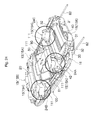
- Figs. 7 and 8 are views illustrating a speaker device adopting the above-mentioned vibration direction converter part
- Figs. 7(a) and 8(a) are cross-sectional views taken in X-axis direction
- Figs. 7(b) and 8(b) are views illustrating an operation of the driving part.
- the same symbols are applied to the same parts and a part of duplicate descriptions is eliminated.
- a link body 50L is configured to include the first connecting part 53A that is connected to the voice coil support part 40 and vibrates integrally with the voice coil support part 40 and the second connecting part 53B that is connected to the diaphragm 10 and vibrates integrally with the diaphragm 10 as well as a plurality of link parts.
- the vibration direction converter part 50 is formed with the link body 50L including the rigid first link part 51A and second link part 51B.
- the first connecting part 53A is located at one end of the first link part 51A via the hinge part 52A while the second connecting part 53B is located at another end of the first link part 51A via the hinge part 52B.
- the middle part of the first link part 51A is located at one end of the second link part 51B via the hinge part 52C while the connecting part 53C, which is static with respect to vibration of the voice coil support part 40, is located at another end of the second link part 51B via the hinge part 52D.
- the first connecting part 53A is connected to the end of the voice coil support part 40 directly or via the connecting part 60
- the second coupling part 53B is directly connected to the diaphragm 10
- the static connecting part 3C is coupled to the bottom portion 12A of the frame 12 that is the static part 100.
- a concave portion or a notch part 73 which acts as a contact avoiding part 70, is formed at the bottom portion 12A of the frame 12 that is an attaching counterpart 200 arranged near the hinge part 52D, such that a space is formed between the hinge part 52D and the bottom portion 12A of the frame 12.
- the notch part is formed.
- the first link part 51A and the second link part 51B are obliquely disposed in different directions with respect to the vibration direction (X-axis direction) of the voice coil support part 40 and the static part 100 is provided on the opposite side of the diaphragm 10 with respect to the vibration direction converter part 50.
- the static part 100 is formed with the bottom portion 12A of the frame 12
- a yoke 22A of a magnetic circuit 20 may be the static part 100 instead of the bottom portion 12A of the frame 12 by extending the yoke 22A of the magnetic circuit 20 to the position under the vibration direction converter part 50.
- the hinge part 52A on the side of the voice coil support part 40 moves in the X-axis direction in accordance with the movement of the voice coil support part 40 while the hinge part 52D connected to the static part 100 is fixed.
- the movement of the hinge part 52A is converted to the change in the angles of the first link part 51A and the second link part 51B, and thus the hinge part 52B on the side of the diaphragm 10 is moved in the vibration direction of the diaphragm 10 (for example, Z-axis direction).
- the speaker device 1B shown in Fig. 8 is configured with the driving parts 14 shown in Fig. 7 symmetrically disposed opposite to each other, which includes the driving parts 14(R) and 14(L), respectively.
- Each of the driving parts 14(R) and 14(L) includes a link body 50L(R) or 50L(L), a voice coil support part 40(R) or 40(L), a magnetic circuit 20(R) or 20(L) and a connecting part 60(R) or 60(L).
- the link bodies 50L(R) and 50L(L) configure the vibration direction converter part 50 such that a pair of the first link parts 51A, a pair of the second link parts 51B, a pair of the first connecting parts 53A, the second connecting part 53B and the static connecting part 53C, which are disposed opposite to each other, are integrally formed.
- a pair of the first connecting parts 53A are connected to the voice coil support part 40 respectively
- the second connecting part 53B is connected to the diaphragm 10
- the static connecting part 53C is connected to the bottom portion 12A of the frame 12.
- the diaphragm 10 may be driven by two combined driving forces of the driving parts 14(R) and 14(L) by setting the vibration directions of the voice coil support part 40(R) and 40(L) synchronously opposite to each other. Further, since a plurality of hinge parts 52B are provided on the side of the diaphragm 10, the number of support points on the diaphragm 10 is increased, thereby the phase of vibration of the diaphragm 10 may become uniform.
- Figs. 9 and 10 are views illustrating more specific vibration direction converter part ( Fig. 9(a) is a perspective view, Fig. 9(b) is an enlarged view of part A in Fig. 9(a) , Fig. 10(a) is a plan view illustrating a flattened whole part by unfolding the vibration direction converter part and Fig. 10(b) is a side view illustrating a flattened whole part by unfolding the vibration direction converter part.
- the vibration direction converter part 50 is formed with a single integrated component.
- the vibration direction converter part 50 is formed with a pair of the first link parts 51A, hinge parts 52A and 52B formed at both ends of the first link parts 51A, a pair of the second link parts 51B and hinge parts 52C and 52D formed at both ends of the second link parts 51B.
- the first connecting parts 53A are formed at one ends of a pair of the first link parts 51A via the hinge parts 52A
- the second connecting part 53B is formed between hinge parts 52B formed at other ends of a pair of the first link parts 51A
- the static connecting part 53C is formed between the hinge parts 52D formed at other ends of the second link parts 51B.
- the first link parts 51A, 51A and the second connecting part 53B are bent in a convex shape and the second link parts 51B, 51B and the static connecting part 53C are bent in a concave shape.
- the hinge part 52A is bendably formed with the above continuous member 50P.
- the above rigid member 50Q is attached to the first link part 51A and also to the first connecting part 53A.
- the first connecting part 53A is joined by the above rigid member 50Q.
- all of the above-mentioned hinge parts are formed in the similar configuration.
- slant faces 51t and 53t are formed opposite to each other in each hinge part.
- the vibration direction converter part 50 including the link parts 51A, 51B, each hinge part and the connecting part 53A, 53B, 53C, is formed with an integral sheet-shaped member.
- the hinge parts 52A are formed linearly crossing the integral sheet-shaped member, while the hinge parts 52B, 52C, 52D are formed partially crossing the integral sheet-shaped member.
- a pair of notch parts 50S are formed in a longitudinal direction of the integral sheet-shaped member such that the second link parts 51B, 51B and the static coupling part 53C are cut out and formed.
- the vibration direction converter part 50 is formed, for example, by applying resin material forming the rigid member 50Q to the whole surface of the continuous member 50P that is a sheet-shaped member, such that the resin material is laminated on the continuous member 50P, and cutting in a V-shape to form each hinge part and the slant faces 51t and 53t at both sides thereof. After that, the above-mentioned notch part 50S is formed and the resin material is hardened. A liquid unhardened resin material or resin film may be used as the resin material used in this embodiment.
- each hinge part and the slant faces 51t and 53t at both sides thereof may be formed at the same time as forming the rigid member 50Q with the resin material. It is preferable that a cross-sectional V-shape groove or a concave portion is formed preliminarily in a die, which is used to mold the rigid member 50Q.
- Figs. 11 , 12 and 13 are views illustrating other examples of the vibration direction converter part 50 ( FIG. 11(a) is a side view, Fig. 11(b) is a perspective view, Fig. 12 is a view illustrating an operation and Figs. 13(a) and 13(b) are views illustrating formation examples).
- the vibration direction converter part 50 (link body 50L) includes a pair of driving parts.
- the vibration direction converter parts 50 are substantially symmetrically disposed opposite to each other and a parallel link is formed with a plurality of link parts.
- the vibration direction converter part 50 includes a pair of first link parts 51A(R) and 51A(L) having a hinge part 52A(R) and 52A(L) to a first connecting part 53A (R) and 53A (L) at one end, and having a hinge part 52B(R) and 52B(L) to a second connecting part 53B at another end. Also, the vibration direction converter part 50 includes a pair of second link parts 51B(R) and 51B(L) having hinge parts 52C(R) and 52C(L) to the middle parts of the first link parts 51A(R) and 51A(L) at one end, and having hinge parts 52D(R) and 52D(L) to the static connecting part 53C at another end.
- the first connecting part 53A is connected to the voice coil 30 or the voice coil support part 40 directly or via the connecting part 60 as other member, while the second connecting part 53B is connected to the diaphragm 10 and the static connecting part 53C is connected to the bottom portion 12A of the frame 12 that is the static part 100, the yoke 22, etc. forming the magnetic circuit 20.
- vibration direction converter part 50 includes a pair of third link parts 51C(R) and 51C(L) having hinge parts 52E(R) and 52E(L) at one end to a pair of the connecting parts 53D(R) and 53D(L) integrally extending from the first connecting part 53A (R) and 53A (L), and having hinge parts 52F (R) and 52F (L) at another end to a connecting part 53E that is integral with the second connecting part 53B.
- first link part 51A(R) and the third link part 51C(R), the first link part 51A(L) and the third link part 51C(L), the second link part 51B(R) and the third link part 51C(L), and the second link part 51B(L) and the third link part 51C(R) form parallel links respectively.
- This link body 50L of the vibration direction converter part 50 substantially includes a function combining the link body of the embodiment shown in Fig. 7 and the parallel link body.
- Each link part and connecting part are formed by integrating the continuous member 50P with the rigid member 50Q, while each hinge part between link parts is linearly formed with the bendable continuous member 50P, and thus link parts are mutually integrally formed via hinge parts.
- the second connecting part 53B arranged near the hinge parts 52F (R) and 52F (L) and a pair of the connecting part 53D(R) and 53D(L) arranged near the hinge parts 52A(R) and 52A(L) form concave portions 76 as the contact avoiding part 70, such that a space is formed between each hinge part and connecting part.
- the static connecting part 53C functions as the static part 100.
- the vibration direction converter part 50 when the hinge parts 52A(R) and 52A(L) is moved from the reference position X0 to X1 in the X-axis direction in accordance with vibration of the voice coil support part 40, the second connecting part 53B and the connecting part 53E integrally with the second connecting part 53B moving up keeping a parallel state by the parallel link body, while the first link parts 51A(R) and 51A(L) and the third link parts 51C(R) and 51C(L), which configure a parallel link, are angle-varied as they are erected.
- hinge parts 52D(R) and 52D(L) are supported at both ends of the static connecting part 53C as the static part, they receive a reaction force from the static part and angle of the first link parts 51A(R) and 51A(L) and the third link parts 51C(R) and 51C(L) is securely varied and the displacement of the hinge parts 52A(R) and 52A(L) from the position X0 to X1 is securely converted to the displacement of the diaphragm 10 from the position Z0 to Z1.
- hinge parts 52D(R) and 52D(L) are supported by the static part, they receives a reaction force from the static part and angle variation of the first link parts 51A(R) and 51A(L) and the third link parts 51C(R) and 51C(L) is securely produced and the displacement of the hinge parts 52A(R) and 52A(L) from the position X0 to X2 is securely converted to the displacement of the diaphragm 10 from the position Z0 to Z2.
- the vibration in the X-axis direction of one voice coil support part 40 is converted to the vibrations in the Z-axis direction of the hinge parts 52B(R) and 52B(L), 52F (R) and 52F (L), and the second connecting part 53B, which vibrate substantially in the same phase and the same amplitude.
- the vibration of the voice coil support part 40 may be transmitted substantially in the same phase to the planar diaphragm 10 with large area.
- a pair of the connecting parts 53B, 53D(R) and 53D(L) and the third link parts 51C(R) and 51C(L) are disposed in a width direction and parallel respectively.
- the first link parts 51A(R) and 51A(L) are formed in a biforked shape, and the hinge parts 52C(R) and 52C(L) to the second link parts 51B(R) and 51B(L) are formed at the middle parts of the first link parts 51A(R) and 51A(L).
- the second link parts 51B(R) and 51B(L) and the connecting part 53C are placed between a pair of the connecting parts 53B, 53D(R) and 53D(L) and the third link parts 51C(R) and 51C(L), which are disposed in a width direction and parallel.
- the diaphragm 10 can be vibrated and supported by a face, and thereby the whole diaphragm 10 can be vibrated substantially in the same phase and divided vibration may be restrained.
- the first link parts 51A(R) and 51A(L), and the second connecting parts 53B are configured by folding the whole single sheet-shape component forming the link parts in a convex-trapezoid shape, while the second link parts 51B(R) and 51B(L), and the static connecting part 53C are configured by folding a partially taken-out portion of this plate component.
- this vibration direction converter part 50 is formed by joining a plurality of sheet-shape components 501, 502 (for example, two components) as shown in Fig. 13(a) .
- the first connecting parts 53A(R) and 53A(L), the first link parts 51A(R) and 51A(L), the second link parts 51B(R) and 51B(L), the second connecting parts 53B and the static connecting part 53C are formed in one sheet-shape component 501, while the connecting parts 53D, the third link parts 51C(R) and 51C(L) and the connecting parts 53E are formed in another sheet-shape component 502.
- the third link parts 51C(R) and 51C(L) and the connecting parts 53D(R) and 53D(L) are formed along the first link parts 51A(R) and 51A(L) and the second connecting parts 53B, and an opening 502A is formed in the sheet-shape component 502 corresponding to the second link parts 51B(R) and 51B(L) and the static connecting part 53C.
- the opening 502A formed in another sheet-shape component 502 corresponding to the second link parts 51B(R) and 51B(L) and the static connecting part 53C of one sheet-shape component 501, is formed so as to expand inward from ends of another sheet-shape component 502.
- This configuration may prevent the second link parts 51B(R) and 51B(L), and the static connecting part 53C from contacting another sheet-shape component 502, and thus a smooth movement of the link body may be performed.
- the continuous members 50P, 50P are integrated, and thereby hinge parts 52 may smoothly bend.
- the concave portion or the notch part 76 is formed as the contact avoiding part 70 near the hinge part 52.
- the slant face as shown in Fig. 5(c) is formed at the end of each link part near each hinge part.
- the slant face is formed such that the link parts do not interfere with each other when they bend at the hinge parts.
- the link parts can efficiently bend at the hinge parts.
- the above-mentioned sheet-shape component 501 and the sheet-shape component 502 are integrally formed with the sheet-shape component 502 connected to the end of the sheet-shape component 501 as shown in Fig. 13(c) .
- the vibration direction converter parts 50 shown in Figs. 11 and 12 may be obtained by folding the integrated components along a folding line f in the direction of an arrow.
- the vibration direction converter part 50 may be simply configured by applying resin material forming the rigid member 50Q to the whole surface of the continuous member 50P that is a sheet-shaped member, cutting in a V-shape to form each hinge part and the slant faces at both sides thereof, and then forming the above-mentioned notch part 50S and opening 502A and hardening the resin material in the same way as shown in Fig. 10 .
- the rigid member 50Q may be formed with the resin material and molded at the same time. It is preferable that a cross-sectional V-shape groove or a concave portion is preliminarily formed in a die, which is used to mold the rigid member 50Q.
- the link body of the vibration direction converter part 50 may be configured with a single integral component with respect to two opposing voice coil support parts 40, the assembly operation may be simplified as well when configuring a speaker device provided with a pair of driving parts.
- the hinge parts 52D(R) and 52D(L) may be held at fixed positions even if they are not particularly supported by the frame 12 corresponding to opposing vibrations of the voice coil support parts 40 (a plurality of the voice coil support parts 40 vibrate in directions opposite to each other), and thus the vibration direction converter part may be simply built into a speaker device.
- the second connecting parts 53B fixed to the diaphragm 10 may be stably moved in parallel in the Z-axis direction corresponding to the opposing vibrations of the voice coil supporting parts 40. Accordingly, it is possible to apply stable vibrations to the planar diaphragm 10.
- the voice coil support part 40 vibrates along the magnetic gap 20G formed in a direction different from the vibration direction admissible for the diaphragm 10, and this vibration is direction-converted by the vibration direction converter part 50 and transmitted to the diaphragm 10, and thereby vibrating the diaphragm 10 to emit a sound in the sound emission direction SD corresponding to the audio signal SS.
- the direction of the magnetic gap 20G is configured to cross the vibration direction of the diaphragm 10 and the thickness direction of the speaker device 1, 1A, 1B, increasing the driving force of the magnetic circuit 20 or the vibration of the voice coil 30 does not directly affect the size of the speaker device 1, 1A, 1B in the thickness direction (Z-axis direction). Accordingly, it is possible to make the speaker device 1, 1A, 1B thin while pursuing reproduced a louder sound.
- the vibration direction converter part 50 converts the vibration direction of the voice coil support part 40 and transmits the vibration to the diaphragm 10 through the mechanical link body, transmission efficiency of vibration is high.
- the speaker device 1, 1A, 1B shown in Figs. 7 to 8 since angle variation of the first link parts 51A and the second link parts 51B is produced by the vibration of the voice coil support part 40 and reaction force of the static part 100, vibration of the voice coil support part 40 may be more securely transmitted to the diaphragm 100. Accordingly, the speaker device 1, 1A, 1 B may produce preferable reproducing efficiency.
- interval in the Z-axis direction may be provided between the position of the end 40A of the voice coil support part 40 and the position of the end 50A of the vibration direction converter part 50.
- the length (height) in the Z-axis direction (thickness) of the magnetic circuit 20 can be included in the length in the Z-axis direction of the vibration direction converter part 50, and thus the speaker device 1, 1A, 1B may be made thin while securing a sufficient length in the Z-axis direction for the magnetic circuit 20, which is required to secure a driving force.
- a necessary length of the direction converter part 50 (length of link parts 51) may be sufficiently secured even if the speaker device 1, 1A, 1B is made thin, and thus the amplitude of vibration of the diaphragm 10 may be comparatively large.
- a bottom portion 61 of the connecting part 60 is configured to slide over the bottom portion 12A of the frame 12 or the static part 100 with a predetermined distance therefrom, and thereby vibration of the voice coil support part 40 may be stabilized. Further, the end of the vibration direction converter part 50 can be linearly moved, and thus the end of the vibration direction converter part 50 connected to the diaphragm 10 can be securely and stably moved.
- the vibration direction converter part 50 shown in Fig. 14 is a modified example of the embodiment shown in Fig. 11 .
- a convex portion 510 is provided on the link part that are subject to bend by opposing vibrations of the voice coil supporting parts 40, thereby rigidity of the link part can be increased.
- the first link part 51A(R) and 51A(L), the second link parts 51B(R) and 51B(L), the connecting parts 53D(R) and 53D(L) and the connecting part 53C are provided with the convex portion 510 respectively. Further, in one example shown in Fig.
- openings 520 are provided in the link part that need no particular strength, weight of the vibration direction converter part can be decreased.
- the connecting part 53B includes the openings 520.
- the weight reduction of the vibration direction converter part is effective to broaden a reproduction characteristic or increase amplitude and a sound pressure level of a sound wave corresponding to predetermined voice currents.
- Figs. 15 to 27 are views illustrating a holding part of the speaker device according to an embodiment of the present invention.
- the holding part 15 holds the voice coil 30 at the static part and restricts the vibration of the voice coil 30 in one axis direction.
- restricting the vibration of the voice coil 30 in one axis direction by the holding part 15 means restraining the vibration of the voice coil 30 in the vibration direction of the diaphragm, and the voice coil 30 may be allowed to vibrate somewhat in the vibration direction of the diaphragm.
- the holding part 15 it is possible to prevent the voice coil 30 vibrating in the vibration direction of the diaphragm from contacting the configuring member of the magnetic circuit (plate, yoke, etc.) or the frame and restrain a trouble such as generation of an abnormal noise due to the contact.
- the holding part 15 is preferably elastically deformable in an allowable vibration direction and has rigidity in other directions.
- the voice coil 30 is supported by the voice coil support part 40, and the voice coil support part 40 is vibratably held at the static part.
- the voice coil 30 is allowed to vibrate in the X-axis direction and is restrained to vibrate in the Y axis and Z-axis directions.
- the number of the holding parts 15 is not limited to four and three or more holding parts 15 may be provided on each right and left side.
- the holding parts 15 may be preferably symmetrically provided with respect to the central axis of the voice coil 30 in the X-axis direction.
- the holding part 15 has elasticity with respect to the vibration of the voice coil 30 in the X-axis direction, and it holds the voice coil 30 in a neutral position when an electromagnetic force is not applied on the voice coil 30.
- Lead wires 31 are connected at both ends of the voice coil 30.
- Fig. 16 is a view illustrating a single holding part 15 ( Fig. 16(a) is a plan view, Fig.16 (b) is a side view and Fig. 16(c) is a cross-sectional view taken along Yi-Yi of Fig. 16(b) ).
- the holding part 15 is formed in a plate shape and includes a curved portion W, Wa.
- the holding part 15 shown here is a plate shape member with thickness t and width h. With small thickness t with respect to width h, directional property in a certain direction can be provided to allowable elastic deformation.
- the holding part 15 has smaller bending rigidity in the vibration direction of the voice coil 30 (X-axis direction) or bending around Z-axis than that in the vibration direction of the diaphragm (Z-axis direction) or bending around X-axis. More particularly, the holding part 15 is subject to deformation against a bending moment M 1 shown in Fig. 16(a) , while it is not subject to deformation against a bending moment M 2 shown in Fig. 16 (b) . Bending rigidity against the bending moment M 2 is increased with the curved portion W, Wa compared to a flat holding part 15.
- the holding part 15 includes the curved portion W as a first curved portion and the curved portion Wa as a second curved portion, which is formed continuing to the first curved portion W.
- the radius of curvature of the second curved portion Wa is smaller than the radius of curvature of the first curved portion W.
- the projection directions of the first curved portion W and the second curved portion Wa are opposite each other.
- a plurality of the curved portions W, Wa are concave and convex in the vibration direction (X-axis direction) of the voice coil 30. Therefore the holding part 15 has high compliance with respect to the vibration in the vibration direction of the voice coil 30.
- a relationship between the driving force of the voice coil 30 and the displacement of the voice coil 30 can be made linear within a practical vibration range of the voice coil 30.
- torsional rigidity of the holding part 15 may be increased. As such, generation of rolling of the voice coil 30 (vibration of the voice coil in the vibration direction of the diaphragm 10) may be restrained.
- the holding part 15 has a tabular portion F having a linear cross-sectional shape at least at its end, and the tabular portion F is formed continuing to the curved portion Wa.
- the tabular portion F is provided to fix the holding part 15 on the side of voice coil or on the side of the static part.
- the holding part 15 may be stably fixed and supported by providing with the tabular portion F that is difficult to deform and deforming mainly the curved portion W, Wa with respect to the vibration of the voice coil 30.
- Fig. 17 is a view illustrating forming examples of curved portions of the holding part 15.
- a top of the curved portion W (W1 to W4) of the holding part 15 is formed displaced with reference to the center position O in the vibration direction of the voice coil 30 (X axis-direction).
- the tops W1 and W4 are formed displaced on the side of the static part
- the tops W2 and W3 are formed displaced on the side of the voice coil.
- Figs. 17 Figs. 17 (b) and 17(c)
- the lengths from the voice coil 30 to the tops W1, W4 can be made large by displacing the top position W1 and W4 on the side of the static part with reference to the center position O, and thus the allowable range of the elastic deformation of the holding part 15 with respect to the vibration of the voice coil 30 may be widened. Therefore, the trouble may be avoided that restoration of shape of the holding part 15 is lost due to the deformation of the holding part 15 beyond a yield point when the voice coil 30 vibrates at large amplitude of the vibration.
- Fig. 18 is a view illustrating other forming examples of the curved portions of the holding part 15.
- Fig. 18(a) is a plan view
- Fig. 18(b) is a side view of an example
- Fig. 18(c) is a side view of another example.
- the width h2 of the curved portion W may be gradually increased compared to the width h 1 of the flat part F as shown in Fig. 18(b)
- the width h3 of the curved portion W may be gradually decreased compared to the width h1 of the flat part F as shown in Fig. 18(c) .
- degree of compliance of the holding part 15 may be made adjustable by adjusting the width of the curved portion W.
- Fig. 19 is a view illustrating another configuration example of the holding part 15 ( Fig. 19(a) is a plan view and Fig. 19(b) is a side view).
- the holding part 15 of this example is deformable in the vibration direction (X axis-direction) of the voice coil and has rigidity in the vibration direction (Z axis-direction) of the diaphragm, and is formed with a plurality of configuring members.
- the holding part 15 is formed by joining two configuring members 151 and 152.
- Configuring members 151 and 152 each include the curved portion W as the first curved portion and the second curved portion Wa continuously formed from the first curved portion W.
- the radius of curvature of the second curved portion Wa is formed smaller than the radius of curvature of the first curved portion W.
- the projection directions of the first curved portion W and the second curved portion Wa are opposite to each other.
- the top of the curved portion W is displaced in the side of the static part with reference to the center position O in the vibration direction of the voice coil 30 (X axis-direction), and include a tabular portion F with linear cross-sectional shape at least at the end and the tabular portion F is continuously formed from the curved portion Wa.
- the plurality of the configuring members 151 and 152 are arranged opposite each other, and a space surrounded by the configuring members 151 and 152 is formed between the configuring members 151 and 152. Torsional rigidity of the holding part 15 is increased by this space, and thus generation of a rolling phenomenon (vibration of the voice coil 30 in the vibration direction of the diaphragm 10) may be restrained. Further, the holding part 15 including the configuring members 151 and 152 has substantially a line-symmetrical shape. With this line-symmetrical shape of the configuring members 151 and 152, symmetry of the voice coil 30 in forward and backward vibrations may be secured.
- a balance of the voice coil 30 in forward and backward vibrations may be adjustable by making larger or smaller vibrations in one side than in the other side with reference to the neutral position.
- the holding part 15 is formed in a rectangular shape when viewed from the side surface.
- Figs. 20 , 21 and 22 are views illustrating embodiments of the unitized holding part.
- the connecting part 60 which connects the voice coil 30 or the voice coil support part 40 to the above-mentioned vibration direction converter part 50.
- An interval in the vibration direction of the above diaphragm 10 is formed between the end portion in the side of the above vibration direction converter part 50 of the voice coil 30 and the end portion in the side of the voice coil 30 of the vibration direction converter part 50.
- the connecting part 60 connects both end portions (see Fig. 7 ).
- the holding parts 15 (the first holding parts 15A) are connected to both right and left end portions of the connecting part 60, and the above-mentioned tabular portion F of the holding part 15 (15A) is connected to the connecting part 60 directly or via other member.
- the voice coil 30 or the voice coil support part 40 includes an end edge 4of extending in the direction crossing the vibration direction of the voice coil 30 in the one end portion and the other end portion of the voice coil 30 in the vibration direction, and the end edge 4of is supported by the static part via the holding part 15. More specifically, the end edge 4of is connected to the connecting part 60, and the tabular portion F in the side of one end portion of the holding part 15 is connected to both right and left end portions of the connecting part 60 and the tabular portion F in the side of the other end portion of the holding part 15 is supported to the static part.
- the speaker device includes an attachment unit 16 arranging the voice coil 30 or the voice coil support part 40 at a prescribed position with respect to the static part.
- One end portion of the holding part 15 (tabular portion F) is connected to the end edge 4of of the voice coil 30 or the voice coil support part 40 directly or via other member, while the other end portion (tabular portion F) is connected to the attachment unit 16 directly or via other member. More specifically, the tabular portion F in the side of one end of the holding part 15 is connected to the end edge 40f via the connecting part 60, and the tabular portion F in the side of the other end portion of the holding part 15 is connected to a connecting end 16f of the attachment unit 16.
- steps of attaching the voice coil 30 to the static part via the holding part 15 may be simplified.
- the holding part 15 (the second holding part 15B), holding at the static part the end edge 40f1 of the voice coil 30 or the voice coil support part 40 in the opposite side of the vibration direction converter part, includes a pair of the curved portions W, W, and is an integral part arranged in the direction that the end edge 40f1 of the voice coil 30 or the voice coil support part 40 extends. Both end portions (tabular portion F) of the second holding part 15B as the integral part are connected to the end edge 40f1 of the voice coil 30 or the voice coil support part 40, and a part of the second holding part 15B as the integral part (tabular portion F) as the integral part between a pair of the curved portions W, W is connected to the attachment unit 16.
- the second holding part 15B includes a pair of the curved portions W, W as the first curved portion W and the second curved portion Wa whose outer shape is smaller than the first curved portion W.
- the second curved portion Wa is continuously formed from the first curved portion W and the projection directions of the first curved portion W and the second curved portion Wa are opposite each other.
- a reinforcing member G is attached to the second holding part 15B as the integral part.
- the reinforcing member G is a member causing an internal loss with respect with the second holding part 15B as the integral part.
- generation of a sound wave due to vibration of the holding part may be restrained.
- generation of a sound wave due to resonance of the holding part 15 may be restrained.
- a function of damping vibration of the holding part 15 may be added.
- This reinforcing member G may be formed with a fiber member such as unwoven fabric or fabric, resin member such as rubber or polyurethane resin, or elastic member such as resin member having a foamed structure.
- the second holding part 15B as the integral part and the attachment unit 16 are connected via adhesive resin.
- the tabular portions F, F at both right and left end portions of the second holding part 15B are connected to contacting parts 40g, 40g at both right and left end portions of the end edge 40f1 via connecting parts 40g1, 40g1 having holes 40g2 respectively, and the tabular portion F in the center of the second holding part 15B is connected to the connecting end portion 16f1 of the attachment unit 16.
- the end edge 40f1 of the voice coil support part 40 in the opposite side of the vibration direction converter part of the voice coil support part 40 is formed in a concave shape with respect to the voice coil 30, and the voice coil support part 40 is formed in a planar shape restraining contact with the attachment unit 16, when the voice coil supporting part 40 is vibrated due to vibration of the voice coil 30. More specifically, in the voice coil support part 40, a comparatively large interval is formed between the connecting end portion 16f1 of the attachment unit 16 and the end edge 40f1 of the voice coil support part 40, and the voice coil support part 40 has a planar shape projecting toward the second holding part 15B as coming near the both right and left flat parts F of the second holding part 15B. Holes, in which contacting parts 40g of the right and left end portions of the other end edge 40f1 in the voice coil support part 40 are inserted, are formed in the flat parts F at both right and left end portions of the second holding part 15B.
- Fig. 22 is a view illustrating the second holding part 15B connected to the contacting part 40g.
- the second holding part 15 is connected to the voice coil support part 40 with the convex portion of the contacting part 40g fitted in or inserted into a hole 40g2 of a component 40g1 and a hole FO of the tabular portion F.
- Fig. 23 is a view illustrating a specific formation example of the holding part 15 formed by joining the configuring members 151 and 152.
- Fig. 23 (a) is a perspective view showing a separate configuring member 151 or 152
- Fig. 23(b) is a side view of the holding part 15
- Fig. 23(c) is a plan view thereof.
- Fig. 23(d) is a modified example thereof.
- the configuring member 151 (152) of the holding part 15 are contacted with each other at their tabular portions F, including the first curved portion W and the second curved portion Wa, and the tabular portions F, F at both end portions, including connecting faces F1 and F2 orthogonal to the tabular portion F.
- a plurality of the configuring members 151 and 152 are metal members and joined by welding. According to an example shown in the drawing, the configuring members 151 and 152 are welded by applying a spot welding to the tabular portions F, F while facing each other. In this example, spot weldings are applied to a plurality of spots at each of tabular portions F, F of both end portions (symbols s show spots of spot welding).
- spot weldings are applied to a plurality of spots at each of tabular portions F, F of both end portions (symbols s show spots of spot welding).
- an elastic member M such as adhesive resin, silicone-system resin, etc. may be provided near the face where the two configuring members 151 and 152 constructing the holding part 15 are combined, in order to cause an internal loss.
- the holding part 15 for example, substantially in a symmetrical shape, while the two configuring members 151 and 152 having substantially the same shape are disposed opposite each other, performance of the holding part 15 (stiffness symmetry during the vibration stroke) may be improved.
- "stiffness symmetry during the vibration stroke” means symmetry of the stiffness curve when a voice coil moves in one direction and the stiffness curve when the voice coil moves in another direction.
- Fig. 24 is a perspective view illustrating an example of supplying a voice coil with a signal via the holding part 15.
- a holding part 15 made of a metal material having conductivity is used for a plurality of the configuring members 151 and 152, and this holding part 15 is a part of wiring.
- the voice coil 30 and the voice coil support part 40 are attached to the static part 100 via the attachment unit 16.
- a pair of the voice coil 30 or the voice coil support part 40 are connected to the vibration direction converter part 50 via the connecting part 60.
- the first holding part 15A has one end portion connected to the connecting part 60, and an other end portion supported by the attachment unit 16.
- the second holding part 15B has both end portions connected to both right and left end portions of the voice coil 30 or the voice coil support part 40, and the central part connected to the attachment unit 16.
- Fig. 25 is a partial enlarged view of Fig. 24 .
- Fig. 25(a) is an enlarged view of part 24A of Fig. 24
- Fig. 25(b) is an enlarged view of part 24B of Fig. 24 .
- Part 24C in Fig. 24 is symmetrical to part 24A in Fig. 24 , and thus its enlarged view is not shown.
- Fig. 25(a) shows in detail that one connecting face F2 of the first holding part 15A is connected to a connect terminal part 42 of a voice coil lead wire 32 (conducting layer).
- Fig. 25(b) shows in detail that another connecting face F1 of the first holding part 15A is connected to a terminal part 81.
- the first holding part 15A has a connecting face F1 in the side of one end portion connected to the terminal part 81, and a connecting face F2 in the side of another end portion connected to the connect terminal part 42 of the voice coil lead wire 32.
- the terminal part 81 connects a pair of the first holding part 15A in the side of one end electrically to a wiring 82 (external), and an audio signal inputted from the wiring 82 is supplied to a voice coil lead wire 32 via the terminal part 81 and the first holding part 15A.
- the terminal part 81 is a conducting member formed in a rod shape.
- the terminal part 81 has a positioning hole.
- the terminal part 81 is positioned at a specified location of the static part 100 with this positioning hole inserted by a positioning projection 111 provided at the static part 100. Further, a part of the terminal part 81 is insulated, and a surface of conducting member in a region where connecting with the connecting face F1 of the first holding part 15A is exposed so as to be electrically connectable to the first holding part 15A. Further, the terminal part 81 may be electrically connected to the connecting face F 1 of the holding part 15 by constructing the terminal part 81 with an insulating member such as resin member, etc. and providing a conducting member on this insulating member.
- one configuring member may be made of a rigid material and another configuring member may be made of a material causing an internal loss.
- resin material such as rubber, polyurethane resin, etc. or a resin member having a foamed structure, are included.
- the second holding part 15B to which the above-mentioned reinforcing member G is attached is included. Further, not limited to the above embodiment, the second holding part 15B may be connected to the attachment unit 16, sandwiching another configuring member causing an internal loss between the second holding part 15B and the attachment unit 16.
- a resin member such as rubber with a metal member arranged inside may be used as a plurality of configuring members of the holding part 15, or different metal members may be used as the plurality of configuring members.
- internal loss may preferably be generated since a metal member is covered with a resin member.
- generation of resonance may be restrained at a joining face where a plurality of metal members are joined.
- an elastic member such as adhesive resin, silicone-system resin, etc. may be provided near the face where the two configuring members 151 and 152 constructing the holding part 15 are joined, in order to cause internal loss. More specifically, an elastic member such as adhesive resin, silicone-system resin, etc. may be provided in a space formed between the second curved portions Wa opposite each other of the holding part 15.
- Fig. 26 shows a modified example of a holding structure of the holding part.
- a holding structure that a damper so-called butterfly damper supports the voice coil 30 at the static part is shown.
- the damper is formed in a tabular shape principally using an elastically deformable resin member or metal member.
- the holding structure shown in the drawing includes an annular shape part 150 surrounding the voice coil 30, and the inner periphery part of the holding part 15 is connected to the voice coil 30 directly or via other member (voice coil support part 40, annular shape part 151), and the outer periphery part of the holding part 15 is connected to the static part 100 via the annular shape part 150.
- voice coil support part 40, annular shape part 151 voice coil support part 40, annular shape part 151
- the outer periphery of the voice coil 30 or the voice coil support part 40 is supported by the annular shape part 151.
- the annular shape part 151 is made of so-called damper members, which are made of, for example, unwoven fabric or fabric made of synthetic fiber, etc. or fiber members of unwoven fabric or fabric impregnated with adhesive resin such as phenol resin, an elastically deformable resin member, rubber or metalmember. Further, the annular shape part 151 is preferably formed to have rigidity (including bending rigidity) in the vibration direction of the diaphragm 10 as necessary. Further, a wiring 82 is arranged along the holding part 15.
- Fig. 27 shows a modified example of the holding part.
- the holding part 15 is a damper including a rigid member holding the voice coil 30 at a prescribed height with respect to the static part 100.
- the rigid member may be constructed with a resin member.
- the damper is constructed with a fiber member and adhesive resin applied to the surface or inside of the fiber member, providing the fiber member with rigidity.
- the damper includes a single curved portion, it may include a plurality of curved portions.
- the holding part 15 may be formed with a plurality of metal members, for example, two plate shaped metal members with a curved cross-section as a rigid member.
- any dampers shown in the drawings are formed with a plurality of the configuring members 151 and 152.
- One configuring member 151 includes at least a first curved portion Wa1.
- Another configuring member 152 includes a first curved portion Wa2, a second curved portion Wa3 and a third curved portion Wa4.
- the configuring members 151 and 152 are joined at substantially the same height.
- the inner periphery part of the configuring member 152 is located on the opposite side of projected curved portion of the configuring member 152 with respect to the outer periphery part of the configuring member 152 compared to the example shown in Fig. 27 (a) .
- the inner periphery part of the configuring member 152 sis located in the side of projected curved portion of the configuring member 152 with respect to the outer periphery part of the configuring member 152 compared to the example shown in Fig. 27 (a) .
- performance of damper may be adjustable by changing the vertical position of the inner periphery part of the configuring member 152.
- "stiffness symmetry during the vibration stroke” means symmetry of the stiffness curve when a voice coil vibrates in one direction and the stiffness curve when the voice coil vibrates in another direction.
- the "stiffness symmetry during the vibration stroke" is improved when the position of the inner periphery part of the configuring member 152 is elevated on the condition that the configuring member 152 is connected above the configuring member 151 and the configuring member 152 is projected upward. If the position of the inner periphery part of the configuring member 152 is lowered, stiffness asymmetry of vertical vibration (asymmetry between the stiffness curve when a voice coil vibrates in one direction and the stiffness curve when the voice coil vibrates in another direction) becomes large.
- one configuring member 151 is arranged in the side of the vibration direction converter part 50 and the other configuring member 152 is arranged in the side of the voice coil 30
- one configuring member 151 may be arranged in the side of the voice coil 30 and the other configuring member 152 may be arranged in the side of the vibration direction converter part 50 as necessary.
- Figs. 28 to 31 are views illustrating the speaker device 1T according to an embodiment of the present invention
- Fig. 28 is a plan view
- Fig. 29 is a cross-sectional view taken along line X-X
- Fig. 30 is a rear view
- Fig. 31 is a perspective view without a first frame.
- the same symbols are applied to the same parts and duplicated explanations are eliminated.
- the example shown in Figs. 11 and 12 are adopted as the vibration direction converter part 50.
- the diaphragm 10 is formed in a rectangular shape viewed from the sound emission direction, and a curved portion 10A with ellipticalouter shape and concave cross-sectional shape is formed near the central part, and thus the diaphragm 10 has a predetermined bending rigidity in the vibration direction of the diaphragm 10 and the vibration direction of the voice coil 30. Further, with the concave shaped curved portion 10A formed at the diaphragm 10, density of the curved portion 10A becomes larger than other part of the diaphragm 10 and thereby rigidity may be made comparatively large. Further, when a pair of the vibration direction converter parts 50 are arranged opposite each other, the curved portion 10A is formed between a pair of the hinge parts 52B which are formed between the vibration direction converter part 50 and the diaphragm 10.
- the diaphragm 10 Since the diaphragm 10 has rigidity (bending rigidity included) in the vibration direction of the diaphragm, generation of deflection, etc. of the diaphragm 10 may be restrained, and thus generation of difference in phase between sound waves, deterioration of acoustic characteristic, etc. may be restrained. Further, with the curved portion 10A of the diaphragm 10 formed between a pair of the hinges 52B that is formed between the vibration direction converter part 50 and the diaphragm 10, generation of deflection may be restrained.
- the diaphragm 10 is formed substantially in a rectangular shape including a short axis extending in the vibration direction of the voice coil 30 and a long axis extending along the direction orthogonal to the vibration direction of the voice coil 30, a reinforcing part (not shown) may be formed in the direction of the long axis or the short axis.
- the reinforcing part includes a groove part, having, for example, V-shaped cross-section, which is formed linearly, annularly or in a lattice shape in the front face or rear face of the diaphragm 10.
- filling material such as damping material may be applied to inside of the groove part.
- rigidity (bending rigidity included) of the diaphragm 10 may be increased and the peak and dip of sound pressure frequency characteristic of a speaker may be lowered.
- fiber member made of unwoven fabrics (not shown), etc. may be applied instead of forming the groove part.
- rigidity (bending rigidity) of the diaphragm 10 may be increased, and thus generation of deformation such as deflection in the diaphragm 10 due to vibration or air resistance transmitted from the vibration direction converter part when the diaphragm 10 vibrates, may be restrained. Further, provided with the reinforcing part, an internal loss of the diaphragm 10 may be improved.
- the diaphragm 10 is formed with a first layer constructed with foamed resin including acrylic resin, etc. and a second layer including a fiber member such as a glass fiber, configuring a stacking structure in which the first layer is sandwiched between a pair of the second layers.
- a forming material of the diaphragm 10 for example, resin material, metal material, paper material, fiber material, ceramics material, compound material, etc. may be adopted.
- elastic member functioning as a packing including resin member), adhesive resin, etc. are included.
- the edge 11 vibratably supports the diaphragm 10 in the vibration direction (Z-axis direction), and restrains vibration in the direction orthogonal to the vibration direction (Y-axis direction).
- the edge 11 is formed in a ring shape (annular shape) viewed from the sound emission direction, and the cross-section of the edge 11 is formed in a prescribed shape, for example, a concave shape, convex shape, corrugated shape, etc. in the sound emission direction.
- a ring shape annular shape
- the cross-section of the edge 11 is formed in a prescribed shape, for example, a concave shape, convex shape, corrugated shape, etc. in the sound emission direction.
- a filler-applied member with a material such as fur, cloth, rubber or resin, rubber member or resin member molded in a prescribed shape
- a projection part projecting from the front face (in the sound emission direction), or from the rear face (in the direction opposite to the sound emission direction) or a concave portion may be formed, rigidity of the edge 11 in a prescribed direction may be increased.
- the static part 100 is divided into a first frame 12B (a first configuring member 100A) and a second frame 12C (a second configuring member 100B), and the diaphragm 10 is supported around an opening part at the center of the first frame 12B via the edge 11.
- the magnetic circuit 20 has a structure, which can be divided into two parts sandwiching the voice coil 30, one part arranged above and the other part arranged below the voice coil 30.
- the upper one part is supported by the first frame 12B and the lower other part is supported by the second frame 12C.
- an upper yoke 22B with respect to the first frame 12B and a lower yoke 22A with respect to the second frame 12C are supported substantially in parallel respectively.
- the static part 100 includes an outer peripheral frame part 101 surrounding the diaphragm 10 and a bridge part 102 bridging inside of the outer peripheral frame part 101.
- the bridge part 102 exerts a reaction force on the above link body 50L (vibration direction converter part 50), and has rigidity in the vibration direction of the link body 50L.
- the vibration is transmitted to the diaphragm 10 via the link body 50L.
- the link body 50L angle converting the link part 51 is subjected to a reaction force exerted by the diaphragm 10.
- the link body 50L is subjected to this reaction force, if the static part 100 supporting the link body 50L is deflected, the link body 50L itself vibrates, and thus the link body 50L may transmit unwanted vibration to the link part 51.
- the unwanted vibration transmitted to the link part 51 is transmitted to the diaphragm 10, the vibration of the voice coil 30 may not be efficiently transmitted to the diaphragm 10.
- the bridge part 102 which is a part of the static part 100 supporting the link body 50L, is provided with a function of restraining generation of deflection, and thus unwanted vibration that may be transmitted to the link part and the diaphragm 10 may be restrained. As such, vibration of the voice coil 30 may be efficiently transmitted to the diaphragm 10.
- compliance of the bridge part 102 is preferably substantially the same or smaller than compliance of the outer peripheral frame part 101 in the vibration direction of the diaphragm 10. More specifically, thickness of the bridge part 102 is preferably substantially the same or larger than thickness in a part of the static part 100 supporting the diaphragm 10 or the magnetic circuit 20.
- the bridge part 102 provided at the second frame 12C has a first projection part 102A projecting in the direction that the bridge part entends and in the vibration direction of the diaphragm 10.
- This first projection part 102A includes a rib structure formed in a longitudinal direction of the bridge part 102, which increases bending rigidity of the bridge part 102.
- a second projection part 102B is formed extending in the direction crossing the first projection part 102A, in the plane of the bridge part 102 facing the diaphragm 10.
- This second projection part 102B acts as a reinforcing rib at both end portions of the bridge part 102, and rigiditly supports the bridge part 102 at the outer peripheral frame part 101 by both end portions.
- the bridge part 102 has a third projecting part 102C crossing the first projection part 102A and the second projecting part 102B.
- the third projecting part 102C is formed in the plane of the static part 100 facing the diaphragm 10, and a reinforcing part 103 having polygonal planar shape is formed with a plurality of the second projection part 102B and the third projecting part 102C.
- the first frame 12B includes the outer peripheral frame part 101 of the static part 100 as a first outer peripheral frame part 101A, and includes a second outer peripheral frame part 101B supporting the diaphragm 10 inside the first outer peripheral frame part 101A.
- An opening inside the second outer peripheral frame part 101B is sealed by the edge 11 and the diaphragm 10.
- a projection part 101B1 projecting in the sound emission direction is formed at the second outer peripheral frame part 101B by which the diaphragm 10 is supported via the edge 11. With this projection part 101B1, rigidity to support the circumpherence of the diaphragm 10 is obtained.
- the first frame 12B and the second frame 12C configuring the static part 100 are formed in a planar shape having a long axis and a short axis, and the bridge part 102 is formed in the short axis direction. Further, the bridge part 102 may be formed in the long axis direction or in the long and short axis directions, and thus rigidity of the static part 100 may be obtained.
- Convex portions 100m are formed at the four corners of the first frame 12B, and concave portions 100n are formed at the four corners of the second frame 12C.
- the convex portions 100m and the concave portions 100n are fitted such that the first frame 12B and the second frame 12C are coupled.
- the convex portion 100m may be formed at one of the first frame 12B and the second frame 12C, and the concave portion 100n may be formed at the other one of the first frame 12B and the second frame 12C.
- the concave portion 100n may be formed to be a hole.
- the vibration direction converter part 50 includes a first link part 51A and a second link part 51B as the link body 50L, and one end of the second link part 51B is supported by the first link part 51A and the other end is supported by the bridge part 102.
- the bridge part 102 supporting the second link part 51B is formed in a tabular shape, and a connecting part 104, where the other end of the second link part 51B and the bridge part 102 are connected, forms a single plane.
- a projection part 104A is formed at the connecting part 104 of the bridge part 102, and a hole 104B in which the projection part 104A is inserted, is formed at the connecting part 53C integrally formed at the end of the second link part 51B via the hinge part 52.
- the projection part 104A of the connecting part 104 in the bridge part 102 acts as a positioning part positioning the vibration direction converter part 50 with respect to the static part 100.
- the vibration direction converter part 50 is positioned with respect to the static part 100, with the projection part 104A inserted into the hole 104B at the connecting part 53C, which is integrally formed at the end of the second link part 51B via the hinge part 52.
- the second connecting part 53B of the vibration direction converter part 50 is connected to the rear side of the diaphragm 10 supported by the first frame 12B, and the static connecting part 53C of the vibration direction converter part 50 is connected to the connecting part 104 formed at the central part of the bridge part 102 in the second frame 12C.
- the second connecting part 53B is a part integrally formed at the end of the first link part 51A via the hinge part 52B, and the end of the first link part 51A and the diaphragm10 is connected with this second connecting part 53B connected to the diaphragm 10.
- a concave portion is formed at the face of the diaphragm 10 in the sound emission side facing the second connecting part 538, and the diaphragm 10 has rigidity.
- the static connecting part 53C is a part integrally formed at the end of the second link part 51B via a hinge part 52D, and the hole 104B is formed at the connecting part 53C.
- the projection part 104 is inserted into the hole 104B, and thereby the connecting part 104 and the end portion of the second link part 51B are connected.
- the voice coil support part 40 supporting the voice coil 30 has one end portion at which the connecting part 60 is attached in the vibration direction of the voice coil supporting part 40, and the connecting part 60 is attached such that the connecting part 60 extends along the width of the voice coil support part 40.
- the connecting part 60 includes a connecting step part 60S to which the first connecting part 53A of the vibration direction converter part 50 is detachably connected, and a through hole 60p passing through in the vibration direction of the voice coil support part 40.
- the through-hole 60p is a vent hole formed to reduce air resistance exerted to the connecting part 60 upon vibration of the voice coil support part 40.
- This connecting part 60 connects the first connecting part 53A of the vibration direction converter part 50 and the end portion of the voice coil support part 40 with an interval, which allows the height of the magnetic circuit 20 to fall within the range of the height of the vibration direction converter part 50.
- the holding part 15 includes the first holding part 15A and the second holding part 15B, having curved plate member which allow a deformation in one direction in the vibration direction of the voice coil support part 40 and restrict deformations in other directions.
- the first holding part 15A and the second holding part 15B hold the voice coil support part 40 at the first frame 12B and the second frame 12C via the attachment unit 16.
- the first holding part 15A holds the connecting part 60 at one side part of the attachment unit 16, and the inner end portions of the first holding part 15A in the right side and left side are connected to both outer end portions of the connecting part 60, and each of outer ends of the first holding part 15A is connected to the attachment unit 16.
- the first holding part 15A is formed with a conducting metal and electrically connected to a lead wire 31 extending from the end portion of the voice coil 30 via the voice coil lead wire 32 (conducting layer 43), and an audio signal is supplied to the voice coil 30 via the first holding part 15A. Further, the first holding part 15A is electrically connected to linear terminal parts 81, 81 supported by the frame 12, and is electrically connected to outside via wirings 82, 82 electrically connected to these terminal parts 81, 81.
- the second holding part 15B has the central part connected to other side part of the attachment unit 16 and both end portions connected to the right and left end portions of the voice coil support part 40.
- the second holding part 15B is arranged within the width of the voice coil support part 40 such that a holding body of the voice coil support part 40 does not take up space in the width direction of the voice coil support part 40.
- the second holding part 15B which is formed with a continuous member, has a continuous shape at the central part, it may be formed by a plurality of members.
- a part of the second holding part 15B is arranged projecting outside the static part 100, a part of the second holding part 15B may be modified so as to fit into the static part 100.
- the terminal parts 81, 81 may be stably fixed to the static part 100, and thereby a bad connection to the voice coils 30, 30 may be avoided. Further, the terminal parts 81, 81 are formed to have a long axis extending from one voice coil 30 to another voice coil 30 and a short axis crossing the long axis. With the long and thin shape as above, efficiency of the installation space may be improved.
- the terminal parts 81, 81 include connecting parts 81a connected to wirings 82, 82 (second wiring), which are electrically connected to outside and the terminal parts 81, 81 are electrically connected at the connecting part 81a.
- the wirings 82 are fixed to the side face of the static part 100 and connected to the terminal parts 81, 81.
- the outer peripheral frame part 101 of the static part 100 includes a side face to which a wiring 82 is attached, and guiding parts 106, 106 guiding the wire 82 are formed at the side face of the static part 100.
- the voice coil lead wire 32 (conducting layer 43), connected to the lead wire 31 extending from the end portion of the voice coil 30, is formed on the voice coil support part 40 (base) supporting the voice coil 30.
- the conducting layer 43 is pattern-formed on the voice coil support part 40 (base) surrounding the conducting member of the voice coil 30, and this conducting layer 43 electrically connects the conducting member of the voice coil 30 and the holding part15.
- a wiring, electrically connecting the voice coil 30 and the terminal parts 81, is formed at the holding part 15 and the end portions of the terminal parts 81, 81 and the wiring are electrically connected.
- the wiring of the holding part 15 and the voice coil lead wire are connected, and the terminal parts 81, 81 and the wire 82 are connected, and thereby an external audio signal is inputted to the voice coil 30.
- a connecting part F1 connected to the terminal parts 81, 81, is formed at the holding part 15.
- This connecting part F1 extends in the direction crossing the vibration direction of the diaphragm 10 (X-axis direction), and is formed in a tabular shape so as to contact with the terminal parts 81, 81.
- the connecting part F2 extends in the direction crossing the vibration direction (Z-axis direction) of the diaphragm 10 and is formed in a tabular shape so as to contact with the end portion of the voice coil lead wire 32.
- the attachment unit 16 includes an integral support part 16c integrally supporting a first connecting part 16a and a second connecting part 16b, the first connecting parts 16a, to which the end portion of the first holding part 15A is connected, are provided at both right and left sides of the connecting part 60, and the second connecting part 16b, to which the second holding part 15B is connected, is formed at the back of the voice coil support part 40. Further, connecting holes 16d, opposite to the convex portions 100m provided at the first frame 12B of the static part 100, are provided at the four corners of the attachment unit 16.
- the voice coil support part 40, the connecting part 60, the holding part 15 and the attachment unit 16 are unitized and fixed between the first frame 12B and the second frame 12C.
- the first connecting parts 53A (R), 53A(L) of the direction converter part 50 shown in Figs. 11 and 12 are attached to the connecting step part 60s of the connecting part 60 such that the vibration direction converter part 50 and those already unitized, including the voice coil support part 40, the connecting part 60, the holding part 15 (the first holding part 15A and the second holding part 15B) and the attachment unit 16, are integrated.
- the upper yoke part 22B and the lower yoke part 22A of the magnetic circuit 20 are arranged above and below these parts (voice coil support part 40 included) respectively and sandwiched by the first frame 12B and the second frame 12C of the static part 100.
- the static connecting part 53C of the vibration direction converter part 50 is fitted in and immovably supported by a support table 12D formed at the bottom portion 12A of the second frame 12C and other parts such as the attachment unit 16 are also positioned at predetermined locations with respect to the first fame 12B and the second frame 12C. Further with the convex portions 100m provided at the first frame 12B of the static part 100 inserted into the connecting holes 16d provided at the four corners of the attachment unit 16, the attachment unit 16 may be fixed at a predetermined position with respect to the static part 100.
- the upper yoke 22B of the magnetic circuit 20 is first mounted to the inner face of the first frame 12B, and then the attachment unit 16, the vibration direction converter part 50, etc. are mounted thereto, and thus positioned respectively.
- the second frame 12C is stacked so as to sandwich each component between the first frame 12B and the second frame 12C while the lower yoke 22A of the magnetic circuit 20 is mounted thereto.
- the second connecting part 53B of the vibration direction converter part 50 and the diaphragm 10 are joined with adhesive as a joining member, while the outer periphery part of the diaphragm 10 is attached to the second outer peripheral fame part 101B of the first frame 12B via the edge 11.
- a groove part is circumferenctially formed at the bottom portion of the second outer peripheral frame part 101B near the outer periphery part of the edge 11.
- the groove part is formed as a joining member reception part receiving protrusion of adhesive as a joining member joining the edge 11 and the first frame 12B.
- a projection part projecting toward the frame 12B at the outer periphery of the edge 11 is formed and inserted into the groove, and thus a joining strength of the edge 11 and the first frame 12B may be strengthened.
- assembling processes may be constructed as follows:
- the frame12 as the static part 100 includes the first frame 12B (the first configuring member) and the second frame 12C (the second configuring member) as described above, and the first frame 12B is arranged in the sound emission side of the speaker device 1T, while the second frame 12C is arranged in the opposite side (rear side) of the sound emission side.
- the driving part 14 of the speaker device1 is supported so as to be sandwiched between the first frame 12B and the second frame 12C.
- the annularly formed outer peripheral frame part 101 of the first frame 12B supports one side (22B) of the magnetic pole members (yoke part) 22
- the second frame 12C includes the outer peripheral frame part 101 and the bridge part 102 and supports the other side (22A) of the magnetic pole member (yoke part) 22of the magnetic circuit 20.
- the first frame 12B and the second frame 12C include a concave receiving part 105 receiving a part of the yoke part 22.
- a projecting part 22p is fitted into this receiving part 105 and the yoke part 22 is positioned to form a proper magnetic gap.
- an opening 101S is formed between the bridge part 102 and the outer peripheral frame part 101 of the second frame 12C.
- the fourth projecting part (not shown) is formed along the outer periphery of the opening 101S of the outer peripheral frame part 101.
- the fourth projection part increases torsional rigidity of the outer peripheral frame part 101.
- an excessive-vibration restraining part 108 is formed at the first frame 12B to restrain an excessive vibration of the voice coil 30.
- the excessive-vibration restraining part 108 projects into a movable region of the voice coil 30, and an excessive vibration of the voice coil 30 is restrained with the excessive-vibration restraining part 108 contacted with the voice coil support part 40.
- a notch part 41f is formed at the base of the voice coil support part 40, and the projection part of the excessive-vibration restraining part 108 is arranged in the notch part 41f (see Fig. 22 ).
- the magnetic circuit 20 is attached to the first frame 12B and the second frame 12C with the magnetic pole member 22 joined to the magnet.
- the magnetic pole member 22 has a plurality of projection parts 22p and the projection parts 22p are supported by the receiving part 105.
- a width of the plate shaped yoke part 22 is decreased from the vibration direction converter part 50 to the static part 100, and thus the holding part 15 is prevented from contacting the yoke part 22.
- the magnetic circuit 20 has the yokes 22A and 22B attached to the first frame 12B and the second frame 12C, and an interval as the magnetic gap 20G is provided between the yokes 22A and 22B or the magnetic 21 by connecting the first frame 12B and the second frame 12C.
- the height of the magnetic circuit 20 is substantially the total height of the whole device, and the voice coil support part 40 is configured to vibrate near the center of the magnetic circuit 20, while the end portion of the voice coil support part 40 and the end portion of the vibration direction converter part 50 are connected at different heights via the connecting part 60.
- each link part of the vibration direction converter part 50 can secure a sufficient length within the height of the device, and a part of the height of the magnetic circuit 20 can be falled within the height of the vibration direction converter part 50.
- the speaker device can be made thin and can make louder sound.
- a thin speaker device capable of emitting louder reproduced sound with a comparatively simple structure can be realized by vibrating the diaphragm in a direction different from the vibration direction of the voice coil.
- durability of the hinge part of the link body that can tolerate the high-speed vibration specific to a speaker device and flexibility that can restrain generation of abnormal sound during high-speed vibration, may be required.
- the hinge part of the link body can have the durability and flexibility.
- a speaker device which is light weight and easy to manufacture, can be realized.
- Fig. 32 is a view illustrating an electronic device including a speaker device according to an embodiment of the present invention.
- an electronic device 2 such as a mobile phone or a handheld terminal shown in Fig. 32(a) or an electronic device 3 such as a flat panel display shown in Fig. 32(b)
- a speaker device is housed in the housing, which act as the attaching counterpart provided at the electronic device 3.
- the speaker device is attached to the side face of the housing as the attaching counterpart of the electronic device. Even if this case, since installation space in thickness direction required for installing the speaker device 1 may be decreased, the whole electronic device may be made thin. Further, a sufficient audio output may be produced even by the electronic device made thin.
- Fig. 33 is a view illustrating an automobile provided with a speaker according to an embodiment of the present invention.
- in-car space may be widened with the speaker device 1 made thin.
- the speaker device 1 according to the embodiment of the present invention even if attached to a door panel, ceiling, rear tray or a dashboard as the attaching counterpart, may comparatively reduce a bulge projecting into a door panel, ceiling, and thus enabling to widen space for a driver to operate or space inside room. Further, with sufficiently produced audio output, it is possible to enjoy listening to music or radio broadcasting pleasantly in a car even when driving on a noisy highway.
- a hotel, an inn or a training facility as a building including a speaker device when the speaker device 1 is provided on a wall or ceiling as the attaching counterpart, installation space in thickness direction required for the speaker device 1 may be reduced and thus enabling to save space in a room and make effective use of space.
- the hotel is capable of holding an event and accommodating many guests for conference, meeting, lecture, party, etc. Further, providing a room equipped with audiovisual equipment can be seen in recent years along with prevalence of a projector or a big-screen TV.
- a living room, etc. used as a theater room without room equipped with audiovisual equipment. Also in this case, the living room, etc. can be easily converted to a theater room with the speaker device 1 while making effective use of space in the living room.
- the placement at which the speaker device 1 is arranged may be, for example, ceiling or wall, etc. (attaching counterpart).
Applications Claiming Priority (1)
| Application Number | Priority Date | Filing Date | Title |
|---|---|---|---|
| PCT/JP2009/062479 WO2011004477A1 (ja) | 2009-07-09 | 2009-07-09 | スピーカ装置 |
Publications (1)
| Publication Number | Publication Date |
|---|---|
| EP2453673A1 true EP2453673A1 (de) | 2012-05-16 |
Family
ID=43428916
Family Applications (1)
| Application Number | Title | Priority Date | Filing Date |
|---|---|---|---|
| EP09847080A Withdrawn EP2453673A1 (de) | 2009-07-09 | 2009-07-09 | Lautsprechervorrichtung |
Country Status (5)
| Country | Link |
|---|---|
| US (1) | US20110158462A1 (de) |
| EP (1) | EP2453673A1 (de) |
| JP (1) | JPWO2011004477A1 (de) |
| CN (1) | CN102474689A (de) |
| WO (1) | WO2011004477A1 (de) |
Families Citing this family (13)
| Publication number | Priority date | Publication date | Assignee | Title |
|---|---|---|---|---|
| WO2010046988A1 (ja) * | 2008-10-23 | 2010-04-29 | パイオニア株式会社 | スピーカ装置 |
| WO2010097930A1 (ja) * | 2009-02-26 | 2010-09-02 | パイオニア株式会社 | スピーカ装置用ボイスコイル、スピーカ装置 |
| US8290198B2 (en) * | 2009-03-19 | 2012-10-16 | Pioneer Corporation | Speaker device |
| US20120114136A1 (en) * | 2009-07-09 | 2012-05-10 | Tohoku Pioneer Corporation | Speaker device |
| CN102132585A (zh) * | 2009-07-09 | 2011-07-20 | 日本先锋公司 | 扬声器装置 |
| US20110176703A1 (en) * | 2009-07-29 | 2011-07-21 | Pioneer Corporation | Speaker device |
| US20120207321A1 (en) * | 2009-10-15 | 2012-08-16 | Tohoku Pioneer Corporation | Speaker device |
| CN103987004B (zh) * | 2014-04-01 | 2017-06-27 | 国光电器股份有限公司 | 薄型扬声器 |
| JPWO2016051696A1 (ja) * | 2014-10-03 | 2017-07-13 | パナソニックIpマネジメント株式会社 | ラウドスピーカ |
| CN104598193B (zh) * | 2014-12-29 | 2020-04-24 | 联想(北京)有限公司 | 一种信息处理方法及电子设备 |
| US10499158B2 (en) * | 2015-05-19 | 2019-12-03 | Bose Corporation | Electro-acoustic transducer with radiating acoustic seal and stacked magnetic circuit assembly |
| US11184712B2 (en) | 2015-05-19 | 2021-11-23 | Bose Corporation | Dual-field single-voice-coil transducer |
| WO2022098229A1 (en) * | 2020-11-04 | 2022-05-12 | Mayht Holding B.V. | Speaker transducer |
Family Cites Families (6)
| Publication number | Priority date | Publication date | Assignee | Title |
|---|---|---|---|---|
| JPS63250995A (ja) * | 1987-04-07 | 1988-10-18 | Citizen Watch Co Ltd | 薄型スピ−カ |
| JPH08149596A (ja) | 1994-11-25 | 1996-06-07 | Matsushita Electric Ind Co Ltd | スピーカ |
| DK1627550T3 (da) * | 2003-05-09 | 2010-02-08 | Knowles Electronics Llc | Apparat og fremgangsmåde til frembringelse af akustisk energi i en modtagerindretning |
| JP3972306B2 (ja) * | 2003-11-20 | 2007-09-05 | ミネベア株式会社 | スピーカ用振動板およびこの振動板を使用したスピーカ |
| KR100533716B1 (ko) * | 2003-12-05 | 2005-12-05 | 신정열 | 수평진동 보이스코일을 구비하는 판형 스피커 |
| JP4482372B2 (ja) | 2004-05-13 | 2010-06-16 | パイオニア株式会社 | 電気音響変換器用振動板の製造方法 |
-
2009
- 2009-07-09 US US13/061,055 patent/US20110158462A1/en not_active Abandoned
- 2009-07-09 CN CN2009801603465A patent/CN102474689A/zh active Pending
- 2009-07-09 JP JP2011521743A patent/JPWO2011004477A1/ja active Pending
- 2009-07-09 WO PCT/JP2009/062479 patent/WO2011004477A1/ja active Application Filing
- 2009-07-09 EP EP09847080A patent/EP2453673A1/de not_active Withdrawn
Non-Patent Citations (1)
| Title |
|---|
| See references of WO2011004477A1 * |
Also Published As
| Publication number | Publication date |
|---|---|
| US20110158462A1 (en) | 2011-06-30 |
| WO2011004477A1 (ja) | 2011-01-13 |
| CN102474689A (zh) | 2012-05-23 |
| JPWO2011004477A1 (ja) | 2012-12-13 |
Similar Documents
| Publication | Publication Date | Title |
|---|---|---|
| EP2453673A1 (de) | Lautsprechervorrichtung | |
| EP2343910A1 (de) | Lautsprechervorrichtung | |
| US20120106772A1 (en) | Speaker device | |
| US8235167B2 (en) | Vibrating body for speaker and speaker device | |
| JP5037697B2 (ja) | スピーカ装置 | |
| US20120114136A1 (en) | Speaker device | |
| US20110200204A1 (en) | Speaker device | |
| US20120051557A1 (en) | Voice coil for speaker device, and speaker device | |
| JP5037722B2 (ja) | スピーカ装置用振動方向変換部及びスピーカ装置 | |
| WO2011004476A1 (ja) | スピーカ装置 | |
| WO2010106690A1 (ja) | スピーカ装置用磁気回路及びスピーカ装置 | |
| WO2010106674A1 (ja) | スピーカ装置 | |
| JP5037723B2 (ja) | スピーカ装置 | |
| WO2011013225A1 (ja) | スピーカ装置 | |
| WO2010106685A1 (ja) | スピーカ装置 | |
| WO2011004481A1 (ja) | スピーカ装置 | |
| WO2011013222A1 (ja) | スピーカ装置 | |
| WO2011013198A1 (ja) | スピーカ装置 | |
| JP5197768B2 (ja) | スピーカ装置 | |
| WO2010106687A1 (ja) | スピーカ装置 | |
| WO2011004480A1 (ja) | スピーカ装置用磁気回路及びスピーカ装置 | |
| WO2010106684A1 (ja) | スピーカ装置 | |
| WO2011013224A1 (ja) | スピーカ装置 | |
| JPWO2010106673A1 (ja) | スピーカ装置 |
Legal Events
| Date | Code | Title | Description |
|---|---|---|---|
| PUAI | Public reference made under article 153(3) epc to a published international application that has entered the european phase |
Free format text: ORIGINAL CODE: 0009012 |
|
| 17P | Request for examination filed |
Effective date: 20120119 |
|
| AK | Designated contracting states |
Kind code of ref document: A1 Designated state(s): AT BE BG CH CY CZ DE DK EE ES FI FR GB GR HR HU IE IS IT LI LT LU LV MC MK MT NL NO PL PT RO SE SI SK SM TR |
|
| DAX | Request for extension of the european patent (deleted) | ||
| STAA | Information on the status of an ep patent application or granted ep patent |
Free format text: STATUS: THE APPLICATION HAS BEEN WITHDRAWN |
|
| 18W | Application withdrawn |
Effective date: 20130515 |