EP2444293A2 - Kriechvorrichtung für ein Fahrzeug - Google Patents
Kriechvorrichtung für ein Fahrzeug Download PDFInfo
- Publication number
- EP2444293A2 EP2444293A2 EP11185830A EP11185830A EP2444293A2 EP 2444293 A2 EP2444293 A2 EP 2444293A2 EP 11185830 A EP11185830 A EP 11185830A EP 11185830 A EP11185830 A EP 11185830A EP 2444293 A2 EP2444293 A2 EP 2444293A2
- Authority
- EP
- European Patent Office
- Prior art keywords
- brake
- unit
- abnormal
- vehicle
- creep torque
- Prior art date
- Legal status (The legal status is an assumption and is not a legal conclusion. Google has not performed a legal analysis and makes no representation as to the accuracy of the status listed.)
- Granted
Links
Images


Classifications
-
- B—PERFORMING OPERATIONS; TRANSPORTING
- B60—VEHICLES IN GENERAL
- B60W—CONJOINT CONTROL OF VEHICLE SUB-UNITS OF DIFFERENT TYPE OR DIFFERENT FUNCTION; CONTROL SYSTEMS SPECIALLY ADAPTED FOR HYBRID VEHICLES; ROAD VEHICLE DRIVE CONTROL SYSTEMS FOR PURPOSES NOT RELATED TO THE CONTROL OF A PARTICULAR SUB-UNIT
- B60W30/00—Purposes of road vehicle drive control systems not related to the control of a particular sub-unit, e.g. of systems using conjoint control of vehicle sub-units
- B60W30/18—Propelling the vehicle
- B60W30/18009—Propelling the vehicle related to particular drive situations
- B60W30/18063—Creeping
-
- B—PERFORMING OPERATIONS; TRANSPORTING
- B60—VEHICLES IN GENERAL
- B60L—PROPULSION OF ELECTRICALLY-PROPELLED VEHICLES; SUPPLYING ELECTRIC POWER FOR AUXILIARY EQUIPMENT OF ELECTRICALLY-PROPELLED VEHICLES; ELECTRODYNAMIC BRAKE SYSTEMS FOR VEHICLES IN GENERAL; MAGNETIC SUSPENSION OR LEVITATION FOR VEHICLES; MONITORING OPERATING VARIABLES OF ELECTRICALLY-PROPELLED VEHICLES; ELECTRIC SAFETY DEVICES FOR ELECTRICALLY-PROPELLED VEHICLES
- B60L50/00—Electric propulsion with power supplied within the vehicle
- B60L50/10—Electric propulsion with power supplied within the vehicle using propulsion power supplied by engine-driven generators, e.g. generators driven by combustion engines
- B60L50/16—Electric propulsion with power supplied within the vehicle using propulsion power supplied by engine-driven generators, e.g. generators driven by combustion engines with provision for separate direct mechanical propulsion
-
- B—PERFORMING OPERATIONS; TRANSPORTING
- B60—VEHICLES IN GENERAL
- B60L—PROPULSION OF ELECTRICALLY-PROPELLED VEHICLES; SUPPLYING ELECTRIC POWER FOR AUXILIARY EQUIPMENT OF ELECTRICALLY-PROPELLED VEHICLES; ELECTRODYNAMIC BRAKE SYSTEMS FOR VEHICLES IN GENERAL; MAGNETIC SUSPENSION OR LEVITATION FOR VEHICLES; MONITORING OPERATING VARIABLES OF ELECTRICALLY-PROPELLED VEHICLES; ELECTRIC SAFETY DEVICES FOR ELECTRICALLY-PROPELLED VEHICLES
- B60L50/00—Electric propulsion with power supplied within the vehicle
- B60L50/50—Electric propulsion with power supplied within the vehicle using propulsion power supplied by batteries or fuel cells
- B60L50/60—Electric propulsion with power supplied within the vehicle using propulsion power supplied by batteries or fuel cells using power supplied by batteries
- B60L50/61—Electric propulsion with power supplied within the vehicle using propulsion power supplied by batteries or fuel cells using power supplied by batteries by batteries charged by engine-driven generators, e.g. series hybrid electric vehicles
-
- B—PERFORMING OPERATIONS; TRANSPORTING
- B60—VEHICLES IN GENERAL
- B60W—CONJOINT CONTROL OF VEHICLE SUB-UNITS OF DIFFERENT TYPE OR DIFFERENT FUNCTION; CONTROL SYSTEMS SPECIALLY ADAPTED FOR HYBRID VEHICLES; ROAD VEHICLE DRIVE CONTROL SYSTEMS FOR PURPOSES NOT RELATED TO THE CONTROL OF A PARTICULAR SUB-UNIT
- B60W10/00—Conjoint control of vehicle sub-units of different type or different function
- B60W10/04—Conjoint control of vehicle sub-units of different type or different function including control of propulsion units
- B60W10/08—Conjoint control of vehicle sub-units of different type or different function including control of propulsion units including control of electric propulsion units, e.g. motors or generators
-
- B—PERFORMING OPERATIONS; TRANSPORTING
- B60—VEHICLES IN GENERAL
- B60W—CONJOINT CONTROL OF VEHICLE SUB-UNITS OF DIFFERENT TYPE OR DIFFERENT FUNCTION; CONTROL SYSTEMS SPECIALLY ADAPTED FOR HYBRID VEHICLES; ROAD VEHICLE DRIVE CONTROL SYSTEMS FOR PURPOSES NOT RELATED TO THE CONTROL OF A PARTICULAR SUB-UNIT
- B60W10/00—Conjoint control of vehicle sub-units of different type or different function
- B60W10/18—Conjoint control of vehicle sub-units of different type or different function including control of braking systems
- B60W10/184—Conjoint control of vehicle sub-units of different type or different function including control of braking systems with wheel brakes
- B60W10/188—Conjoint control of vehicle sub-units of different type or different function including control of braking systems with wheel brakes hydraulic brakes
-
- B—PERFORMING OPERATIONS; TRANSPORTING
- B60—VEHICLES IN GENERAL
- B60W—CONJOINT CONTROL OF VEHICLE SUB-UNITS OF DIFFERENT TYPE OR DIFFERENT FUNCTION; CONTROL SYSTEMS SPECIALLY ADAPTED FOR HYBRID VEHICLES; ROAD VEHICLE DRIVE CONTROL SYSTEMS FOR PURPOSES NOT RELATED TO THE CONTROL OF A PARTICULAR SUB-UNIT
- B60W50/00—Details of control systems for road vehicle drive control not related to the control of a particular sub-unit, e.g. process diagnostic or vehicle driver interfaces
- B60W50/02—Ensuring safety in case of control system failures, e.g. by diagnosing, circumventing or fixing failures
- B60W50/029—Adapting to failures or work around with other constraints, e.g. circumvention by avoiding use of failed parts
-
- B—PERFORMING OPERATIONS; TRANSPORTING
- B60—VEHICLES IN GENERAL
- B60W—CONJOINT CONTROL OF VEHICLE SUB-UNITS OF DIFFERENT TYPE OR DIFFERENT FUNCTION; CONTROL SYSTEMS SPECIALLY ADAPTED FOR HYBRID VEHICLES; ROAD VEHICLE DRIVE CONTROL SYSTEMS FOR PURPOSES NOT RELATED TO THE CONTROL OF A PARTICULAR SUB-UNIT
- B60W50/00—Details of control systems for road vehicle drive control not related to the control of a particular sub-unit, e.g. process diagnostic or vehicle driver interfaces
- B60W50/02—Ensuring safety in case of control system failures, e.g. by diagnosing, circumventing or fixing failures
- B60W50/038—Limiting the input power, torque or speed
-
- B—PERFORMING OPERATIONS; TRANSPORTING
- B60—VEHICLES IN GENERAL
- B60W—CONJOINT CONTROL OF VEHICLE SUB-UNITS OF DIFFERENT TYPE OR DIFFERENT FUNCTION; CONTROL SYSTEMS SPECIALLY ADAPTED FOR HYBRID VEHICLES; ROAD VEHICLE DRIVE CONTROL SYSTEMS FOR PURPOSES NOT RELATED TO THE CONTROL OF A PARTICULAR SUB-UNIT
- B60W2510/00—Input parameters relating to a particular sub-units
- B60W2510/18—Braking system
- B60W2510/182—Brake pressure, e.g. of fluid or between pad and disc
-
- B—PERFORMING OPERATIONS; TRANSPORTING
- B60—VEHICLES IN GENERAL
- B60W—CONJOINT CONTROL OF VEHICLE SUB-UNITS OF DIFFERENT TYPE OR DIFFERENT FUNCTION; CONTROL SYSTEMS SPECIALLY ADAPTED FOR HYBRID VEHICLES; ROAD VEHICLE DRIVE CONTROL SYSTEMS FOR PURPOSES NOT RELATED TO THE CONTROL OF A PARTICULAR SUB-UNIT
- B60W2540/00—Input parameters relating to occupants
- B60W2540/12—Brake pedal position
-
- B—PERFORMING OPERATIONS; TRANSPORTING
- B60—VEHICLES IN GENERAL
- B60W—CONJOINT CONTROL OF VEHICLE SUB-UNITS OF DIFFERENT TYPE OR DIFFERENT FUNCTION; CONTROL SYSTEMS SPECIALLY ADAPTED FOR HYBRID VEHICLES; ROAD VEHICLE DRIVE CONTROL SYSTEMS FOR PURPOSES NOT RELATED TO THE CONTROL OF A PARTICULAR SUB-UNIT
- B60W2710/00—Output or target parameters relating to a particular sub-units
- B60W2710/08—Electric propulsion units
- B60W2710/083—Torque
-
- B—PERFORMING OPERATIONS; TRANSPORTING
- B60—VEHICLES IN GENERAL
- B60W—CONJOINT CONTROL OF VEHICLE SUB-UNITS OF DIFFERENT TYPE OR DIFFERENT FUNCTION; CONTROL SYSTEMS SPECIALLY ADAPTED FOR HYBRID VEHICLES; ROAD VEHICLE DRIVE CONTROL SYSTEMS FOR PURPOSES NOT RELATED TO THE CONTROL OF A PARTICULAR SUB-UNIT
- B60W2710/00—Output or target parameters relating to a particular sub-units
- B60W2710/10—Change speed gearings
- B60W2710/105—Output torque
-
- B—PERFORMING OPERATIONS; TRANSPORTING
- B60—VEHICLES IN GENERAL
- B60W—CONJOINT CONTROL OF VEHICLE SUB-UNITS OF DIFFERENT TYPE OR DIFFERENT FUNCTION; CONTROL SYSTEMS SPECIALLY ADAPTED FOR HYBRID VEHICLES; ROAD VEHICLE DRIVE CONTROL SYSTEMS FOR PURPOSES NOT RELATED TO THE CONTROL OF A PARTICULAR SUB-UNIT
- B60W2710/00—Output or target parameters relating to a particular sub-units
- B60W2710/18—Braking system
- B60W2710/182—Brake pressure, e.g. of fluid or between pad and disc
-
- Y—GENERAL TAGGING OF NEW TECHNOLOGICAL DEVELOPMENTS; GENERAL TAGGING OF CROSS-SECTIONAL TECHNOLOGIES SPANNING OVER SEVERAL SECTIONS OF THE IPC; TECHNICAL SUBJECTS COVERED BY FORMER USPC CROSS-REFERENCE ART COLLECTIONS [XRACs] AND DIGESTS
- Y02—TECHNOLOGIES OR APPLICATIONS FOR MITIGATION OR ADAPTATION AGAINST CLIMATE CHANGE
- Y02T—CLIMATE CHANGE MITIGATION TECHNOLOGIES RELATED TO TRANSPORTATION
- Y02T10/00—Road transport of goods or passengers
- Y02T10/60—Other road transportation technologies with climate change mitigation effect
- Y02T10/62—Hybrid vehicles
-
- Y—GENERAL TAGGING OF NEW TECHNOLOGICAL DEVELOPMENTS; GENERAL TAGGING OF CROSS-SECTIONAL TECHNOLOGIES SPANNING OVER SEVERAL SECTIONS OF THE IPC; TECHNICAL SUBJECTS COVERED BY FORMER USPC CROSS-REFERENCE ART COLLECTIONS [XRACs] AND DIGESTS
- Y02—TECHNOLOGIES OR APPLICATIONS FOR MITIGATION OR ADAPTATION AGAINST CLIMATE CHANGE
- Y02T—CLIMATE CHANGE MITIGATION TECHNOLOGIES RELATED TO TRANSPORTATION
- Y02T10/00—Road transport of goods or passengers
- Y02T10/60—Other road transportation technologies with climate change mitigation effect
- Y02T10/70—Energy storage systems for electromobility, e.g. batteries
-
- Y—GENERAL TAGGING OF NEW TECHNOLOGICAL DEVELOPMENTS; GENERAL TAGGING OF CROSS-SECTIONAL TECHNOLOGIES SPANNING OVER SEVERAL SECTIONS OF THE IPC; TECHNICAL SUBJECTS COVERED BY FORMER USPC CROSS-REFERENCE ART COLLECTIONS [XRACs] AND DIGESTS
- Y02—TECHNOLOGIES OR APPLICATIONS FOR MITIGATION OR ADAPTATION AGAINST CLIMATE CHANGE
- Y02T—CLIMATE CHANGE MITIGATION TECHNOLOGIES RELATED TO TRANSPORTATION
- Y02T10/00—Road transport of goods or passengers
- Y02T10/60—Other road transportation technologies with climate change mitigation effect
- Y02T10/7072—Electromobility specific charging systems or methods for batteries, ultracapacitors, supercapacitors or double-layer capacitors
-
- Y—GENERAL TAGGING OF NEW TECHNOLOGICAL DEVELOPMENTS; GENERAL TAGGING OF CROSS-SECTIONAL TECHNOLOGIES SPANNING OVER SEVERAL SECTIONS OF THE IPC; TECHNICAL SUBJECTS COVERED BY FORMER USPC CROSS-REFERENCE ART COLLECTIONS [XRACs] AND DIGESTS
- Y02—TECHNOLOGIES OR APPLICATIONS FOR MITIGATION OR ADAPTATION AGAINST CLIMATE CHANGE
- Y02T—CLIMATE CHANGE MITIGATION TECHNOLOGIES RELATED TO TRANSPORTATION
- Y02T10/00—Road transport of goods or passengers
- Y02T10/60—Other road transportation technologies with climate change mitigation effect
- Y02T10/72—Electric energy management in electromobility
Definitions
- the present invention relates to a vehicle driving force control device controlling a driving force of a vehicle.
- an engine automatic transmission vehicle (hereinafter, referred to as an engine AT vehicle)
- an accelerator pedal is not operated
- the vehicle can be slowly started (a creep phenomenon).
- an electrically-driven vehicle such as an electric vehicle or a hybrid vehicle
- the same control is performed. That is, even though the accelerator pedal is not operated, excitation current of a driving motor is controlled to control a creep torque, such that the vehicle can be slowly started.
- a negative pressure type or a positive pressure type boosting device is provided assisting a force (a stepping force) for stepping a brake pedal, and a pressure of a brake fluid (hereinafter, referred to as a brake fluid pressure) is increased by using the boosting device to increase the brake force.
- a pressure generating device supplying negative pressure or positive pressure is faulty, a pressure cannot be supplied to the boosting device.
- the brake fluid pressure is reduced as much as the assisting force by the boosting device is removed.
- the creep torque is controlled (reduced) by a value of the brake fluid pressure, it is difficult to reduce the creep torque, and as a result, a driver may feel as if a vehicle is pushed out and feel a sense of incompatibility.
- JP-2004-282903A the creep torque generated in a motor is determined according to a stroke amount of the brake pedal, but it is not distinguished whether the brake apparatus is normal or abnormal, and as a result, even when the brake force is reduced or is abnormal, the creep torque is controlled in the same manner as it is controlled when the brake apparatus is normal, such that the driver may feel as if the vehicle is pushed out and feel the sense of incompatibility.
- JP-2010-075036A when a brake is faulty, the creep torque is reduced depending on a vehicle velocity, but relevance to the brake pedal is not described and the driver may feel the sense of incompatibility.
- a vehicle driving force control device comprising: a brake unit configured to generate a brake force of a vehicle; a stroke amount detecting unit configured to detect a stroke amount of a brake pedal of the vehicle; a monitoring unit configured to monitor whether generation of the brake force of the brake unit is abnormal; and a creep torque controlling unit configured to increase a reduction amount of a creep torque of the vehicle as the stroke amount increases, when the monitoring unit determines that the generation of the brake force in the brake unit is abnormal.
- the the creep torque controlling unit may increase the reduction amount of the creep torque as the stroke amount increases in a range of a dead zone of the brake pedal.
- the brake unit may include a boosting unit that assists a stepping force for the brake pedal based on the detected stroke amount, and the monitoring unit may determine that the generation of the brake force in the brake unit is abnormal when performance of the boosting unit is abnormal.
- the brake unit may include a pressure generating unit that generates a pressure supplied to the boosting unit, and the monitoring unit may periodically drive the pressure generating unit even when the performance of the boosting unit is abnormal.
- the brake unit may generate the brake force by using a fluid pressure of a brake fluid and include a fluid pressure detecting unit that detects the fluid pressure of the brake fluid, and the monitoring unit may determine that the generation of the brake force in the brake unit is abnormal when the detected fluid pressure of the brake fluid is reduction abnormal.
- FIGS. 1 to 7 a vehicle driving force control device according to an exemplary embodiment of the present invention will be described with reference to FIGS. 1 to 7 .
- an electric vehicle is described as an example, but the present invention may be applied to a hybrid vehicle or an engine AT vehicle.
- a negative pressure type brake boosting device is described as a boosting device, but the present invention may be applied to a positive pressure type brake boosting device and a boosting device assisting a stepping force by a motor.
- a type that generates a brake force by using a pressure of a brake fluid is described as a brake unit, but the present invention may be applied to a type directly generating the brake force by the motor.
- FIG. 1 is a schematic configuration diagram showing a vehicle driving force control device according to an exemplary embodiment of the present invention
- FIG. 2 is a flowchart explaining the control in the vehicle driving force control device shown in FIG. 1
- FIGS. 3 to 5 are graphs to be used in the control shown in FIG. 2
- FIG. 3 is a graph showing the relationship between a vehicle velocity and a creep torque
- FIG. 4 is a graph showing the relationship between a stroke of a brake pedal and a reduction amount of a creep torque
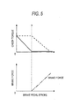
- FIG. 5 is a graph showing the relationships between the stroke of the brake pedal and the creep torque when a brake is normal and abnormal
- FIGS. 6 and 7 are flowcharts specifically explaining the monitoring whether brake force is abnormal in the control shown in FIG. 2 .
- FIG. 6 is a flowchart explaining the monitoring whether the performance of a brake boosting device is abnormal
- FIG. 7 is a flowchart explaining the monitoring whether the brake fluid pressure system is reduction abnormal.
- a vehicle 10 is an electric vehicle (EV) .
- a wheel velocity sensor 12 detecting a wheel velocity of a wheel 11 and a brake 13 (including calipers 13a and a disk 13b; a brake unit) braking the wheel 11 are installed in each wheel 11.
- a brake fluid (brake oil) is supplied from a brake fluid pipe 31 to each brake 13, and a brake fluid pressure is detected by a brake fluid pressure sensor 15 (a pressure detecting unit) installed in a calculation device 14.
- the wheel velocity sensor 12 is electrically connected to the calculation device 14 through a wiring 32, and a vehicle velocity of the vehicle 10 is calculated by a vehicle velocity calculating unit 16 installed in the calculation device 14 based on the output value detected by the wheel velocity sensor 12.
- the brake fluid is supplied to the brake 13 by stepping on a brake pedal 17.
- a stroke amount of the brake pedal 17 is detected by a brake pedal stroke sensor 21 (a stroke amount detecting unit).
- a negative pressure generating device 18 (a pressure generating unit) is connected to a brake boosting device 19 (a boosting unit) through a negative pressure pipe 34 and a negative pressure generated by the negative pressure generating device 18 is supplied to the brake boosting device 19 (the boosting unit) and the negative pressure is detected by a negative pressure sensor 22.
- a stepping force for the brake pedal 17 is assisted by the brake boosting device 19.
- a brake fluid with a pressure corresponding to a force after assisting the stepping force is supplied by a master cylinder 20 (a supplying unit).
- the brake force is generated by using the brake fluid pressure supplied from the master cylinder 20.
- the brake force of the brake 13 is controlled.
- a driving shaft 23 of the vehicle 10 is connected with a motor 26 through a differential 24, and voltage from a battery (not shown) is converted by an inverter 27 to be supplied to the motor 26, thereby driving the driving shaft 23.
- a rotation number of the motor 26 is detected by a motor rotation number sensor 25.
- a main control device 28 integrally controls the vehicle 10. And the brake fluid pressure and the wheel velocity detected and calculated by the above-described calculation device 14 are transmitted to the main control device 28 through a controller area network (CAN) bus 33 and further, the stroke amount detected by the brake pedal stroke sensor 21 and the negative pressure detected by the negative pressure sensor 22 are transmitted to the main control device 28 through the wiring 32.
- a motor torque outputted from the motor 26 is transmitted from the main control device 28 to the inverter 27 through the CAN bus 33.
- the main control device 28 includes a motor torque control unit 29 (a creep torque control unit) and a brake force generation error monitoring unit 30 (a monitoring unit) and the control of a creep torque to be described below is performed by using the units.
- step S1 It is monitored whether generation of the brake force is abnormal.
- the detailed method of monitoring whether the generation of the brake force is abnormal will be described in FIGS. 6 and 7 hereinafter.
- step S3 When the generation of the brake force is abnormal, the process proceeds to step S3, and when the generation of the brake force is not abnormal, the process proceeds to step S4 (step S2) .
- step S3 When the generation of the brake force is abnormal, the creep torque generated by the brake stroke sensor 21 is outputted (step S3).
- the EV is configured to generate the creep phenomenon like the engine AT vehicle.
- the motor 26 is controlled to generate the creep torque.
- the magnitude of the creep torque varies depending on the vehicle velocity as shown in FIG. 3 .
- the creep torque is maintained to be constant and maximum, but in a higher velocity range than the velocity range (of 0 to the low velocity), the creep torque decreases depending on the vehicle velocity, and further, in a high velocity range, the creep torque is maintained to zero.
- a reference creep torque is acquired based on the vehicle velocity of the vehicle 10 acquired by the wheel velocity sensor 12 and the vehicle velocity calculating unit 16.
- the creep torque generated by the brake stroke sensor 21 is outputted. More specifically, as shown in FIG. 4 , a reduction amount of the creep torque is acquired according to the stroke amount detected by the brake stroke sensor 21, and the creep torque reduction amount increases in proportion to the stroke amount in the range of 0 to a, and the creep torque reduction amount is maintained to be constant and maximum in a range where the stroke amount is larger than a.
- a target creep torque is acquired.
- a creep torque represented by a bold line of FIG. 5 is outputted.
- the range where the stroke amount is in the range of zero to a corresponds to a so-called allowance (a dead zone) of the brake pedal 17, and the creep torque is reduced as the stroke amount increases by actively using the range. Meanwhile, when the stroke amount is larger than a, the outputted creep torque becomes zero or a slight torque, such that the brake force increases in proportion to the stroke amount (see an alternated long and short dash line in FIG. 5 ) .
- the range where the stroke amount is in the range of zero to a is the same as the range of the dead zone of the brake pedal 17, but an offset may be provided with respect to the range of the dead zone. In this case, even through the brake force starts to increase as the stroke amount increases, the creep torque decreases for some time and thereafter, the outputted creep torque is maintained to zero or the slight torque.
- step S4 when the generation of the brake force is not abnormal, that is, when the generation of the brake force is normal, a creep torque represented by a dotted line of FIG. 5 is outputted (step S4).
- the creep torque is outputted depending on the brake fluid pressure detected by the brake fluid pressure sensor 15 of the calculation device 14.
- the range where the stroke amount is in the range of zero to a is the dead zone range, and since the brake fluid pressure does not increase, the reference creep torque acquired based on the vehicle velocity is used as represented by the dotted line of FIG. 5 .
- the brake fluid pressure increases, and as a result, the creep torque is reduced according to the increase. Consequently, the outputted creep torque is maintained to zero or the slight torque and further, the brake force increases.
- the control of the creep torque is switched depending on whether the generation of the brake force is abnormal.
- the creep torque generated by the brake stroke sensor 21 (the stroke amount) is outputted when the generation of the brake force is abnormal, and the creep torque generated by the brake fluid pressure sensor 15 (the brake fluid pressure) is outputted when the generation of the brake force is not abnormal.
- the switching of the control and the generation of the creep torque are not limited to be performed by the pedal stroke sensor but may also be performed by a stop lamp switch.
- the control is performed in the range where the stroke amount is in the range of zero to a until the brake fluid pressure increases by using the creep torque generated as above, and as a result, the creep torque can be reduced without strongly stepping the brake pedal 17, and the feeling as if the vehicle is pushed out can be eliminated.
- the brake pedal 17 is not operated, the same creep torque as that when being normal can be outputted.
- the monitoring method described below may be applied to the case where the brake boosting device is the positive pressure type as well as the case where the brake boosting device is the negative pressure type.
- the monitoring method may be applied even to the case where the brake boosting device assists the stepping force by the motor and in this case, it is monitored whether the generation of the brake force is abnormal due to a fault of the motor.
- step S11 It is monitored whether the performance of the brake boosting device 19 is abnormal or not (step S11) . Specifically, a power supply circuit thereof is monitored, a motor driving condition is monitored, or the output values of the negative pressure sensor 22 and the brake fluid pressure sensor 15 are compared with each other. For example, when the output values of the negative pressure sensor 22 and the brake fluid pressure sensor 15 are compared with each other, it is determined in the following cases that the performance is abnormal. As the compared output value, for example, output values of sensor types such as the brake stroke sensor 21 and the stop lamp switch may be used.
- step S13 When the performance of the brake boosting device 19 is abnormal, the process proceeds to step S13, and when the performance of the brake boosting device 19 is not abnormal, the process proceeds to step S17 (step S12).
- step S14 When the performance of the brake boosting device 19 is abnormal, it is checked whether the negative pressure generating device 18 is abnormal, and when the negative pressure generating device 18 is abnormal, the process proceeds to step S14, and when the negative pressure generating device 18 is not abnormal, the process proceeds to step S16 (step S13).
- the negative pressure generating device 18 When the negative pressure generating device 18 is abnormal, specifically, in the case where the negative pressure generating device 18 cannot be driven because the driving circuit and the motor are abnormal or in the case where it is determined that the performance deteriorates, the negative pressure generating device 18 stops and abnormal information is outputted (steps S14 and S15). In this case, the control of the creep torque is switched to the control when being abnormal, and as described in step S3 above, the creep torque generated by the brake stroke sensor 21 (the stroke amount) is outputted.
- the negative pressure generating device 18 is not abnormal, specifically, when it is suspected that the negative pressure sensor 22 is faulty, the negative pressure is maintained by periodically driving the negative pressure generating device 18 (step S16).
- the performance of the brake boosting device 19 is not abnormal including even the case where the negative pressure generating device 18 is not abnormal, it is not determined that the performance is abnormal, but normal information is outputted (step S17).
- the creep torque is controlled in such a manner that it is controlled when the negative pressure generating device 18 is normal and as described in step S4 above, the creep torque generated by the brake fluid pressure sensor 15 (the brake fluid pressure) is outputted.
- step S21 It is monitored whether the brake fluid pressure system is reduction abnormal or not (step S21). Specifically, the output value of the brake fluid pressure sensor 15, a power train output (the output of the motor 26), and the output value of the wheel velocity sensor 12 are compared with each other. For example, when the output value of the brake fluid pressure sensor 15 and the output value of the wheel velocity sensor 12 are compared with each other, it is determined in the following cases that the brake fluid pressure system is reduction abnormal.
- the compared output value for example, output values of sensor types such as the brake stroke sensor 21, the motor rotation number sensor 25, the stop lamp switch, and an acceleration sensor may be used.
- step S23 When the brake fluid pressure system is reduction abnormal, the process proceeds to step S23, and when the brake fluid pressure system is not reduction abnormal, the process proceeds to step S24 (step S22) .
- step S23 When the brake fluid pressure system is reduction abnormal, the abnormal information is outputted (step S23) .
- the control of the creep torque is switched to the control when being abnormal, and as described in step S3 above, the creep torque generated by the brake stroke sensor 21 (the stroke amount) is outputted.
- step S24 when the brake fluid pressure system is not reduction abnormal, the normal information is outputted (step S24).
- the creep torque is controlled in such a manner that it is controlled when the brake fluid pressure system is normal, and as described in step S4 above, the creep torque generated by the brake fluid pressure sensor 15 (the brake fluid pressure) is outputted.
- the EV is described as an example, but when a target of the creep torque controlled by the main control device 28 is changed from the motor to the engine, the present invention may be applied to the engine AT vehicle as well.
- the present invention can be applied to the hybrid vehicle or the engine AT vehicle as well and is suitable for the EV.
Landscapes
- Engineering & Computer Science (AREA)
- Transportation (AREA)
- Mechanical Engineering (AREA)
- Automation & Control Theory (AREA)
- Chemical & Material Sciences (AREA)
- Combustion & Propulsion (AREA)
- Human Computer Interaction (AREA)
- Power Engineering (AREA)
- Life Sciences & Earth Sciences (AREA)
- Sustainable Development (AREA)
- Sustainable Energy (AREA)
- Electric Propulsion And Braking For Vehicles (AREA)
- Regulating Braking Force (AREA)
- Valves And Accessory Devices For Braking Systems (AREA)
- Control Of Vehicle Engines Or Engines For Specific Uses (AREA)
Applications Claiming Priority (1)
| Application Number | Priority Date | Filing Date | Title |
|---|---|---|---|
| JP2010235213A JP5381954B2 (ja) | 2010-10-20 | 2010-10-20 | 車両駆動力制御装置 |
Publications (3)
| Publication Number | Publication Date |
|---|---|
| EP2444293A2 true EP2444293A2 (de) | 2012-04-25 |
| EP2444293A3 EP2444293A3 (de) | 2013-06-05 |
| EP2444293B1 EP2444293B1 (de) | 2017-12-13 |
Family
ID=44862600
Family Applications (1)
| Application Number | Title | Priority Date | Filing Date |
|---|---|---|---|
| EP11185830.4A Not-in-force EP2444293B1 (de) | 2010-10-20 | 2011-10-19 | Kriechvorrichtung für ein Fahrzeug |
Country Status (4)
| Country | Link |
|---|---|
| US (1) | US8956266B2 (de) |
| EP (1) | EP2444293B1 (de) |
| JP (1) | JP5381954B2 (de) |
| CN (1) | CN102452326B (de) |
Cited By (4)
| Publication number | Priority date | Publication date | Assignee | Title |
|---|---|---|---|---|
| EP2944525A4 (de) * | 2013-01-08 | 2016-01-20 | Ntn Toyo Bearing Co Ltd | Elektrische bremsvorrichtung |
| EP3184355A1 (de) * | 2015-12-22 | 2017-06-28 | Mitsubishi Jidosha Kogyo Kabushiki Kaisha | Steuerungsvorrichtung zur steuerung eines elektrofahrzeugs |
| EP3381739A4 (de) * | 2015-11-26 | 2019-05-01 | Jatco Ltd | Vorrichtung zur steuerung eines elektrofahrzeugs und steuerungsverfahren |
| WO2019162479A1 (en) * | 2018-02-26 | 2019-08-29 | Jaguar Land Rover Limited | Control system for a vehicle |
Families Citing this family (14)
| Publication number | Priority date | Publication date | Assignee | Title |
|---|---|---|---|---|
| JP2010075036A (ja) * | 2008-08-22 | 2010-04-02 | Fuji Heavy Ind Ltd | 電気自動車の制御装置 |
| JP5655635B2 (ja) * | 2011-03-01 | 2015-01-21 | 株式会社デンソー | クリープ車速制御装置 |
| KR101339239B1 (ko) * | 2011-11-29 | 2013-12-09 | 기아자동차 주식회사 | 모터를 구비한 차량의 제어방법 |
| US9308831B2 (en) * | 2012-04-27 | 2016-04-12 | GM Global Technology Operations LLC | System and method for controlling vehicle creep torque |
| US9008924B2 (en) * | 2012-05-08 | 2015-04-14 | Eaton Corporation | Transmission creep control |
| US9499154B2 (en) * | 2012-05-08 | 2016-11-22 | Eaton Corporation | Method to initiate, manage, and adapt vehicle motion at low speeds in a wet clutch dual clutch transmission |
| US9421968B2 (en) * | 2013-12-18 | 2016-08-23 | Hyundai Motor Company | System and method for controlling torque for hybrid vehicle |
| JP6186618B2 (ja) * | 2013-12-25 | 2017-08-30 | 三菱自動車工業株式会社 | 電動車両のストップランプ点灯制御装置 |
| JP6186619B2 (ja) * | 2013-12-25 | 2017-08-30 | 三菱自動車工業株式会社 | 電動車両のストップランプ点灯制御装置 |
| JP2016060443A (ja) * | 2014-09-19 | 2016-04-25 | アイシン精機株式会社 | 車両制御装置、車両制御方法、及び車両 |
| US9586570B2 (en) * | 2015-01-26 | 2017-03-07 | Siemens Industry, Inc. | Methods and system for verifying a brake system in a vehicle |
| KR102596595B1 (ko) * | 2016-10-10 | 2023-11-01 | 에이치엘만도 주식회사 | 전자식 브레이크 시스템 및 그 제어 방법 |
| CN117087632A (zh) * | 2018-12-12 | 2023-11-21 | 内蒙古北方重型汽车股份有限公司 | 电动轮矿车自动制动控制系统及其方法 |
| CN113218667B (zh) * | 2021-04-06 | 2022-06-10 | 南京航空航天大学 | 一种超磁致伸缩线控制动系统故障诊断装置及方法 |
Citations (2)
| Publication number | Priority date | Publication date | Assignee | Title |
|---|---|---|---|---|
| JP2004282903A (ja) | 2003-03-17 | 2004-10-07 | Nissan Motor Co Ltd | 車両のクリープトルク制御装置 |
| JP2010075036A (ja) | 2008-08-22 | 2010-04-02 | Fuji Heavy Ind Ltd | 電気自動車の制御装置 |
Family Cites Families (13)
| Publication number | Priority date | Publication date | Assignee | Title |
|---|---|---|---|---|
| JPS50146775A (de) * | 1974-05-18 | 1975-11-25 | ||
| JPS5455925A (en) | 1977-10-12 | 1979-05-04 | Toyoda Mach Works Ltd | Apparatus for inspecting brake system of vehicle |
| JP3348773B2 (ja) * | 1998-10-27 | 2002-11-20 | トヨタ自動車株式会社 | 車両走行制御装置 |
| JP3350815B2 (ja) | 1999-07-08 | 2002-11-25 | 本田技研工業株式会社 | 車両の駆動力制御装置 |
| JP2001165299A (ja) | 1999-12-10 | 2001-06-19 | Mitsubishi Motors Corp | 車両用自動変速機のクリープ力制御装置 |
| JP3891467B2 (ja) * | 2000-09-12 | 2007-03-14 | 本田技研工業株式会社 | ブレーキ液圧保持装置 |
| US7035727B2 (en) * | 2002-05-29 | 2006-04-25 | Visteon Global Technologies, Inc. | Apparatus and method of controlling vehicle creep control under braking |
| DE10361448A1 (de) | 2003-12-23 | 2005-08-04 | Voith Turbo Gmbh & Co. Kg | Verfahren zur Überwachung einer Bremsmomentänderung eines Retarders |
| JP2007060761A (ja) * | 2005-08-23 | 2007-03-08 | Nissan Motor Co Ltd | ハイブリッド車の減速度制御装置 |
| CN100581888C (zh) | 2007-02-25 | 2010-01-20 | 姜航波 | 汽车液压制动系统渗漏、泄漏报警保护装置及其安装方法 |
| JP5245770B2 (ja) | 2008-11-29 | 2013-07-24 | 日産自動車株式会社 | ブレーキ倍力装置、ブレーキ倍力装置付き車両、およびブレーキ倍力方法 |
| JP2010162914A (ja) * | 2009-01-13 | 2010-07-29 | Fuji Heavy Ind Ltd | バキュームポンプ制御装置 |
| JP5184406B2 (ja) * | 2009-03-11 | 2013-04-17 | 富士重工業株式会社 | 電気自動車の制御装置 |
-
2010
- 2010-10-20 JP JP2010235213A patent/JP5381954B2/ja not_active Expired - Fee Related
-
2011
- 2011-10-19 US US13/276,549 patent/US8956266B2/en not_active Expired - Fee Related
- 2011-10-19 CN CN201110318861.0A patent/CN102452326B/zh not_active Expired - Fee Related
- 2011-10-19 EP EP11185830.4A patent/EP2444293B1/de not_active Not-in-force
Patent Citations (2)
| Publication number | Priority date | Publication date | Assignee | Title |
|---|---|---|---|---|
| JP2004282903A (ja) | 2003-03-17 | 2004-10-07 | Nissan Motor Co Ltd | 車両のクリープトルク制御装置 |
| JP2010075036A (ja) | 2008-08-22 | 2010-04-02 | Fuji Heavy Ind Ltd | 電気自動車の制御装置 |
Cited By (6)
| Publication number | Priority date | Publication date | Assignee | Title |
|---|---|---|---|---|
| EP2944525A4 (de) * | 2013-01-08 | 2016-01-20 | Ntn Toyo Bearing Co Ltd | Elektrische bremsvorrichtung |
| US9840237B2 (en) | 2013-01-08 | 2017-12-12 | Ntn Corporation | Electric brake system |
| EP3381739A4 (de) * | 2015-11-26 | 2019-05-01 | Jatco Ltd | Vorrichtung zur steuerung eines elektrofahrzeugs und steuerungsverfahren |
| EP3184355A1 (de) * | 2015-12-22 | 2017-06-28 | Mitsubishi Jidosha Kogyo Kabushiki Kaisha | Steuerungsvorrichtung zur steuerung eines elektrofahrzeugs |
| WO2019162479A1 (en) * | 2018-02-26 | 2019-08-29 | Jaguar Land Rover Limited | Control system for a vehicle |
| US11794744B2 (en) | 2018-02-26 | 2023-10-24 | Jaguar Land Rover Limited | Control system for a vehicle |
Also Published As
| Publication number | Publication date |
|---|---|
| EP2444293A3 (de) | 2013-06-05 |
| EP2444293B1 (de) | 2017-12-13 |
| JP5381954B2 (ja) | 2014-01-08 |
| US20120100958A1 (en) | 2012-04-26 |
| CN102452326A (zh) | 2012-05-16 |
| JP2012090443A (ja) | 2012-05-10 |
| CN102452326B (zh) | 2015-07-22 |
| US8956266B2 (en) | 2015-02-17 |
Similar Documents
| Publication | Publication Date | Title |
|---|---|---|
| US8956266B2 (en) | Vehicle driving force control device | |
| JP5184406B2 (ja) | 電気自動車の制御装置 | |
| US9333844B2 (en) | Method and device for operating a drive device of a vehicle | |
| US6969127B2 (en) | Electric parking brake system | |
| CN102325679B (zh) | 车载用的控制装置 | |
| JP4961278B2 (ja) | 電気自動車の制御装置 | |
| CN109849933B (zh) | 确定驾驶员需求扭矩的方法、装置、车辆及可读存储介质 | |
| KR101063225B1 (ko) | 하이브리드 차량의 토크 모니터링 방법 | |
| CN105480297B (zh) | 电动转向装置 | |
| KR102664096B1 (ko) | 전기자동차의 bms 전원 단선시 제어 방법 | |
| CN107458362B (zh) | 一种真空助力制动系统的控制装置及汽车 | |
| US20130151110A1 (en) | Control apparatus for vehicle | |
| KR101304885B1 (ko) | 하이브리드 차량의 제어 방법 | |
| CN111391866B (zh) | 一种功能安全扭矩监控的方法及系统 | |
| US11870379B2 (en) | Control device for rotating electrical machine | |
| KR102819317B1 (ko) | 배터리 센서 진단 시스템 및 방법 | |
| KR101145623B1 (ko) | 하이브리드 차량의 페일 세이프 제어방법 | |
| CN102398587B (zh) | 用于对用于蓄压器的加载装置进行监测的方法和设备 | |
| JP5946293B2 (ja) | ブレーキ負圧センサの異常検出装置 | |
| JP4928977B2 (ja) | 電気負荷の制御装置及び電動ブレーキ装置 | |
| JP3264097B2 (ja) | 電気自動車の制動不良検出方法 | |
| KR20120005724A (ko) | 전기자동차 및 비상제어방법 | |
| US11695365B2 (en) | Method and device for external monitoring of a converter | |
| CN120303176A (zh) | 用于对参数进行可信性验证的方法 |
Legal Events
| Date | Code | Title | Description |
|---|---|---|---|
| 17P | Request for examination filed |
Effective date: 20111116 |
|
| AK | Designated contracting states |
Kind code of ref document: A2 Designated state(s): AL AT BE BG CH CY CZ DE DK EE ES FI FR GB GR HR HU IE IS IT LI LT LU LV MC MK MT NL NO PL PT RO RS SE SI SK SM TR |
|
| AX | Request for extension of the european patent |
Extension state: BA ME |
|
| PUAI | Public reference made under article 153(3) epc to a published international application that has entered the european phase |
Free format text: ORIGINAL CODE: 0009012 |
|
| PUAL | Search report despatched |
Free format text: ORIGINAL CODE: 0009013 |
|
| AK | Designated contracting states |
Kind code of ref document: A3 Designated state(s): AL AT BE BG CH CY CZ DE DK EE ES FI FR GB GR HR HU IE IS IT LI LT LU LV MC MK MT NL NO PL PT RO RS SE SI SK SM TR |
|
| AX | Request for extension of the european patent |
Extension state: BA ME |
|
| RIC1 | Information provided on ipc code assigned before grant |
Ipc: B60W 30/18 20120101AFI20130430BHEP Ipc: B60W 10/188 20120101ALI20130430BHEP |
|
| GRAP | Despatch of communication of intention to grant a patent |
Free format text: ORIGINAL CODE: EPIDOSNIGR1 |
|
| RIC1 | Information provided on ipc code assigned before grant |
Ipc: B60W 10/188 20120101ALI20170522BHEP Ipc: B60W 30/18 20120101AFI20170522BHEP |
|
| INTG | Intention to grant announced |
Effective date: 20170623 |
|
| GRAS | Grant fee paid |
Free format text: ORIGINAL CODE: EPIDOSNIGR3 |
|
| GRAA | (expected) grant |
Free format text: ORIGINAL CODE: 0009210 |
|
| AK | Designated contracting states |
Kind code of ref document: B1 Designated state(s): AL AT BE BG CH CY CZ DE DK EE ES FI FR GB GR HR HU IE IS IT LI LT LU LV MC MK MT NL NO PL PT RO RS SE SI SK SM TR |
|
| REG | Reference to a national code |
Ref country code: GB Ref legal event code: FG4D |
|
| REG | Reference to a national code |
Ref country code: AT Ref legal event code: REF Ref document number: 954051 Country of ref document: AT Kind code of ref document: T Effective date: 20171215 Ref country code: CH Ref legal event code: EP |
|
| REG | Reference to a national code |
Ref country code: IE Ref legal event code: FG4D |
|
| REG | Reference to a national code |
Ref country code: DE Ref legal event code: R096 Ref document number: 602011044112 Country of ref document: DE |
|
| REG | Reference to a national code |
Ref country code: NL Ref legal event code: MP Effective date: 20171213 |
|
| REG | Reference to a national code |
Ref country code: LT Ref legal event code: MG4D |
|
| PG25 | Lapsed in a contracting state [announced via postgrant information from national office to epo] |
Ref country code: LT Free format text: LAPSE BECAUSE OF FAILURE TO SUBMIT A TRANSLATION OF THE DESCRIPTION OR TO PAY THE FEE WITHIN THE PRESCRIBED TIME-LIMIT Effective date: 20171213 Ref country code: SE Free format text: LAPSE BECAUSE OF FAILURE TO SUBMIT A TRANSLATION OF THE DESCRIPTION OR TO PAY THE FEE WITHIN THE PRESCRIBED TIME-LIMIT Effective date: 20171213 Ref country code: NO Free format text: LAPSE BECAUSE OF FAILURE TO SUBMIT A TRANSLATION OF THE DESCRIPTION OR TO PAY THE FEE WITHIN THE PRESCRIBED TIME-LIMIT Effective date: 20180313 Ref country code: FI Free format text: LAPSE BECAUSE OF FAILURE TO SUBMIT A TRANSLATION OF THE DESCRIPTION OR TO PAY THE FEE WITHIN THE PRESCRIBED TIME-LIMIT Effective date: 20171213 |
|
| REG | Reference to a national code |
Ref country code: AT Ref legal event code: MK05 Ref document number: 954051 Country of ref document: AT Kind code of ref document: T Effective date: 20171213 |
|
| PG25 | Lapsed in a contracting state [announced via postgrant information from national office to epo] |
Ref country code: RS Free format text: LAPSE BECAUSE OF FAILURE TO SUBMIT A TRANSLATION OF THE DESCRIPTION OR TO PAY THE FEE WITHIN THE PRESCRIBED TIME-LIMIT Effective date: 20171213 Ref country code: BG Free format text: LAPSE BECAUSE OF FAILURE TO SUBMIT A TRANSLATION OF THE DESCRIPTION OR TO PAY THE FEE WITHIN THE PRESCRIBED TIME-LIMIT Effective date: 20180313 Ref country code: LV Free format text: LAPSE BECAUSE OF FAILURE TO SUBMIT A TRANSLATION OF THE DESCRIPTION OR TO PAY THE FEE WITHIN THE PRESCRIBED TIME-LIMIT Effective date: 20171213 Ref country code: GR Free format text: LAPSE BECAUSE OF FAILURE TO SUBMIT A TRANSLATION OF THE DESCRIPTION OR TO PAY THE FEE WITHIN THE PRESCRIBED TIME-LIMIT Effective date: 20180314 Ref country code: HR Free format text: LAPSE BECAUSE OF FAILURE TO SUBMIT A TRANSLATION OF THE DESCRIPTION OR TO PAY THE FEE WITHIN THE PRESCRIBED TIME-LIMIT Effective date: 20171213 |
|
| PG25 | Lapsed in a contracting state [announced via postgrant information from national office to epo] |
Ref country code: NL Free format text: LAPSE BECAUSE OF FAILURE TO SUBMIT A TRANSLATION OF THE DESCRIPTION OR TO PAY THE FEE WITHIN THE PRESCRIBED TIME-LIMIT Effective date: 20171213 |
|
| PG25 | Lapsed in a contracting state [announced via postgrant information from national office to epo] |
Ref country code: SK Free format text: LAPSE BECAUSE OF FAILURE TO SUBMIT A TRANSLATION OF THE DESCRIPTION OR TO PAY THE FEE WITHIN THE PRESCRIBED TIME-LIMIT Effective date: 20171213 Ref country code: CZ Free format text: LAPSE BECAUSE OF FAILURE TO SUBMIT A TRANSLATION OF THE DESCRIPTION OR TO PAY THE FEE WITHIN THE PRESCRIBED TIME-LIMIT Effective date: 20171213 Ref country code: CY Free format text: LAPSE BECAUSE OF FAILURE TO SUBMIT A TRANSLATION OF THE DESCRIPTION OR TO PAY THE FEE WITHIN THE PRESCRIBED TIME-LIMIT Effective date: 20171213 Ref country code: EE Free format text: LAPSE BECAUSE OF FAILURE TO SUBMIT A TRANSLATION OF THE DESCRIPTION OR TO PAY THE FEE WITHIN THE PRESCRIBED TIME-LIMIT Effective date: 20171213 Ref country code: ES Free format text: LAPSE BECAUSE OF FAILURE TO SUBMIT A TRANSLATION OF THE DESCRIPTION OR TO PAY THE FEE WITHIN THE PRESCRIBED TIME-LIMIT Effective date: 20171213 |
|
| PG25 | Lapsed in a contracting state [announced via postgrant information from national office to epo] |
Ref country code: SM Free format text: LAPSE BECAUSE OF FAILURE TO SUBMIT A TRANSLATION OF THE DESCRIPTION OR TO PAY THE FEE WITHIN THE PRESCRIBED TIME-LIMIT Effective date: 20171213 Ref country code: PL Free format text: LAPSE BECAUSE OF FAILURE TO SUBMIT A TRANSLATION OF THE DESCRIPTION OR TO PAY THE FEE WITHIN THE PRESCRIBED TIME-LIMIT Effective date: 20171213 Ref country code: IT Free format text: LAPSE BECAUSE OF FAILURE TO SUBMIT A TRANSLATION OF THE DESCRIPTION OR TO PAY THE FEE WITHIN THE PRESCRIBED TIME-LIMIT Effective date: 20171213 Ref country code: IS Free format text: LAPSE BECAUSE OF FAILURE TO SUBMIT A TRANSLATION OF THE DESCRIPTION OR TO PAY THE FEE WITHIN THE PRESCRIBED TIME-LIMIT Effective date: 20180413 Ref country code: RO Free format text: LAPSE BECAUSE OF FAILURE TO SUBMIT A TRANSLATION OF THE DESCRIPTION OR TO PAY THE FEE WITHIN THE PRESCRIBED TIME-LIMIT Effective date: 20171213 Ref country code: AT Free format text: LAPSE BECAUSE OF FAILURE TO SUBMIT A TRANSLATION OF THE DESCRIPTION OR TO PAY THE FEE WITHIN THE PRESCRIBED TIME-LIMIT Effective date: 20171213 |
|
| REG | Reference to a national code |
Ref country code: FR Ref legal event code: PLFP Year of fee payment: 8 |
|
| REG | Reference to a national code |
Ref country code: DE Ref legal event code: R097 Ref document number: 602011044112 Country of ref document: DE |
|
| PLBE | No opposition filed within time limit |
Free format text: ORIGINAL CODE: 0009261 |
|
| STAA | Information on the status of an ep patent application or granted ep patent |
Free format text: STATUS: NO OPPOSITION FILED WITHIN TIME LIMIT |
|
| 26N | No opposition filed |
Effective date: 20180914 |
|
| PG25 | Lapsed in a contracting state [announced via postgrant information from national office to epo] |
Ref country code: DK Free format text: LAPSE BECAUSE OF FAILURE TO SUBMIT A TRANSLATION OF THE DESCRIPTION OR TO PAY THE FEE WITHIN THE PRESCRIBED TIME-LIMIT Effective date: 20171213 |
|
| PG25 | Lapsed in a contracting state [announced via postgrant information from national office to epo] |
Ref country code: SI Free format text: LAPSE BECAUSE OF FAILURE TO SUBMIT A TRANSLATION OF THE DESCRIPTION OR TO PAY THE FEE WITHIN THE PRESCRIBED TIME-LIMIT Effective date: 20171213 |
|
| REG | Reference to a national code |
Ref country code: CH Ref legal event code: PL |
|
| GBPC | Gb: european patent ceased through non-payment of renewal fee |
Effective date: 20181019 |
|
| REG | Reference to a national code |
Ref country code: BE Ref legal event code: MM Effective date: 20181031 |
|
| PG25 | Lapsed in a contracting state [announced via postgrant information from national office to epo] |
Ref country code: LU Free format text: LAPSE BECAUSE OF NON-PAYMENT OF DUE FEES Effective date: 20181019 Ref country code: MC Free format text: LAPSE BECAUSE OF FAILURE TO SUBMIT A TRANSLATION OF THE DESCRIPTION OR TO PAY THE FEE WITHIN THE PRESCRIBED TIME-LIMIT Effective date: 20171213 |
|
| REG | Reference to a national code |
Ref country code: IE Ref legal event code: MM4A |
|
| PG25 | Lapsed in a contracting state [announced via postgrant information from national office to epo] |
Ref country code: CH Free format text: LAPSE BECAUSE OF NON-PAYMENT OF DUE FEES Effective date: 20181031 Ref country code: LI Free format text: LAPSE BECAUSE OF NON-PAYMENT OF DUE FEES Effective date: 20181031 Ref country code: BE Free format text: LAPSE BECAUSE OF NON-PAYMENT OF DUE FEES Effective date: 20181031 |
|
| PG25 | Lapsed in a contracting state [announced via postgrant information from national office to epo] |
Ref country code: GB Free format text: LAPSE BECAUSE OF NON-PAYMENT OF DUE FEES Effective date: 20181019 Ref country code: IE Free format text: LAPSE BECAUSE OF NON-PAYMENT OF DUE FEES Effective date: 20181019 |
|
| PG25 | Lapsed in a contracting state [announced via postgrant information from national office to epo] |
Ref country code: MT Free format text: LAPSE BECAUSE OF NON-PAYMENT OF DUE FEES Effective date: 20181019 |
|
| PG25 | Lapsed in a contracting state [announced via postgrant information from national office to epo] |
Ref country code: TR Free format text: LAPSE BECAUSE OF FAILURE TO SUBMIT A TRANSLATION OF THE DESCRIPTION OR TO PAY THE FEE WITHIN THE PRESCRIBED TIME-LIMIT Effective date: 20171213 |
|
| PG25 | Lapsed in a contracting state [announced via postgrant information from national office to epo] |
Ref country code: PT Free format text: LAPSE BECAUSE OF FAILURE TO SUBMIT A TRANSLATION OF THE DESCRIPTION OR TO PAY THE FEE WITHIN THE PRESCRIBED TIME-LIMIT Effective date: 20171213 |
|
| PG25 | Lapsed in a contracting state [announced via postgrant information from national office to epo] |
Ref country code: MK Free format text: LAPSE BECAUSE OF NON-PAYMENT OF DUE FEES Effective date: 20171213 Ref country code: HU Free format text: LAPSE BECAUSE OF FAILURE TO SUBMIT A TRANSLATION OF THE DESCRIPTION OR TO PAY THE FEE WITHIN THE PRESCRIBED TIME-LIMIT; INVALID AB INITIO Effective date: 20111019 |
|
| PG25 | Lapsed in a contracting state [announced via postgrant information from national office to epo] |
Ref country code: AL Free format text: LAPSE BECAUSE OF FAILURE TO SUBMIT A TRANSLATION OF THE DESCRIPTION OR TO PAY THE FEE WITHIN THE PRESCRIBED TIME-LIMIT Effective date: 20171213 |
|
| PGFP | Annual fee paid to national office [announced via postgrant information from national office to epo] |
Ref country code: FR Payment date: 20210913 Year of fee payment: 11 |
|
| PGFP | Annual fee paid to national office [announced via postgrant information from national office to epo] |
Ref country code: DE Payment date: 20210908 Year of fee payment: 11 |
|
| REG | Reference to a national code |
Ref country code: DE Ref legal event code: R119 Ref document number: 602011044112 Country of ref document: DE |
|
| PG25 | Lapsed in a contracting state [announced via postgrant information from national office to epo] |
Ref country code: FR Free format text: LAPSE BECAUSE OF NON-PAYMENT OF DUE FEES Effective date: 20221031 Ref country code: DE Free format text: LAPSE BECAUSE OF NON-PAYMENT OF DUE FEES Effective date: 20230503 |