EP2444286B1 - Support de charge pour un véhicule automobile - Google Patents
Support de charge pour un véhicule automobile Download PDFInfo
- Publication number
- EP2444286B1 EP2444286B1 EP12000178.9A EP12000178A EP2444286B1 EP 2444286 B1 EP2444286 B1 EP 2444286B1 EP 12000178 A EP12000178 A EP 12000178A EP 2444286 B1 EP2444286 B1 EP 2444286B1
- Authority
- EP
- European Patent Office
- Prior art keywords
- support
- load carrier
- loading
- assembly
- vehicle
- Prior art date
- Legal status (The legal status is an assumption and is not a legal conclusion. Google has not performed a legal analysis and makes no representation as to the accuracy of the status listed.)
- Revoked
Links
Images


Classifications
-
- B—PERFORMING OPERATIONS; TRANSPORTING
- B60—VEHICLES IN GENERAL
- B60R—VEHICLES, VEHICLE FITTINGS, OR VEHICLE PARTS, NOT OTHERWISE PROVIDED FOR
- B60R9/00—Supplementary fittings on vehicle exterior for carrying loads, e.g. luggage, sports gear or the like
- B60R9/06—Supplementary fittings on vehicle exterior for carrying loads, e.g. luggage, sports gear or the like at vehicle front or rear
-
- B—PERFORMING OPERATIONS; TRANSPORTING
- B60—VEHICLES IN GENERAL
- B60R—VEHICLES, VEHICLE FITTINGS, OR VEHICLE PARTS, NOT OTHERWISE PROVIDED FOR
- B60R9/00—Supplementary fittings on vehicle exterior for carrying loads, e.g. luggage, sports gear or the like
- B60R9/08—Supplementary fittings on vehicle exterior for carrying loads, e.g. luggage, sports gear or the like specially adapted for sports gear
- B60R9/10—Supplementary fittings on vehicle exterior for carrying loads, e.g. luggage, sports gear or the like specially adapted for sports gear for cycles
Definitions
- the invention relates to a load carrier for a motor vehicle, in particular a passenger car, having a support structure for carrying a load, which protrudes in a working position of the load carrier to the rear in front of a rear portion of the motor vehicle, according to the preamble of claim 1.
- Such a load carrier goes out, for example US Pat. No. 6,244,483 B1 out.
- Load carriers concealed in its working position, when it is arranged on the motor vehicle, a tail lamp arrangement of the passenger car. From behind the tail lights of the vehicle are thus no longer visible. Load carriers therefore have their own tail light assemblies, which are connected to the electrical system of the motor vehicle and are visible. However, arranged at an exposed point on the rear of the load carrier tail lamp assemblies are prone to damage, for example when maneuvering with the motor vehicle.
- a viewing area for a tail lamp arrangement remains free.
- At least one intermediate level can also be provided, e.g. in the manner of a staircase structure.
- the lower loading level and the upper loading level may have different loading capacities. Preferably, however, the lower and upper loading levels have substantially the same loading capacity.
- the two loading levels in the vehicle longitudinal direction are substantially the same length.
- a rear light assembly is arranged on the support structure.
- the tail light assembly is located below the upper deck level and from the rear, free end of the load carrier closer to the rear of the vehicle. It is advantageous if the upper loading level is arranged above the lower loading level in such a way that a viewing area to the rear light arrangement remains free.
- the tail lamp assembly is below the upper deck level, i. placed back to the motor vehicle, so that it is protected from damage.
- the lower and / or the upper loading level may be stationary relative to the support structure.
- a modular expansion concept in which at least one expansion component is mounted on a base carrier of the load carrier or mounted movably thereto.
- the base support forms e.g. a part of the support structure or a supporting structure movable with respect to the support structure. In this way, the loading capacity of the carrier can be increased if necessary.
- the extension member is, for example, in its position of use laterally, backwards or upwards in front of the support assembly.
- the extension member comprises one or preferably two S-shaped or S-shaped support rods.
- the S-like support rods are preferably laterally releasably attachable to the base support. Due to the S-shape, the support rods project obliquely behind at the top.
- at least one further supporting platform or at least one further sports equipment holder can be attached or attached to the at least one expansion component.
- the extension component preferably forms an actuating handle for displacing the carrying arrangement into the loading position or the driving position.
- an actuating handle e.g. a handle, be arranged on the extension member.
- the at least one extension component expediently provides the upper loading level.
- the extension member is in the use position to the rear above before, for example, the support assembly or the support structure.
- the upper loading level may for example comprise a continuous loading platform.
- a load carrier it has a respect to the support structure between a provided for a driving operation of the motor vehicle driving position and a loading and unloading of the motor vehicle provided loading position adjustable support arrangement for placing the load, wherein the support assembly with the load arranged on it releases in the loading position a swivel range of a tailgate or a rear door of the motor vehicle.
- the support structure preferably comprises a bicycle carrier, a carrier platform for placing loads or the like.
- a basic idea is to leave a support structure so to speak vehicle-fixed, for example, rearwardly projecting carrier or support arms, and to store on this support structure, the actual support assembly movable.
- the support assembly can be moved from the driving position to the loading position without having to remove the load resting on it.
- the load may remain on the support structure.
- one or the tail lamp arrangement on the support structure or the movable support arrangement, e.g. behind the lower or the upper loading level.
- the support structure expediently engages under the support arrangement, at least in the driving position.
- the support arrangement is advantageously at least in the driving position on the support structure, e.g. directly or indirectly. Indirectly e.g. on a linear guide or a pivot bearing arrangement. It is advantageous if the support arrangement is arranged at least partially above the support structure even in the loading position.
- a linear guide and / or a carriage can be provided.
- a pivot bearing arrangement with which the support assembly is pivotally mounted on the support structure. It is understood that a pivot bearing arrangement can also be linearly movable with the aid of a linear guide.
- the support assembly performs a superimposed linear and pivotal movement on an adjustment between the driving position and the loading position.
- the support assembly takes in the loading position expediently a remote from the motor vehicle skew.
- the support assembly is pivoted away in the loading position of the motor vehicle.
- the support assembly may be formed in the manner of a rocker.
- a first Wipparman extract can on the one hand define the pivot bearing the lower loading level and a second Wipparman himself the other part of the pivot bearing define the upper loading level. It is in principle also possible with a rocker-like support arrangement that the first and the second rocker arm arrangement have a reversed vertical offset or no height offset, so that they have approximately the same distance to a road surface in the driving position, for example.
- the lower and / or the upper loading level are expediently arranged on the movable support arrangement.
- the lower loading level can be provided by the support structure, while the upper loading level forms a pivotable or linearly movable loading level, which is movable relative to the lower loading level.
- a pivot axis of the pivot bearing arrangement expediently extends between a longitudinal end region of the lower loading plane facing the rear of the vehicle and a free end region of the upper loading plane facing away from the rear of the vehicle. In this way it is possible to use a free space below the upper loading level for a pivoting movement.
- the pivot axis may be horizontal obliquely and / or obliquely to the vehicle transverse direction. But is preferably an approximately horizontal course.
- the respective pivot axis can run, for example, in the region of the lower loading level. But even in the area between the two lower and upper loading levels or at the upper loading level, a pivot axis may be provided.
- the respective pivot axis extends approximately in the region of a longitudinal center between the lower and the upper loading level.
- the support assembly is expediently substantially balanced with and without load. It is understood that here also a unique tilt position can be advantageous, i. that the support assembly pivots about the pivot axis in the loading position or the release position automatically and remains there. At least in the other position, the support assembly is then advantageously held by a locking or holding device.
- the pivot axis expediently passes through a pivot bearing or a pivot bearing pair of the pivot bearing arrangement or is defined by this pivot bearing. Preferably then only a single pivot axis is present.
- pivoting the support assembly with respect to the support structure a plurality of pivot axes are present. But there are also one or more spatially remote from the pivot bearing assembly pivot axes possible. This at least one pivot axis may be fixed in space or movable in space, ie not be room-solid.
- the pivot bearing assembly comprises e.g. a multi-joint arrangement.
- a multi-joint arrangement For example, two spaced apart in the vehicle transverse direction of multi-joints are provided for pivoting the support assembly with respect to the support structure.
- Particularly preferred is a four-bar arrangement or a four-bar linkage. It is also possible to provide more or less than 4 joints.
- the four-bar linkage can be designed such that the carrying arrangement assumes a substantially horizontal position both in the driving position and in the loading position.
- the multi-joint arrangement comprises a swivel arm remote from the rear area and a steering arm arranged closer to the rear area, the steering arm being longer than the swivel arm.
- the support assembly has expediently at least in the loaded state such a center of gravity position that it automatically remains in the driving position and / or in the loading position.
- the support structure thus remains here without an additional support or support in the respective driving position or loading position.
- the support assembly passes between the driving position and the loading position an adjustment with a tipping point. The support assembly tilts then, so to speak, in the driving position or the loading position.
- brackets or the like are advantageous for holding in the driving position and / or in the loading position. These can also be provided as an additional security measure.
- the tail lamp assembly can be arranged to be pivotable or otherwise movable on the load carrier, for example, on the support structure.
- a movable, in particular pivotable tail lamp arrangement can release, for example, a pivoting path for pivoting the support assembly.
- a support arrangement which is movable relative to a support structure of a load carrier has a lower first and an upper, second, plane remote from the rear of the vehicle.
- a basic idea is that the upper loading level is further away from the road surface than the lower loading level, so that below the upper loading level below the carrying arrangement, a larger range of movement, in particular pivoting, remains free.
- a tail lamp assembly may, but need not be, disposed on the support structure. It could for example also be arranged on the support arrangement.
- a foot control device for actuating the support assembly.
- actuation forces available.
- the foot actuator acts e.g. on the support structure with respect to the movably mounted support structure.
- the foot control device with the support assembly is fixed or hinged or slides along the support assembly to the actuation along.
- the foot control device e.g. a linear guide and / or pivot bearing arrangement for the movable mounting of the support assembly with respect to the support structure acts.
- the foot operating device may act on a pivot arm of the pivot bearing arrangement, in particular the multi-joint arrangement or a single pivot bearing.
- the foot control device is e.g. connected to a swivel arm fixed or hinged or is formed by a pivoting arm.
- the foot control device has expediently a clearance, so that it is adjustable between a rest position in which it is out of engagement with the support assembly, and a working position in which it is for adjusting the support assembly with this engaged.
- a locking device for locking the support assembly with respect to the support structure is provided at least in the driving position. Unintentional pivoting or linear movement of the support structure, which could be dangerous when driving, is prevented by the locking device.
- the load carrier in particular the movable support arrangement, may for example comprise a carrier platform for parking the load and / or a sports equipment holder.
- the sports equipment holder is for example a bicycle holder. It is understood that sports equipment holders are expediently releasably connectable to the support assembly components.
- the support structure contains e.g. a displaceably arranged on the motor vehicle carrier part.
- the displaceable support part is a carrier part, which can be pulled out to the rear on the body of the vehicle, a pivoting part or the like. It is particularly preferred if the carrier part forms a kind of drawer.
- the support structure expediently comprises at least two support elements or support rods spaced from one another in the vehicle transverse direction.
- These support elements can be plugged into receptacles, for example, through a bumper of the motor vehicle, for example.
- the recordings are connected to longitudinal members of a body of the motor vehicle.
- the support structure has a holder for releasably arranging on a trailer coupling of the motor vehicle.
- load carriers 10a, 10b, 10c and 10d identical components are provided with the same reference numerals.
- load carrier 10a specific components are marked with “a”
- load carrier 10b, 10c and 10d specific components with “b”, “c” and "d”.
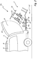
- the load carrier 10a is arranged at a rear region 11 of a motor vehicle 12.
- a support structure 13a with two longitudinal members 14a, 14b is fixed to the vehicle 12 connected to the vehicle.
- the side members 14a, 14b are inserted in schematically illustrated receptacles 57 on the body 15 from the rear.
- the support structure 13a may also be provided with a hitch bracket 16 to a ball neck 17 of a trailer hitch 18 of the motor vehicle 12 releasably secured.
- the side rails 14a, 14b and the hitch bracket 16 are connected by one or more cross members 54.
- a support assembly 19a is movably mounted with a support frame 20 between a driving position F and a loading position L.
- the carrying arrangement 19a In the loading position L, the carrying arrangement 19a is pivoted away at an angle with respect to the motor vehicle 12, so that it releases a pivoting region 21 of a tailgate 22.
- the tailgate 22 may pivot past bicycles 23 which are mounted on the support assembly 19a with sports equipment holders 24.
- the bicycles 23 are a load 34 placed on the carrying arrangement 19a.
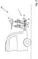
- a pivot bearing arrangement 25 is provided between these two components.
- the pivot bearing arrangement 25 comprises two multi-joint arrangements 26a, 26b, which in the present case are configured as four-jointed joints 27a, 27b.
- the four joints 27a, 27b include pivot arms 28 and steering arms 29, which are pivotally mounted on pivot bearings 30, 31 on the longitudinal beams 14a, 14b.
- the pivot bearings 30, 31 are located at a longitudinal end of the arms 28, 29.
- At a longitudinal end opposite this longitudinal end are further pivot bearings 32, 33 between the arms 28 and 29 on the one hand and the support assembly 19 a on the other hand present.
- the support assembly would when pivoting from the driving position F in the loading position L and vice versa a parallelogram-like movement go through, ie their top would always be horizontal or at least substantially horizontal.
- the pivot arms 28 are shorter than the steering arms 29. This pivots the support assembly 19a, so that it is in the loading position L obliquely away from the rear of the vehicle 12. This measure increases the pivoting range 21.
- foot-operated devices 35a, 35b are expedient.
- the foot actuator 35a includes, for example, a pedal 36 that is operatively connected to one of the shorter pivot arms 28.
- the pedal 36 is rotatably and pivotally connected to the pivot arm 28.
- a one-piece construction, in which the pivot arm 28 is extended so to speak to the pedal 36, is conceivable.
- the pedal 36 is angled in front of the pivot arm 28. By a simple foot operation of the pedal 36, the support assembly 19a can be pivoted into the loading position L.
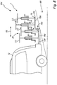
- His foot control device 35b includes, for example, an actuating part 37 which extends in the vehicle transverse direction of the motor vehicle 12.
- the operating member 37 is pivotally mounted on the support structure 13a.
- the actuating member 37 engages two spaced engagement points on the support assembly or the pivot bearing assembly.
- the actuating member 37 comprises a pivoting bracket 38 with arms 39, between which a pivoting bracket 38 with e.g. a foot 60 operable actuating rod 40 extends.
- the actuating rod 40 is welded, for example, to the arms 39 at one longitudinal end thereof.
- swivel bracket 38 formed from a plurality of components, an integral swivel bracket could also be provided.
- the arms 39 are pivotally mounted on the support structure 13a.
- a separate pivot bearing may be provided on the support structure for a pivotal mounting of an actuating part according to the invention.
- the arms 39 are pivotally mounted on the pivot bearing 30.
- the actuating rod 40 is pivotally mounted on the pivot bearings 30 relative to the pivot arms 28.
- a clearance 41 is present, in which the swivel bracket 38 between a rest position R, at the operating ends 42 of the arms 39 out of engagement with the pivot arms 28, and a working position A is adjustable, in which the operating ends 42 engage the pivot arms 28.
- actuation recesses 43 are provided on the actuation ends 42 for this purpose.
- the foot-operated device 35b has such a center of gravity position that it remains autonomously in the rest position R.
- the foot control device 35b is pivoted in its rest position R, for example, upwards.
- the foot actuator 35b then needs e.g. less space.
- the actuating rod 40 is in its rest position R on the two side rails 14a, 14b at positions 56a, 56b.
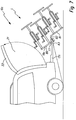
- the load carriers 10a, 10b have a flexible extension concept.
- the support frame 20 includes a base support 44, the provided by a support platform 53 load capacity can be increased by extension members 45.
- the extension members 45 are, for example, support rods 46 projecting rearwardly in front of the base support 44.
- support platform 53 In front of the support platform 53 are also provided as extension components supporting elements 58, e.g. for parking the bicycles 23.
- the support elements 58 are expediently telescopic and / or displaceable with respect to the base support 44, so that they can be pushed under the support platform 53 when not in use.
- the support rods 46 have a stepped or S-like course. Fastening portions 47 of the support rods 46, which have a substantially horizontal course in the driving position F, are fastened to support elements 48 of the support frame 20 extending in the vehicle longitudinal direction. Thus, the attachment portions 47 extend corresponding to the support members 48.
- the attachment portions 47 may be attached laterally to the support members 48, for example. For securing, for example, securing splines, bolts or the like may be provided.
- the attachment portions 47 may also Be L-shaped or U-shaped so that they can be saddled so to speak on the support members 48 and supported on the support members 48 at least on the upper side.
- Adjacent to the attachment portions 47 are inclined portions 49 of the support rods 46.
- the inclined sections 49 extend inclined in the driving position F obliquely away from the motor vehicle 12. At the inclined portions 49 close to support portions 50 of the support rods 46, which extend in the driving position F is substantially horizontal.
- a support platform or load supports e.g. Sports Equipment Holder 24, be attached.
- the supporting sections 50 or sports equipment holders 24 arranged thereon preferably form actuating handles for adjusting the carrier arrangement 19a from the driving position F to the loading position L and / or vice versa.
- the support sections 50 and / or the sports equipment holder 24 collar relatively large with respect to the pivot bearing 30 and thus form actuating arms or operating lever, which allow easy manual operation of the support assembly 19a in an adjustment of the driving position F in the loading position L and vice versa.
- the operability of the load carrier 10b is thus not limited, even if, for example, the foot operating part 37 is less accessible through the extension with the aid of the extension components 45.
- the support arrangement 19a can be locked with a locking device 51 with respect to the support structure 13a.
- the locking device 51 includes, for example, a but firmly connected to the support assembly 19a, but movable locking member 52, such as a locking screw or a locking bolt which engages for locking in a locking receptacle 55 of the support structure 19a.
- the support assembly 19a provides with the attached by extension members 45, a lower loading level 65 and an upper loading level 66 ready.
- a free space 67 for pivoting the carrying arrangement 19a in the direction of a road surface 69.
- the upper loading level 66 leaves a viewing area to a tail lamp assembly 70, which is arranged at the free end of the support structure 13 facing away from the motor vehicle 12.
- the tail lamp assembly 70 includes taillights 71 which are connectable to a vehicle electrical system 72, for example via a connection 73, in which a plug of the load carrier 10a is plugged into a socket of the motor vehicle 12.
- a stepped support arrangement 19c is pivotally mounted on a support structure 13c via a pivot bearing arrangement 25c.
- the support structure 13c includes, for example, side members 14c, which are inserted in receptacles at the rear of the motor vehicle 12 and / or are attached to the hitch 18, for example.
- the support structure 13c provides a horizontal support plane.
- the support structure 19c is stair-like and provides a lower and an upper loading level 65, 66 ready.
- each loading level 65, 66 are not shown in detail holder, eg sports equipment holder for example bicycles 23 fixed, releasably or movably supported.
- the lower bicycles 23 are supported on a lower platform 74 while the bicycles 23 located on the upper loading level 66 are disposed on an upper platform 75.
- the word "platform” is to be understood here in a broader sense, ie it may indeed be flat shelves, such as storage shelves or the like, be provided, or for example also holders for the wheels of the bicycles 23 on the two levels 65, 66 may be provided.
- the support assembly 19c includes frame 85, which is pivotally mounted in the manner of a rocker on the support structure 13c. Therefore, you can call the frame 85 as a rocker.
- the pivot bearing assembly 25c includes two pivot bearings 83 disposed at the free end portion of the side rails 14 and the support structure 13c, respectively.
- the pivot bearings 76 define a pivot axis 77 about which the support assembly 19c pivots between a drive position F and a loading position L.
- the pivot axis 77 extends horizontally.
- the pivot axis 77 extends relative to a vehicle longitudinal direction 78 of the motor vehicle 12 approximately in a longitudinal center between the two platforms 74 and 75.
- the pivot axis 77 extends approximately in the region of the lower loading plane 65. It is understood that a course through, for example, the upper loading level 66 is quite conceivable, for example, if an L-shaped upwardly projecting portion on the support structure 13c would project upwards.
- the approximately longitudinal arrangement of the pivot axis 77 facilitates pivoting about the pivot axis 77, because the loads 34 arranged on the two loading planes 65, 66 exert approximately the same lever arms and thus approximately similar forces on the support arrangement 19c on both sides of the pivot axis 77.
- the support arrangement 19c contains, for example, two lateral supports 79 with support sections 80, 81 which extend horizontally in the drive position F and define the loading planes 65, 66, between which connection section 82 extends.
- the carriers 79 are, for example, metal profiles or the like.
- the tail lamp assembly 70c is suitably pivotally mounted on the support structure 13c. For or when pivoting the support assembly 19c in the loading position L, the tail lamp assembly 70c is pivoted, for example, down. This is effected, for example, by the connecting section 82 acting on the tail lamp arrangement 70c from above.
- the rear light assembly 70c can pivot, for example under spring action or the like back up again in a substantially vertical, the driving position F associated driving position.
- the load carrier 10d has a fixed step-shaped support structure 84 with a lower and an upper loading plane 65 and 66, which are provided by a support structure 13d. From the motor vehicle 12 fasten longitudinal members 14d are stepped support 79d backwards above.
- the lower loading level is defined by the longitudinal beams 14d, the upper loading level 66 provided by the beams 79d.
- the support sections 80, 81 are substantially the same length, so that it is approximately the same size on the loading levels 65, 66 waiting load capacity.
Landscapes
- Engineering & Computer Science (AREA)
- Mechanical Engineering (AREA)
- Fittings On The Vehicle Exterior For Carrying Loads, And Devices For Holding Or Mounting Articles (AREA)
- Body Structure For Vehicles (AREA)
- Automatic Assembly (AREA)
- Handcart (AREA)
Claims (15)
- Support de charges pour un véhicule automobile (12), en particulier un véhicule de tourisme, avec une structure porteuse (13a, 13c) prévue pour supporter une charge (34), qui fait saillie, dans une position de travail du support de charges, vers l'arrière devant une zone arrière (11) du véhicule automobile (12), dans lequel il présente un niveau de chargement inférieur (65) disposé davantage à proximité de la partie arrière de véhicule et un niveau de chargement supérieur (66) plus éloigné de la partie arrière de véhicule, dans lequel la structure porteuse (13a, 13c) présente au moins un composant d'extension (45) pouvant être disposé de manière amovible au niveau d'un support de base (44) ou monté de manière mobile au niveau de ce dernier, servant à agrandir la capacité de chargement, caractérisé en ce qu'un ensemble de feux arrière (70 ; 70c) est disposé au niveau de la structure porteuse, que l'ensemble de feux arrière est disposé davantage à proximité de la partie arrière de véhicule sous le niveau de chargement supérieur (66) et de manière éloignée de l'extrémité arrière libre du support de charges, et que le niveau de chargement supérieur (66) est disposé de telle manière au-dessus du niveau du chargement inférieur (65) qu'un champ de vision reste libre par rapport à l'ensemble de feux arrière (70 ; 70c).
- Support de charges selon la revendication 1, caractérisé en ce que le niveau de chargement inférieur et le niveau de chargement supérieur (65, 66) présentent sensiblement la même capacité de chargement et/ou sont sensiblement de même longueur dans le sens longitudinal de véhicule (78), et/ou que le niveau de chargement inférieur et/ou le niveau de chargement supérieur (65, 66) sont stationnaires par rapport à la structure porteuse.
- Support de charges selon la revendication 1 ou 2, caractérisé en ce que l'ensemble de feux arrière (70 ; 70c) peut être pivoté, et/ou qu'il présente une plate-forme de support disposée en particulier au niveau de l'ensemble porteur (19a) servant à déposer la charge (34) et/ou une fixation d'équipements sportifs (24), en particulier une fixation pour vélos.
- Support de charges selon la revendication 1, caractérisé en ce qu'il présente un ensemble porteur (19a) pouvant être ajusté par rapport à la structure porteuse (13a, 13c) entre une position de déplacement (F) prévue pour un mode de déplacement du véhicule automobile (12) et une position de chargement (L) prévue pour le chargement et déchargement du véhicule automobile (12), dans lequel l'ensemble porteur (19a) avec la charge (34) disposée sur ce dernier libère, dans la position de chargement (L), une plage de pivotement (21) d'un hayon (22) ou d'une portière arrière du véhicule automobile (12).
- Support de charges selon la revendication 4, caractérisé en ce que le niveau de chargement inférieur et/ou le niveau de chargement supérieur (65, 66) sont disposés au niveau de l'ensemble porteur, et/ou que l'ensemble porteur (19a) adopte, dans la position de chargement (L), une position inclinée opposée au véhicule automobile (12).
- Support de charges selon la revendication 4 ou 5, caractérisé en ce que l'ensemble porteur est monté de manière à pouvoir pivoter au niveau d'un ensemble formant palier de pivotement (25 ; 25c).
- Support de charges selon la revendication 6, caractérisé en ce qu'un axe de pivotement (77) en particulier à peu près horizontal de l'ensemble formant palier de pivotement (25 ; 25c) s'étend par rapport au sens longitudinal de véhicule (78) du véhicule automobile entre une zone d'extrémité longitudinale, tournée vers la partie arrière de véhicule, du niveau de chargement inférieur (65) et une zone d'extrémité libre, opposée à la partie arrière de véhicule, du niveau de chargement supérieur (66), dans lequel de manière appropriée l'axe de pivotement (77) s'étend dans la zone du niveau de chargement inférieur (65) et/ou dans lequel de manière appropriée l'axe de pivotement (77) s'étend à peu près dans la zone d'un centre longitudinal entre le niveau de chargement inférieur et le niveau de chargement supérieur (65, 66), et/ou dans lequel de manière appropriée l'axe de pivotement (77) s'étend à travers un palier de pivotement de l'ensemble formant palier de pivotement (25 ; 25c).
- Support de charges selon l'une quelconque des revendications 6 ou 7, caractérisé en ce que l'ensemble formant palier de pivotement (25 ; 25c) comprend un ensemble à articulations multiples (26a, 26b), en particulier une articulation à quatre points (27a, 27b), dans lequel l'ensemble à articulations multiples (26a, 26b) présente de manière avantageuse un bras de pivotement (28) éloigné de la zone arrière (11) et un bras directeur (29) disposé davantage à proximité de la zone arrière (11), qui est en particulier plus long que le bras de pivotement (28).
- Support de charges selon l'une quelconque des revendications 5 à 8, caractérisé en ce que l'ensemble porteur (19a) présente au moins dans l'état chargé un centre de gravité tel qu'il reste de manière autonome dans la position de déplacement (F) et/ou dans la position de chargement (L), dans lequel l'ensemble porteur (19a) traverse un point de basculement de manière avantageuse sur un trajet d'ajustement entre la position de déplacement (F) et la position de chargement (L).
- Support de charges selon l'une quelconque des revendications 4 à 9, caractérisé en ce que l'ensemble porteur (19a) est guidé de manière à pouvoir être déplacé linéairement au niveau de la structure porteuse (13a, 13c), et/ou que l'ensemble porteur (19a) traverse une voie de déplacement linéaire et de pivotement superposée sur un trajet d'ajustement entre la position de déplacement (F) et la position de chargement (L).
- Support de charges selon l'une quelconque des revendications 4 à 10, caractérisé en ce qu'il présente un dispositif d'actionnement au pied (35) servant à déplacer l'ensemble porteur (19a) dans la position de chargement (L) et/ou dans la position de déplacement (F), dans lequel le dispositif d'actionnement au pied (35) comprend de manière appropriée un élément formant pédale (36), qui prolonge, dans une position active, un bras de l'ensemble formant palier de pivotement (25 ; 25c) ou est relié au bras.
- Support de charges selon la revendication 11, caractérisé en ce que le dispositif d'actionnement au pied (35) présente de manière avantageuse un accès libre (41) de sorte qu'il peut être ajusté entre une position de repos (R), dans laquelle il n'est pas en prise avec l'ensemble porteur (19a), et une position de travail (A), dans laquelle il est en prise avec l'ensemble porteur (19a) aux fins du déplacement de ce dernier, dans lequel le dispositif d'actionnement au pied (35) présente de manière appropriée une partie d'actionnement (37) reliée à deux composants espacés l'un par rapport à l'autre dans le sens transversal de véhicule de l'ensemble porteur (19a) et/ou de l'ensemble formant palier de pivotement (25 ; 25c).
- Support de charges selon l'une quelconque des revendications 4 à 12, caractérisé en ce qu'il présente un dispositif de verrouillage (51) servant à verrouiller l'ensemble porteur (19a) par rapport à la structure porteuse (13a, 13c) au moins dans la position de déplacement (F) et/ou dans la position de chargement (L), et/ou que l'ensemble porteur (19a) est disposé au moins dans la position de déplacement (F) au-dessus de ou sur la structure porteuse (13a, 13c).
- Support de charges selon l'une quelconque des revendications précédentes, caractérisé en ce que le niveau de chargement supérieur (66) est fourni par l'au moins un composant d'extension (45), et/ou que l'au moins un composant d'extension (45) comprend une barre de support (46) en forme de palier ou de type S, qui peut être fixée de manière amovible latéralement au niveau du support de base (44), et/ou que l'au moins un composant d'extension (45) présente ou forme une poignée d'actionnement servant à déplacer l'ensemble porteur (19a) dans la position de chargement (L) et/ou dans la position de déplacement (F).
- Support de charges selon l'une quelconque des revendications précédentes,
caractérisé en ce que la structure porteuse (13a, 13c) comprend une partie de support disposée de manière coulissante au niveau du véhicule automobile (12), en particulier une plate-forme porteuse pouvant être sortie vers l'arrière devant une carrosserie (15) du véhicule automobile (15), et/ou que la structure porteuse (13a, 13c) présente une fixation (16) destinée à être disposée de manière amovible au niveau d'un attelage de remorque (18) du véhicule automobile (12).
Applications Claiming Priority (3)
| Application Number | Priority Date | Filing Date | Title |
|---|---|---|---|
| DE102007014618A DE102007014618A1 (de) | 2007-03-23 | 2007-03-23 | Lastenträger für ein Kraftfahrzeug |
| DE102007015603.2A DE102007015603B4 (de) | 2007-03-29 | 2007-03-29 | Lastenträger für ein Kraftfahrzeug |
| EP08005282.2A EP1972500B2 (fr) | 2007-03-23 | 2008-03-20 | Support de charge pour un véhicule automobile |
Related Parent Applications (3)
| Application Number | Title | Priority Date | Filing Date |
|---|---|---|---|
| EP08005282.2A Division-Into EP1972500B2 (fr) | 2007-03-23 | 2008-03-20 | Support de charge pour un véhicule automobile |
| EP08005282.2A Division EP1972500B2 (fr) | 2007-03-23 | 2008-03-20 | Support de charge pour un véhicule automobile |
| EP08005282.2 Division | 2008-03-20 |
Publications (3)
| Publication Number | Publication Date |
|---|---|
| EP2444286A2 EP2444286A2 (fr) | 2012-04-25 |
| EP2444286A3 EP2444286A3 (fr) | 2012-07-25 |
| EP2444286B1 true EP2444286B1 (fr) | 2018-11-07 |
Family
ID=39400877
Family Applications (4)
| Application Number | Title | Priority Date | Filing Date |
|---|---|---|---|
| EP11004710.7A Revoked EP2364880B1 (fr) | 2007-03-23 | 2008-03-20 | Support de charge pour un véhicule automobile |
| EP08005237.6A Active EP1972499B2 (fr) | 2007-03-23 | 2008-03-20 | Support de charge pour un véhicule automobile |
| EP08005282.2A Active EP1972500B2 (fr) | 2007-03-23 | 2008-03-20 | Support de charge pour un véhicule automobile |
| EP12000178.9A Revoked EP2444286B1 (fr) | 2007-03-23 | 2008-03-20 | Support de charge pour un véhicule automobile |
Family Applications Before (3)
| Application Number | Title | Priority Date | Filing Date |
|---|---|---|---|
| EP11004710.7A Revoked EP2364880B1 (fr) | 2007-03-23 | 2008-03-20 | Support de charge pour un véhicule automobile |
| EP08005237.6A Active EP1972499B2 (fr) | 2007-03-23 | 2008-03-20 | Support de charge pour un véhicule automobile |
| EP08005282.2A Active EP1972500B2 (fr) | 2007-03-23 | 2008-03-20 | Support de charge pour un véhicule automobile |
Country Status (2)
| Country | Link |
|---|---|
| EP (4) | EP2364880B1 (fr) |
| AT (2) | ATE526202T1 (fr) |
Families Citing this family (5)
| Publication number | Priority date | Publication date | Assignee | Title |
|---|---|---|---|---|
| DE102010045356A1 (de) | 2010-09-14 | 2012-03-15 | Westfalia-Automotive Gmbh | Lastenträger mit einem Schwenkschiebelager |
| DE202013101224U1 (de) * | 2013-03-21 | 2013-05-06 | Guido Elting | Campingtisch |
| EP2848473B1 (fr) | 2013-09-16 | 2016-03-02 | Carman Enterprise Co., Ltd. | Porte-charge pour le montage sur l'arrière d'un véhicule |
| CN104554047B (zh) * | 2015-01-22 | 2016-06-29 | 宁波德坤工业设计有限公司 | 一种汽车的尾部拖板装置 |
| FR3057512B1 (fr) * | 2016-10-13 | 2020-12-25 | Peugeot Citroen Automobiles Sa | Support de velos escamotable sur attelage de vehicule |
Citations (2)
| Publication number | Priority date | Publication date | Assignee | Title |
|---|---|---|---|---|
| US5527146A (en) | 1989-08-23 | 1996-06-18 | Softride, Inc. | Vehicle-mounted articulated support rack |
| US6129371A (en) | 1999-02-12 | 2000-10-10 | Powell; Richard A. | Dual level hitch |
Family Cites Families (26)
| Publication number | Priority date | Publication date | Assignee | Title |
|---|---|---|---|---|
| FR809094A (fr) * | 1935-11-16 | 1937-02-23 | Perfectionnements apportés aux porte-bagages pour voitures automobiles | |
| US3757975A (en) † | 1972-01-12 | 1973-09-11 | C Sneider | Carrier frame for automobiles |
| DE4322016C2 (de) * | 1993-07-02 | 1996-10-17 | Cartec Gmbh Automobiltech | Anhängerkupplungsungebundene Hecktragvorrichtung |
| US5460304A (en) * | 1993-10-05 | 1995-10-24 | Porter; Lawrence T. | Modular vehicular carrier system |
| US5664717A (en) † | 1995-11-13 | 1997-09-09 | Joder; Brian K. | Pivoting sports equipment carrier |
| US5730345A (en) | 1996-10-09 | 1998-03-24 | Acar Industries, Inc. | Bicycle rack |
| US5845832A (en) | 1997-09-18 | 1998-12-08 | Eichmann; Marty W. | Rear-mounted vehicle cargo carrier |
| US5881937A (en) | 1997-10-14 | 1999-03-16 | Sadler; William R. | Movable frame assembly |
| US5853278A (en) † | 1997-11-25 | 1998-12-29 | Frantz; Charles G. | Cargo carrier |
| US6085954A (en) | 1998-07-15 | 2000-07-11 | Graber Products, Inc. | Pivoting extensible rear hitch attachment for equipment carrier |
| US6152341A (en) * | 1998-08-28 | 2000-11-28 | Outdoor Innovations, Inc. | Vehicle hitch mounted cargo carrier |
| DE69909256T2 (de) † | 1999-06-07 | 2004-05-27 | Scambia Industrial Developments Ag | Lastträger zum Befestigen einer Last, insbesondere eines Fahrrads und/oder Mopeds, an einem Kraftwagen |
| US6244483B1 (en) † | 1999-08-25 | 2001-06-12 | Mclemore John D. | Carrier device |
| US6401999B1 (en) | 1999-09-08 | 2002-06-11 | Kenneth L. Hehr | Hitch mounted carrier assembly |
| US20020005423A1 (en) * | 2000-05-17 | 2002-01-17 | Grover Donald D. | Hitch-mounted tilting cargo carrier |
| US6745926B2 (en) | 2000-08-10 | 2004-06-08 | Thule Sweden Ab | Securement arrangement for a hitch-mount carrier |
| US7267253B2 (en) * | 2000-10-26 | 2007-09-11 | Cequent Towing Products, Inc. | Multipositional apparatus for mounting to a receiver assembly |
| DE10055994A1 (de) | 2000-11-11 | 2002-05-23 | Albert Schneider | Heckträger für Kraftfahrzeuge |
| NL1016761C1 (nl) | 2000-11-30 | 2002-05-31 | Thomas Hendricus Petrus Jonk | Aan de achterzijde van een motorvoertuig monteerbare ladingdrager, in het bijzonder voor een of meer fietsen. |
| DE10240463A1 (de) † | 2002-08-30 | 2004-03-11 | Al-Ko Kober Ag | Lastenträger zur Befestigung an einer Anhängerkupplung eines Kraftfahrzeuges mit Lastenträgeradapter für eine Anhängerdeichsel |
| DE202004003423U1 (de) * | 2004-03-02 | 2004-05-13 | Reiss, Michael | Lastenträger für Kraftfahrzeuge |
| DE102004022835B4 (de) * | 2004-05-08 | 2013-10-17 | Audi Ag | Kraftfahrzeug mit einer Vorrichtung zur Aufnahme von Gegenständen |
| ES1057890Y (es) | 2004-06-23 | 2005-01-16 | Mesas Luis Saez | Portaequipajes posterior para vehiculos. |
| SE526924C2 (sv) † | 2004-07-07 | 2005-11-22 | Thule Sweden Ab | Anordning för upp- och nedfällning av en vid ett fordon fäst lastbärare |
| DE202005004043U1 (de) † | 2005-03-10 | 2005-05-19 | Eufab Gmbh | Lastenträger, insbesondere Fahrradträger |
| SE0500852L (sv) * | 2005-04-15 | 2006-02-28 | Thule Sweden Ab | Anordning för en vid ett fordon fäst lastbärare |
-
2008
- 2008-03-20 AT AT08005237T patent/ATE526202T1/de active
- 2008-03-20 EP EP11004710.7A patent/EP2364880B1/fr not_active Revoked
- 2008-03-20 EP EP08005237.6A patent/EP1972499B2/fr active Active
- 2008-03-20 EP EP08005282.2A patent/EP1972500B2/fr active Active
- 2008-03-20 EP EP12000178.9A patent/EP2444286B1/fr not_active Revoked
- 2008-03-20 AT AT08005282T patent/ATE549209T1/de active
Patent Citations (2)
| Publication number | Priority date | Publication date | Assignee | Title |
|---|---|---|---|---|
| US5527146A (en) | 1989-08-23 | 1996-06-18 | Softride, Inc. | Vehicle-mounted articulated support rack |
| US6129371A (en) | 1999-02-12 | 2000-10-10 | Powell; Richard A. | Dual level hitch |
Non-Patent Citations (2)
| Title |
|---|
| ANONYMOUS: "Der transportmanager mit system", ATERA-TRÄGERSYSTEME, 2006, pages 1 - 24, XP055629858 |
| ANONYMOUS: "DTS Wir machen ihnen das leben leichter", DTS, 2003 - 2004, pages 1 - 22, XP055629863 |
Also Published As
| Publication number | Publication date |
|---|---|
| EP2444286A3 (fr) | 2012-07-25 |
| EP2364880A2 (fr) | 2011-09-14 |
| EP1972499A3 (fr) | 2010-02-10 |
| EP1972499B2 (fr) | 2017-05-10 |
| EP1972499A2 (fr) | 2008-09-24 |
| ATE526202T1 (de) | 2011-10-15 |
| EP2364880B1 (fr) | 2018-08-15 |
| EP1972500A3 (fr) | 2011-01-12 |
| EP1972499B1 (fr) | 2011-09-28 |
| EP1972500B2 (fr) | 2018-12-05 |
| EP1972500B1 (fr) | 2012-03-14 |
| EP1972500A2 (fr) | 2008-09-24 |
| ATE549209T1 (de) | 2012-03-15 |
| EP2364880A3 (fr) | 2011-12-28 |
| EP2444286A2 (fr) | 2012-04-25 |
Similar Documents
| Publication | Publication Date | Title |
|---|---|---|
| DE2420603C2 (de) | Mechanisches Wechselsystem für abstellbare Aufbauten von Lastkraftwagen, Anhängern oder Sattelaufliegern | |
| EP0101054A2 (fr) | Porte-bagages pour véhicules notamment pour caravanes | |
| EP2444286B1 (fr) | Support de charge pour un véhicule automobile | |
| EP2520465B1 (fr) | Support de charge pour un véhicule automobile | |
| EP0210465A2 (fr) | Dispositif de protection pour véhicule | |
| EP0254210B2 (fr) | Chariot d'achats emboîtable | |
| EP2428406B1 (fr) | Support de charge coulissant et basculant | |
| DE4241142A1 (de) | Lastenträger für ein Fahrzeug | |
| DE102007015603B4 (de) | Lastenträger für ein Kraftfahrzeug | |
| DE102014110914B3 (de) | Transportwagen zum Transport von Lasten | |
| EP2594435B1 (fr) | Dispositif de transport pour un porte-charge arrière d'un véhicule | |
| DE102007014618A1 (de) | Lastenträger für ein Kraftfahrzeug | |
| DE102006031885A1 (de) | Lastträger (Load Carrier) | |
| DE10061954A1 (de) | Hecktransportsystem | |
| EP3838710A1 (fr) | Chariot destiné à l'utilisation en tant que remorque de bicyclette ou chariot manuel | |
| DE19621409C2 (de) | Hebevorrichtung zum Anheben bzw. Absenken eines Fahrrades auf- bzw. von einem Personenkraftwagen | |
| DE3801895A1 (de) | Vorrichtung an der frontseite eines ackerschleppers zum anheben eines zusatzgewichttraegers in eine transportstellung | |
| EP0133637A1 (fr) | Dispositif porte-outils frontal sur un véhicule à capotage frontal, utilisable pour l'agriculture et/ou les travaux publics, en particulier sur un tracteur agricole | |
| DE102023103476B4 (de) | Klappbare Transportvorrichtung für Fahrräder | |
| DE3409405A1 (de) | Transportfahrzeug | |
| EP1405764A1 (fr) | Porte-charge, en particulier porte-bicyclette | |
| DE19544574A1 (de) | Schubkarre | |
| DE102019135040A1 (de) | Wagen zur Verwendung als Fahrradanhänger oder als Handwagen | |
| EP0035123A1 (fr) | Soutien de brancard | |
| DE8225046U1 (de) | An einen schlepper loesbar anschliessbarer abstellfrontlader |
Legal Events
| Date | Code | Title | Description |
|---|---|---|---|
| AC | Divisional application: reference to earlier application |
Ref document number: 1972500 Country of ref document: EP Kind code of ref document: P |
|
| AK | Designated contracting states |
Kind code of ref document: A2 Designated state(s): AT BE BG CH CY CZ DE DK EE ES FI FR GB GR HR HU IE IS IT LI LT LU LV MC MT NL NO PL PT RO SE SI SK TR |
|
| PUAI | Public reference made under article 153(3) epc to a published international application that has entered the european phase |
Free format text: ORIGINAL CODE: 0009012 |
|
| RIN1 | Information on inventor provided before grant (corrected) |
Inventor name: HERMBUSCH, GERHARD Inventor name: WALDAU, JENS |
|
| PUAL | Search report despatched |
Free format text: ORIGINAL CODE: 0009013 |
|
| AK | Designated contracting states |
Kind code of ref document: A3 Designated state(s): AT BE BG CH CY CZ DE DK EE ES FI FR GB GR HR HU IE IS IT LI LT LU LV MC MT NL NO PL PT RO SE SI SK TR |
|
| RIC1 | Information provided on ipc code assigned before grant |
Ipc: B60R 9/06 20060101AFI20120621BHEP Ipc: B60R 9/10 20060101ALI20120621BHEP |
|
| 17P | Request for examination filed |
Effective date: 20130110 |
|
| GRAP | Despatch of communication of intention to grant a patent |
Free format text: ORIGINAL CODE: EPIDOSNIGR1 |
|
| STAA | Information on the status of an ep patent application or granted ep patent |
Free format text: STATUS: GRANT OF PATENT IS INTENDED |
|
| INTG | Intention to grant announced |
Effective date: 20180627 |
|
| GRAS | Grant fee paid |
Free format text: ORIGINAL CODE: EPIDOSNIGR3 |
|
| GRAA | (expected) grant |
Free format text: ORIGINAL CODE: 0009210 |
|
| STAA | Information on the status of an ep patent application or granted ep patent |
Free format text: STATUS: THE PATENT HAS BEEN GRANTED |
|
| AC | Divisional application: reference to earlier application |
Ref document number: 1972500 Country of ref document: EP Kind code of ref document: P |
|
| AK | Designated contracting states |
Kind code of ref document: B1 Designated state(s): AT BE BG CH CY CZ DE DK EE ES FI FR GB GR HR HU IE IS IT LI LT LU LV MC MT NL NO PL PT RO SE SI SK TR |
|
| REG | Reference to a national code |
Ref country code: GB Ref legal event code: FG4D Free format text: NOT ENGLISH |
|
| REG | Reference to a national code |
Ref country code: CH Ref legal event code: EP Ref country code: AT Ref legal event code: REF Ref document number: 1061667 Country of ref document: AT Kind code of ref document: T Effective date: 20181115 |
|
| REG | Reference to a national code |
Ref country code: IE Ref legal event code: FG4D Free format text: LANGUAGE OF EP DOCUMENT: GERMAN |
|
| REG | Reference to a national code |
Ref country code: DE Ref legal event code: R096 Ref document number: 502008016447 Country of ref document: DE |
|
| REG | Reference to a national code |
Ref country code: NL Ref legal event code: MP Effective date: 20181107 |
|
| REG | Reference to a national code |
Ref country code: LT Ref legal event code: MG4D |
|
| PG25 | Lapsed in a contracting state [announced via postgrant information from national office to epo] |
Ref country code: LT Free format text: LAPSE BECAUSE OF FAILURE TO SUBMIT A TRANSLATION OF THE DESCRIPTION OR TO PAY THE FEE WITHIN THE PRESCRIBED TIME-LIMIT Effective date: 20181107 Ref country code: NO Free format text: LAPSE BECAUSE OF FAILURE TO SUBMIT A TRANSLATION OF THE DESCRIPTION OR TO PAY THE FEE WITHIN THE PRESCRIBED TIME-LIMIT Effective date: 20190207 Ref country code: BG Free format text: LAPSE BECAUSE OF FAILURE TO SUBMIT A TRANSLATION OF THE DESCRIPTION OR TO PAY THE FEE WITHIN THE PRESCRIBED TIME-LIMIT Effective date: 20190207 Ref country code: FI Free format text: LAPSE BECAUSE OF FAILURE TO SUBMIT A TRANSLATION OF THE DESCRIPTION OR TO PAY THE FEE WITHIN THE PRESCRIBED TIME-LIMIT Effective date: 20181107 Ref country code: LV Free format text: LAPSE BECAUSE OF FAILURE TO SUBMIT A TRANSLATION OF THE DESCRIPTION OR TO PAY THE FEE WITHIN THE PRESCRIBED TIME-LIMIT Effective date: 20181107 Ref country code: HR Free format text: LAPSE BECAUSE OF FAILURE TO SUBMIT A TRANSLATION OF THE DESCRIPTION OR TO PAY THE FEE WITHIN THE PRESCRIBED TIME-LIMIT Effective date: 20181107 Ref country code: ES Free format text: LAPSE BECAUSE OF FAILURE TO SUBMIT A TRANSLATION OF THE DESCRIPTION OR TO PAY THE FEE WITHIN THE PRESCRIBED TIME-LIMIT Effective date: 20181107 Ref country code: IS Free format text: LAPSE BECAUSE OF FAILURE TO SUBMIT A TRANSLATION OF THE DESCRIPTION OR TO PAY THE FEE WITHIN THE PRESCRIBED TIME-LIMIT Effective date: 20190307 |
|
| PG25 | Lapsed in a contracting state [announced via postgrant information from national office to epo] |
Ref country code: GR Free format text: LAPSE BECAUSE OF FAILURE TO SUBMIT A TRANSLATION OF THE DESCRIPTION OR TO PAY THE FEE WITHIN THE PRESCRIBED TIME-LIMIT Effective date: 20190208 Ref country code: PT Free format text: LAPSE BECAUSE OF FAILURE TO SUBMIT A TRANSLATION OF THE DESCRIPTION OR TO PAY THE FEE WITHIN THE PRESCRIBED TIME-LIMIT Effective date: 20190307 Ref country code: SE Free format text: LAPSE BECAUSE OF FAILURE TO SUBMIT A TRANSLATION OF THE DESCRIPTION OR TO PAY THE FEE WITHIN THE PRESCRIBED TIME-LIMIT Effective date: 20181107 Ref country code: NL Free format text: LAPSE BECAUSE OF FAILURE TO SUBMIT A TRANSLATION OF THE DESCRIPTION OR TO PAY THE FEE WITHIN THE PRESCRIBED TIME-LIMIT Effective date: 20181107 |
|
| PG25 | Lapsed in a contracting state [announced via postgrant information from national office to epo] |
Ref country code: PL Free format text: LAPSE BECAUSE OF FAILURE TO SUBMIT A TRANSLATION OF THE DESCRIPTION OR TO PAY THE FEE WITHIN THE PRESCRIBED TIME-LIMIT Effective date: 20181107 Ref country code: DK Free format text: LAPSE BECAUSE OF FAILURE TO SUBMIT A TRANSLATION OF THE DESCRIPTION OR TO PAY THE FEE WITHIN THE PRESCRIBED TIME-LIMIT Effective date: 20181107 Ref country code: IT Free format text: LAPSE BECAUSE OF FAILURE TO SUBMIT A TRANSLATION OF THE DESCRIPTION OR TO PAY THE FEE WITHIN THE PRESCRIBED TIME-LIMIT Effective date: 20181107 Ref country code: CZ Free format text: LAPSE BECAUSE OF FAILURE TO SUBMIT A TRANSLATION OF THE DESCRIPTION OR TO PAY THE FEE WITHIN THE PRESCRIBED TIME-LIMIT Effective date: 20181107 |
|
| REG | Reference to a national code |
Ref country code: DE Ref legal event code: R026 Ref document number: 502008016447 Country of ref document: DE |
|
| PLBI | Opposition filed |
Free format text: ORIGINAL CODE: 0009260 |
|
| PLAX | Notice of opposition and request to file observation + time limit sent |
Free format text: ORIGINAL CODE: EPIDOSNOBS2 |
|
| PG25 | Lapsed in a contracting state [announced via postgrant information from national office to epo] |
Ref country code: SK Free format text: LAPSE BECAUSE OF FAILURE TO SUBMIT A TRANSLATION OF THE DESCRIPTION OR TO PAY THE FEE WITHIN THE PRESCRIBED TIME-LIMIT Effective date: 20181107 Ref country code: RO Free format text: LAPSE BECAUSE OF FAILURE TO SUBMIT A TRANSLATION OF THE DESCRIPTION OR TO PAY THE FEE WITHIN THE PRESCRIBED TIME-LIMIT Effective date: 20181107 Ref country code: EE Free format text: LAPSE BECAUSE OF FAILURE TO SUBMIT A TRANSLATION OF THE DESCRIPTION OR TO PAY THE FEE WITHIN THE PRESCRIBED TIME-LIMIT Effective date: 20181107 |
|
| 26 | Opposition filed |
Opponent name: ATERA GMBH Effective date: 20190731 |
|
| PG25 | Lapsed in a contracting state [announced via postgrant information from national office to epo] |
Ref country code: MC Free format text: LAPSE BECAUSE OF FAILURE TO SUBMIT A TRANSLATION OF THE DESCRIPTION OR TO PAY THE FEE WITHIN THE PRESCRIBED TIME-LIMIT Effective date: 20181107 Ref country code: SI Free format text: LAPSE BECAUSE OF FAILURE TO SUBMIT A TRANSLATION OF THE DESCRIPTION OR TO PAY THE FEE WITHIN THE PRESCRIBED TIME-LIMIT Effective date: 20181107 |
|
| REG | Reference to a national code |
Ref country code: CH Ref legal event code: PL |
|
| GBPC | Gb: european patent ceased through non-payment of renewal fee |
Effective date: 20190320 |
|
| PG25 | Lapsed in a contracting state [announced via postgrant information from national office to epo] |
Ref country code: LU Free format text: LAPSE BECAUSE OF NON-PAYMENT OF DUE FEES Effective date: 20190320 |
|
| REG | Reference to a national code |
Ref country code: BE Ref legal event code: MM Effective date: 20190331 |
|
| PLBB | Reply of patent proprietor to notice(s) of opposition received |
Free format text: ORIGINAL CODE: EPIDOSNOBS3 |
|
| PG25 | Lapsed in a contracting state [announced via postgrant information from national office to epo] |
Ref country code: IE Free format text: LAPSE BECAUSE OF NON-PAYMENT OF DUE FEES Effective date: 20190320 Ref country code: GB Free format text: LAPSE BECAUSE OF NON-PAYMENT OF DUE FEES Effective date: 20190320 Ref country code: CH Free format text: LAPSE BECAUSE OF NON-PAYMENT OF DUE FEES Effective date: 20190331 Ref country code: LI Free format text: LAPSE BECAUSE OF NON-PAYMENT OF DUE FEES Effective date: 20190331 |
|
| PG25 | Lapsed in a contracting state [announced via postgrant information from national office to epo] |
Ref country code: BE Free format text: LAPSE BECAUSE OF NON-PAYMENT OF DUE FEES Effective date: 20190331 |
|
| PG25 | Lapsed in a contracting state [announced via postgrant information from national office to epo] |
Ref country code: TR Free format text: LAPSE BECAUSE OF FAILURE TO SUBMIT A TRANSLATION OF THE DESCRIPTION OR TO PAY THE FEE WITHIN THE PRESCRIBED TIME-LIMIT Effective date: 20181107 |
|
| PG25 | Lapsed in a contracting state [announced via postgrant information from national office to epo] |
Ref country code: MT Free format text: LAPSE BECAUSE OF FAILURE TO SUBMIT A TRANSLATION OF THE DESCRIPTION OR TO PAY THE FEE WITHIN THE PRESCRIBED TIME-LIMIT Effective date: 20181107 |
|
| REG | Reference to a national code |
Ref country code: AT Ref legal event code: MM01 Ref document number: 1061667 Country of ref document: AT Kind code of ref document: T Effective date: 20190320 |
|
| PG25 | Lapsed in a contracting state [announced via postgrant information from national office to epo] |
Ref country code: AT Free format text: LAPSE BECAUSE OF NON-PAYMENT OF DUE FEES Effective date: 20190320 |
|
| PG25 | Lapsed in a contracting state [announced via postgrant information from national office to epo] |
Ref country code: CY Free format text: LAPSE BECAUSE OF FAILURE TO SUBMIT A TRANSLATION OF THE DESCRIPTION OR TO PAY THE FEE WITHIN THE PRESCRIBED TIME-LIMIT Effective date: 20181107 |
|
| APAH | Appeal reference modified |
Free format text: ORIGINAL CODE: EPIDOSCREFNO |
|
| APBM | Appeal reference recorded |
Free format text: ORIGINAL CODE: EPIDOSNREFNO |
|
| APBP | Date of receipt of notice of appeal recorded |
Free format text: ORIGINAL CODE: EPIDOSNNOA2O |
|
| APBM | Appeal reference recorded |
Free format text: ORIGINAL CODE: EPIDOSNREFNO |
|
| APBP | Date of receipt of notice of appeal recorded |
Free format text: ORIGINAL CODE: EPIDOSNNOA2O |
|
| PG25 | Lapsed in a contracting state [announced via postgrant information from national office to epo] |
Ref country code: HU Free format text: LAPSE BECAUSE OF FAILURE TO SUBMIT A TRANSLATION OF THE DESCRIPTION OR TO PAY THE FEE WITHIN THE PRESCRIBED TIME-LIMIT; INVALID AB INITIO Effective date: 20080320 |
|
| APBQ | Date of receipt of statement of grounds of appeal recorded |
Free format text: ORIGINAL CODE: EPIDOSNNOA3O |
|
| APBQ | Date of receipt of statement of grounds of appeal recorded |
Free format text: ORIGINAL CODE: EPIDOSNNOA3O |
|
| PGFP | Annual fee paid to national office [announced via postgrant information from national office to epo] |
Ref country code: DE Payment date: 20220309 Year of fee payment: 15 |
|
| PGFP | Annual fee paid to national office [announced via postgrant information from national office to epo] |
Ref country code: FR Payment date: 20220203 Year of fee payment: 15 |
|
| REG | Reference to a national code |
Ref country code: DE Ref legal event code: R103 Ref document number: 502008016447 Country of ref document: DE Ref country code: DE Ref legal event code: R064 Ref document number: 502008016447 Country of ref document: DE |
|
| APBU | Appeal procedure closed |
Free format text: ORIGINAL CODE: EPIDOSNNOA9O |
|
| RDAF | Communication despatched that patent is revoked |
Free format text: ORIGINAL CODE: EPIDOSNREV1 |
|
| STAA | Information on the status of an ep patent application or granted ep patent |
Free format text: STATUS: PATENT REVOKED |
|
| RDAG | Patent revoked |
Free format text: ORIGINAL CODE: 0009271 |
|
| REG | Reference to a national code |
Ref country code: CH Ref legal event code: PL |
|
| 27W | Patent revoked |
Effective date: 20230124 |
|
| REG | Reference to a national code |
Ref country code: AT Ref legal event code: MA03 Ref document number: 1061667 Country of ref document: AT Kind code of ref document: T Effective date: 20230124 |