EP2444286B1 - Load carrier for a motor vehicle - Google Patents
Load carrier for a motor vehicle Download PDFInfo
- Publication number
- EP2444286B1 EP2444286B1 EP12000178.9A EP12000178A EP2444286B1 EP 2444286 B1 EP2444286 B1 EP 2444286B1 EP 12000178 A EP12000178 A EP 12000178A EP 2444286 B1 EP2444286 B1 EP 2444286B1
- Authority
- EP
- European Patent Office
- Prior art keywords
- support
- load carrier
- loading
- assembly
- vehicle
- Prior art date
- Legal status (The legal status is an assumption and is not a legal conclusion. Google has not performed a legal analysis and makes no representation as to the accuracy of the status listed.)
- Revoked
Links
Images


Classifications
-
- B—PERFORMING OPERATIONS; TRANSPORTING
- B60—VEHICLES IN GENERAL
- B60R—VEHICLES, VEHICLE FITTINGS, OR VEHICLE PARTS, NOT OTHERWISE PROVIDED FOR
- B60R9/00—Supplementary fittings on vehicle exterior for carrying loads, e.g. luggage, sports gear or the like
- B60R9/06—Supplementary fittings on vehicle exterior for carrying loads, e.g. luggage, sports gear or the like at vehicle front or rear
-
- B—PERFORMING OPERATIONS; TRANSPORTING
- B60—VEHICLES IN GENERAL
- B60R—VEHICLES, VEHICLE FITTINGS, OR VEHICLE PARTS, NOT OTHERWISE PROVIDED FOR
- B60R9/00—Supplementary fittings on vehicle exterior for carrying loads, e.g. luggage, sports gear or the like
- B60R9/08—Supplementary fittings on vehicle exterior for carrying loads, e.g. luggage, sports gear or the like specially adapted for sports gear
- B60R9/10—Supplementary fittings on vehicle exterior for carrying loads, e.g. luggage, sports gear or the like specially adapted for sports gear for cycles
Definitions
- the invention relates to a load carrier for a motor vehicle, in particular a passenger car, having a support structure for carrying a load, which protrudes in a working position of the load carrier to the rear in front of a rear portion of the motor vehicle, according to the preamble of claim 1.
- Such a load carrier goes out, for example US Pat. No. 6,244,483 B1 out.
- Load carriers concealed in its working position, when it is arranged on the motor vehicle, a tail lamp arrangement of the passenger car. From behind the tail lights of the vehicle are thus no longer visible. Load carriers therefore have their own tail light assemblies, which are connected to the electrical system of the motor vehicle and are visible. However, arranged at an exposed point on the rear of the load carrier tail lamp assemblies are prone to damage, for example when maneuvering with the motor vehicle.
- a viewing area for a tail lamp arrangement remains free.
- At least one intermediate level can also be provided, e.g. in the manner of a staircase structure.
- the lower loading level and the upper loading level may have different loading capacities. Preferably, however, the lower and upper loading levels have substantially the same loading capacity.
- the two loading levels in the vehicle longitudinal direction are substantially the same length.
- a rear light assembly is arranged on the support structure.
- the tail light assembly is located below the upper deck level and from the rear, free end of the load carrier closer to the rear of the vehicle. It is advantageous if the upper loading level is arranged above the lower loading level in such a way that a viewing area to the rear light arrangement remains free.
- the tail lamp assembly is below the upper deck level, i. placed back to the motor vehicle, so that it is protected from damage.
- the lower and / or the upper loading level may be stationary relative to the support structure.
- a modular expansion concept in which at least one expansion component is mounted on a base carrier of the load carrier or mounted movably thereto.
- the base support forms e.g. a part of the support structure or a supporting structure movable with respect to the support structure. In this way, the loading capacity of the carrier can be increased if necessary.
- the extension member is, for example, in its position of use laterally, backwards or upwards in front of the support assembly.
- the extension member comprises one or preferably two S-shaped or S-shaped support rods.
- the S-like support rods are preferably laterally releasably attachable to the base support. Due to the S-shape, the support rods project obliquely behind at the top.
- at least one further supporting platform or at least one further sports equipment holder can be attached or attached to the at least one expansion component.
- the extension component preferably forms an actuating handle for displacing the carrying arrangement into the loading position or the driving position.
- an actuating handle e.g. a handle, be arranged on the extension member.
- the at least one extension component expediently provides the upper loading level.
- the extension member is in the use position to the rear above before, for example, the support assembly or the support structure.
- the upper loading level may for example comprise a continuous loading platform.
- a load carrier it has a respect to the support structure between a provided for a driving operation of the motor vehicle driving position and a loading and unloading of the motor vehicle provided loading position adjustable support arrangement for placing the load, wherein the support assembly with the load arranged on it releases in the loading position a swivel range of a tailgate or a rear door of the motor vehicle.
- the support structure preferably comprises a bicycle carrier, a carrier platform for placing loads or the like.
- a basic idea is to leave a support structure so to speak vehicle-fixed, for example, rearwardly projecting carrier or support arms, and to store on this support structure, the actual support assembly movable.
- the support assembly can be moved from the driving position to the loading position without having to remove the load resting on it.
- the load may remain on the support structure.
- one or the tail lamp arrangement on the support structure or the movable support arrangement, e.g. behind the lower or the upper loading level.
- the support structure expediently engages under the support arrangement, at least in the driving position.
- the support arrangement is advantageously at least in the driving position on the support structure, e.g. directly or indirectly. Indirectly e.g. on a linear guide or a pivot bearing arrangement. It is advantageous if the support arrangement is arranged at least partially above the support structure even in the loading position.
- a linear guide and / or a carriage can be provided.
- a pivot bearing arrangement with which the support assembly is pivotally mounted on the support structure. It is understood that a pivot bearing arrangement can also be linearly movable with the aid of a linear guide.
- the support assembly performs a superimposed linear and pivotal movement on an adjustment between the driving position and the loading position.
- the support assembly takes in the loading position expediently a remote from the motor vehicle skew.
- the support assembly is pivoted away in the loading position of the motor vehicle.
- the support assembly may be formed in the manner of a rocker.
- a first Wipparman extract can on the one hand define the pivot bearing the lower loading level and a second Wipparman himself the other part of the pivot bearing define the upper loading level. It is in principle also possible with a rocker-like support arrangement that the first and the second rocker arm arrangement have a reversed vertical offset or no height offset, so that they have approximately the same distance to a road surface in the driving position, for example.
- the lower and / or the upper loading level are expediently arranged on the movable support arrangement.
- the lower loading level can be provided by the support structure, while the upper loading level forms a pivotable or linearly movable loading level, which is movable relative to the lower loading level.
- a pivot axis of the pivot bearing arrangement expediently extends between a longitudinal end region of the lower loading plane facing the rear of the vehicle and a free end region of the upper loading plane facing away from the rear of the vehicle. In this way it is possible to use a free space below the upper loading level for a pivoting movement.
- the pivot axis may be horizontal obliquely and / or obliquely to the vehicle transverse direction. But is preferably an approximately horizontal course.
- the respective pivot axis can run, for example, in the region of the lower loading level. But even in the area between the two lower and upper loading levels or at the upper loading level, a pivot axis may be provided.
- the respective pivot axis extends approximately in the region of a longitudinal center between the lower and the upper loading level.
- the support assembly is expediently substantially balanced with and without load. It is understood that here also a unique tilt position can be advantageous, i. that the support assembly pivots about the pivot axis in the loading position or the release position automatically and remains there. At least in the other position, the support assembly is then advantageously held by a locking or holding device.
- the pivot axis expediently passes through a pivot bearing or a pivot bearing pair of the pivot bearing arrangement or is defined by this pivot bearing. Preferably then only a single pivot axis is present.
- pivoting the support assembly with respect to the support structure a plurality of pivot axes are present. But there are also one or more spatially remote from the pivot bearing assembly pivot axes possible. This at least one pivot axis may be fixed in space or movable in space, ie not be room-solid.
- the pivot bearing assembly comprises e.g. a multi-joint arrangement.
- a multi-joint arrangement For example, two spaced apart in the vehicle transverse direction of multi-joints are provided for pivoting the support assembly with respect to the support structure.
- Particularly preferred is a four-bar arrangement or a four-bar linkage. It is also possible to provide more or less than 4 joints.
- the four-bar linkage can be designed such that the carrying arrangement assumes a substantially horizontal position both in the driving position and in the loading position.
- the multi-joint arrangement comprises a swivel arm remote from the rear area and a steering arm arranged closer to the rear area, the steering arm being longer than the swivel arm.
- the support assembly has expediently at least in the loaded state such a center of gravity position that it automatically remains in the driving position and / or in the loading position.
- the support structure thus remains here without an additional support or support in the respective driving position or loading position.
- the support assembly passes between the driving position and the loading position an adjustment with a tipping point. The support assembly tilts then, so to speak, in the driving position or the loading position.
- brackets or the like are advantageous for holding in the driving position and / or in the loading position. These can also be provided as an additional security measure.
- the tail lamp assembly can be arranged to be pivotable or otherwise movable on the load carrier, for example, on the support structure.
- a movable, in particular pivotable tail lamp arrangement can release, for example, a pivoting path for pivoting the support assembly.
- a support arrangement which is movable relative to a support structure of a load carrier has a lower first and an upper, second, plane remote from the rear of the vehicle.
- a basic idea is that the upper loading level is further away from the road surface than the lower loading level, so that below the upper loading level below the carrying arrangement, a larger range of movement, in particular pivoting, remains free.
- a tail lamp assembly may, but need not be, disposed on the support structure. It could for example also be arranged on the support arrangement.
- a foot control device for actuating the support assembly.
- actuation forces available.
- the foot actuator acts e.g. on the support structure with respect to the movably mounted support structure.
- the foot control device with the support assembly is fixed or hinged or slides along the support assembly to the actuation along.
- the foot control device e.g. a linear guide and / or pivot bearing arrangement for the movable mounting of the support assembly with respect to the support structure acts.
- the foot operating device may act on a pivot arm of the pivot bearing arrangement, in particular the multi-joint arrangement or a single pivot bearing.
- the foot control device is e.g. connected to a swivel arm fixed or hinged or is formed by a pivoting arm.
- the foot control device has expediently a clearance, so that it is adjustable between a rest position in which it is out of engagement with the support assembly, and a working position in which it is for adjusting the support assembly with this engaged.
- a locking device for locking the support assembly with respect to the support structure is provided at least in the driving position. Unintentional pivoting or linear movement of the support structure, which could be dangerous when driving, is prevented by the locking device.
- the load carrier in particular the movable support arrangement, may for example comprise a carrier platform for parking the load and / or a sports equipment holder.
- the sports equipment holder is for example a bicycle holder. It is understood that sports equipment holders are expediently releasably connectable to the support assembly components.
- the support structure contains e.g. a displaceably arranged on the motor vehicle carrier part.
- the displaceable support part is a carrier part, which can be pulled out to the rear on the body of the vehicle, a pivoting part or the like. It is particularly preferred if the carrier part forms a kind of drawer.
- the support structure expediently comprises at least two support elements or support rods spaced from one another in the vehicle transverse direction.
- These support elements can be plugged into receptacles, for example, through a bumper of the motor vehicle, for example.
- the recordings are connected to longitudinal members of a body of the motor vehicle.
- the support structure has a holder for releasably arranging on a trailer coupling of the motor vehicle.
- load carriers 10a, 10b, 10c and 10d identical components are provided with the same reference numerals.
- load carrier 10a specific components are marked with “a”
- load carrier 10b, 10c and 10d specific components with “b”, “c” and "d”.
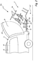
- the load carrier 10a is arranged at a rear region 11 of a motor vehicle 12.
- a support structure 13a with two longitudinal members 14a, 14b is fixed to the vehicle 12 connected to the vehicle.
- the side members 14a, 14b are inserted in schematically illustrated receptacles 57 on the body 15 from the rear.
- the support structure 13a may also be provided with a hitch bracket 16 to a ball neck 17 of a trailer hitch 18 of the motor vehicle 12 releasably secured.
- the side rails 14a, 14b and the hitch bracket 16 are connected by one or more cross members 54.
- a support assembly 19a is movably mounted with a support frame 20 between a driving position F and a loading position L.
- the carrying arrangement 19a In the loading position L, the carrying arrangement 19a is pivoted away at an angle with respect to the motor vehicle 12, so that it releases a pivoting region 21 of a tailgate 22.
- the tailgate 22 may pivot past bicycles 23 which are mounted on the support assembly 19a with sports equipment holders 24.
- the bicycles 23 are a load 34 placed on the carrying arrangement 19a.
- a pivot bearing arrangement 25 is provided between these two components.
- the pivot bearing arrangement 25 comprises two multi-joint arrangements 26a, 26b, which in the present case are configured as four-jointed joints 27a, 27b.
- the four joints 27a, 27b include pivot arms 28 and steering arms 29, which are pivotally mounted on pivot bearings 30, 31 on the longitudinal beams 14a, 14b.
- the pivot bearings 30, 31 are located at a longitudinal end of the arms 28, 29.
- At a longitudinal end opposite this longitudinal end are further pivot bearings 32, 33 between the arms 28 and 29 on the one hand and the support assembly 19 a on the other hand present.
- the support assembly would when pivoting from the driving position F in the loading position L and vice versa a parallelogram-like movement go through, ie their top would always be horizontal or at least substantially horizontal.
- the pivot arms 28 are shorter than the steering arms 29. This pivots the support assembly 19a, so that it is in the loading position L obliquely away from the rear of the vehicle 12. This measure increases the pivoting range 21.
- foot-operated devices 35a, 35b are expedient.
- the foot actuator 35a includes, for example, a pedal 36 that is operatively connected to one of the shorter pivot arms 28.
- the pedal 36 is rotatably and pivotally connected to the pivot arm 28.
- a one-piece construction, in which the pivot arm 28 is extended so to speak to the pedal 36, is conceivable.
- the pedal 36 is angled in front of the pivot arm 28. By a simple foot operation of the pedal 36, the support assembly 19a can be pivoted into the loading position L.
- His foot control device 35b includes, for example, an actuating part 37 which extends in the vehicle transverse direction of the motor vehicle 12.
- the operating member 37 is pivotally mounted on the support structure 13a.
- the actuating member 37 engages two spaced engagement points on the support assembly or the pivot bearing assembly.
- the actuating member 37 comprises a pivoting bracket 38 with arms 39, between which a pivoting bracket 38 with e.g. a foot 60 operable actuating rod 40 extends.
- the actuating rod 40 is welded, for example, to the arms 39 at one longitudinal end thereof.
- swivel bracket 38 formed from a plurality of components, an integral swivel bracket could also be provided.
- the arms 39 are pivotally mounted on the support structure 13a.
- a separate pivot bearing may be provided on the support structure for a pivotal mounting of an actuating part according to the invention.
- the arms 39 are pivotally mounted on the pivot bearing 30.
- the actuating rod 40 is pivotally mounted on the pivot bearings 30 relative to the pivot arms 28.
- a clearance 41 is present, in which the swivel bracket 38 between a rest position R, at the operating ends 42 of the arms 39 out of engagement with the pivot arms 28, and a working position A is adjustable, in which the operating ends 42 engage the pivot arms 28.
- actuation recesses 43 are provided on the actuation ends 42 for this purpose.
- the foot-operated device 35b has such a center of gravity position that it remains autonomously in the rest position R.
- the foot control device 35b is pivoted in its rest position R, for example, upwards.
- the foot actuator 35b then needs e.g. less space.
- the actuating rod 40 is in its rest position R on the two side rails 14a, 14b at positions 56a, 56b.
- the load carriers 10a, 10b have a flexible extension concept.
- the support frame 20 includes a base support 44, the provided by a support platform 53 load capacity can be increased by extension members 45.
- the extension members 45 are, for example, support rods 46 projecting rearwardly in front of the base support 44.
- support platform 53 In front of the support platform 53 are also provided as extension components supporting elements 58, e.g. for parking the bicycles 23.
- the support elements 58 are expediently telescopic and / or displaceable with respect to the base support 44, so that they can be pushed under the support platform 53 when not in use.
- the support rods 46 have a stepped or S-like course. Fastening portions 47 of the support rods 46, which have a substantially horizontal course in the driving position F, are fastened to support elements 48 of the support frame 20 extending in the vehicle longitudinal direction. Thus, the attachment portions 47 extend corresponding to the support members 48.
- the attachment portions 47 may be attached laterally to the support members 48, for example. For securing, for example, securing splines, bolts or the like may be provided.
- the attachment portions 47 may also Be L-shaped or U-shaped so that they can be saddled so to speak on the support members 48 and supported on the support members 48 at least on the upper side.
- Adjacent to the attachment portions 47 are inclined portions 49 of the support rods 46.
- the inclined sections 49 extend inclined in the driving position F obliquely away from the motor vehicle 12. At the inclined portions 49 close to support portions 50 of the support rods 46, which extend in the driving position F is substantially horizontal.
- a support platform or load supports e.g. Sports Equipment Holder 24, be attached.
- the supporting sections 50 or sports equipment holders 24 arranged thereon preferably form actuating handles for adjusting the carrier arrangement 19a from the driving position F to the loading position L and / or vice versa.
- the support sections 50 and / or the sports equipment holder 24 collar relatively large with respect to the pivot bearing 30 and thus form actuating arms or operating lever, which allow easy manual operation of the support assembly 19a in an adjustment of the driving position F in the loading position L and vice versa.
- the operability of the load carrier 10b is thus not limited, even if, for example, the foot operating part 37 is less accessible through the extension with the aid of the extension components 45.
- the support arrangement 19a can be locked with a locking device 51 with respect to the support structure 13a.
- the locking device 51 includes, for example, a but firmly connected to the support assembly 19a, but movable locking member 52, such as a locking screw or a locking bolt which engages for locking in a locking receptacle 55 of the support structure 19a.
- the support assembly 19a provides with the attached by extension members 45, a lower loading level 65 and an upper loading level 66 ready.
- a free space 67 for pivoting the carrying arrangement 19a in the direction of a road surface 69.
- the upper loading level 66 leaves a viewing area to a tail lamp assembly 70, which is arranged at the free end of the support structure 13 facing away from the motor vehicle 12.
- the tail lamp assembly 70 includes taillights 71 which are connectable to a vehicle electrical system 72, for example via a connection 73, in which a plug of the load carrier 10a is plugged into a socket of the motor vehicle 12.
- a stepped support arrangement 19c is pivotally mounted on a support structure 13c via a pivot bearing arrangement 25c.
- the support structure 13c includes, for example, side members 14c, which are inserted in receptacles at the rear of the motor vehicle 12 and / or are attached to the hitch 18, for example.
- the support structure 13c provides a horizontal support plane.
- the support structure 19c is stair-like and provides a lower and an upper loading level 65, 66 ready.
- each loading level 65, 66 are not shown in detail holder, eg sports equipment holder for example bicycles 23 fixed, releasably or movably supported.
- the lower bicycles 23 are supported on a lower platform 74 while the bicycles 23 located on the upper loading level 66 are disposed on an upper platform 75.
- the word "platform” is to be understood here in a broader sense, ie it may indeed be flat shelves, such as storage shelves or the like, be provided, or for example also holders for the wheels of the bicycles 23 on the two levels 65, 66 may be provided.
- the support assembly 19c includes frame 85, which is pivotally mounted in the manner of a rocker on the support structure 13c. Therefore, you can call the frame 85 as a rocker.
- the pivot bearing assembly 25c includes two pivot bearings 83 disposed at the free end portion of the side rails 14 and the support structure 13c, respectively.
- the pivot bearings 76 define a pivot axis 77 about which the support assembly 19c pivots between a drive position F and a loading position L.
- the pivot axis 77 extends horizontally.
- the pivot axis 77 extends relative to a vehicle longitudinal direction 78 of the motor vehicle 12 approximately in a longitudinal center between the two platforms 74 and 75.
- the pivot axis 77 extends approximately in the region of the lower loading plane 65. It is understood that a course through, for example, the upper loading level 66 is quite conceivable, for example, if an L-shaped upwardly projecting portion on the support structure 13c would project upwards.
- the approximately longitudinal arrangement of the pivot axis 77 facilitates pivoting about the pivot axis 77, because the loads 34 arranged on the two loading planes 65, 66 exert approximately the same lever arms and thus approximately similar forces on the support arrangement 19c on both sides of the pivot axis 77.
- the support arrangement 19c contains, for example, two lateral supports 79 with support sections 80, 81 which extend horizontally in the drive position F and define the loading planes 65, 66, between which connection section 82 extends.
- the carriers 79 are, for example, metal profiles or the like.
- the tail lamp assembly 70c is suitably pivotally mounted on the support structure 13c. For or when pivoting the support assembly 19c in the loading position L, the tail lamp assembly 70c is pivoted, for example, down. This is effected, for example, by the connecting section 82 acting on the tail lamp arrangement 70c from above.
- the rear light assembly 70c can pivot, for example under spring action or the like back up again in a substantially vertical, the driving position F associated driving position.
- the load carrier 10d has a fixed step-shaped support structure 84 with a lower and an upper loading plane 65 and 66, which are provided by a support structure 13d. From the motor vehicle 12 fasten longitudinal members 14d are stepped support 79d backwards above.
- the lower loading level is defined by the longitudinal beams 14d, the upper loading level 66 provided by the beams 79d.
- the support sections 80, 81 are substantially the same length, so that it is approximately the same size on the loading levels 65, 66 waiting load capacity.
Abstract
Description
Die Erfindung betrifft einen Lastenträger für ein Kraftfahrzeug, insbesondere einen Personenkraftwagen, mit einer Tragstruktur zum Tragen einer Last, die in einer Arbeitsstellung des Lastenträgers nach hinten vor einen Heckbereich des Kraftfahrzeugs vorsteht, gemäß dem Oberbegriff des Anspruchs 1.The invention relates to a load carrier for a motor vehicle, in particular a passenger car, having a support structure for carrying a load, which protrudes in a working position of the load carrier to the rear in front of a rear portion of the motor vehicle, according to the preamble of claim 1.
Ein derartiger Lastenträger geht z.B. aus
Der Lastenträger verdeckt in seiner Arbeitsstellung, wenn er an dem Kraftfahrzeug angeordnet ist, eine Heckleuchtenanordnung des Personenkraftwagens. Von hinten sind somit die Heckleuchten des Kraftfahrzeuges nicht mehr sichtbar. Lastenträger haben daher eigene Heckleuchtenanordnungen, die mit dem Bordnetz des Kraftfahrzeuges verbunden werden und sichtbar sind. Die an exponierter Stelle hinten am Lastenträger angeordnete Heckleuchtenanordnungen sind jedoch anfällig für Beschädigungen, beispielsweise beim Rangieren mit dem Kraftfahrzeug.The load carrier concealed in its working position, when it is arranged on the motor vehicle, a tail lamp arrangement of the passenger car. From behind the tail lights of the vehicle are thus no longer visible. Load carriers therefore have their own tail light assemblies, which are connected to the electrical system of the motor vehicle and are visible. However, arranged at an exposed point on the rear of the load carrier tail lamp assemblies are prone to damage, for example when maneuvering with the motor vehicle.
Es ist daher die Aufgabe der Erfindung, einen Lastenträger mit einer verbesserten Handhabbarkeit bereitzustellen.It is therefore the object of the invention to provide a load carrier with improved handling.
Zur Lösung der Aufgabe ist ein Lastenträger gemäß der technischen Lehre des Anspruchs 1 vorgesehenTo solve the problem, a load carrier according to the technical teaching of claim 1 is provided
Unter der oberen Ladeebene bleibt beispielsweise ein Blickbereich für eine Heckleuchtenanordnung frei.Below the upper loading level, for example, a viewing area for a tail lamp arrangement remains free.
Zwischen der oberen und der unteren Ladeebene kann auch mindestens eine Zwischenebene vorgesehen sein, z.B. in der Art einer Treppenstruktur.Between the upper and lower loading levels, at least one intermediate level can also be provided, e.g. in the manner of a staircase structure.
Die untere Ladeebene und die obere Ladeebene können unterschiedliche Ladekapazitäten aufweisen. Vorzugsweise haben die untere und die obere Ladeebene jedoch im wesentlichen dieselbe die Ladekapazität. Beispielsweise sind die beiden Ladeebenen in Fahrzeuglängsrichtung im wesentlichen gleich lang.The lower loading level and the upper loading level may have different loading capacities. Preferably, however, the lower and upper loading levels have substantially the same loading capacity. For example, the two loading levels in the vehicle longitudinal direction are substantially the same length.
Die obere Ladeebene kragt vorteilhaft verhältnismäßig weit nach hinten vor die untere Ladeebene vor, sodass der Schutz der Heckleuchtenanordnung gewährleistet ist. Dennoch bleibt die Heckleuchtenanordnung, die mit dem Bordnetz des Kraftfahrzeuges verbindbar ist, zugänglich.Advantageously, the upper loading plane protrudes relatively far backwards in front of the lower loading plane, so that the protection of the rear lamp arrangement is ensured. Nevertheless, the tail light assembly, which is connectable to the electrical system of the motor vehicle, accessible.
An der Tragstruktur ist eine Heckleuchtenanordnung angeordnet. Die Heckleuchtenanordnung ist unterhalb der oberen Ladeebene und vom hinteren, freien Ende des Lastenträgers entfernt näher beim Fahrzeugheck angeordnet. Vorteilhaft ist es, wenn die obere Ladeebene derart oberhalb der unteren Ladeebene angeordnet ist, dass ein Blickbereich zu der Heckleuchtenanordnung frei bleibt. Die Heckleuchtenanordnung ist unterhalb der oberen Ladeebene, d.h. zum Kraftfahrzeug zurückversetzt angeordnet, sodass sie vor Beschädigungen geschützt ist.On the support structure, a rear light assembly is arranged. The tail light assembly is located below the upper deck level and from the rear, free end of the load carrier closer to the rear of the vehicle. It is advantageous if the upper loading level is arranged above the lower loading level in such a way that a viewing area to the rear light arrangement remains free. The tail lamp assembly is below the upper deck level, i. placed back to the motor vehicle, so that it is protected from damage.
Die untere und/oder die obere Ladeebene können bezüglich der Tragstruktur ortsfest sein. Beispielsweise können fest an der Tragstruktur angeordnete Ladeplattformen, Halterungen für Sportgeräte oder dergleichen vorgesehen sein.The lower and / or the upper loading level may be stationary relative to the support structure. For example, it is possible to provide loading platforms, supports for sports equipment or the like arranged fixedly on the support structure.
Vorteilhaft ist auch ein modulares Erweiterungskonzept, bei dem mindestens ein Erweiterungsbauteil an einem Basis-Träger des Lastenträgers anordenbar oder daran beweglich gelagert ist. Der Basis-Träger bildet z.B. einen Bestandteil der Tragstruktur oder einer bezüglich der Tragstruktur beweglichen Trageanordnung. Auf diese Weise lässt sich die Ladekapazität des Trägers bei Bedarf vergrößern.Also advantageous is a modular expansion concept, in which at least one expansion component is mounted on a base carrier of the load carrier or mounted movably thereto. The base support forms e.g. a part of the support structure or a supporting structure movable with respect to the support structure. In this way, the loading capacity of the carrier can be increased if necessary.
Das Erweiterungsbauteil steht beispielsweise in seiner Gebrauchsstellung seitlich, nach hinten oder nach oben vor die Trageanordnung vor.The extension member is, for example, in its position of use laterally, backwards or upwards in front of the support assembly.
Das Erweiterungsbauteil umfasst einen oder vorzugsweise zwei S-artige oder S-förmige Trägerstäbe. Die S-artigen Trägerstäbe sind vorzugsweise seitlich an dem Basisträger lösbar befestigbar. Durch die S-Form stehen die Trägerstäbe nach schräg hinten oben vor. An dem mindestens einen Erweiterungsbauteil ist beispielsweise mindestens eine weitere Tragplattform oder mindestens eine weitere Sportgerätehalterung anbringbar oder angebracht.The extension member comprises one or preferably two S-shaped or S-shaped support rods. The S-like support rods are preferably laterally releasably attachable to the base support. Due to the S-shape, the support rods project obliquely behind at the top. For example, at least one further supporting platform or at least one further sports equipment holder can be attached or attached to the at least one expansion component.
Das Erweiterungsbauteil bildet vorzugsweise eine Betätigungshandhabe zum Verlagern der Trageanordnung in die Ladestellung oder die Fahrstellung. Es kann auch eine Betätigungshandhabe, z.B. ein Handgriff, an dem Erweiterungsbauteil angeordnet sein.The extension component preferably forms an actuating handle for displacing the carrying arrangement into the loading position or the driving position. There may also be an actuating handle, e.g. a handle, be arranged on the extension member.
Das mindestens eine Erweiterungsbauteil stellt zweckmäßigerweise die obere Ladeebene bereit. Das Erweiterungsbauteil steht in der Gebrauchsstellung nach hinten oben vor die beispielsweise die Trageanordnung oder die Tragstruktur vor.The at least one extension component expediently provides the upper loading level. The extension member is in the use position to the rear above before, for example, the support assembly or the support structure.
Die obere Ladeebene kann beispielsweise eine durchgehende Ladeplattform umfassen.The upper loading level may for example comprise a continuous loading platform.
Vorteilhaft ist bei einem erfindungsgemäßen Lastenträger, wenn er eine bezüglich der Tragstruktur zwischen einer für einen Fahrbetrieb des Kraftfahrzeugs vorgesehenen Fahrstellung und einer zum Be- und Entladen des Kraftfahrzeugs vorgesehenen Ladestellung verstellbare Trageanordnung zum Auflegen der Last aufweist, wobei die Trageanordnung mit der auf ihr angeordneten Last in der Ladestellung einen Schwenkbereich einer Heckklappe oder einer Hecktür des Kraftfahrzeugs freigibt. Die Trageanordnung umfasst vorzugsweise einen Fahrradträger, eine Trägerplattform zum Auflegen von Lasten oder dergleichen.It is advantageous in a load carrier according to the invention, if it has a respect to the support structure between a provided for a driving operation of the motor vehicle driving position and a loading and unloading of the motor vehicle provided loading position adjustable support arrangement for placing the load, wherein the support assembly with the load arranged on it releases in the loading position a swivel range of a tailgate or a rear door of the motor vehicle. The support structure preferably comprises a bicycle carrier, a carrier platform for placing loads or the like.
Ein Grundgedanke ist dabei, eine Tragstruktur sozusagen fahrzeugfest zu belassen, beispielsweise nach hinten vorstehende Träger oder Trägerarme, und auf dieser Tragstruktur die eigentliche Trageanordnung beweglich zu lagern. Die Trageanordnung kann von der Fahrstellung in die Ladestellung verlagert werden, ohne dass man die auf ihr aufliegende Last entfernen muss. Die Last kann auf der Trageanordnung verbleiben.A basic idea is to leave a support structure so to speak vehicle-fixed, for example, rearwardly projecting carrier or support arms, and to store on this support structure, the actual support assembly movable. The support assembly can be moved from the driving position to the loading position without having to remove the load resting on it. The load may remain on the support structure.
Prinzipiell ist es z.B. möglich, eine oder die Heckleuchtenanordnung an der Tragstruktur oder der beweglichen Trageanordnung anzuordnen, z.B. hinter der unteren oder auch der oberen Ladeebene.In principle, it is e.g. it is possible to arrange one or the tail lamp arrangement on the support structure or the movable support arrangement, e.g. behind the lower or the upper loading level.
Die Tragstruktur untergreift die Trageanordnung zweckmäßigerweise zumindest in der Fahrstellung. Die Trageanordnung liegt vorteilhaft zumindest in der Fahrstellung auf der Tragstruktur auf, z.B. direkt oder indirekt. Indirekt z.B. auf einer Linearführung oder einer Schwenklageranordnung. Es ist vorteilhaft, wenn die Trageanordnung auch in der Ladestellung zumindest teilweise oberhalb der Tragstruktur angeordnet ist.The support structure expediently engages under the support arrangement, at least in the driving position. The support arrangement is advantageously at least in the driving position on the support structure, e.g. directly or indirectly. Indirectly e.g. on a linear guide or a pivot bearing arrangement. It is advantageous if the support arrangement is arranged at least partially above the support structure even in the loading position.
Für eine lineare Verfahrbarkeit können beispielsweise eine Linearführung und/oder ein Fahrwagen vorgesehen sein. Besonders bevorzugt ist jedoch eine Schwenklageranordnung, mit der die Trageanordnung schwenkbar an der Tragstruktur gelagert ist. Es versteht sich, dass eine Schwenklageranordnung auch mit Hilfe einer Linearführung zusätzlich linear verfahrbar sein kann.For a linear mobility, for example, a linear guide and / or a carriage can be provided. However, particularly preferred is a pivot bearing arrangement with which the support assembly is pivotally mounted on the support structure. It is understood that a pivot bearing arrangement can also be linearly movable with the aid of a linear guide.
Es ist möglich, dass die Trageanordnung auf einem Verstellweg zwischen der Fahrstellung und der Ladestellung eine überlagerte Linear- und Schwenkbewegung durchführt.It is possible that the support assembly performs a superimposed linear and pivotal movement on an adjustment between the driving position and the loading position.
Die Trageanordnung nimmt in der Ladestellung zweckmäßigerweise eine vom Kraftfahrzeug abgewandte Schrägstellung ein. Beispielsweise ist die Trageanordnung in der Ladestellung von dem Kraftfahrzeug weg geschwenkt.The support assembly takes in the loading position expediently a remote from the motor vehicle skew. For example, the support assembly is pivoted away in the loading position of the motor vehicle.
Die Trageanordnung kann in der Art einer Wippe ausgebildet sein.The support assembly may be formed in the manner of a rocker.
Eine erste Wipparmanordnung kann einerseits der Schwenklagerung die untere Ladeebene definieren und eine zweite Wipparmanordnung andererseits der Schwenklagerung die obere Ladeebene definieren. Es ist bei einer wippenartigen Trageanordnung prinzipiell auch möglich, dass die erste und die zweite Wipparmanordnung einen umgekehrten Höhenversatz oder keinen Höhenversatz aufweisen, so dass sie in der Fahrstellung beispielsweise etwa denselben Abstand zu einer Fahrbahnoberfläche haben.A first Wipparmanordnung can on the one hand define the pivot bearing the lower loading level and a second Wipparmanordnung the other part of the pivot bearing define the upper loading level. It is in principle also possible with a rocker-like support arrangement that the first and the second rocker arm arrangement have a reversed vertical offset or no height offset, so that they have approximately the same distance to a road surface in the driving position, for example.
Die untere und/oder die obere Ladeebene sind zweckmäßigerweise an der beweglichen Trageanordnung angeordnet. Es versteht sich, dass auch beispielsweise die untere Ladeebene durch die Tragstruktur bereitgestellt werden kann, während die obere Ladeebene eine schwenkbare oder linear verfahrbare Ladeebene bildet, die relativ zu der unteren Ladeebene beweglich ist. Eine Schwenkachse der Schwenklageranordnung verläuft bezüglich der Fahrzeuglängsrichtung des Kraftfahrzeuges zweckmäßigerweise zwischen einem dem Fahrzeugheck zugewandten Längsendbereich der unteren Ladeebene und einem freien, vom Fahrzeugheck abgewandten Endbereich der oberen Ladeebene. Auf diese Weise ist es möglich, einen Freiraum unterhalb der oberen Ladeebene für eine Schwenkbewegung zu nutzen. Die Schwenkachse kann zwar horizontal schräg und/oder schräg zur Fahrzeugquerrichtung verlaufen. Bevorzugt ist aber ein etwa horizontaler Verlauf.The lower and / or the upper loading level are expediently arranged on the movable support arrangement. It is understood that, for example, the lower loading level can be provided by the support structure, while the upper loading level forms a pivotable or linearly movable loading level, which is movable relative to the lower loading level. With reference to the vehicle longitudinal direction of the motor vehicle, a pivot axis of the pivot bearing arrangement expediently extends between a longitudinal end region of the lower loading plane facing the rear of the vehicle and a free end region of the upper loading plane facing away from the rear of the vehicle. In this way it is possible to use a free space below the upper loading level for a pivoting movement. Although the pivot axis may be horizontal obliquely and / or obliquely to the vehicle transverse direction. But is preferably an approximately horizontal course.
Die jeweilige Schwenkachse kann beispielsweise im Bereich der unteren Ladeebene verlaufen. Aber auch im Bereich zwischen den beiden unteren und oberen Ladeebenen oder an der oberen Ladeebene kann eine Schwenkachse vorgesehen sein.The respective pivot axis can run, for example, in the region of the lower loading level. But even in the area between the two lower and upper loading levels or at the upper loading level, a pivot axis may be provided.
Zweckmäßigerweise verläuft die jeweilige Schwenkachse etwa im Bereich einer Längsmitte zwischen der unteren und der oberen Ladeebene. Somit ist die Trageanordnung mit und ohne Last zweckmäßigerweise im wesentlichen ausbalanciert. Es versteht sich, dass hier auch eine eindeutige Kipp-Lage vorteilhaft sein kann, d.h. dass die Trageanordnung um die Schwenkachse in die Ladestellung oder die Freigabestellung selbsttätig schwenkt und dort verbleibt. Zumindest in der jeweils anderen Stellung wird die Trageanordnung dann vorteilhaft durch eine Verriegelungs- oder Halteeinrichtung gehalten.Conveniently, the respective pivot axis extends approximately in the region of a longitudinal center between the lower and the upper loading level. Thus, the support assembly is expediently substantially balanced with and without load. It is understood that here also a unique tilt position can be advantageous, i. that the support assembly pivots about the pivot axis in the loading position or the release position automatically and remains there. At least in the other position, the support assembly is then advantageously held by a locking or holding device.
Die Schwenkachse verläuft zweckmäßigerweise durch ein Schwenklager oder ein Schwenklagerpaar der Schwenklageranordnung bzw. wird durch dieses Schwenklager definiert. Vorzugsweise ist dann nur eine einzige Schwenkachse vorhanden.The pivot axis expediently passes through a pivot bearing or a pivot bearing pair of the pivot bearing arrangement or is defined by this pivot bearing. Preferably then only a single pivot axis is present.
Es ist auch möglich, dass zum Schwenken der Trageanordnung bezüglich der Tragstruktur mehrere Schwenkachsen vorhanden sind. Es sind aber auch eine oder mehrere räumlich von der Schwenklageranordnung entfernte Schwenkachsen möglich. Diese mindestens eine Schwenkachse kann raumfest oder im Raum beweglich, d.h. nicht raumfest sein.It is also possible that for pivoting the support assembly with respect to the support structure a plurality of pivot axes are present. But there are also one or more spatially remote from the pivot bearing assembly pivot axes possible. This at least one pivot axis may be fixed in space or movable in space, ie not be room-solid.
Vorzugsweise umfasst die Schwenklageranordnung z.B. eine Mehrgelenkanordnung. Beispielsweise sind zwei voneinander in Fahrzeugquerrichtung beabstandete Mehrgelenke zum Schwenken der Trageanordnung bezüglich der Tragstruktur vorgesehen.Preferably, the pivot bearing assembly comprises e.g. a multi-joint arrangement. For example, two spaced apart in the vehicle transverse direction of multi-joints are provided for pivoting the support assembly with respect to the support structure.
Besonders bevorzugt ist eine Viergelenkanordnung bzw. ein Viergelenk. Es ist auch möglich, mehr oder weniger als 4 Gelenke vorzusehen.Particularly preferred is a four-bar arrangement or a four-bar linkage. It is also possible to provide more or less than 4 joints.
Das Viergelenk kann dazu ausgestaltet sein, dass die Trageanordnung sowohl in der Fahrstellung als auch in der Ladestellung eine im Wesentlichen horizontale Position einnimmt.The four-bar linkage can be designed such that the carrying arrangement assumes a substantially horizontal position both in the driving position and in the loading position.
Aber auch ein Schwenken in eine Schrägstellung zumindest eine leicht geneigte Schrägstellung, ist vorteilhaft. Beispielsweise umfasst die Mehrgelenkanordnung einen von dem Heckbereich entfernten Schwenkarm und eine näher beim Heckbereich angeordneten Lenkarm, wobei der Lenkarm länger als der Schwenkarm ist. Dadurch macht die Trageanordnung beim Verstellen von der Fahrstellung in die Ladestellung eine Schwenkbewegung, allerdings mit einem größeren Schwenkradius, als dies bei nur einen einzigen Schwenkachse der Fall wäre.But even pivoting in an inclined position, at least a slightly inclined inclination, is advantageous. By way of example, the multi-joint arrangement comprises a swivel arm remote from the rear area and a steering arm arranged closer to the rear area, the steering arm being longer than the swivel arm. This makes the support assembly during adjustment of the driving position in the loading position a pivoting movement, but with a larger swing radius than would be the case with only a single pivot axis.
Die Trageanordnung hat zweckmäßigerweise zumindest im beladenen Zustand eine solche Schwerpunktlage, dass sie selbsttätig in der Fahrstellung und/oder in der Ladestellung bleibt. Die Trageanordnung bleibt also hier ohne eine zusätzliche Halterung oder Stütze in der jeweiligen Fahrstellung oder Ladestellung. Zweckmäßigerweise durchläuft die Trageanordnung zwischen der Fahrstellung und der Ladestellung einen Verstellweg mit einem Kipppunkt. Die Trageanordnung kippt dann sozusagen in die Fahrstellung oder die Ladestellung.The support assembly has expediently at least in the loaded state such a center of gravity position that it automatically remains in the driving position and / or in the loading position. The support structure thus remains here without an additional support or support in the respective driving position or loading position. Conveniently, the support assembly passes between the driving position and the loading position an adjustment with a tipping point. The support assembly tilts then, so to speak, in the driving position or the loading position.
Es versteht sich, dass zum Halten in der Fahrstellung und/oder in der Ladestellung Stützen, Halterungen oder dergleichen vorteilhaft sind. Diese können auch als zusätzliche Sicherheitsmaßnahme vorgesehen sein.It is understood that for holding in the driving position and / or in the loading position supports, brackets or the like are advantageous. These can also be provided as an additional security measure.
Es versteht sich, dass auch die Heckleuchtenanordnung verschwenkbar oder in sonstiger Weise beweglich an dem Lastenträger angeordnet sein kann, beispielsweise an dessen Tragstruktur. Eine bewegliche, insbesondere schwenkbewegliche Heckleuchtenanordnung kann beispielsweise einen Schwenkweg zum Verschwenken der Trageanordnung freigeben.It is understood that the tail lamp assembly can be arranged to be pivotable or otherwise movable on the load carrier, for example, on the support structure. A movable, in particular pivotable tail lamp arrangement can release, for example, a pivoting path for pivoting the support assembly.
Es bildet einen eigenständigen erfindungsgemäßen Grundgedanken, wenn eine bezüglich einer Tragstruktur eines Lastenträgers bewegliche Trageanordnung eine untere erste und eine obere, vom Fahrzeugheck entferntere zweite Ebene aufweist. Ein Grundgedanke ist dabei, dass die obere Ladeebene weiter von der Fahrbahnoberfläche entfernt ist als die untere Ladeebene, sodass unterhalb der oberen Ladeebene unterhalb der Trageanordnung ein größerer Bewegungsbereich, insbesondere Schwenkbereich, frei bleibt.It forms an independent basic idea according to the invention, when a support arrangement which is movable relative to a support structure of a load carrier has a lower first and an upper, second, plane remote from the rear of the vehicle. A basic idea is that the upper loading level is further away from the road surface than the lower loading level, so that below the upper loading level below the carrying arrangement, a larger range of movement, in particular pivoting, remains free.
Eine Heckleuchtenanordnung kann, muss aber nicht an der Tragstruktur angeordnet sein. Sie könnte beispielsweise auch an der Trageanordnung angeordnet sein.A tail lamp assembly may, but need not be, disposed on the support structure. It could for example also be arranged on the support arrangement.
Vorteilhaft ist eine Fußbetätigungseinrichtung zum Betätigen der Trageanordnung. Bei einer Fußbetätigung stehen verhältnismäßig große Betätigungskräfte zur Verfügung.Advantageously, a foot control device for actuating the support assembly. In a foot operation are relatively large actuation forces available.
Die Fußbetätigungseinrichtung wirkt z.B. auf die bezüglich der Tragstruktur beweglich gelagerte Trageanordnung. Beispielsweise ist die Fußbetätigungseinrichtung mit der Trageanordnung fest oder gelenkig verbunden oder gleitet an der Trageanordnung zu deren Betätigung entlang.The foot actuator acts e.g. on the support structure with respect to the movably mounted support structure. For example, the foot control device with the support assembly is fixed or hinged or slides along the support assembly to the actuation along.
Es ist auch möglich, dass die Fußbetätigungseinrichtung z.B. eine Linearführung und/oder Schwenklageranordnung zur beweglichen Lagerung der Trageanordnung bezüglich der Tragstruktur wirkt. Z.B. kann die Fußbetätigungseinrichtung auf einen Schwenkarm der Schwenklageranordnung, insbesondere der Mehrgelenkanordnung oder eines einzelnen Schwenklagers, wirken. Die Fußbetätigungseinrichtung ist z.B. mit einem Schwenkarm fest oder gelenkig verbunden oder wird durch einen Schwenkarm gebildet.It is also possible that the foot control device e.g. a linear guide and / or pivot bearing arrangement for the movable mounting of the support assembly with respect to the support structure acts. For example, For example, the foot operating device may act on a pivot arm of the pivot bearing arrangement, in particular the multi-joint arrangement or a single pivot bearing. The foot control device is e.g. connected to a swivel arm fixed or hinged or is formed by a pivoting arm.
Die Fußbetätigungseinrichtung hat zweckmäßigerweise einen Freigang, so dass sie zwischen einer Ruhestellung, bei der sie außer Eingriff mit der Trageanordnung ist, und einer Arbeitsstellung verstellbar ist, bei der sie zum Verstellen der Trageanordnung mit dieser in Eingriff ist.The foot control device has expediently a clearance, so that it is adjustable between a rest position in which it is out of engagement with the support assembly, and a working position in which it is for adjusting the support assembly with this engaged.
Vorzugsweise ist eine Verriegelungseinrichtung zum Verriegeln der Trageanordnung bezüglich der Tragstruktur zumindest in der Fahrstellung vorgesehen. Ein unbeabsichtigtes Schwenken oder lineares Verfahren der Trageanordnung, was im Fahrbetrieb gefährlich sein könnte, wird durch die Verriegelungseinrichtung verhindert.Preferably, a locking device for locking the support assembly with respect to the support structure is provided at least in the driving position. Unintentional pivoting or linear movement of the support structure, which could be dangerous when driving, is prevented by the locking device.
Der Lastenträger, insbesondere die bewegliche Trageanordnung, kann beispielsweise eine Trägerplattform zum Abstellen der Last und/oder eine Sportgerätehalterung umfassen. Die Sportgerätehalterung ist beispielsweise eine Fahrradhalterung. Es versteht sich, dass Sportgerätehalterungen zweckmäßigerweise lösbar mit der Trageanordnung verbindbare Bauteile sind.The load carrier, in particular the movable support arrangement, may for example comprise a carrier platform for parking the load and / or a sports equipment holder. The sports equipment holder is for example a bicycle holder. It is understood that sports equipment holders are expediently releasably connectable to the support assembly components.
Die Tragstruktur enthält z.B. ein an dem Kraftfahrzeug verschieblich angeordnetes Trägerteil. Beispielsweise ist das verschiebliche Trägerteil ein an der Karosserie des Fahrzeugs nach hinten ausziehbares Trägerteil, ein Schwenkteil oder dergleichen. Besonders bevorzugt ist es, wenn das Trägerteil eine Art Schublade bildet.The support structure contains e.g. a displaceably arranged on the motor vehicle carrier part. For example, the displaceable support part is a carrier part, which can be pulled out to the rear on the body of the vehicle, a pivoting part or the like. It is particularly preferred if the carrier part forms a kind of drawer.
Die Tragstruktur umfasst zweckmäßigerweise mindestens zwei in Fahrzeugquerrichtung zueinander beabstandete Trägerelemente oder Trägerstäbe.The support structure expediently comprises at least two support elements or support rods spaced from one another in the vehicle transverse direction.
Diese Trägerelemente sind beispielsweise in Aufnahmen einsteckbar, beispielsweise durch einen Stoßfänger des Kraftfahrzeuges hindurch. Zweckmäßigerweise sind die Aufnahmen mit Längsträgern einer Karosserie des Kraftfahrzeugs verbunden.These support elements can be plugged into receptacles, for example, through a bumper of the motor vehicle, for example. Appropriately, the recordings are connected to longitudinal members of a body of the motor vehicle.
Alternativ ist es auch denkbar, dass die Tragstruktur eine Halterung zum lösbaren Anordnen an einer Anhängekupplung des Kraftfahrzeugs aufweist.Alternatively, it is also conceivable that the support structure has a holder for releasably arranging on a trailer coupling of the motor vehicle.
Es stellt an sich einen eigenständigen Gedanken dar, eine Trageanordnung zum Tragen einer Last in der Art einer Wippe an einer Tragstruktur eines Lastenträgers gemäß dem Oberbegriff des Anspruchs 1 zwischen einer für einen Fahrbetrieb des Kraftfahrzeugs vorgesehenen Fahrstellung und einer zum Be- und Entladen des Kraftfahrzeugs vorgesehenen Ladestellung um eine Schwenkachse schwenkbar zu lagern, wobei die Trageanordnung eine näher beim Fahrzeugheck angeordnete Ladeebene und eine vom Fahrzeugheck entferntere Ladeebene aufweist und wobei die Schwenkachse zwischen den Ladeebenen verläuft. Dabei ist es möglich, dass in der Fahrstellung:
- beide Ladeebenen auf einer Ebene sind, z.B. im wesentlichen horizontal verlaufen,
- in der oben beschriebenen Weise die dem Kraftfahrzeug nähere Ladeebene unterhalb der vom Kraftfahrzeug entfernteren Ladeebene angeordnet ist oder
- die näher beim Fahrzeugheck angeordnete Ladeebene eine obere Ladeebene und die vom Fahrzeugheck entferntere Ladeebene eine untere Ladeebene bilden. Die Schwenkachse kann bei der Wippen-Trageanordnung eine einzige raumfest Achse oder eine räumlich bewegliche Achse sein, z.B. bei einer Lagerung an einem Mehrgelenk. Zudem ist zusätzlich zu der Schwenklagerung eine Linearlagerung der Trageanordnung möglich, so dass eine bezüglich des Schwenkens sequentielle oder überlagerte Linearbewegung möglich ist. Ferner ist es zwar vorteilhaft, aber nicht zwingend nötig, dass die Schwenkachse der Wippen-Trageanordnung etwa im Bereich einer Längsmitte zwischen der dem Kraftfahrzeug näheren Ladeebene und der vom Kraftfahrzeug entfernteren Ladeebene verläuft. Der Lastenträger kann mit weitere der obengenannten Merkmale aufweisen, z.B. eine Verriegelung für die Fahrstellung, eine Heckleuchtenanordnung, eine Halterung zum lösbaren Anordnen an einer Anhängekupplung oder Steckenden zum Stecken an ein Heck eines Kraftfahrzeugs, eine Schiebelagerung am Kraftfahrzeug oder dergleichen.
- both loading levels are on one level, eg substantially horizontal,
- in the manner described above closer to the motor vehicle Loading level is arranged below the remote from the motor vehicle loading level or
- the loading level arranged closer to the rear of the vehicle forms an upper loading level and the loading level further away from the rear of the vehicle forms a lower loading level. The pivot axis may be a single spatially fixed axis or a spatially movable axis in the rocker support assembly, for example, when stored at a multi-joint. In addition, in addition to the pivot bearing, a linear mounting of the support assembly is possible, so that with respect to the pivoting sequential or superimposed linear movement is possible. Furthermore, although it is advantageous, but not absolutely necessary, that the pivot axis of the rocker support assembly extends approximately in the region of a longitudinal center between the loading plane closer to the motor vehicle and the loading plane farther from the motor vehicle. The load carrier may have with further of the above features, for example, a lock for the driving position, a tail lamp assembly, a holder for releasable placement on a trailer hitch or plug-in ends for insertion on a rear of a motor vehicle, a sliding bearing on the motor vehicle or the like.
Nachfolgend werden Ausführungsbeispiele der Erfindung anhand der Zeichnung erläutert. Es zeigen:
- Figur 1
- eine schematische Seitenansicht eines ersten Ausführungsbeispiels eines erfindungsgemäßen Lastenträgers in Fahrstellung,
- Figur 2
- den Lastenträger gemäß
Figur 1 in Ladestellung, - Figur 3
- den Lastenträger gemäß
Figur 1 mit nur einer Ladeebene . - Figur 4
- eine perspektivische Fahrstellungsansicht eines zweiten Ausführungsbeispiels der Erfindung in Gestalt eines Lastenträgers, der wie der Lastenträger aus
Figur 3 nur eine Ladeebene aufweist, aber z.B. mit Erweiterungsbauteilen um weitere Ladeebene erweiterbar ist, - Figur 5
- den Lastenträger gemäß
Figur 4 in Ladestellung, - Figur 6
- eine schematische Seitenansicht eines dritten Ausführungsbeispiels eines erfindungsgemäßen Lastenträgers in Fahrstellung,
- Figur 7
- den Lastenträger gemäß
Figur 6 in Ladestellung, und - Figur 8
- einen Lastenträger mit einer feststehenden, stufenförmigen Trägerstruktur mit zwei Ladeebenen.
- FIG. 1
- a schematic side view of a first embodiment of a load carrier according to the invention in the driving position,
- FIG. 2
- according to the load carrier
FIG. 1 in loading position, - FIG. 3
- according to the load carrier
FIG. 1 with only one loading level. - FIG. 4
- a perspective Fahrstellungsansicht a second embodiment of the invention in shape a load carrier that looks like the load carrier
FIG. 3 has only one loading level but, for example, can be extended by another loading level with extension components, - FIG. 5
- according to the load carrier
FIG. 4 in loading position, - FIG. 6
- a schematic side view of a third embodiment of a load carrier according to the invention in the driving position,
- FIG. 7
- according to the load carrier
FIG. 6 in loading position, and - FIG. 8
- a load carrier with a fixed, stepped support structure with two loading levels.
Bei den nachfolgend anhand von Lastenträgern 10a, 10b, 10c und 10d beschriebenen Ausführungsbeispielen sind gleiche Komponenten mit denselben Bezugszeichen versehen. Für den Lastenträger 10a spezifische Bauteile sind mit "a" gekennzeichnet, für die Lastenträger 10b, 10c und 10d spezifische Bauteile mit "b", "c" und "d".In the embodiments described below on the basis of
Der Lastenträger 10a ist einem Heckbereich 11 eines Kraftfahrzeugs 12 angeordnet. Eine Tragstruktur 13a mit zwei Längsträgern 14a, 14b ist fahrzeugfest mit dem Kraftfahrzeug 12 verbunden.The
Beispielsweise sind die Längsträger 14a, 14b in schematisch dargestellte Aufnahmen 57 an der Karosserie 15 von hinten her eingesteckt.For example, the
Die Tragstruktur 13a kann auch mit einer Anhängekupplungs-Halterung 16 an einem Kugelhals 17 einer Anhängekupplung 18 des Kraftfahrzeugs 12 lösbar befestigt sein. Die Längsträger 14a, 14b und die Anhängekupplungs-Halterung 16 sind durch einen oder mehrere Querträger 54 verbunden.The support structure 13a may also be provided with a
An den Längsträgern 14 ist eine Trageanordnung 19a mit einem Tragegestell 20 zwischen einer Fahrstellung F und einer Ladestellung L beweglich gelagert. In der Ladestellung L ist die Trageanordnung 19a bezüglich des Kraftfahrzeugs 12 nach schräg hinten weg geschwenkt, so dass sie einen Schwenkbereich 21 einer Heckklappe 22 frei gibt. Die Heckklappe 22 kann an Fahrrädern 23 vorbeischwenken, die auf der Trageanordnung 19a mit Sportgerätehaltern 24 befestigt sind. Die Fahrräder 23 sind eine auf der Trageanordnung 19a abgestellte Last 34.On the longitudinal members 14, a
Zum Verstellen, insbesondere zum Schwenken, der Trageanordnung 19a bezüglich der Tragstruktur 13a ist zwischen diesen beiden Bauteilen eine Schwenklageranordnung 25 vorgesehen.For adjusting, in particular for pivoting, the
Die Schwenklageranordnung 25 umfasst zwei Mehrgelenkanordnungen 26a, 26b, die vorliegend als Viergelenke 27a, 27b ausgestaltet sind.The
Die Viergelenke 27a, 27b enthalten Schwenkarme 28 und Lenkarme 29, die an Schwenklagern 30, 31 schwenkbar an den Längsträgern 14a, 14b gelagert sind. Die Schwenklager 30, 31 befinden sich an einem Längsende der Arme 28, 29. An einem diesem Längsende entgegengesetzten Längsende sind weitere Schwenklager 32, 33 zwischen den Armen 28 und 29 einerseits und der Trageanordnung 19a andererseits vorhanden.The four joints 27a, 27b include
Wenn gleich lange Schwenkarme und Lenkarme vorgesehen sind, würde die Trageanordnung beim Schwenken von der Fahrstellung F in die Ladestellung L und umgekehrt eine parallelogrammartige Bewegung durchlaufen, d.h. ihre Oberseite wäre stets horizontal oder zumindest im Wesentlichen horizontal.If the same length pivot arms and steering arms are provided, the support assembly would when pivoting from the driving position F in the loading position L and vice versa a parallelogram-like movement go through, ie their top would always be horizontal or at least substantially horizontal.
Beim Ausführungsbeispiel sind allerdings die Schwenkarme 28 kürzer als die Lenkarme 29. Dadurch schwenkt die Trageanordnung 19a, so dass sie in der Ladestellung L schräg vom Fahrzeugheck des Kraftfahrzeugs 12 weg steht. Diese Maßnahme vergrößert den Schwenkbereich 21.In the embodiment, however, the
Zum Betätigen der Trageanordnung 19a, insbesondere zum Verlagern der Fahrstellung F in die Ladestellung L, sind Fußbetätigungseinrichtungen 35a, 35b zweckmäßig.For actuating the
Die Fußbetätigungseinrichtung 35a enthält beispielsweise ein Pedal 36, das mit einem der kürzeren Schwenkarme 28 wirkverbunden ist. Zweckmäßigerweise ist das Pedal 36 drehfest und schwenkfest mit dem Schwenkarm 28 verbunden. Auch eine einstückige Bauweise, bei der der Schwenkarm 28 sozusagen zu dem Pedal 36 hin verlängert ist, ist denkbar.The foot actuator 35a includes, for example, a pedal 36 that is operatively connected to one of the
Das Pedal 36 steht winkelig vor den Schwenkarm 28 vor. Durch eine einfache Fußbetätigung des Pedals 36 kann die Trageanordnung 19a in die Ladestellung L geschwenkt werden.The
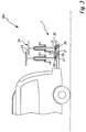
Bei dem Lastenträger 10b ist ein alternatives Betätigungskonzept vorgesehen. Seine Fußbetätigungseinrichtung 35b umfasst beispielsweise ein Betätigungsteil 37, das in Fahrzeugquerrichtung des Kraftfahrzeugs 12 verläuft.In the
Das Betätigungsteil 37 ist schwenkbar an der Tragstruktur 13a angeordnet. Das Betätigungsteil 37 greift an zwei zueinander beabstandeten Angriffspunkten an der Trageanordnung oder der Schwenklageranordnung an.The operating
Das Betätigungsteil 37 umfasst einen Schwenkbügel 38 mit Armen 39, zwischen denen eine mit z.B. einem Fuß 60 betätigbare Betätigungsstange 40 verläuft. Die Betätigungsstange 40 ist beispielsweise an die Arme 39 an deren einem Längsende angeschweißt.The actuating
Anstelle des aus mehreren Komponenten gebildeten Schwenkbügels 38 könnte auch ein einstückiger Schwenkbügel vorgesehen sein.Instead of the
Nun wäre es möglich, dass beispielsweise die Schwenkarme 28 zu den Armen 39 hin verlängert und mit diesen verbunden sind oder die Arme 39 bilden. Dann würde die Betätigungsstange 40 stets eine mit der Schwenkstellung der Schwenkarme 28 korrespondierende Schwenklage einnehmen. Beim Ausführungsbeispiel ist jedoch ein anderes Lager-Konzept gewählt:
Die Arme 39 sind schwenkbar an der Tragstruktur 13a gelagert. Für eine Schwenklagerung eines erfindungsgemäßen Betätigungsteils können zwar separate Schwenklager an der Tragstruktur vorgesehen sein. Die Arme 39 sind jedoch am Schwenklager 30 schwenkbeweglich gelagert. Die Betätigungsstange 40 ist an den Schwenklagern 30 relativ zu den Schwenkarmen 28 schwenkbar gelagert.Now it would be possible, for example, that the
The
Somit ist ein Freigang 41 vorhanden, bei dem der Schwenkbügel 38 zwischen einer Ruhestellung R, bei der Betätigungsenden 42 der Arme 39 außer Eingriff mit den Schwenkarmen 28 sind, und einer Arbeitsstellung A verstellbar ist, bei der die Betätigungsenden 42 an den Schwenkarmen 28 angreifen. Beispielsweise sind hierfür Betätigungsausnehmungen 43 an den Betätigungsenden 42 vorgesehen.Thus, a
Es ist vorteilhaft, wenn die Fußbetätigungseinrichtung 35b eine solche Schwerpunktlage aufweist, dass sie selbstständig in der Ruhestellung R bleibt.It is advantageous if the foot-operated
Der die Fußbetätigungseinrichtung 35b ist in ihrer Ruhestellung R beispielsweise nach oben geschwenkt. Die Fußbetätigungseinrichtung 35b braucht dann z.B. weniger Platz.The
Zweckmäßigerweise liegt die Betätigungsstange 40 in ihrer Ruhestellung R auf den beiden Längsträgern 14a, 14b an Positionen 56a, 56b auf.Conveniently, the actuating
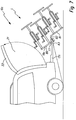
Die Lastenträger 10a, 10b weisen ein flexibles Erweiterungskonzept auf.The
Das Tragegestell 20 enthält einen Basis-Träger 44, dessen durch eine Tragplattform 53 bereitgestellte Ladekapazität durch Erweiterungsbauteile 45 vergrößert werden kann. Die Erweiterungsbauteile 45 sind beispielsweise Trägerstäbe 46, die nach hinten vor den Basisträger 44 vorstehen.The
Vor die Tragplattform 53 stehen ferner als Erweiterungsbauteile Tragelemente 58 vor, z.B. zum Abstellen der Fahrräder 23. Die Tragelemente 58 sind zweckmäßigerweise teleskopierbar und/oder bezüglich der Basis-Trägers 44 verschieblich, so dass sie bei Nichtgebrauch unter die Tragplattform 53 geschoben werden können.In front of the
Die Trägerstäbe 46 haben einen stufigen oder S-artigen Verlauf. Befestigungsabschnitte 47 der Trägerstäbe 46, die in der Fahrstellung F einen im Wesentlichen horizontalen Verlauf haben, sind an in Fahrzeuglängsrichtung verlaufenden Tragelementen 48 des Tragegestells 20 befestigt. Somit verlaufen die Befestigungsabschnitte 47 korrespondierend mit den Tragelementen 48. Die Befestigungsabschnitte 47 können z.B. seitlich an den Tragelementen 48 befestigt werden. Zur Befestigung können beispielsweise Sicherungssplinte, Bolzen oder dergleichen vorgesehen sein. Die Befestigungsabschnitte 47 können auch L-förmig oder U-förmig sein, so dass sie auf die Tragelemente 48 sozusagen aufgesattelt werden können und sich auf den Tragelementen 48 zumindest oberseitig abstützen.The
An die Befestigungsabschnitte 47 schließen sich Schrägabschnitte 49 der Trägerstäbe 46 an. Die Schrägabschnitte 49 verlaufen in der Fahrstellung F schräg weg vom Kraftfahrzeug 12 geneigt. An die Schrägabschnitte 49 schließen sich Tragabschnitte 50 der Trägerstäbe 46 an, die in der Fahrstellung F im Wesentlichen horizontal verlaufen. Auf den Tragabschnitten 50 können beispielsweise eine Tragplattform oder Last-Halterungen, z.B. Sportgerätehalter 24, befestigt werden.Adjacent to the
Die Tragabschnitte 50 oder daran angeordnete Sportgerätehalter 24 bilden vorzugsweise Betätigungshandhaben zum Verstellen der Trägeanordnung 19a von der Fahrstellung F in die Ladestellung L und/oder umgekehrt. Die Tragabschnitte 50 und/oder die Sportgerätehalter 24 kragen bezüglich der Schwenklager 30 verhältnismäßig weit aus und bilden somit Betätigungsarme oder Betätigungshebel, die eine leichte manuelle Betätigung der Trageanordnung 19a bei einem Verstellen von der Fahrstellung F in die Ladestellung L und umgekehrt ermöglichen. Die Bedienbarkeit des Lastenträgers 10b ist somit nicht eingeschränkt, auch wenn beispielsweise das Fuß-Betätigungsteil 37 durch die Erweiterung mit Hilfe der Erweiterungsbauteile 45 schwerer zugänglich ist.The supporting
Die Trageanordnung 19a kann mit einer Verriegelungseinrichtung 51 bezüglich der Tragstruktur 13a verriegelt werden. Die Verriegelungseinrichtung 51 enthält beispielsweise ein mit der Trageanordnung 19a fest verbundenes, jedoch bewegliches Verriegelungselement 52, beispielsweise eine Verriegelungsschraube oder einen Verriegelungsbolzen, das zum Verriegeln in eine Verriegelungsaufnahme 55 der Tragstruktur 19a eingreift.The
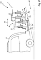
Die Trageanordnung 19a stellt mit den angebauten durch Erweiterungsbauteilen 45 eine untere Ladeebene 65 und eine obere Ladeebene 66 bereit. Somit ist unterhalb der oberen Ladeebene 66 ein Freiraum 67 zum Schwenken der Trageanordnung 19a in Richtung einer Fahrbahnoberfläche 69 vorhanden. Ferner lässt die obere Ladeebene 66 einen Blickbereich zu einer Heckleuchtenanordnung 70 frei, die am vom Kraftfahrzeug 12 abgewandten freien Ende der Tragstruktur 13 angeordnet ist. Die Heckleuchtenanordnung 70 enthält Heckleuchten 71, die mit einem Bordnetz 72 verbindbar sind, beispielsweise über eine Verbindung 73, bei der ein Stecker des Lastenträgers 10a in eine Steckdose des Kraftfahrzeuges 12 eingesteckt ist.The
Bei dem Lastenträger 10c ist eine stufige Trageanordnung 19c über eine Schwenklageranordnung 25c an einer Tragstruktur 13c schwenkbar gelagert. Die Tragstruktur 13c enthält beispielsweise Längsträger 14c, die in Aufnahmen am Heckbereich des Kraftfahrzeuges 12 eingesteckt sind und/oder beispielsweise an der Anhängekupplung 18 befestigt sind. Die Tragstruktur 13c stellt eine horizontale Tragebene bereit. Die Trageanordnung 19c ist treppenartig und stellt eine untere und eine obere Ladeebene 65, 66 bereit.In the
Auf jeder Ladeebene 65, 66 sind im einzelnen nicht dargestellte Halter, z.B. Sportgerätehalter für beispielsweise Fahrräder 23 fest, lösbar oder beweglich gehaltert. Beispielsweise stehen die unteren Fahrräder 23 auf einer unteren Plattform 74 während die auf der oberen Ladeebene 66 befindlichen Fahrräder 23 auf einer oberen Plattform 75 angeordnet sind. Das Wort "Plattform" ist hier in einem weiteren Sinne zu verstehen, d.h. es können zwar flächige Ablagen, z.B. Ablageplatten oder dergleichen, vorgesehen sein, oder aber beispielsweise auch Halterinnen für die Räder der Fahrräder 23 auf den beiden Ebenen 65, 66 vorgesehen sein.On each
Die Trageanordnung 19c enthält Gestell 85, das in der Art einer Wippe an der Tragstruktur 13c schwenkbar gelagert ist. Man kann das Gestell 85 daher auch als Wippe bezeichnen.The
Die Schwenklageranordnung 25c enthält zwei Schwenklager 83, die am freien Endbereich der Längsträger 14 bzw. der Tragstruktur 13c angeordnet sind. Die Schwenklager 76 definieren eine Schwenkachse 77, um die die Trageanordnung 19c zwischen einer Fahrstellung F und einer Ladestellung L schwenkt.The
Die Schwenkachse 77 verläuft horizontal. Die Schwenkachse 77 verläuft bezogen auf eine Fahrzeuglängsrichtung 78 des Kraftfahrzeuges 12 etwa in einer Längsmitte zwischen den beiden Plattformen 74 und 75. Beim Ausführungsbeispiel verläuft die Schwenkachse 77 etwa im Bereich der unteren Ladeebene 65. Es versteht sich, dass ein Verlauf durch beispielsweise die obere Ladeebene 66 durchaus denkbar ist, beispielsweise wenn ein L-förmig nach oben abstehender Abschnitt an der Tragstruktur 13c nach oben vorstehen würde. Die etwa längsmittige Anordnung der Schwenkachse 77 erleichtert ein Schwenken um die Schwenkachse 77, weil die auf den beiden Ladeebenen 65, 66 angeordneten Lasten 34 etwa dieselben Hebelarme und somit etwa ähnliche Kräfte auf die Trageanordnung 19c beidseits der Schwenkachse 77 ausüben.The
Zudem ist wegen der etwa längsmittigen Anordnung der Schwenkachse 77 der Schwenkwinkel, um den die Trageanordnung 19c zwischen der Fahrstellung F und Ladestellung L schwenkt, kleiner.In addition, because of the approximately longitudinal arrangement of the
Die Trageanordnung 19c enthält beispielsweise zwei seitliche Träger 79 mit in der Fahrstellung F horizontal verlaufenden, die Ladeebenen 65, 66 definierenden Tragabschnitten 80, 81, zwischen denen ein Verbindungsabschnitt 82 verläuft. Die Träger 79 sind beispielsweise Metallprofile oder dergleichen.The
Die Heckleuchtenanordnung 70c ist zweckmäßigerweise schwenkbar an der Trägerstruktur 13c angeordnet. Zum oder beim Schwenken der Trageanordnung 19c in die Ladestellung L wird die Heckleuchtenanordnung 70c beispielsweise nach unten geschwenkt. Dies wird beispielsweise dadurch bewirkt, dass der Verbindungsabschnitt 82 von oben her auf die Heckleuchtenanordnung 70c wirkt. Die Heckleuchtenanordnung 70c kann beispielsweise unter Federeinwirkung oder dergleichen wieder zurück nach oben in eine im wesentlichen senkrechte, der Fahrstellung F zugeordnete Fahrposition schwenken.The
Der Lastenträger 10d hat eine feststehenden, stufenförmige Trägerstruktur 84 mit einer unteren und einer oberen Ladeebene 65 und 66, die durch eine Tragstruktur 13d bereitgestellt werden. Von am Kraftfahrzeug 12 befestigen Längsträgern 14d stehen stufenförmig Träger 79d nach hinten oben vor. Die untere Ladeebene wird durch die Längsträgern 14d definiert, die obere Ladeebene 66 durch die Träger 79d bereitgestellt.The
Die Tragabschnitte 80, 81 sind im wesentlichen gleich lang, sodass sie auf den Ladeebenen 65, 66 bereitstehende Ladekapazität etwa gleich groß ist.The
Claims (15)
- Load carrier for a motor vehicle (12), in particular a car, with a support structure (13a, 13c) for carrying a load (34) which, in an operating position of the load carrier, extends to the rear beyond a rear section (11) of the motor vehicle (12), wherein it has a lower loading level (65) located closer to the vehicle tail end, and an upper loading level (66) further away from the vehicle tail end, wherein the support structure (13a, 13c) has at least one extension member (45), for increasing the loading capacity, which may be fitted releasably to a base carrier (44) or mounted movably thereon, characterised in that a taillight assembly (70; 70c) is mounted on the support structure, that the taillight assembly is located below the upper loading level (66), away from the rear free end of the load carrier and closer to the vehicle tail end, and that the upper loading level (66) is located above the lower loading level (65) in such a way that a view of the taillight assembly (70; 70c) remains free.
- Load carrier according to claim 1, characterised in that the lower and upper loading levels (65, 66) have substantially the same loading capacity and/or substantially the same length in the vehicle longitudinal direction (78), and/or that the lower and/or the upper loading level (65, 66) are stationary relative to the support structure.
- Load carrier according to claim 1 or 2, characterised in that the taillight assembly (70; 70c) is pivotable and/or that it has a carrier platform mounted in particular on the support assembly (19a) for setting down the load (34) and/or a sports equipment rack, in particular a cycle rack.
- Load carrier according to claim 1, characterised in that it has a support assembly (19a) for placing the load (34), adjustable relative to the support structure (13a, 13c), between a vehicle running position (F) provided for operation of the motor vehicle (12) and a loading position (L) provided for loading and unloading of the motor vehicle (12), wherein the support assembly (19a) with the load (34) mounted on it releases in the loading position (L) a swivelling section (21) of a tailgate (22) or a rear door of the motor vehicle (12).
- Load carrier according to claim 4, characterised in that the lower and/or the upper loading level (65, 66) are located on the support assembly and/or that, in the loading position (L), the support assembly (19a) adopts an inclined position facing away from the motor vehicle (12).
- Load carrier according to claim 4 or 5, characterised in that the support assembly is pivotably mounted on a swivel bearing assembly (25; 25c).
- Load carrier according to claim 6, characterised in that a swivel axis (77) of the swivel bearing assembly (25; 25c), in particular roughly horizontal, runs with reference to the vehicle longitudinal direction (78) of the motor vehicle between a longitudinal end section of the lower loading level (65) facing the vehicle tail end, and a free end section of the upper loading level (66) facing away from the vehicle tail end, wherein expediently the swivel axis (77) runs in the area of the lower loading level (65), and/or wherein expediently the swivel axis (77) runs approximately in the area of a longitudinal centre between the lower and the upper loading level (65, 66), and/or wherein expediently the swivel axis (77) runs through a swivel bearing of the swivel bearing assembly (25; 25c).
- Load carrier according to any of claims 6 or 7, characterised in that the swivel bearing assembly (25; 25c) comprises a multi-linkage arrangement (26a, 26b), in particular a four-bar linkage (27a, 27b), wherein the multi-linkage arrangement (26a, 26b) advantageously has a swivel arm (28) located away from the rear section (11) and a steering arm (29), in particular longer than the swivel arm (28), located closer to the rear section (11)..
- Load carrier according to any of claims 5 to 8, characterised in that the support assembly (19a) has, at least in the loaded state, a centre of gravity such that it remains automatically in the vehicle running position (F) and/or in the loading position (L), wherein the support assembly (19a), on an adjustment path between the vehicle running position (F) and the loading position (L), advantageously runs though a tipping point.
- Load carrier according to any of claims 4 to 9, characterised in that the support assembly (19a) is guided on the support structure (13a, 13c) with a linear traversing facility, and/or that the support assembly (19a), on an adjustment path between vehicle running position (F) and loading position (L), passes through a superimposed linear and swivel movement track.
- Load carrier according to any of the preceding claims, characterised in that it has a pedal-operated device (35) to shift the support assembly (19a) into the loading position (L) and/or the vehicle running position (F)., wherein the pedal-operated device (35) expediently includes a pedal element (36) which, in an operative position, lengthens an arm of the swivel bearing assembly (25) or is connected to the arm.
- Load carrier according to claim 11, characterised in that the pedal-operated device (35) advantageously has a clearance (41) so that it may be adjusted between a rest position (R) in which it is disengaged from the support assembly (19a), and an operating position (A) in which it is engaged with the support assembly (19a) for adjustment of the latter, wherein the pedal-operated device (35) expediently has an actuating element (37) connected to two components of the support assembly (19a) spaced apart in the vehicle transverse direction and/or of the swivel bearing assembly (25).
- Load carrier according to any claims 4 to 12, characterised in that it has a locking device (51) for locking the support assembly (19a) relative to the support structure (13a, 13c), at least in the vehicle running position (F) and/or in the loading position (L), and/or that that the support assembly (19a), at least in the vehicle running position (F), is located above or on the support structure (13a, 13c).
- Load carrier according to any of the preceding claims, characterised in that the upper loading level (66) is provided by the extension member or members (45) and/or that the extension member or members (45) have a step-shaped or S-like support bar (46) which may be attached releasably to the side of the base carrier (44) and/or that the extension member or members (45) has or have or forms or form an operating handle to shift the support assembly (19a) into the loading position (L) and/or the vehicle running position (F).
- Load carrier any of the preceding claims, characterised in that the support structure (13a, 13c) includes a carrier element mounted slidably on the motor vehicle (12), in particular a carrier platform which may be pulled out rearwards beyond the body (15) of the motor vehicle (12), and that the support structure (13a, 13c) has a mounting (16) for releasable fitting to a trailer coupling (18) of the motor vehicle (12).
Applications Claiming Priority (3)
| Application Number | Priority Date | Filing Date | Title |
|---|---|---|---|
| DE102007014618A DE102007014618A1 (en) | 2007-03-23 | 2007-03-23 | Load carrier i.e. bicycle rack, for motor vehicle i.e. passenger car, has carrying arrangement moved between driving position and loading position, and releasing pivoting region of rear flap or rear door of vehicle in loading position |
| DE102007015603.2A DE102007015603B4 (en) | 2007-03-29 | 2007-03-29 | Load carrier for a motor vehicle |
| EP08005282.2A EP1972500B2 (en) | 2007-03-23 | 2008-03-20 | Load carrier for a motor vehicle |
Related Parent Applications (3)
| Application Number | Title | Priority Date | Filing Date |
|---|---|---|---|
| EP08005282.2 Division | 2008-03-20 | ||
| EP08005282.2A Division EP1972500B2 (en) | 2007-03-23 | 2008-03-20 | Load carrier for a motor vehicle |
| EP08005282.2A Division-Into EP1972500B2 (en) | 2007-03-23 | 2008-03-20 | Load carrier for a motor vehicle |
Publications (3)
| Publication Number | Publication Date |
|---|---|
| EP2444286A2 EP2444286A2 (en) | 2012-04-25 |
| EP2444286A3 EP2444286A3 (en) | 2012-07-25 |
| EP2444286B1 true EP2444286B1 (en) | 2018-11-07 |
Family
ID=39400877
Family Applications (4)
| Application Number | Title | Priority Date | Filing Date |
|---|---|---|---|
| EP11004710.7A Revoked EP2364880B1 (en) | 2007-03-23 | 2008-03-20 | Load carrier for a motor vehicle |
| EP12000178.9A Revoked EP2444286B1 (en) | 2007-03-23 | 2008-03-20 | Load carrier for a motor vehicle |
| EP08005282.2A Active EP1972500B2 (en) | 2007-03-23 | 2008-03-20 | Load carrier for a motor vehicle |
| EP08005237.6A Active EP1972499B2 (en) | 2007-03-23 | 2008-03-20 | Load carrier for a motor vehicle |
Family Applications Before (1)
| Application Number | Title | Priority Date | Filing Date |
|---|---|---|---|
| EP11004710.7A Revoked EP2364880B1 (en) | 2007-03-23 | 2008-03-20 | Load carrier for a motor vehicle |
Family Applications After (2)
| Application Number | Title | Priority Date | Filing Date |
|---|---|---|---|
| EP08005282.2A Active EP1972500B2 (en) | 2007-03-23 | 2008-03-20 | Load carrier for a motor vehicle |
| EP08005237.6A Active EP1972499B2 (en) | 2007-03-23 | 2008-03-20 | Load carrier for a motor vehicle |
Country Status (2)
| Country | Link |
|---|---|
| EP (4) | EP2364880B1 (en) |
| AT (2) | ATE549209T1 (en) |
Families Citing this family (5)
| Publication number | Priority date | Publication date | Assignee | Title |
|---|---|---|---|---|
| DE102010045356A1 (en) | 2010-09-14 | 2012-03-15 | Westfalia-Automotive Gmbh | Load carrier with a swiveling sliding bearing |
| DE202013101224U1 (en) * | 2013-03-21 | 2013-05-06 | Guido Elting | Camping table |
| DK2848473T3 (en) | 2013-09-16 | 2016-06-06 | Carman Entpr Co Ltd | Lastbærer for mounting on a vehicle's rear end |
| CN104554047B (en) * | 2015-01-22 | 2016-06-29 | 宁波德坤工业设计有限公司 | A kind of afterbody carriage device of automobile |
| FR3057512B1 (en) * | 2016-10-13 | 2020-12-25 | Peugeot Citroen Automobiles Sa | RETRACTABLE BIKE HOLDER ON VEHICLE HITCH |
Citations (2)
| Publication number | Priority date | Publication date | Assignee | Title |
|---|---|---|---|---|
| US5527146A (en) | 1989-08-23 | 1996-06-18 | Softride, Inc. | Vehicle-mounted articulated support rack |
| US6129371A (en) | 1999-02-12 | 2000-10-10 | Powell; Richard A. | Dual level hitch |
Family Cites Families (26)
| Publication number | Priority date | Publication date | Assignee | Title |
|---|---|---|---|---|
| FR809094A (en) * | 1935-11-16 | 1937-02-23 | Improvements to luggage racks for motor vehicles | |
| US3757975A (en) † | 1972-01-12 | 1973-09-11 | C Sneider | Carrier frame for automobiles |
| DE4322016C2 (en) * | 1993-07-02 | 1996-10-17 | Cartec Gmbh Automobiltech | Trailer coupling-independent rear carrying device |
| US5460304A (en) * | 1993-10-05 | 1995-10-24 | Porter; Lawrence T. | Modular vehicular carrier system |
| US5664717A (en) † | 1995-11-13 | 1997-09-09 | Joder; Brian K. | Pivoting sports equipment carrier |
| US5730345A (en) | 1996-10-09 | 1998-03-24 | Acar Industries, Inc. | Bicycle rack |
| US5845832A (en) | 1997-09-18 | 1998-12-08 | Eichmann; Marty W. | Rear-mounted vehicle cargo carrier |
| US5881937A (en) * | 1997-10-14 | 1999-03-16 | Sadler; William R. | Movable frame assembly |
| US5853278A (en) † | 1997-11-25 | 1998-12-29 | Frantz; Charles G. | Cargo carrier |
| US6085954A (en) | 1998-07-15 | 2000-07-11 | Graber Products, Inc. | Pivoting extensible rear hitch attachment for equipment carrier |
| US6152341A (en) * | 1998-08-28 | 2000-11-28 | Outdoor Innovations, Inc. | Vehicle hitch mounted cargo carrier |
| DE69909256T2 (en) † | 1999-06-07 | 2004-05-27 | Scambia Industrial Developments Ag | Load carriers for fastening a load, in particular a bicycle and / or mopeds, to a motor vehicle |
| US6244483B1 (en) * | 1999-08-25 | 2001-06-12 | Mclemore John D. | Carrier device |
| US6401999B1 (en) | 1999-09-08 | 2002-06-11 | Kenneth L. Hehr | Hitch mounted carrier assembly |
| US20020005423A1 (en) * | 2000-05-17 | 2002-01-17 | Grover Donald D. | Hitch-mounted tilting cargo carrier |
| US6745926B2 (en) | 2000-08-10 | 2004-06-08 | Thule Sweden Ab | Securement arrangement for a hitch-mount carrier |
| CA2426975A1 (en) * | 2000-10-26 | 2002-05-07 | Reese Products, Inc. | Multipositional apparatus for mounting to a receiver assembly |
| DE10055994A1 (en) | 2000-11-11 | 2002-05-23 | Albert Schneider | Luggage carrier, swivel mounted to rear of car, comprising easy removable holding elements |
| NL1016761C1 (en) | 2000-11-30 | 2002-05-31 | Thomas Hendricus Petrus Jonk | Load carrier mountable at the rear of a motor vehicle, in particular for one or more bicycles. |
| DE10240463A1 (en) † | 2002-08-30 | 2004-03-11 | Al-Ko Kober Ag | Load carrier for attachment to a trailer hitch of a motor vehicle with load carrier adapter for a trailer drawbar |
| DE202004003423U1 (en) * | 2004-03-02 | 2004-05-13 | Reiss, Michael | Load carriers for motor vehicles |
| DE102004022835B4 (en) * | 2004-05-08 | 2013-10-17 | Audi Ag | Motor vehicle with a device for receiving objects |
| ES1057890Y (en) | 2004-06-23 | 2005-01-16 | Mesas Luis Saez | REAR CARRIER FOR VEHICLES. |
| SE0401817L (en) † | 2004-07-07 | 2005-11-22 | Thule Sweden Ab | Device for folding and folding down a load carrier attached to a vehicle |
| DE202005004043U1 (en) | 2005-03-10 | 2005-05-19 | Eufab Gmbh | Load carrier, in particular bicycle carrier |
| SE0500852L (en) * | 2005-04-15 | 2006-02-28 | Thule Sweden Ab | Device for a load carrier attached to a vehicle |
-
2008
- 2008-03-20 EP EP11004710.7A patent/EP2364880B1/en not_active Revoked
- 2008-03-20 AT AT08005282T patent/ATE549209T1/en active
- 2008-03-20 AT AT08005237T patent/ATE526202T1/en active
- 2008-03-20 EP EP12000178.9A patent/EP2444286B1/en not_active Revoked
- 2008-03-20 EP EP08005282.2A patent/EP1972500B2/en active Active
- 2008-03-20 EP EP08005237.6A patent/EP1972499B2/en active Active
Patent Citations (2)
| Publication number | Priority date | Publication date | Assignee | Title |
|---|---|---|---|---|
| US5527146A (en) | 1989-08-23 | 1996-06-18 | Softride, Inc. | Vehicle-mounted articulated support rack |
| US6129371A (en) | 1999-02-12 | 2000-10-10 | Powell; Richard A. | Dual level hitch |
Non-Patent Citations (2)
| Title |
|---|
| ANONYMOUS: "Der transportmanager mit system", ATERA-TRÄGERSYSTEME, 2006, pages 1 - 24, XP055629858 |
| ANONYMOUS: "DTS Wir machen ihnen das leben leichter", DTS, 2003 - 2004, pages 1 - 22, XP055629863 |
Also Published As
| Publication number | Publication date |
|---|---|
| EP1972500B1 (en) | 2012-03-14 |
| EP2364880B1 (en) | 2018-08-15 |
| EP1972499A3 (en) | 2010-02-10 |
| EP1972500A2 (en) | 2008-09-24 |
| EP1972499B1 (en) | 2011-09-28 |
| EP2364880A3 (en) | 2011-12-28 |
| EP1972499A2 (en) | 2008-09-24 |
| EP2444286A2 (en) | 2012-04-25 |
| ATE526202T1 (en) | 2011-10-15 |
| EP1972500B2 (en) | 2018-12-05 |
| EP2444286A3 (en) | 2012-07-25 |
| EP1972499B2 (en) | 2017-05-10 |
| ATE549209T1 (en) | 2012-03-15 |
| EP1972500A3 (en) | 2011-01-12 |
| EP2364880A2 (en) | 2011-09-14 |
Similar Documents
| Publication | Publication Date | Title |
|---|---|---|
| DE2420603C2 (en) | Mechanical changing system for attachable superstructures of trucks, trailers or semi-trailers | |
| EP0101054A2 (en) | Luggage carrier for vehicles, especially for caravans | |
| EP2444286B1 (en) | Load carrier for a motor vehicle | |
| EP2520465B1 (en) | Load carrier for a motor vehicle | |
| EP0210465A2 (en) | Protective device for a vehicle | |
| EP0254210B2 (en) | Nestable shopping trolley | |
| EP2428406B1 (en) | Load holder with a pivoting sliding bearing | |
| DE4241142A1 (en) | Device to fit rear load carrier to motor vehicle, esp. car | |
| DE102007015603B4 (en) | Load carrier for a motor vehicle | |
| DE102014110914B3 (en) | Transport trolley for transporting loads | |
| EP2594435B1 (en) | Transport device for a rear carrier of a motor vehicle | |
| DE102007014618A1 (en) | Load carrier i.e. bicycle rack, for motor vehicle i.e. passenger car, has carrying arrangement moved between driving position and loading position, and releasing pivoting region of rear flap or rear door of vehicle in loading position | |
| DE102006031885A1 (en) | Load e.g. bicycle, carrier e.g. load beam, for boot of motor vehicle, has load carrier unit arranged with respect to cross beam to form load surface, which is located behind another surface and viewed in normal vehicle traveling direction | |
| DE10061954A1 (en) | Storage system for transporting articles on back of vehicle comprises cross-bar forming integral part of rear bumper and which has apertures into which pins on hollow shelf fit | |
| EP3838710A1 (en) | Trolley for use as a bicycle trailer or as a hand trolley | |
| DE19621409C2 (en) | Lifting device for lifting or lowering a bicycle on or from a passenger car | |
| EP0133637A1 (en) | Front implement hitch device for a front covered vehicle for use in agriculture and/or the building industry, in particular for a farming tractor | |
| DE102023103476B4 (en) | Foldable transport device for bicycles | |
| DE3409405A1 (en) | TRANSPORT VEHICLE | |
| DE3801895A1 (en) | Device on the front end of a farm tractor for raising an additional weight carrier into a transportation position | |
| EP1405764A1 (en) | Load carrier, particularly a bicycle carrier | |
| DE19544574A1 (en) | Swing link suspension for wheel on wheelbarrow | |
| DE102019135040A1 (en) | Trolleys for use as a bicycle trailer or hand cart | |
| EP0035123A1 (en) | Stretcher support | |
| DE8225046U1 (en) | CAN BE CONNECTED TO A TRACTOR |
Legal Events
| Date | Code | Title | Description |
|---|---|---|---|
| AC | Divisional application: reference to earlier application |
Ref document number: 1972500 Country of ref document: EP Kind code of ref document: P |
|
| AK | Designated contracting states |
Kind code of ref document: A2 Designated state(s): AT BE BG CH CY CZ DE DK EE ES FI FR GB GR HR HU IE IS IT LI LT LU LV MC MT NL NO PL PT RO SE SI SK TR |
|
| PUAI | Public reference made under article 153(3) epc to a published international application that has entered the european phase |
Free format text: ORIGINAL CODE: 0009012 |
|
| RIN1 | Information on inventor provided before grant (corrected) |
Inventor name: HERMBUSCH, GERHARD Inventor name: WALDAU, JENS |
|
| PUAL | Search report despatched |
Free format text: ORIGINAL CODE: 0009013 |
|
| AK | Designated contracting states |
Kind code of ref document: A3 Designated state(s): AT BE BG CH CY CZ DE DK EE ES FI FR GB GR HR HU IE IS IT LI LT LU LV MC MT NL NO PL PT RO SE SI SK TR |
|
| RIC1 | Information provided on ipc code assigned before grant |
Ipc: B60R 9/06 20060101AFI20120621BHEP Ipc: B60R 9/10 20060101ALI20120621BHEP |
|
| 17P | Request for examination filed |
Effective date: 20130110 |
|
| GRAP | Despatch of communication of intention to grant a patent |
Free format text: ORIGINAL CODE: EPIDOSNIGR1 |
|
| STAA | Information on the status of an ep patent application or granted ep patent |
Free format text: STATUS: GRANT OF PATENT IS INTENDED |
|
| INTG | Intention to grant announced |
Effective date: 20180627 |
|
| GRAS | Grant fee paid |
Free format text: ORIGINAL CODE: EPIDOSNIGR3 |
|
| GRAA | (expected) grant |
Free format text: ORIGINAL CODE: 0009210 |
|
| STAA | Information on the status of an ep patent application or granted ep patent |
Free format text: STATUS: THE PATENT HAS BEEN GRANTED |
|
| AC | Divisional application: reference to earlier application |
Ref document number: 1972500 Country of ref document: EP Kind code of ref document: P |
|
| AK | Designated contracting states |
Kind code of ref document: B1 Designated state(s): AT BE BG CH CY CZ DE DK EE ES FI FR GB GR HR HU IE IS IT LI LT LU LV MC MT NL NO PL PT RO SE SI SK TR |
|
| REG | Reference to a national code |
Ref country code: GB Ref legal event code: FG4D Free format text: NOT ENGLISH |
|
| REG | Reference to a national code |
Ref country code: CH Ref legal event code: EP Ref country code: AT Ref legal event code: REF Ref document number: 1061667 Country of ref document: AT Kind code of ref document: T Effective date: 20181115 |
|
| REG | Reference to a national code |
Ref country code: IE Ref legal event code: FG4D Free format text: LANGUAGE OF EP DOCUMENT: GERMAN |
|
| REG | Reference to a national code |
Ref country code: DE Ref legal event code: R096 Ref document number: 502008016447 Country of ref document: DE |
|
| REG | Reference to a national code |
Ref country code: NL Ref legal event code: MP Effective date: 20181107 |
|
| REG | Reference to a national code |
Ref country code: LT Ref legal event code: MG4D |
|
| PG25 | Lapsed in a contracting state [announced via postgrant information from national office to epo] |
Ref country code: LT Free format text: LAPSE BECAUSE OF FAILURE TO SUBMIT A TRANSLATION OF THE DESCRIPTION OR TO PAY THE FEE WITHIN THE PRESCRIBED TIME-LIMIT Effective date: 20181107 Ref country code: NO Free format text: LAPSE BECAUSE OF FAILURE TO SUBMIT A TRANSLATION OF THE DESCRIPTION OR TO PAY THE FEE WITHIN THE PRESCRIBED TIME-LIMIT Effective date: 20190207 Ref country code: BG Free format text: LAPSE BECAUSE OF FAILURE TO SUBMIT A TRANSLATION OF THE DESCRIPTION OR TO PAY THE FEE WITHIN THE PRESCRIBED TIME-LIMIT Effective date: 20190207 Ref country code: FI Free format text: LAPSE BECAUSE OF FAILURE TO SUBMIT A TRANSLATION OF THE DESCRIPTION OR TO PAY THE FEE WITHIN THE PRESCRIBED TIME-LIMIT Effective date: 20181107 Ref country code: LV Free format text: LAPSE BECAUSE OF FAILURE TO SUBMIT A TRANSLATION OF THE DESCRIPTION OR TO PAY THE FEE WITHIN THE PRESCRIBED TIME-LIMIT Effective date: 20181107 Ref country code: HR Free format text: LAPSE BECAUSE OF FAILURE TO SUBMIT A TRANSLATION OF THE DESCRIPTION OR TO PAY THE FEE WITHIN THE PRESCRIBED TIME-LIMIT Effective date: 20181107 Ref country code: ES Free format text: LAPSE BECAUSE OF FAILURE TO SUBMIT A TRANSLATION OF THE DESCRIPTION OR TO PAY THE FEE WITHIN THE PRESCRIBED TIME-LIMIT Effective date: 20181107 Ref country code: IS Free format text: LAPSE BECAUSE OF FAILURE TO SUBMIT A TRANSLATION OF THE DESCRIPTION OR TO PAY THE FEE WITHIN THE PRESCRIBED TIME-LIMIT Effective date: 20190307 |
|
| PG25 | Lapsed in a contracting state [announced via postgrant information from national office to epo] |
Ref country code: GR Free format text: LAPSE BECAUSE OF FAILURE TO SUBMIT A TRANSLATION OF THE DESCRIPTION OR TO PAY THE FEE WITHIN THE PRESCRIBED TIME-LIMIT Effective date: 20190208 Ref country code: PT Free format text: LAPSE BECAUSE OF FAILURE TO SUBMIT A TRANSLATION OF THE DESCRIPTION OR TO PAY THE FEE WITHIN THE PRESCRIBED TIME-LIMIT Effective date: 20190307 Ref country code: SE Free format text: LAPSE BECAUSE OF FAILURE TO SUBMIT A TRANSLATION OF THE DESCRIPTION OR TO PAY THE FEE WITHIN THE PRESCRIBED TIME-LIMIT Effective date: 20181107 Ref country code: NL Free format text: LAPSE BECAUSE OF FAILURE TO SUBMIT A TRANSLATION OF THE DESCRIPTION OR TO PAY THE FEE WITHIN THE PRESCRIBED TIME-LIMIT Effective date: 20181107 |
|
| PG25 | Lapsed in a contracting state [announced via postgrant information from national office to epo] |
Ref country code: PL Free format text: LAPSE BECAUSE OF FAILURE TO SUBMIT A TRANSLATION OF THE DESCRIPTION OR TO PAY THE FEE WITHIN THE PRESCRIBED TIME-LIMIT Effective date: 20181107 Ref country code: DK Free format text: LAPSE BECAUSE OF FAILURE TO SUBMIT A TRANSLATION OF THE DESCRIPTION OR TO PAY THE FEE WITHIN THE PRESCRIBED TIME-LIMIT Effective date: 20181107 Ref country code: IT Free format text: LAPSE BECAUSE OF FAILURE TO SUBMIT A TRANSLATION OF THE DESCRIPTION OR TO PAY THE FEE WITHIN THE PRESCRIBED TIME-LIMIT Effective date: 20181107 Ref country code: CZ Free format text: LAPSE BECAUSE OF FAILURE TO SUBMIT A TRANSLATION OF THE DESCRIPTION OR TO PAY THE FEE WITHIN THE PRESCRIBED TIME-LIMIT Effective date: 20181107 |
|
| REG | Reference to a national code |
Ref country code: DE Ref legal event code: R026 Ref document number: 502008016447 Country of ref document: DE |
|
| PLBI | Opposition filed |
Free format text: ORIGINAL CODE: 0009260 |
|
| PLAX | Notice of opposition and request to file observation + time limit sent |
Free format text: ORIGINAL CODE: EPIDOSNOBS2 |
|
| PG25 | Lapsed in a contracting state [announced via postgrant information from national office to epo] |
Ref country code: SK Free format text: LAPSE BECAUSE OF FAILURE TO SUBMIT A TRANSLATION OF THE DESCRIPTION OR TO PAY THE FEE WITHIN THE PRESCRIBED TIME-LIMIT Effective date: 20181107 Ref country code: RO Free format text: LAPSE BECAUSE OF FAILURE TO SUBMIT A TRANSLATION OF THE DESCRIPTION OR TO PAY THE FEE WITHIN THE PRESCRIBED TIME-LIMIT Effective date: 20181107 Ref country code: EE Free format text: LAPSE BECAUSE OF FAILURE TO SUBMIT A TRANSLATION OF THE DESCRIPTION OR TO PAY THE FEE WITHIN THE PRESCRIBED TIME-LIMIT Effective date: 20181107 |
|
| 26 | Opposition filed |
Opponent name: ATERA GMBH Effective date: 20190731 |
|
| PG25 | Lapsed in a contracting state [announced via postgrant information from national office to epo] |
Ref country code: MC Free format text: LAPSE BECAUSE OF FAILURE TO SUBMIT A TRANSLATION OF THE DESCRIPTION OR TO PAY THE FEE WITHIN THE PRESCRIBED TIME-LIMIT Effective date: 20181107 Ref country code: SI Free format text: LAPSE BECAUSE OF FAILURE TO SUBMIT A TRANSLATION OF THE DESCRIPTION OR TO PAY THE FEE WITHIN THE PRESCRIBED TIME-LIMIT Effective date: 20181107 |
|
| REG | Reference to a national code |
Ref country code: CH Ref legal event code: PL |
|
| GBPC | Gb: european patent ceased through non-payment of renewal fee |
Effective date: 20190320 |
|
| PG25 | Lapsed in a contracting state [announced via postgrant information from national office to epo] |
Ref country code: LU Free format text: LAPSE BECAUSE OF NON-PAYMENT OF DUE FEES Effective date: 20190320 |
|
| REG | Reference to a national code |
Ref country code: BE Ref legal event code: MM Effective date: 20190331 |
|
| PLBB | Reply of patent proprietor to notice(s) of opposition received |
Free format text: ORIGINAL CODE: EPIDOSNOBS3 |
|
| PG25 | Lapsed in a contracting state [announced via postgrant information from national office to epo] |
Ref country code: IE Free format text: LAPSE BECAUSE OF NON-PAYMENT OF DUE FEES Effective date: 20190320 Ref country code: GB Free format text: LAPSE BECAUSE OF NON-PAYMENT OF DUE FEES Effective date: 20190320 Ref country code: CH Free format text: LAPSE BECAUSE OF NON-PAYMENT OF DUE FEES Effective date: 20190331 Ref country code: LI Free format text: LAPSE BECAUSE OF NON-PAYMENT OF DUE FEES Effective date: 20190331 |
|
| PG25 | Lapsed in a contracting state [announced via postgrant information from national office to epo] |
Ref country code: BE Free format text: LAPSE BECAUSE OF NON-PAYMENT OF DUE FEES Effective date: 20190331 |
|
| PG25 | Lapsed in a contracting state [announced via postgrant information from national office to epo] |
Ref country code: TR Free format text: LAPSE BECAUSE OF FAILURE TO SUBMIT A TRANSLATION OF THE DESCRIPTION OR TO PAY THE FEE WITHIN THE PRESCRIBED TIME-LIMIT Effective date: 20181107 |
|
| PG25 | Lapsed in a contracting state [announced via postgrant information from national office to epo] |
Ref country code: MT Free format text: LAPSE BECAUSE OF FAILURE TO SUBMIT A TRANSLATION OF THE DESCRIPTION OR TO PAY THE FEE WITHIN THE PRESCRIBED TIME-LIMIT Effective date: 20181107 |
|
| REG | Reference to a national code |
Ref country code: AT Ref legal event code: MM01 Ref document number: 1061667 Country of ref document: AT Kind code of ref document: T Effective date: 20190320 |
|
| PG25 | Lapsed in a contracting state [announced via postgrant information from national office to epo] |
Ref country code: AT Free format text: LAPSE BECAUSE OF NON-PAYMENT OF DUE FEES Effective date: 20190320 |
|
| PG25 | Lapsed in a contracting state [announced via postgrant information from national office to epo] |
Ref country code: CY Free format text: LAPSE BECAUSE OF FAILURE TO SUBMIT A TRANSLATION OF THE DESCRIPTION OR TO PAY THE FEE WITHIN THE PRESCRIBED TIME-LIMIT Effective date: 20181107 |
|
| APAH | Appeal reference modified |
Free format text: ORIGINAL CODE: EPIDOSCREFNO |
|
| APBM | Appeal reference recorded |
Free format text: ORIGINAL CODE: EPIDOSNREFNO |
|
| APBP | Date of receipt of notice of appeal recorded |
Free format text: ORIGINAL CODE: EPIDOSNNOA2O |
|
| APBM | Appeal reference recorded |
Free format text: ORIGINAL CODE: EPIDOSNREFNO |
|
| APBP | Date of receipt of notice of appeal recorded |
Free format text: ORIGINAL CODE: EPIDOSNNOA2O |
|
| PG25 | Lapsed in a contracting state [announced via postgrant information from national office to epo] |
Ref country code: HU Free format text: LAPSE BECAUSE OF FAILURE TO SUBMIT A TRANSLATION OF THE DESCRIPTION OR TO PAY THE FEE WITHIN THE PRESCRIBED TIME-LIMIT; INVALID AB INITIO Effective date: 20080320 |
|
| APBQ | Date of receipt of statement of grounds of appeal recorded |
Free format text: ORIGINAL CODE: EPIDOSNNOA3O |
|
| APBQ | Date of receipt of statement of grounds of appeal recorded |
Free format text: ORIGINAL CODE: EPIDOSNNOA3O |
|
| PGFP | Annual fee paid to national office [announced via postgrant information from national office to epo] |
Ref country code: DE Payment date: 20220309 Year of fee payment: 15 |
|
| PGFP | Annual fee paid to national office [announced via postgrant information from national office to epo] |
Ref country code: FR Payment date: 20220203 Year of fee payment: 15 |
|
| REG | Reference to a national code |
Ref country code: DE Ref legal event code: R103 Ref document number: 502008016447 Country of ref document: DE Ref country code: DE Ref legal event code: R064 Ref document number: 502008016447 Country of ref document: DE |
|
| APBU | Appeal procedure closed |
Free format text: ORIGINAL CODE: EPIDOSNNOA9O |
|
| RDAF | Communication despatched that patent is revoked |
Free format text: ORIGINAL CODE: EPIDOSNREV1 |
|
| STAA | Information on the status of an ep patent application or granted ep patent |
Free format text: STATUS: PATENT REVOKED |
|
| RDAG | Patent revoked |
Free format text: ORIGINAL CODE: 0009271 |
|
| REG | Reference to a national code |
Ref country code: CH Ref legal event code: PL |
|
| 27W | Patent revoked |
Effective date: 20230124 |
|
| REG | Reference to a national code |
Ref country code: AT Ref legal event code: MA03 Ref document number: 1061667 Country of ref document: AT Kind code of ref document: T Effective date: 20230124 |