EP2441985A2 - Ölzufuhrsystem für Automatikgetriebe - Google Patents
Ölzufuhrsystem für Automatikgetriebe Download PDFInfo
- Publication number
- EP2441985A2 EP2441985A2 EP20100192873 EP10192873A EP2441985A2 EP 2441985 A2 EP2441985 A2 EP 2441985A2 EP 20100192873 EP20100192873 EP 20100192873 EP 10192873 A EP10192873 A EP 10192873A EP 2441985 A2 EP2441985 A2 EP 2441985A2
- Authority
- EP
- European Patent Office
- Prior art keywords
- oil
- pressure
- pressure part
- low
- oil pump
- Prior art date
- Legal status (The legal status is an assumption and is not a legal conclusion. Google has not performed a legal analysis and makes no representation as to the accuracy of the status listed.)
- Granted
Links
- 230000005540 biological transmission Effects 0.000 title claims abstract description 47
- 230000001105 regulatory effect Effects 0.000 claims abstract description 41
- 230000001276 controlling effect Effects 0.000 claims abstract description 11
- 238000005086 pumping Methods 0.000 claims abstract description 4
- 230000003134 recirculating effect Effects 0.000 claims description 6
- 239000000446 fuel Substances 0.000 abstract description 8
- 238000007599 discharging Methods 0.000 abstract description 2
- 239000003921 oil Substances 0.000 description 206
- 238000001816 cooling Methods 0.000 description 7
- 230000001050 lubricating effect Effects 0.000 description 7
- 230000003247 decreasing effect Effects 0.000 description 3
- 238000010586 diagram Methods 0.000 description 3
- 238000012986 modification Methods 0.000 description 3
- 230000004048 modification Effects 0.000 description 3
- 230000033228 biological regulation Effects 0.000 description 1
- 230000007423 decrease Effects 0.000 description 1
- 238000005516 engineering process Methods 0.000 description 1
- 238000000034 method Methods 0.000 description 1
Images
Classifications
-
- F—MECHANICAL ENGINEERING; LIGHTING; HEATING; WEAPONS; BLASTING
- F16—ENGINEERING ELEMENTS AND UNITS; GENERAL MEASURES FOR PRODUCING AND MAINTAINING EFFECTIVE FUNCTIONING OF MACHINES OR INSTALLATIONS; THERMAL INSULATION IN GENERAL
- F16H—GEARING
- F16H61/00—Control functions within control units of change-speed- or reversing-gearings for conveying rotary motion ; Control of exclusively fluid gearing, friction gearing, gearings with endless flexible members or other particular types of gearing
- F16H61/0021—Generation or control of line pressure
- F16H61/0025—Supply of control fluid; Pumps therefor
- F16H61/0031—Supply of control fluid; Pumps therefor using auxiliary pumps, e.g. pump driven by a different power source than the engine
-
- F—MECHANICAL ENGINEERING; LIGHTING; HEATING; WEAPONS; BLASTING
- F16—ENGINEERING ELEMENTS AND UNITS; GENERAL MEASURES FOR PRODUCING AND MAINTAINING EFFECTIVE FUNCTIONING OF MACHINES OR INSTALLATIONS; THERMAL INSULATION IN GENERAL
- F16H—GEARING
- F16H61/00—Control functions within control units of change-speed- or reversing-gearings for conveying rotary motion ; Control of exclusively fluid gearing, friction gearing, gearings with endless flexible members or other particular types of gearing
- F16H61/0021—Generation or control of line pressure
- F16H61/0025—Supply of control fluid; Pumps therefor
-
- F—MECHANICAL ENGINEERING; LIGHTING; HEATING; WEAPONS; BLASTING
- F16—ENGINEERING ELEMENTS AND UNITS; GENERAL MEASURES FOR PRODUCING AND MAINTAINING EFFECTIVE FUNCTIONING OF MACHINES OR INSTALLATIONS; THERMAL INSULATION IN GENERAL
- F16H—GEARING
- F16H61/00—Control functions within control units of change-speed- or reversing-gearings for conveying rotary motion ; Control of exclusively fluid gearing, friction gearing, gearings with endless flexible members or other particular types of gearing
- F16H61/0021—Generation or control of line pressure
- F16H2061/0037—Generation or control of line pressure characterised by controlled fluid supply to lubrication circuits of the gearing
-
- Y—GENERAL TAGGING OF NEW TECHNOLOGICAL DEVELOPMENTS; GENERAL TAGGING OF CROSS-SECTIONAL TECHNOLOGIES SPANNING OVER SEVERAL SECTIONS OF THE IPC; TECHNICAL SUBJECTS COVERED BY FORMER USPC CROSS-REFERENCE ART COLLECTIONS [XRACs] AND DIGESTS
- Y10—TECHNICAL SUBJECTS COVERED BY FORMER USPC
- Y10T—TECHNICAL SUBJECTS COVERED BY FORMER US CLASSIFICATION
- Y10T137/00—Fluid handling
- Y10T137/8593—Systems
- Y10T137/85978—With pump
- Y10T137/85986—Pumped fluid control
Definitions
- the present invention relates to an oil supply system of an automatic transmission, and more particularly, to an oil supply system of an automatic transmission that supply oil from an oil reservoir to a high-pressure part for operating a clutch and to a low-pressure part for cooling and lubricating, using an oil pump.
- Improving power transmission efficiency the transmission is necessary to improve fuel efficiency in automatic transmission vehicles, but the oil pump in the automatic transmission is a part reducing the power transmission efficiency, such that the power transmission efficiency of the transmission can be considerably increased, if unnecessary power consumption of the oil pump can be reduced.
- the output flow rate of the oil pump is composed of the flow rate of the high-pressure part for operating the clutch, the flow rate of the low-pressure part for cooling and lubricating, and the recirculation flow rate retuning the flow rate left after generating desired oil pressure from a regulating valve to the inlet of the oil pump, however, the oil supply systems discharges the entire oil on the basis of the high-pressure part used to control the clutch in the related art, such that the oil pump consumes a large amount of power and accordingly the power transmission efficiency of transmissions is reduced.
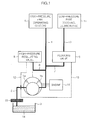
- an inlet 1a of an oil pump 1 is connected with an oil reservoir 3 through an oil supply channel 2
- an outlet 1b of oil pump 1 is connected to a high-pressure part 5 for operating a clutch through a high-pressure part channel 4
- high-pressure channel 4 is connected with a high-pressure regulating valve 8 and a reducing valve 9 through a first valve channel 6 and a second valve channel 7, respectively
- reducing valve 9 is connected to a low-pressure part 11 for cooling and lubricating through a low-pressure part channel 10
- high-pressure regulating valve 8 and reducing valve 9 are connected with oil supply channel 2 through a first return channel 12 and a second return channel 13, respectively.
- oil 14 in oil reservoir 3 is supplied to inlet 1a of oil pump 1 through oil filter 15 and oil pump 1 is operated by power from an engine 16.
- oil pump 1 is operated by the power from engine 16
- oil 14 in oil reservoir 3 flows into inlet 1a and the oil discharged from outlet 1b to high-pressure part channel 4 is controlled at high pressure by high-pressure regulating valve 8 and supplied to high-pressure part 5.
- reducing valve 9 reduces high pressure of the oil to low pressure, and the oil at the low pressure reduced by reducing valve 9 is supplied to low-pressure part 11.
- the oil left from the oil increased in pressure by high-pressure regulating valve 8 recirculates to inlet 1a of oil pump 1 through first return channel 12 and oil supply channel 2 and the oil left from the oil decreased in pressure by reducing valve 9 recirculates to inlet 1a of oil pump 1 through second return channel 13 and oil supply channel 2.
- low-pressure part 11 is used to cooling and lubricating the transmission, it needs a lot of flow rate, while since high-pressure part 5 is used to control the clutch, it needs a smaller amount of flow rate than low-pressure part 11.
- oil pump 1 discharges the entire flow rate on the basis of high-pressure part 5, such that oil pump 1 requires a large amount power.
- high-pressure part 5 requires pressure of 20kgf/cm 2 and flow rate of 51pm
- low-pressure part 11 requires pressure of 8kgf/cm 2 and flow rate 101pm
- the recirculation flow rate is 151pm
- the consuming power 980W of oil pump 1 is relatively large and the large consuming power of oil pump 1, as described above, considerably reduces the power transmission efficiency of the transmission, such that the fuel efficiency of the vehicle reduces. Further, excessive load is applied to oil pump 1, such that durability of oil pump 1 is reduced and large noise is caused. Pressure vibration is excessively generated by cavitation when oil pump 1 operates at high speed.
- the present invention has been made in an effort to provide an oil supply system of an automatic transmission that has an improved configuration by making the oil pump discharge the entire flow rate on the basis of a low-pressure part for cooling and lubricating and controlling the pressure of only some of the oil for a high-pressure part at high pressure and then supplying the oil to the high-pressure part, to reduce a large amount of power consumed by the oil pump, improves fuel efficiency by largely improving power transmission efficiency of the transmission, and improves durability and reduces noise and pressure vibration by reducing the load applied to the oil pump.
- One aspect of the present invention provides an oil supply system of an automatic transmission which supplies oil from an oil reservoir to a high-pressure part and a low-pressure part, using an oil pump, and includes a first oil pump pumping up oil from the oil reservoir and supplying the oil to the low-pressure part, a low-pressure regulating valve connected to a low-pressure part channel connecting the first oil pump with the low-pressure part, and controlling the pressure of the oil discharged from the first oil pump at pressure required by the low-pressure part, a second oil pump receiving the oil of which the pressure is controlled through the low-pressure regulating valve and supplying the oil to the high-pressure part, and a high-pressure regulating valve connected to a high-pressure part channel connecting the second oil pump with the high-pressure part and controlling the pressure of the oil discharged from the second oil pump at pressure required by the high-pressure part.
- the oil supply system of an automatic transmission further includes a first return channel recirculating the oil left after generating the low-pressure oil through the low-pressure regulating valve to the inlet of the first oil pump, a second return channel recirculating the oil left after generating the high-pressure oil through the high-pressure regulating valve to the inlet of the second oil pump, a connection channel connecting the low-pressure part channel with the high-pressure part channel, and a one-way check valve allowing for oil flow from the low-pressure part channel to the high-pressure part channel and preventing oil flow in the opposite direction.
- Another aspect of the present invention provides an oil supply system of an automatic transmission which supplies oil from an oil reservoir to a high-pressure part and a low-pressure part, using an oil pump, and includes a first oil pump pumping up oil from the oil reservoir and supplying the oil to the low-pressure part, a low-pressure regulating valve connected to a low-pressure part channel connecting the first oil pump with the low-pressure part, and controlling the pressure of the oil discharged from the first oil pump at pressure required by the low-pressure part, a second oil pump receiving the oil of which the pressure is controlled through the low-pressure regulating valve and supplying the oil to the high-pressure part, a high-pressure regulating valve connected to a high-pressure part channel connecting the second oil pump with the high-pressure part and controlling the pressure of the oil discharged from the second oil pump at pressure required by the high-pressure part, a first return channel recirculating the oil left after generating the low-pressure oil through the low-pressure regulating valve to the inlet of the first oil pump, and a second return channel recirculating
- the oil supply system of an automatic transmission further includes a connection channel connecting the low-pressure part channel with the high-pressure part channel, and a one-way check valve disposed in the connection channel to allow for oil flow from the low-pressure part channel to the high-pressure part channel and prevent oil flow in the opposite direction.
- an oil supply system of an automatic transmission can remarkably reduce the total consuming power of oil pumps, by discharging the entire oil on the basis of a low-pressure part and controlling only some of the oil, which is required by a high-pressure part, at high pressure, and then supplying the oil to high-pressure part, can considerably improve power transmission efficiency of the transmission, and can improve fuel efficiency and durability of the oil pumps and reduce loss of power, noise, and pressure vibration.
- FIG. 1 is a diagram illustrating an oil supply system of an automatic transmission of the related art.
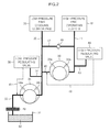
- FIG. 2 is a diagram illustrating an exemplary oil supply system of an automatic transmission according to the present invention.
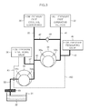
- FIG. 3 is a diagram illustrating an exemplary oil supply system of an automatic transmission according to the present invention.
- FIG. 2 shows an oil supply system according to various embodiments of the present invention, where oil 32 is stored in an oil reservoir 31, oil reservoir 31 is connected with an inlet 34a of a first oil pump 34 through an oil supply channel 33, outlet 34b of first oil pump 34 is connected to a low-pressure part 36 for cooling and lubricating through a low-pressure part channel 35, a low-pressure regulating valve 38 is connected to low-pressure part channel 35 through a first valve channel 37, such that low-pressure regulating valve 38 controls the pressure of oil discharged to low-pressure part channel 35 from outlet 34b of first oil pump 34 at a level required by low-pressure part 36.
- a sub-channel 40 diverging from low-pressure part channel 35 to supply the oil of which the pressure is controlled through low-pressure regulating valve 38 to a second oil pump 39 is connected with inlet 39a of second oil pump 39, an outlet 39b of second oil pump 39 is connected to a high-pressure part 42 for operating a clutch through a high-pressure part channel 41, and a high-pressure regulating valve 44 is connected to high-pressure part channel 41 through a second valve channel 43, such that high-pressure regulating valve 44 controls the pressure of the oils discharged to high-pressure channel 41 from outlet 39b of second oil pump 39 at a level (high pressure) required by high-pressure part 42.
- the oil supply system includes a first return channel 45 connecting an oil intake channel 33 with low-pressure regulating valve 38 to recirculate the oil left after generating the low-pressure oil through low-pressure regulating valve 38 to inlet 34a of first oil pump 34, and a second return channel 46 connecting sub-channel 40 with high-pressure regulating valve 44 to recirculate the oil left after generating the high-pressure oil through high-pressure regulating valve to inlet 39a of second oil pump 39.
- the oil supply system further includes a connection channel 47 that connects low-pressure part channel 35 with high-pressure part channel 41, and a one-way check valve 48 that allows for oil flow from low-pressure part channel 35 to high-pressure part channel 41 and prevents oil flow in the opposite direction is disposed in connecting channel 47.
- connecting channel 47 is connected with the line between low-pressure regulating valve 38 and low-pressure part 36 in low-pressure part channel 35, while the other end is connected with the line between high-pressure regulating valve 44 and high-pressure part 42 in high-pressure part channel 41.
- one-way check valve 48 is a valve opening connection channel 47, only when the oil pressure of high-pressure part channel 41 is lower than the oil pressure of low-pressure part channel 35.
- the pressure of the high-pressure part may need to be lower than the pressure of the low-pressure part while the vehicle travels under small load, in which second oil pump 39 stops and the oil is supplied from low-pressure part 35 to high-pressure part 42 through connection channel 47 and high-pressure part channel 41 by one-way check valve 48.
- the high-pressure part 42 requires high-pressure oil, because large load is applied thereto, in which second oil pump 39 and high-pressure regulating valve 44 operate.
- the oil pressure of high-pressure part channel 41 increases larger than the oil pressure of low-pressure part channel 35, such that one-way check valve 48 is kept closed. Therefore, the connection channel 47 connecting low-pressure part channel 35 with high-pressure part channel 41 is closed by one-way check valve 48, and low-pressure oil and high pressure oil start to be supplied to low-pressure part 36 and high-pressure part 42, respectively.
- the low-pressure part oil is supplied through one-way check valve 48 in a failsafe condition in which second oil pump 39 fails to normally operate, thereby implementing emergency operation.
- both of first oil pump 34 and second oil pump 39 may be mechanical oil pumps that are operated by power from an engine.
- first oil pump 34 may be a mechanical oil pump that is operated by the power from an engine and second oil pump 39 may be an electric oil pump that is operated by power from an electric motor.
- the electric motor is operated by electric signals from an oil pump control unit, and the parameters that are inputted to the oil pump control unit to control the operation of the electric motor may be the number of revolution (rpm) of the engine, engine torque, vehicle speed, shifting, oil temperature etc.
- both of first oil pump 34 and second oil pump 39 may be electric oil pumps that are operated by power from an electric motor.
- Oil 32 in oil reservoir 31 flows into inlet 34a of first oil pump 34 through an oil filter 49 by the operation of first oil pump 34.
- the oil discharged to low-pressure part channel 35 through outlet 34b of first oil pump 34 decreases in pressure by low-pressure regulating valve 38 and then supplied to low-pressure part 36.
- the oil left after generating the low-pressure oil through low-pressure regulating valve 38 recirculates to inlet 34a of first oil pump 34 through first return channel 45 and oil supply channel 33.
- low-pressure oil generated through low-pressure regulating valve 38 is supplied to inlet 39a of second oil pump 39 through sub-channel 40 while the low-pressure oil discharged to high-pressure part channel 41 through outlet 39b of second oil pump 39 is controlled at the pressure (high pressure) required by high-pressure part 42 by high-pressure regulating valve 44 and then supplied to high-pressure part 42.
- oil left after generating the high-pressure oil through high-pressure regulating valve 44 recirculates to inlet 39a of second oil pump 39 through second return channel 46 and sub- channel 40.
- low-pressure part 36 is used to cooling and lubricating the transmission, it needs a lot of flow rate, while since high-pressure part 42 is used to control the clutch, it needs a smaller amount of flow rate than low-pressure part 36.
- the factors reducing power transmission efficiency of a transmission is considerably decreased, such that the power transmission efficiency of the transmission is largely improved and the fuel efficiency can be further improved.
- the load exerted in the oil pumps can be decreased, such that it is possible to improve durability of the oil pumps and reduce noise and pressure vibration.
- FIG. 3 shows an oil supply system according to various embodiments of the present invention. Comparing the configuration shown in FIG. 3 with the configuration shown in FIG. 2 , it is different that a second return channel 460 is connected to an oil supply channel 33 to recirculate the oil left after generating high-pressure oil through a high-pressure regulating valve 44 to an inlet 34a of a first oil pump 34, and the others are all the same as those shown in FIG. 2 .
- the entire oil is discharged on the basis of a low-pressure part 36 and only some of the oil which is required by a high-pressure part 42 is controlled at high pressure and then supplied to high-pressure part 42, as in that shown in FIG. 2 . Accordingly, the total consuming power of the oil pumps can be considerably reduced, as compared with the configuration of the related art shown in FIG. 1 , and the detailed description is not provided.
Landscapes
- Engineering & Computer Science (AREA)
- General Engineering & Computer Science (AREA)
- Mechanical Engineering (AREA)
- Control Of Transmission Device (AREA)
Applications Claiming Priority (1)
| Application Number | Priority Date | Filing Date | Title |
|---|---|---|---|
| KR1020100099188A KR20120037623A (ko) | 2010-10-12 | 2010-10-12 | 변속기의 오일공급시스템 |
Publications (3)
| Publication Number | Publication Date |
|---|---|
| EP2441985A2 true EP2441985A2 (de) | 2012-04-18 |
| EP2441985A3 EP2441985A3 (de) | 2012-07-04 |
| EP2441985B1 EP2441985B1 (de) | 2013-07-31 |
Family
ID=45098763
Family Applications (1)
| Application Number | Title | Priority Date | Filing Date |
|---|---|---|---|
| EP20100192873 Not-in-force EP2441985B1 (de) | 2010-10-12 | 2010-11-29 | Ölzufuhrsystem für Automatikgetriebe |
Country Status (5)
| Country | Link |
|---|---|
| US (1) | US8512008B2 (de) |
| EP (1) | EP2441985B1 (de) |
| JP (1) | JP5558316B2 (de) |
| KR (1) | KR20120037623A (de) |
| CN (1) | CN102444679B (de) |
Cited By (6)
| Publication number | Priority date | Publication date | Assignee | Title |
|---|---|---|---|---|
| EP2716912A1 (de) | 2012-10-08 | 2014-04-09 | Magna International Japan Inc. | Doppelpumpe mit Druckgleichgewicht |
| EP2933491A4 (de) * | 2012-12-17 | 2016-08-31 | Tbk Co Ltd | Flüssigkeitszuführvorrichtung |
| EP3021010A4 (de) * | 2013-07-10 | 2017-09-13 | Kawasaki Jukogyo Kabushiki Kaisha | Hydraulische schaltung zur steuerung eines stufenlosen getriebes |
| DE102013113342B4 (de) * | 2013-04-02 | 2021-06-10 | Hyundai Motor Company | Hydraulikdruckzuführsystem eines Automatikgetriebes für ein Fahrzeug |
| EP3936235A1 (de) * | 2020-07-10 | 2022-01-12 | Wagner International Ag | Beschichtungsanlage zum beschichten von werkstücken mit beschichtungsmaterial |
| DE102013112689B4 (de) | 2013-04-02 | 2023-07-27 | Hyundai Motor Company | Hydraulikdruckzuführsystem eines Automatikgetriebes |
Families Citing this family (35)
| Publication number | Priority date | Publication date | Assignee | Title |
|---|---|---|---|---|
| US9121460B2 (en) * | 2012-03-23 | 2015-09-01 | GM Global Technology Operations LLC | Transmission control fluid diffuser |
| KR20140032033A (ko) * | 2012-09-03 | 2014-03-14 | 현대자동차주식회사 | 차량용 자동변속기의 유압공급시스템 |
| KR101394039B1 (ko) * | 2012-09-03 | 2014-05-12 | 현대자동차 주식회사 | 차량용 자동변속기의 유압공급시스템 |
| KR101865716B1 (ko) * | 2012-09-03 | 2018-06-11 | 현대자동차 주식회사 | 차량용 자동변속기의 유압공급시스템 |
| KR101338454B1 (ko) * | 2012-09-03 | 2013-12-10 | 현대자동차주식회사 | 차량용 자동변속기의 유압공급시스템 |
| KR101394038B1 (ko) * | 2012-09-03 | 2014-05-12 | 현대자동차 주식회사 | 차량용 자동변속기의 유압공급시스템 |
| KR101338455B1 (ko) | 2012-09-03 | 2013-12-10 | 현대자동차주식회사 | 차량용 자동변속기의 유압공급시스템 |
| KR101394040B1 (ko) * | 2012-09-03 | 2014-05-12 | 현대자동차 주식회사 | 차량용 자동변속기의 유압공급시스템 |
| KR101326850B1 (ko) * | 2012-10-04 | 2013-11-11 | 기아자동차주식회사 | 오일펌프 제어 시스템 및 방법 |
| KR101405192B1 (ko) * | 2012-11-05 | 2014-06-10 | 현대자동차 주식회사 | 차량용 자동변속기의 유압공급시스템 |
| KR101405207B1 (ko) * | 2012-11-06 | 2014-06-10 | 현대자동차 주식회사 | 차량용 자동변속기의 유압공급시스템 |
| KR101438607B1 (ko) * | 2012-12-12 | 2014-09-05 | 현대자동차 주식회사 | 차량용 자동변속기의 유압공급시스템 |
| JP5956672B2 (ja) * | 2013-02-26 | 2016-07-27 | 本田技研工業株式会社 | 油圧供給装置 |
| KR101510331B1 (ko) * | 2013-04-01 | 2015-04-07 | 현대자동차 주식회사 | 자동변속기의 펌프모터 제어장치 및 방법 |
| JP6204063B2 (ja) * | 2013-05-21 | 2017-09-27 | トーヨーエイテック株式会社 | オイルポンプシステム |
| CN103277495B (zh) * | 2013-06-17 | 2016-02-10 | 太重(天津)滨海重型机械有限公司 | 变速箱低压防渗漏装置 |
| KR101490915B1 (ko) * | 2013-07-29 | 2015-02-06 | 현대자동차 주식회사 | 차량용 자동변속기의 유압공급시스템 |
| KR101518895B1 (ko) * | 2013-09-11 | 2015-05-11 | 현대자동차 주식회사 | 차량용 자동변속기의 유압공급시스템 |
| KR101461894B1 (ko) * | 2013-09-16 | 2014-11-13 | 현대자동차 주식회사 | 차량용 자동변속기의 유압공급시스템 |
| KR101509697B1 (ko) * | 2013-09-17 | 2015-04-07 | 현대자동차 주식회사 | 차량용 자동변속기의 유압공급시스템 |
| KR20150032128A (ko) * | 2013-09-17 | 2015-03-25 | 현대자동차주식회사 | 차량용 자동변속기의 유압공급시스템 |
| KR101566728B1 (ko) * | 2013-12-18 | 2015-11-06 | 현대자동차 주식회사 | 차량용 자동변속기의 유압공급시스템 |
| JP6180356B2 (ja) * | 2014-04-08 | 2017-08-16 | 本田技研工業株式会社 | 油圧制御装置 |
| KR101601072B1 (ko) * | 2014-06-16 | 2016-03-08 | 현대자동차주식회사 | 자동변속기용 오일펌프 |
| KR101601105B1 (ko) | 2014-07-01 | 2016-03-08 | 현대자동차 주식회사 | 차량용 자동변속기의 유압공급시스템 |
| DE102014215646A1 (de) * | 2014-08-07 | 2016-02-11 | Robert Bosch Gmbh | Vorrichtung und System zur Druckbeaufschlagung eines Fluids und entsprechende Verwendung |
| JP6187415B2 (ja) * | 2014-08-22 | 2017-08-30 | トヨタ自動車株式会社 | 潤滑制御装置 |
| JP6190858B2 (ja) * | 2015-09-24 | 2017-08-30 | 本田技研工業株式会社 | 油圧回路の制御装置 |
| KR101755484B1 (ko) | 2015-12-09 | 2017-07-10 | 현대자동차 주식회사 | 자동변속기용 오일펌프 제어장치 및 방법 |
| CN105774516A (zh) * | 2016-05-20 | 2016-07-20 | 中国第汽车股份有限公司 | 一种用于混合动力自动变速器液压系统的双动力耦合装置 |
| JP6535365B2 (ja) * | 2017-05-26 | 2019-06-26 | 本田技研工業株式会社 | 油圧制御装置 |
| JP6594381B2 (ja) * | 2017-08-10 | 2019-10-23 | 本田技研工業株式会社 | 油圧制御装置 |
| CN109099143B (zh) * | 2018-10-22 | 2020-06-19 | 南京溧水高新创业投资管理有限公司 | 自动变速器 |
| KR20210089482A (ko) * | 2020-01-08 | 2021-07-16 | 현대자동차주식회사 | 차량용 자동변속기의 유압공급시스템 |
| CN114321348A (zh) * | 2020-09-30 | 2022-04-12 | 深圳臻宇新能源动力科技有限公司 | 混动变速器的液压系统 |
Family Cites Families (22)
| Publication number | Priority date | Publication date | Assignee | Title |
|---|---|---|---|---|
| DE2855085C2 (de) * | 1978-08-18 | 1986-04-24 | S.R.M. Hydromekanik Ab, Stockholm | Pumpenanordnung zur Versorgung von Verbrauchern mit stark schwankendem Bedarf an Druckflüssigkeit |
| JPH0223901Y2 (de) * | 1985-04-30 | 1990-06-29 | ||
| JPH0754981A (ja) | 1993-08-18 | 1995-02-28 | Tochigi Fuji Ind Co Ltd | ベルト式無段変速機 |
| JPH07190157A (ja) | 1993-12-27 | 1995-07-28 | Tochigi Fuji Ind Co Ltd | ベルト式無段変速機 |
| NL1001279C2 (nl) * | 1995-09-25 | 1997-03-26 | Doornes Transmissie Bv | Continu variabele transmissie. |
| JP3629906B2 (ja) | 1997-07-22 | 2005-03-16 | 日本精工株式会社 | トロイダル型無段変速機 |
| US5839412A (en) * | 1997-11-25 | 1998-11-24 | Caterpillar Inc. | Method for electronic fuel injector operation |
| NL1010144C2 (nl) * | 1998-09-21 | 2000-03-22 | Doornes Transmissie Bv | Continu variabele transmissie. |
| JP4576714B2 (ja) * | 2000-12-28 | 2010-11-10 | アイシン・エィ・ダブリュ株式会社 | オイルポンプの駆動制御装置 |
| DE10125260A1 (de) * | 2001-05-23 | 2002-11-28 | Zahnradfabrik Friedrichshafen | Getriebe mit einer bedarfsorientierten Ölversorgung |
| DE10327406A1 (de) * | 2003-06-18 | 2005-02-03 | Zf Friedrichshafen Ag | Hydrauliksystem für ein Lastschaltgetriebe und Verfahren zum Betreiben des Hydraliksystems |
| JP4299068B2 (ja) * | 2003-07-14 | 2009-07-22 | トヨタ自動車株式会社 | 電動オイルポンプ機能拡大型車輌用変速駆動装置 |
| JP4661078B2 (ja) | 2004-04-26 | 2011-03-30 | アイシン精機株式会社 | 油圧供給装置 |
| JP4457746B2 (ja) | 2004-05-10 | 2010-04-28 | 日本精工株式会社 | トロイダル型無段変速機 |
| US7281904B2 (en) * | 2004-07-20 | 2007-10-16 | General Motors Corporation | Transmission pump and filter |
| CN100593657C (zh) * | 2004-08-13 | 2010-03-10 | 罗伯特·博世有限公司 | 具有一组液压泵的无级变速器 |
| DE102005013137A1 (de) * | 2005-03-22 | 2006-09-28 | Zf Friedrichshafen Ag | Verfahren und Vorrichtung zur Steuerung einer Ölversorgung für ein Automatgetriebe und ein Anfahrelement |
| EP1722121A1 (de) | 2005-05-09 | 2006-11-15 | HOERBIGER Antriebstechnik GmbH | Hydraulische Doppelkupplung |
| US7695250B2 (en) * | 2005-11-02 | 2010-04-13 | Gm Global Technology Operations, Inc. | Dual pump assembly |
| US8322252B2 (en) * | 2006-09-29 | 2012-12-04 | Caterpillar Inc. | Step-change transmission having charge and variable displacement pumps |
| JP5081714B2 (ja) | 2008-05-08 | 2012-11-28 | トヨタ自動車株式会社 | 無段変速機 |
| JP5012667B2 (ja) * | 2008-05-29 | 2012-08-29 | トヨタ自動車株式会社 | 動力伝達装置 |
-
2010
- 2010-10-12 KR KR1020100099188A patent/KR20120037623A/ko not_active Ceased
- 2010-11-09 JP JP2010250866A patent/JP5558316B2/ja not_active Expired - Fee Related
- 2010-11-24 US US12/954,235 patent/US8512008B2/en not_active Expired - Fee Related
- 2010-11-29 EP EP20100192873 patent/EP2441985B1/de not_active Not-in-force
- 2010-12-03 CN CN201010578017.7A patent/CN102444679B/zh not_active Expired - Fee Related
Non-Patent Citations (1)
| Title |
|---|
| None |
Cited By (9)
| Publication number | Priority date | Publication date | Assignee | Title |
|---|---|---|---|---|
| EP2716912A1 (de) | 2012-10-08 | 2014-04-09 | Magna International Japan Inc. | Doppelpumpe mit Druckgleichgewicht |
| WO2014057649A2 (en) | 2012-10-08 | 2014-04-17 | Magna International Japan Inc. | Balanced Pressure Dual Pump |
| EP2933491A4 (de) * | 2012-12-17 | 2016-08-31 | Tbk Co Ltd | Flüssigkeitszuführvorrichtung |
| US9777828B2 (en) | 2012-12-17 | 2017-10-03 | Tbk Co., Ltd. | Fluid supply device |
| DE102013113342B4 (de) * | 2013-04-02 | 2021-06-10 | Hyundai Motor Company | Hydraulikdruckzuführsystem eines Automatikgetriebes für ein Fahrzeug |
| DE102013112689B4 (de) | 2013-04-02 | 2023-07-27 | Hyundai Motor Company | Hydraulikdruckzuführsystem eines Automatikgetriebes |
| EP3021010A4 (de) * | 2013-07-10 | 2017-09-13 | Kawasaki Jukogyo Kabushiki Kaisha | Hydraulische schaltung zur steuerung eines stufenlosen getriebes |
| US10054215B2 (en) | 2013-07-10 | 2018-08-21 | Kawasaki Jukogyo Kabushiki Kaisha | Hydraulic circuit for controlling continuously variable transmission |
| EP3936235A1 (de) * | 2020-07-10 | 2022-01-12 | Wagner International Ag | Beschichtungsanlage zum beschichten von werkstücken mit beschichtungsmaterial |
Also Published As
| Publication number | Publication date |
|---|---|
| JP2012082947A (ja) | 2012-04-26 |
| CN102444679B (zh) | 2015-08-19 |
| EP2441985A3 (de) | 2012-07-04 |
| US8512008B2 (en) | 2013-08-20 |
| CN102444679A (zh) | 2012-05-09 |
| JP5558316B2 (ja) | 2014-07-23 |
| KR20120037623A (ko) | 2012-04-20 |
| EP2441985B1 (de) | 2013-07-31 |
| US20120085441A1 (en) | 2012-04-12 |
Similar Documents
| Publication | Publication Date | Title |
|---|---|---|
| EP2441985B1 (de) | Ölzufuhrsystem für Automatikgetriebe | |
| US9574655B2 (en) | Hydraulic pressure supply system of automatic transmission for vehicle | |
| JP6043618B2 (ja) | 車両用自動変速機の油圧供給システム | |
| US9464711B2 (en) | Hydraulic pressure supply system of automatic transmission for vehicle | |
| US9297371B2 (en) | Hydraulic pressure supply system of automatic transmission | |
| CN102486230B (zh) | 用于自动变速器的液压泵系统 | |
| US9316307B2 (en) | Hydraulic pressure supply system of automatic transmission for vehicle | |
| US9476502B2 (en) | Hydraulic pressure supply system of automatic transmission | |
| US9316221B2 (en) | Hydraulic pressure supply system of automatic transmission | |
| US20140096852A1 (en) | Hydraulic pressure supply system of automatic transmission | |
| US9291078B2 (en) | Hydraulic pressure supply system of automatic transmission | |
| US20150030472A1 (en) | Hydraulic pressure supply system of automatic transmission for vehicle | |
| US9863528B2 (en) | Hydraulic pressure supply system of automatic transmission | |
| US20150167833A1 (en) | Hydraulic pressure supply system of automatic transmission for vehicle | |
| US9903468B2 (en) | Hydraulic pressure supply system of automatic transmission | |
| US20130156604A1 (en) | Hydraulic pressure producing system for automatic transmission and control method thereof | |
| US9435326B2 (en) | Hydraulic pressure supply system of automatic transmission | |
| US11371604B2 (en) | Hydraulic pressure supply system of automatic transmission for vehicle | |
| US10612647B2 (en) | Oil pressure supply system of automatic transmission |
Legal Events
| Date | Code | Title | Description |
|---|---|---|---|
| PUAI | Public reference made under article 153(3) epc to a published international application that has entered the european phase |
Free format text: ORIGINAL CODE: 0009012 |
|
| AK | Designated contracting states |
Kind code of ref document: A2 Designated state(s): AL AT BE BG CH CY CZ DE DK EE ES FI FR GB GR HR HU IE IS IT LI LT LU LV MC MK MT NL NO PL PT RO RS SE SI SK SM TR |
|
| AX | Request for extension of the european patent |
Extension state: BA ME |
|
| PUAL | Search report despatched |
Free format text: ORIGINAL CODE: 0009013 |
|
| AK | Designated contracting states |
Kind code of ref document: A3 Designated state(s): AL AT BE BG CH CY CZ DE DK EE ES FI FR GB GR HR HU IE IS IT LI LT LU LV MC MK MT NL NO PL PT RO RS SE SI SK SM TR |
|
| AX | Request for extension of the european patent |
Extension state: BA ME |
|
| RIC1 | Information provided on ipc code assigned before grant |
Ipc: F16H 61/00 20060101AFI20120525BHEP |
|
| 17P | Request for examination filed |
Effective date: 20121108 |
|
| GRAP | Despatch of communication of intention to grant a patent |
Free format text: ORIGINAL CODE: EPIDOSNIGR1 |
|
| GRAS | Grant fee paid |
Free format text: ORIGINAL CODE: EPIDOSNIGR3 |
|
| GRAA | (expected) grant |
Free format text: ORIGINAL CODE: 0009210 |
|
| RAP1 | Party data changed (applicant data changed or rights of an application transferred) |
Owner name: HYUNDAI MOTOR COMPANY |
|
| AK | Designated contracting states |
Kind code of ref document: B1 Designated state(s): AL AT BE BG CH CY CZ DE DK EE ES FI FR GB GR HR HU IE IS IT LI LT LU LV MC MK MT NL NO PL PT RO RS SE SI SK SM TR |
|
| REG | Reference to a national code |
Ref country code: GB Ref legal event code: FG4D Ref country code: CH Ref legal event code: EP |
|
| REG | Reference to a national code |
Ref country code: AT Ref legal event code: REF Ref document number: 624849 Country of ref document: AT Kind code of ref document: T Effective date: 20130815 |
|
| REG | Reference to a national code |
Ref country code: IE Ref legal event code: FG4D |
|
| REG | Reference to a national code |
Ref country code: DE Ref legal event code: R096 Ref document number: 602010009000 Country of ref document: DE Effective date: 20130926 |
|
| REG | Reference to a national code |
Ref country code: AT Ref legal event code: MK05 Ref document number: 624849 Country of ref document: AT Kind code of ref document: T Effective date: 20130731 |
|
| REG | Reference to a national code |
Ref country code: NL Ref legal event code: VDEP Effective date: 20130731 |
|
| REG | Reference to a national code |
Ref country code: LT Ref legal event code: MG4D |
|
| PG25 | Lapsed in a contracting state [announced via postgrant information from national office to epo] |
Ref country code: PT Free format text: LAPSE BECAUSE OF FAILURE TO SUBMIT A TRANSLATION OF THE DESCRIPTION OR TO PAY THE FEE WITHIN THE PRESCRIBED TIME-LIMIT Effective date: 20131202 Ref country code: BE Free format text: LAPSE BECAUSE OF FAILURE TO SUBMIT A TRANSLATION OF THE DESCRIPTION OR TO PAY THE FEE WITHIN THE PRESCRIBED TIME-LIMIT Effective date: 20130731 Ref country code: HR Free format text: LAPSE BECAUSE OF FAILURE TO SUBMIT A TRANSLATION OF THE DESCRIPTION OR TO PAY THE FEE WITHIN THE PRESCRIBED TIME-LIMIT Effective date: 20130731 Ref country code: SE Free format text: LAPSE BECAUSE OF FAILURE TO SUBMIT A TRANSLATION OF THE DESCRIPTION OR TO PAY THE FEE WITHIN THE PRESCRIBED TIME-LIMIT Effective date: 20130731 Ref country code: LT Free format text: LAPSE BECAUSE OF FAILURE TO SUBMIT A TRANSLATION OF THE DESCRIPTION OR TO PAY THE FEE WITHIN THE PRESCRIBED TIME-LIMIT Effective date: 20130731 Ref country code: NO Free format text: LAPSE BECAUSE OF FAILURE TO SUBMIT A TRANSLATION OF THE DESCRIPTION OR TO PAY THE FEE WITHIN THE PRESCRIBED TIME-LIMIT Effective date: 20131031 Ref country code: AT Free format text: LAPSE BECAUSE OF FAILURE TO SUBMIT A TRANSLATION OF THE DESCRIPTION OR TO PAY THE FEE WITHIN THE PRESCRIBED TIME-LIMIT Effective date: 20130731 Ref country code: CY Free format text: LAPSE BECAUSE OF FAILURE TO SUBMIT A TRANSLATION OF THE DESCRIPTION OR TO PAY THE FEE WITHIN THE PRESCRIBED TIME-LIMIT Effective date: 20130821 Ref country code: IS Free format text: LAPSE BECAUSE OF FAILURE TO SUBMIT A TRANSLATION OF THE DESCRIPTION OR TO PAY THE FEE WITHIN THE PRESCRIBED TIME-LIMIT Effective date: 20131130 |
|
| PG25 | Lapsed in a contracting state [announced via postgrant information from national office to epo] |
Ref country code: PL Free format text: LAPSE BECAUSE OF FAILURE TO SUBMIT A TRANSLATION OF THE DESCRIPTION OR TO PAY THE FEE WITHIN THE PRESCRIBED TIME-LIMIT Effective date: 20130731 Ref country code: GR Free format text: LAPSE BECAUSE OF FAILURE TO SUBMIT A TRANSLATION OF THE DESCRIPTION OR TO PAY THE FEE WITHIN THE PRESCRIBED TIME-LIMIT Effective date: 20131101 Ref country code: SI Free format text: LAPSE BECAUSE OF FAILURE TO SUBMIT A TRANSLATION OF THE DESCRIPTION OR TO PAY THE FEE WITHIN THE PRESCRIBED TIME-LIMIT Effective date: 20130731 Ref country code: NL Free format text: LAPSE BECAUSE OF FAILURE TO SUBMIT A TRANSLATION OF THE DESCRIPTION OR TO PAY THE FEE WITHIN THE PRESCRIBED TIME-LIMIT Effective date: 20130731 Ref country code: LV Free format text: LAPSE BECAUSE OF FAILURE TO SUBMIT A TRANSLATION OF THE DESCRIPTION OR TO PAY THE FEE WITHIN THE PRESCRIBED TIME-LIMIT Effective date: 20130731 Ref country code: FI Free format text: LAPSE BECAUSE OF FAILURE TO SUBMIT A TRANSLATION OF THE DESCRIPTION OR TO PAY THE FEE WITHIN THE PRESCRIBED TIME-LIMIT Effective date: 20130731 |
|
| PG25 | Lapsed in a contracting state [announced via postgrant information from national office to epo] |
Ref country code: CY Free format text: LAPSE BECAUSE OF FAILURE TO SUBMIT A TRANSLATION OF THE DESCRIPTION OR TO PAY THE FEE WITHIN THE PRESCRIBED TIME-LIMIT Effective date: 20130731 |
|
| PG25 | Lapsed in a contracting state [announced via postgrant information from national office to epo] |
Ref country code: RO Free format text: LAPSE BECAUSE OF FAILURE TO SUBMIT A TRANSLATION OF THE DESCRIPTION OR TO PAY THE FEE WITHIN THE PRESCRIBED TIME-LIMIT Effective date: 20130731 Ref country code: CZ Free format text: LAPSE BECAUSE OF FAILURE TO SUBMIT A TRANSLATION OF THE DESCRIPTION OR TO PAY THE FEE WITHIN THE PRESCRIBED TIME-LIMIT Effective date: 20130731 Ref country code: DK Free format text: LAPSE BECAUSE OF FAILURE TO SUBMIT A TRANSLATION OF THE DESCRIPTION OR TO PAY THE FEE WITHIN THE PRESCRIBED TIME-LIMIT Effective date: 20130731 Ref country code: EE Free format text: LAPSE BECAUSE OF FAILURE TO SUBMIT A TRANSLATION OF THE DESCRIPTION OR TO PAY THE FEE WITHIN THE PRESCRIBED TIME-LIMIT Effective date: 20130731 Ref country code: SK Free format text: LAPSE BECAUSE OF FAILURE TO SUBMIT A TRANSLATION OF THE DESCRIPTION OR TO PAY THE FEE WITHIN THE PRESCRIBED TIME-LIMIT Effective date: 20130731 |
|
| PG25 | Lapsed in a contracting state [announced via postgrant information from national office to epo] |
Ref country code: ES Free format text: LAPSE BECAUSE OF FAILURE TO SUBMIT A TRANSLATION OF THE DESCRIPTION OR TO PAY THE FEE WITHIN THE PRESCRIBED TIME-LIMIT Effective date: 20130731 |
|
| PLBE | No opposition filed within time limit |
Free format text: ORIGINAL CODE: 0009261 |
|
| STAA | Information on the status of an ep patent application or granted ep patent |
Free format text: STATUS: NO OPPOSITION FILED WITHIN TIME LIMIT |
|
| 26N | No opposition filed |
Effective date: 20140502 |
|
| PG25 | Lapsed in a contracting state [announced via postgrant information from national office to epo] |
Ref country code: MC Free format text: LAPSE BECAUSE OF FAILURE TO SUBMIT A TRANSLATION OF THE DESCRIPTION OR TO PAY THE FEE WITHIN THE PRESCRIBED TIME-LIMIT Effective date: 20130731 |
|
| REG | Reference to a national code |
Ref country code: DE Ref legal event code: R097 Ref document number: 602010009000 Country of ref document: DE Effective date: 20140502 |
|
| REG | Reference to a national code |
Ref country code: IE Ref legal event code: MM4A |
|
| PG25 | Lapsed in a contracting state [announced via postgrant information from national office to epo] |
Ref country code: IE Free format text: LAPSE BECAUSE OF NON-PAYMENT OF DUE FEES Effective date: 20131129 |
|
| PG25 | Lapsed in a contracting state [announced via postgrant information from national office to epo] |
Ref country code: SM Free format text: LAPSE BECAUSE OF FAILURE TO SUBMIT A TRANSLATION OF THE DESCRIPTION OR TO PAY THE FEE WITHIN THE PRESCRIBED TIME-LIMIT Effective date: 20130731 |
|
| PG25 | Lapsed in a contracting state [announced via postgrant information from national office to epo] |
Ref country code: TR Free format text: LAPSE BECAUSE OF FAILURE TO SUBMIT A TRANSLATION OF THE DESCRIPTION OR TO PAY THE FEE WITHIN THE PRESCRIBED TIME-LIMIT Effective date: 20130731 |
|
| REG | Reference to a national code |
Ref country code: CH Ref legal event code: PL |
|
| PG25 | Lapsed in a contracting state [announced via postgrant information from national office to epo] |
Ref country code: LU Free format text: LAPSE BECAUSE OF NON-PAYMENT OF DUE FEES Effective date: 20131129 Ref country code: LI Free format text: LAPSE BECAUSE OF NON-PAYMENT OF DUE FEES Effective date: 20141130 Ref country code: CH Free format text: LAPSE BECAUSE OF NON-PAYMENT OF DUE FEES Effective date: 20141130 Ref country code: HU Free format text: LAPSE BECAUSE OF FAILURE TO SUBMIT A TRANSLATION OF THE DESCRIPTION OR TO PAY THE FEE WITHIN THE PRESCRIBED TIME-LIMIT; INVALID AB INITIO Effective date: 20101129 Ref country code: MK Free format text: LAPSE BECAUSE OF FAILURE TO SUBMIT A TRANSLATION OF THE DESCRIPTION OR TO PAY THE FEE WITHIN THE PRESCRIBED TIME-LIMIT Effective date: 20130731 Ref country code: RS Free format text: LAPSE BECAUSE OF FAILURE TO SUBMIT A TRANSLATION OF THE DESCRIPTION OR TO PAY THE FEE WITHIN THE PRESCRIBED TIME-LIMIT Effective date: 20131031 Ref country code: BG Free format text: LAPSE BECAUSE OF FAILURE TO SUBMIT A TRANSLATION OF THE DESCRIPTION OR TO PAY THE FEE WITHIN THE PRESCRIBED TIME-LIMIT Effective date: 20130731 |
|
| PG25 | Lapsed in a contracting state [announced via postgrant information from national office to epo] |
Ref country code: MT Free format text: LAPSE BECAUSE OF FAILURE TO SUBMIT A TRANSLATION OF THE DESCRIPTION OR TO PAY THE FEE WITHIN THE PRESCRIBED TIME-LIMIT Effective date: 20130731 |
|
| REG | Reference to a national code |
Ref country code: FR Ref legal event code: PLFP Year of fee payment: 6 |
|
| REG | Reference to a national code |
Ref country code: FR Ref legal event code: PLFP Year of fee payment: 7 |
|
| PGFP | Annual fee paid to national office [announced via postgrant information from national office to epo] |
Ref country code: FR Payment date: 20161025 Year of fee payment: 7 Ref country code: GB Payment date: 20161021 Year of fee payment: 7 |
|
| PGFP | Annual fee paid to national office [announced via postgrant information from national office to epo] |
Ref country code: IT Payment date: 20161115 Year of fee payment: 7 |
|
| GBPC | Gb: european patent ceased through non-payment of renewal fee |
Effective date: 20171129 |
|
| REG | Reference to a national code |
Ref country code: FR Ref legal event code: ST Effective date: 20180731 |
|
| PG25 | Lapsed in a contracting state [announced via postgrant information from national office to epo] |
Ref country code: AL Free format text: LAPSE BECAUSE OF FAILURE TO SUBMIT A TRANSLATION OF THE DESCRIPTION OR TO PAY THE FEE WITHIN THE PRESCRIBED TIME-LIMIT Effective date: 20130731 Ref country code: FR Free format text: LAPSE BECAUSE OF NON-PAYMENT OF DUE FEES Effective date: 20171130 Ref country code: IT Free format text: LAPSE BECAUSE OF NON-PAYMENT OF DUE FEES Effective date: 20171129 |
|
| PG25 | Lapsed in a contracting state [announced via postgrant information from national office to epo] |
Ref country code: GB Free format text: LAPSE BECAUSE OF NON-PAYMENT OF DUE FEES Effective date: 20171129 |
|
| PGFP | Annual fee paid to national office [announced via postgrant information from national office to epo] |
Ref country code: DE Payment date: 20220621 Year of fee payment: 13 |
|
| P01 | Opt-out of the competence of the unified patent court (upc) registered |
Effective date: 20230530 |
|
| REG | Reference to a national code |
Ref country code: DE Ref legal event code: R119 Ref document number: 602010009000 Country of ref document: DE |
|
| PG25 | Lapsed in a contracting state [announced via postgrant information from national office to epo] |
Ref country code: DE Free format text: LAPSE BECAUSE OF NON-PAYMENT OF DUE FEES Effective date: 20240601 |
|
| PG25 | Lapsed in a contracting state [announced via postgrant information from national office to epo] |
Ref country code: DE Free format text: LAPSE BECAUSE OF NON-PAYMENT OF DUE FEES Effective date: 20240601 |