EP2430735B1 - Verbrennungsmotor und betriebsverfahren dafür - Google Patents
Verbrennungsmotor und betriebsverfahren dafür Download PDFInfo
- Publication number
- EP2430735B1 EP2430735B1 EP10775627.2A EP10775627A EP2430735B1 EP 2430735 B1 EP2430735 B1 EP 2430735B1 EP 10775627 A EP10775627 A EP 10775627A EP 2430735 B1 EP2430735 B1 EP 2430735B1
- Authority
- EP
- European Patent Office
- Prior art keywords
- engine
- engine block
- crankshaft
- internal combustion
- cylinder
- Prior art date
- Legal status (The legal status is an assumption and is not a legal conclusion. Google has not performed a legal analysis and makes no representation as to the accuracy of the status listed.)
- Active
Links
- 238000002485 combustion reaction Methods 0.000 title claims description 79
- 238000000034 method Methods 0.000 title claims description 12
- 239000000446 fuel Substances 0.000 claims description 76
- 239000012530 fluid Substances 0.000 claims description 66
- 230000033001 locomotion Effects 0.000 claims description 38
- 238000004891 communication Methods 0.000 claims description 15
- 238000005461 lubrication Methods 0.000 claims description 14
- 238000004804 winding Methods 0.000 claims description 7
- 125000006850 spacer group Chemical group 0.000 claims description 6
- 238000007599 discharging Methods 0.000 claims 1
- 239000003921 oil Substances 0.000 description 24
- 230000001050 lubricating effect Effects 0.000 description 9
- 229930195733 hydrocarbon Natural products 0.000 description 8
- 150000002430 hydrocarbons Chemical class 0.000 description 8
- 238000000576 coating method Methods 0.000 description 7
- 239000004215 Carbon black (E152) Substances 0.000 description 6
- LFQSCWFLJHTTHZ-UHFFFAOYSA-N Ethanol Chemical compound CCO LFQSCWFLJHTTHZ-UHFFFAOYSA-N 0.000 description 6
- 238000011084 recovery Methods 0.000 description 6
- 239000011248 coating agent Substances 0.000 description 5
- 238000006073 displacement reaction Methods 0.000 description 5
- 239000000203 mixture Substances 0.000 description 5
- XLYOFNOQVPJJNP-UHFFFAOYSA-N water Substances O XLYOFNOQVPJJNP-UHFFFAOYSA-N 0.000 description 5
- 229910003460 diamond Inorganic materials 0.000 description 4
- 239000010432 diamond Substances 0.000 description 4
- 239000007788 liquid Substances 0.000 description 4
- 238000004519 manufacturing process Methods 0.000 description 4
- 230000008569 process Effects 0.000 description 4
- 230000009849 deactivation Effects 0.000 description 3
- 238000010586 diagram Methods 0.000 description 3
- 229910052739 hydrogen Inorganic materials 0.000 description 3
- 239000001257 hydrogen Substances 0.000 description 3
- 238000007790 scraping Methods 0.000 description 3
- 239000000565 sealant Substances 0.000 description 3
- 238000003860 storage Methods 0.000 description 3
- 229920006362 Teflon® Polymers 0.000 description 2
- 230000004913 activation Effects 0.000 description 2
- 230000000712 assembly Effects 0.000 description 2
- 238000000429 assembly Methods 0.000 description 2
- 230000005540 biological transmission Effects 0.000 description 2
- 239000003990 capacitor Substances 0.000 description 2
- 230000006835 compression Effects 0.000 description 2
- 238000007906 compression Methods 0.000 description 2
- 238000010276 construction Methods 0.000 description 2
- 230000008878 coupling Effects 0.000 description 2
- 238000010168 coupling process Methods 0.000 description 2
- 238000005859 coupling reaction Methods 0.000 description 2
- 230000009977 dual effect Effects 0.000 description 2
- 238000010304 firing Methods 0.000 description 2
- 150000002431 hydrogen Chemical class 0.000 description 2
- 230000000977 initiatory effect Effects 0.000 description 2
- 239000010687 lubricating oil Substances 0.000 description 2
- 239000000463 material Substances 0.000 description 2
- 230000013011 mating Effects 0.000 description 2
- QSHDDOUJBYECFT-UHFFFAOYSA-N mercury Chemical compound [Hg] QSHDDOUJBYECFT-UHFFFAOYSA-N 0.000 description 2
- 229910052751 metal Inorganic materials 0.000 description 2
- 239000002184 metal Substances 0.000 description 2
- VNWKTOKETHGBQD-UHFFFAOYSA-N methane Chemical compound C VNWKTOKETHGBQD-UHFFFAOYSA-N 0.000 description 2
- 230000003014 reinforcing effect Effects 0.000 description 2
- 230000001846 repelling effect Effects 0.000 description 2
- 239000000725 suspension Substances 0.000 description 2
- 238000003466 welding Methods 0.000 description 2
- OKTJSMMVPCPJKN-UHFFFAOYSA-N Carbon Chemical compound [C] OKTJSMMVPCPJKN-UHFFFAOYSA-N 0.000 description 1
- VYZAMTAEIAYCRO-UHFFFAOYSA-N Chromium Chemical compound [Cr] VYZAMTAEIAYCRO-UHFFFAOYSA-N 0.000 description 1
- CWYNVVGOOAEACU-UHFFFAOYSA-N Fe2+ Chemical compound [Fe+2] CWYNVVGOOAEACU-UHFFFAOYSA-N 0.000 description 1
- UFHFLCQGNIYNRP-UHFFFAOYSA-N Hydrogen Chemical compound [H][H] UFHFLCQGNIYNRP-UHFFFAOYSA-N 0.000 description 1
- 240000008042 Zea mays Species 0.000 description 1
- 235000005824 Zea mays ssp. parviglumis Nutrition 0.000 description 1
- 235000002017 Zea mays subsp mays Nutrition 0.000 description 1
- 238000009825 accumulation Methods 0.000 description 1
- 230000003466 anti-cipated effect Effects 0.000 description 1
- 229910052799 carbon Inorganic materials 0.000 description 1
- 230000003197 catalytic effect Effects 0.000 description 1
- 239000000919 ceramic Substances 0.000 description 1
- 229910010293 ceramic material Inorganic materials 0.000 description 1
- 230000008859 change Effects 0.000 description 1
- 239000002826 coolant Substances 0.000 description 1
- 238000001816 cooling Methods 0.000 description 1
- 235000005822 corn Nutrition 0.000 description 1
- 238000001514 detection method Methods 0.000 description 1
- 239000002283 diesel fuel Substances 0.000 description 1
- 238000009826 distribution Methods 0.000 description 1
- 230000002349 favourable effect Effects 0.000 description 1
- 239000007789 gas Substances 0.000 description 1
- 239000003502 gasoline Substances 0.000 description 1
- 238000010438 heat treatment Methods 0.000 description 1
- 238000005304 joining Methods 0.000 description 1
- 229910052753 mercury Inorganic materials 0.000 description 1
- 239000003345 natural gas Substances 0.000 description 1
- 229910052761 rare earth metal Inorganic materials 0.000 description 1
- 150000002910 rare earth metals Chemical class 0.000 description 1
- 230000007420 reactivation Effects 0.000 description 1
- 239000003507 refrigerant Substances 0.000 description 1
- 230000008929 regeneration Effects 0.000 description 1
- 238000011069 regeneration method Methods 0.000 description 1
- 230000002787 reinforcement Effects 0.000 description 1
- 239000007858 starting material Substances 0.000 description 1
Images




Classifications
-
- F—MECHANICAL ENGINEERING; LIGHTING; HEATING; WEAPONS; BLASTING
- F02—COMBUSTION ENGINES; HOT-GAS OR COMBUSTION-PRODUCT ENGINE PLANTS
- F02D—CONTROLLING COMBUSTION ENGINES
- F02D17/00—Controlling engines by cutting out individual cylinders; Rendering engines inoperative or idling
- F02D17/02—Cutting-out
-
- F—MECHANICAL ENGINEERING; LIGHTING; HEATING; WEAPONS; BLASTING
- F01—MACHINES OR ENGINES IN GENERAL; ENGINE PLANTS IN GENERAL; STEAM ENGINES
- F01M—LUBRICATING OF MACHINES OR ENGINES IN GENERAL; LUBRICATING INTERNAL COMBUSTION ENGINES; CRANKCASE VENTILATING
- F01M1/00—Pressure lubrication
- F01M1/02—Pressure lubrication using lubricating pumps
-
- F—MECHANICAL ENGINEERING; LIGHTING; HEATING; WEAPONS; BLASTING
- F02—COMBUSTION ENGINES; HOT-GAS OR COMBUSTION-PRODUCT ENGINE PLANTS
- F02B—INTERNAL-COMBUSTION PISTON ENGINES; COMBUSTION ENGINES IN GENERAL
- F02B75/00—Other engines
- F02B75/16—Engines characterised by number of cylinders, e.g. single-cylinder engines
- F02B75/18—Multi-cylinder engines
-
- F—MECHANICAL ENGINEERING; LIGHTING; HEATING; WEAPONS; BLASTING
- F02—COMBUSTION ENGINES; HOT-GAS OR COMBUSTION-PRODUCT ENGINE PLANTS
- F02B—INTERNAL-COMBUSTION PISTON ENGINES; COMBUSTION ENGINES IN GENERAL
- F02B77/00—Component parts, details or accessories, not otherwise provided for
- F02B77/14—Engine-driven auxiliary devices combined into units
-
- F—MECHANICAL ENGINEERING; LIGHTING; HEATING; WEAPONS; BLASTING
- F02—COMBUSTION ENGINES; HOT-GAS OR COMBUSTION-PRODUCT ENGINE PLANTS
- F02F—CYLINDERS, PISTONS OR CASINGS, FOR COMBUSTION ENGINES; ARRANGEMENTS OF SEALINGS IN COMBUSTION ENGINES
- F02F1/00—Cylinders; Cylinder heads
- F02F1/18—Other cylinders
-
- H—ELECTRICITY
- H02—GENERATION; CONVERSION OR DISTRIBUTION OF ELECTRIC POWER
- H02K—DYNAMO-ELECTRIC MACHINES
- H02K33/00—Motors with reciprocating, oscillating or vibrating magnet, armature or coil system
- H02K33/16—Motors with reciprocating, oscillating or vibrating magnet, armature or coil system with polarised armatures moving in alternate directions by reversal or energisation of a single coil system
-
- H—ELECTRICITY
- H02—GENERATION; CONVERSION OR DISTRIBUTION OF ELECTRIC POWER
- H02K—DYNAMO-ELECTRIC MACHINES
- H02K53/00—Alleged dynamo-electric perpetua mobilia
-
- H—ELECTRICITY
- H02—GENERATION; CONVERSION OR DISTRIBUTION OF ELECTRIC POWER
- H02K—DYNAMO-ELECTRIC MACHINES
- H02K7/00—Arrangements for handling mechanical energy structurally associated with dynamo-electric machines, e.g. structural association with mechanical driving motors or auxiliary dynamo-electric machines
- H02K7/18—Structural association of electric generators with mechanical driving motors, e.g. with turbines
- H02K7/1869—Linear generators; sectional generators
- H02K7/1876—Linear generators; sectional generators with reciprocating, linearly oscillating or vibrating parts
- H02K7/1884—Linear generators; sectional generators with reciprocating, linearly oscillating or vibrating parts structurally associated with free piston engines
-
- F—MECHANICAL ENGINEERING; LIGHTING; HEATING; WEAPONS; BLASTING
- F02—COMBUSTION ENGINES; HOT-GAS OR COMBUSTION-PRODUCT ENGINE PLANTS
- F02B—INTERNAL-COMBUSTION PISTON ENGINES; COMBUSTION ENGINES IN GENERAL
- F02B75/00—Other engines
- F02B75/16—Engines characterised by number of cylinders, e.g. single-cylinder engines
- F02B75/18—Multi-cylinder engines
- F02B2075/1804—Number of cylinders
- F02B2075/1832—Number of cylinders eight
-
- F—MECHANICAL ENGINEERING; LIGHTING; HEATING; WEAPONS; BLASTING
- F02—COMBUSTION ENGINES; HOT-GAS OR COMBUSTION-PRODUCT ENGINE PLANTS
- F02B—INTERNAL-COMBUSTION PISTON ENGINES; COMBUSTION ENGINES IN GENERAL
- F02B63/00—Adaptations of engines for driving pumps, hand-held tools or electric generators; Portable combinations of engines with engine-driven devices
- F02B63/04—Adaptations of engines for driving pumps, hand-held tools or electric generators; Portable combinations of engines with engine-driven devices for electric generators
-
- H—ELECTRICITY
- H01—ELECTRIC ELEMENTS
- H01T—SPARK GAPS; OVERVOLTAGE ARRESTERS USING SPARK GAPS; SPARKING PLUGS; CORONA DEVICES; GENERATING IONS TO BE INTRODUCED INTO NON-ENCLOSED GASES
- H01T13/00—Sparking plugs
Definitions
- the invention relates to an internal combustion engine, and more particularly to an engine block and associated components, and a method of operating same for maximizing fuel efficiency of the internal combustion engine.
- Hydrocarbon based fuels are the primary fuels employed to power internal combustion engines. Such fuels are derived from a limited supply of oil found on the earth. As the population of humans increases, the use of internal combustion engines and the demand for hydrocarbon based fuels to power internal combustion engines increases.
- U.S. Patent Publication No. 2008/0079320 provides an electromagnetic motor, according to the preamble of claim 1, that includes a permanent magnet connected to a piston component of the motor, the piston defining a linear reciprocating displacement path.
- the electromagnetic motor also includes two electromagnets connected to a cylinder housing that periodically and alternately interact with the permanent magnet.
- the electromagnets are electrically connected to a power source for their selective activation.
- the electromagnets magnetically attract the permanent magnet over a respective first portion of the displacement path when un-activated and magnetically repulse the permanent magnet over a respective second portion of the displacement path when momentarily activated by the power source.
- the motor could include a plurality of second permanent magnets connected to the crankshaft and defining a circular displacement path, and a plurality of third electromagnets connected to the power source and mounted on the crankcase adjacent and radially outwardly from the circular displacement path of the second permanent magnets to periodically and successively interact therewith.
- an internal combustion engine according to claim 1 and a method of operating the same, according to claim 11, wherein the consumption of fuel by the internal combustion engine is minimized, has surprisingly been discovered.
- an engine comprises an engine block assembly including an electromagnet; an engine component disposed in and movable relative to the engine block assembly, the engine component including a permanent magnet; and a control system adapted to selectively provide an electrical current to the electromagnet to produce a desired magnetic field, wherein the magnetic field of the electromagnet cooperates with a magnetic field of the permanent magnet to affect a motion of the engine component in respect of the engine block assembly.
- an engine comprises an engine block having at least one cylinder bank including a plurality of cylinder bores formed therein; a piston reciprocatingly disposed in each of the cylinder bores; a crankshaft rotatably mounted to the engine block; a plurality of connecting rods having a first end and a second end, the first end rotatably attached to the crankshaft and the second end coupled to the piston; a cylinder head mounted to the cylinder bank and covering the cylinder bores, the cylinder head including an intake valve and an exhaust valve in fluid communication with each of the cylinder bores; an oil pan mounted to a lower end of the engine block to form a crankcase area of the engine; a plurality of electromagnets disposed in the engine block; a plurality of permanent magnets disposed in at least one of the piston and the crankshaft; and a control system selectively providing an electrical current to the electromagnets to produce a desired magnetic field, wherein the magnetic field of the electromagnets cooperates with a magnetic field of the
- the above object may typically be achieved by a method for maximizing fuel efficiency of an engine comprising the steps of providing an engine including an engine block having a cylinder bank including a plurality of cylinder bores formed therein, a piston reciprocatingly disposed in each of the cylinder bores, a crankshaft rotatably mounted to the engine block, a plurality of connecting rods having a first end and a second end, the first end rotatably attached to the crankshaft and the second end coupled to the piston, wherein a burning of a fuel within the cylinder bores causes a reciprocating motion of the pistons and a rotation of the crankshaft in respect of the engine block; providing a plurality of electromagnets with the engine block; providing a plurality of permanent magnets with at least one of the piston and the crankshaft; and providing a control system to selectively provide an electrical current to the electromagnets to produce a desired magnetic field, wherein the magnetic field of the electromagnets cooperates with a magnetic field of the permanent magnets to affect
- a rod and piston type internal combustion engine 10 adapted to maximize a fuel efficiency thereof.
- the engine 10 includes an engine block 12 having at least one cylinder bore 14 formed therein adapted to reciprocatingly receive a piston 16.
- the piston 16 includes a top surface 18 and a skirt 20 depending therefrom.
- the engine 10 can be single cylinder engine or a multiple cylinder engine in a V, an inline, and an opposing cylinder bore configuration, for example. Additionally, it should be understood that the engine can be a four cycle or a two cycle engine, and can be based on the Otto cycle, Miller cycle, Scuderi split-cycle, or any other engine cycle now know or later developed. Further, the engine 10 can be adapted to burn diesel fuel, gasoline, ethanol, hydrogen, or any other suitable fuel now know or later discovered, and combinations of such fuels.
- a crankshaft 22 having at least one throw 24 is rotatably mounted to a lower end of the engine block 12 employing a plurality of main caps 26 and associated main bearings 28.
- a connecting rod 30 is provided to connect the piston 16 to the crankshaft 22.
- One end of the connecting rod 30 is rotatably mounted to the crankshaft 22.
- the connecting rod 30 extends into the cylinder bore 14 and an opposite end of the connecting rod 30 is pivotally attached to the piston 16, wherein a reciprocating motion of the piston 16 causes a rotation of the crankshaft 22.
- a cylinder head 32 is mounted to the engine block 12 and covers the cylinder bore 14 to define a fuel combustion chamber therein between the top surface 18 of the piston 16 and the cylinder head 32.
- At least one intake valve 34 and at least one exhaust valve 36 are disposed in the cylinder head 32.
- the intake valve 34 selectively allows a fuel-air mixture to flow into the combustion chamber.
- the exhaust valve 36 selectively allows combusted fuel to be exhausted from the combustion chamber.
- the valves 34, 36 are mechanically actuated employing a valve train including an overhead cam shaft 38 and associated lifters 40 and valve springs 41.
- valve train can include a single overhead cam or a dual overhead cam, and can be a single cam employing lifters, push rods, rocker arms, and compression springs, for example. It should be understood that solenoid actuated intake valves and exhaust valves can be employed. It should also be understood that other types of cam assemblies now known or later developed can be used.
- the cylinder head 32 may also include a fuel injector (not shown), wherein air is provided to the combustion chamber through the intake valve 34 and the fuel is directly injected into the combustion chamber through the fuel injector.
- the surfaces surrounding the combustion chamber such as surfaces of the cylinder bore 14, the top surface 18 of the piston 16, a surface of the cylinder head 32, and surfaces of the valves 34, 36, for example, may be polished or provided with a coating such as chrome or an industrial diamond material to facilitate the reflection of heat energy away from the respective surfaces.
- the cylinder head 32 also includes means for initiating the combustion of the fuel within the combustion chamber.
- a spark plug 42 having an electrode is provided to initiate the combustion of the fuel.
- the spark plug 42 is threadably received in the cylinder head 32 to position the electrode within the combustion chamber.
- the spark plug 42 employs electrical energy from an ignition system (not shown) to create a spark at the electrode to ignite the fuel within the combustion chamber.
- the engine 10 can be a diesel engine which does not employ a spark plug 42 to initiate the combustion of the fuel.
- selected surfaces of the engine block 12 and the engine components can be provided with coatings to minimize frictional forces between moving components.
- Teflon®, industrial diamond, or any other suitable coating now known or later developed can be provided on the surface of the engine block 12 forming the cylinder bore 14, the surfaces of the piston 16, and the surfaces of the connecting rod 30, for example.
- a ceramic material can be employed to form at least a portion of the piston 16 or a coating for at least a portion of the piston 16 to minimize a weight thereof.
- the engine 10 includes an electromagnetic propulsion system.
- the electromagnetic propulsion system includes a plurality of permanent magnets 44 such as ceramic magnets and rare earth magnets, for example, and a plurality of electromagnets 46.
- the permanent magnets 44 and the electromagnets 46 are coupled to and/or embedded in selected engine components such as the engine block 12, the piston 16, the crankshaft 22, the main caps 26, the connecting rod 30, the cylinder head 32, the intake valve 34, the exhaust valve 36, the camshaft 38, a valve cover (not shown), an oil pan (not shown), and the like, for example.
- the permanent magnets 44 and the electromagnets 46 are arranged to be in motion in respect of one another during the operation of the engine 10.
- one or more of the permanent magnets 44 can be coupled to the top surface 18 and the skirt 20 of the piston 16 and to an outer periphery of the throw 24 of the crankshaft 22.
- Electromagnets 46 can be coupled to and/or embedded in the block 12 and the cylinder head 32, wherein the permanent magnets 44 pass by an area adjacent the electromagnets 46 when the engine 10 is in operation.
- An electrical current is selectively provided to the electromagnets 46 to produce a desired magnetic field.
- the produced magnetic field can be adapted to selectively attract and repel the permanent magnets 44 to facilitate the movement of the piston 16 and the crankshaft 22 in respect of the block 12.
- the electromagnet 46 in the cylinder head 32 can produce a repelling magnetic force in respect of the permanent magnet 44 of the piston 16 each time the piston 16 is at about top dead center, wherein the repelling magnetic force facilitates a downward motion of the piston 16 away from the cylinder head 32.
- the electromagnet 46 in the cylinder head 32 can produce an attracting magnetic force in respect of the permanent magnet 44 of the piston 16 each time the piston 16 is at about bottom dead center, wherein the attractive magnetic force facilitates an upward motion of the piston 16 toward the cylinder head 32.
- the attraction and repulsion between the permanent magnets 44 and the electromagnets 46 can provide about three to five pounds of force to facilitate the reciprocating motion to the piston 16, for example.
- the throw 24 is shown generally as a portion of a disk. It should be understood that the throw 24 may be formed as whole disc, wherein the generally disk shaped throw is concentric with a longitudinal axis of the crankshaft 22 to provide an annular array of the permanent magnets 44 around the longitudinal axis of the crankshaft 22. It should be understood that a selected number, as well as a selected magnetic strength, of the permanent magnets 44 and the electromagnets 46 can be employed to produce a desired attraction and/or repulsion force therebetween. The permanent magnets 44 and the electromagnets 46 can be employed with any adjacent internal and/or external engine parts in motion in respect of each other to facilitate the relative motion therebetween.
- the permanent magnets 44 and the electromagnets 46 can also be employed with transmission and drive train components, and can be employed with accessories for the engine 10 such as a supercharger and a turbocharger, for example. Further, the permanent magnets 44 and the electromagnets 46 can be shaped as a ring and adapted to encircle the cylinder bore 14, the piston 16, and the intake valve 34 and the exhaust valve 36, for example. It should be understood that other shapes can be employed for the permanent magnets 44 and the electromagnets 46 such as a disk, a cylinder, and a sphere, for example.
- Electrical energy for the electromagnetic propulsion system can be provided from electrical storage batteries, electrical capacitors, electrical generators, solar collectors, and any other suitable source of electrical energy now known or later discovered.
- One of the electromagnets 46 can be formed by providing a winding 48 around the spark plug 42 disposed in the cylinder head 32. An electrical current is selectively provided to the winding 48 to produce a desired magnetic field. It should be understood that the winding 48 can be provided around a separate ferrous material such as a metal sleeve, for example, wherein the spark plug 42 is disposed within the metal sleeve. Further, it should be understood that the electrical current provided to the winding 48 can be subsequently supplied to the spark plug 42 to create the desired spark ignition to the combustion chamber. Additionally, it should be understood that the electromagnets 46 can be provided in the cylinder head 32 that are not associated with the spark plug 42. Such electromagnets can be employed in a diesel engine, for example. The produced magnetic field from the spark plug 42 and the associated winding 48, can be adapted to selectively attract and repel the permanent magnet 44 coupled to and/or embedded in the piston 16 to facilitate the reciprocating motion of the piston 16 within the cylinder bore 14.
- the connecting rod 30 can also be magnetized to facilitate the reciprocating motion of the piston 16 within the cylinder bore 14.
- the polarity of the permanent magnets 44 coupled to and/or embedded in the pistons 16 is oriented to be attracted to the end of the magnetized connecting rods 30 pivotally attached to the pistons 16.
- the orientation of the polarity of the permanent magnets 44 and the magnetized connecting rods 30 is reversed in adjacent cylinders bores 14.
- the magnetic field produced by the electromagnets 46 coupled to and/or embedded in the engine block 12 and the cylinder head 32 is adapted to cooperate with the magnetic polarity of each of the pistons 16 and the magnetized connecting rods 30 to facilitate the reciprocating motion of the piston 16 within the cylinder bores 14.
- a strength thereof may be increased which can provide a reduced mass connecting rod having a strength equivalent to a larger mass connecting rod that is not magnetized.
- a brace 50 can be employed to support the electromagnets 46 and position the electromagnets 46 adjacent permanent magnets 44 coupled to and/or embedded in an associated engine part. Structure similar to that illustrated in Figs. 1 includes the same reference numeral and a prime (') symbol for clarity.
- the brace 50 is coupled to a block 12' of the engine 10'. It should be understood that the brace 50 can be coupled to other components for the engine 10' such as a main cap '26, an oil pan (not shown), and an engine block reinforcing brace (not shown), for example.
- the brace 50' surrounds at least a portion of the throw 24' of the crankshaft 22'.
- the permanent magnets 44' are coupled to and/or embedded in the throw 24' of the crankshaft 22', wherein the permanent magnets 44' pass by an area adjacent the electromagnets 46' of the brace 50 when the crankshaft 22' rotates in respect of the engine block 12'.
- An electrical current is selectively provided to the electromagnets 46' to produce a desired magnetic field.
- the produced magnetic field can be adapted to facilitate the rotation of the crankshaft 22' in respect of the engine block 12'.
- the brace 50 can be formed as a single piece brace. Further, the brace 50 can be adapted to facilitate an addition of the electromagnetic propulsion system to an engine as an aftermarket system.
- the crankshaft 22' can include a plurality of throws 24', wherein the brace 50 and the associated electromagnets 46' can be provided for each of the throws 24'.
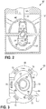
- a Wankle type rotary engine 60 is illustrated showing a rotor 62 rotatably disposed within a combustion chamber 64 of an engine block 66.
- the rotor 62 has a generally triangular shape having three apex sections 68.
- Permanent magnets 70 are provided adjacent each of the apex sections 68.
- An annular array of electromagnets 72 is disposed in the engine block 66 around the periphery of the combustion chamber 64, wherein the permanent magnets 70 pass by an area adjacent the electromagnets 72 when the rotor 62 rotates in respect of the engine block 66.
- An electrical current is selectively provided to each of the electromagnets 72 to produce a desired magnetic field.
- the produced magnetic field can be adapted to selectively attract and repel the permanent magnets 70 in the rotor 62, wherein selectively pulsing the electrical energy to each of the electromagnets 72 facilitates a rotation of the rotor 62 in respect of the engine block 66.
- a control system 80 is provided to control the operation of the engine 10 as shown in Fig. 4 .
- the control system 80 can also be used with the engine 60 and other engine types as desired. Use of the control system 80 is described herein with the engine 10 for exemplary purposes, as it is understood that the control system 80 can be similarly used with the engine 60 and other engine types.
- the control system is in electrical communication with selected sensors of the engine 10.
- the control system 80 receives inputs 90 from the sensors such as engine temperature, engine speed (RPM), engine load, vehicle speed, throttle position, crankshaft position, intake valve and exhaust valve position, intake manifold pressure, and exhaust gas properties, for example.
- a processor 82 is employed having a set of programmable instructions to process the inputs 90 and provide outputs 92 to control operations of the engine 10 such as spark timing, intake valve 34 and exhaust valve 36 position, fuel distribution to the cylinders, and fuel/air ratios, for example.
- An electronic storage device 84 can be provided and placed in electrical communication with the processor 82 to receive and store data such as the set of programmable instructions, the inputs 90 to and the outputs 92 from the processor 82, for example.
- the control system 80 is also effective to control the electromagnetic propulsion system by selectively causing the flow of electrical energy to the electromagnets 46 to produce the desired magnetic field to facilitate the reciprocating motion of the pistons 16 and the rotation of the crankshaft 22.
- the control system 80 selectively provides an electrical current to each of the electromagnets 46 to produce a desired magnetic field at a desired time for a desired period of time.
- the produced magnetic field selectively attracts and repels the permanent magnets 44, wherein selectively pulsing the electrical energy to each of the electromagnets 46 facilitates the reciprocating motion of the pistons 16 and the rotation of the crankshaft 22 in respect of the engine block 12.
- the electromagnets 46 and the permanent magnets 44 together with the piston 16, connecting rod 30, and crankshaft 22 form an electrical motor adapted to cause a rotation of the crankshaft 18 in respect of the engine block 12.
- the electrical motor can be employed to start the engine 10; thus, replacing the need for a starter as is typically used with engines.
- the electrical motor can be constructed separate from the engine 10, wherein the permanent magnets 44 are coupled to a rotatably mounted shaft, an annular array of electromagnets 46 are provided adjacent the shaft, and electrical energy is selectively pulsed to the electromagnets 46 to cause a rotation of the shaft.
- control system 80 can be adapted to cause the electromagnetic propulsion system to act as an engine braking system and an energy regeneration system.
- the control system 80 can selectively cause the flow of electrical energy to the electromagnets 46 to produce a magnetic field that cooperates with the magnetic field of the permanent magnets 44 to oppose the reciprocating motion of the pistons 16 and the rotation of the crankshaft 22.
- the control system 80 can cause an electrical current to be generated as the permanent magnets 44 pass by adjacent electromagnets 46.
- the electrical current generated can be employed to power electrical components associated with the engine 10 or stored as electrical energy employing electrical capacitors, electrical storage batteries, and the like, for example. Accordingly, it should be understood that the electromagnetic propulsion system can eliminate the need for providing an alternator for the engine 10.
- the control system 80 is also adapted to selectively deactivate the cylinder bore 14 upon the detection of selected operating conditions of the engine 10, wherein fuel and spark are not supplied to the cylinder bore 14 to minimize a consumption of fuel by the engine 10.
- the control system 80 can simultaneously control the flow of electrical energy to the electromagnets 46 to produce the desired magnetic field therearound. It should be understood that the control system 80 can cause the engine 10 to operate by a burning of the fuel in the cylinder bore 14, by the electromagnetic propulsion system, and a combination thereof.
- the cylinder bore 14 can be deactivated in respect of fuel during periods when the engine 10 is idling, periods where minimal power output is required, or other periods where the consumption of fuel can be minimized, for example.
- the electromagnetic propulsion system maintains the reciprocating motion of the piston 16 and the rotation of the crankshaft 22 when fuel is not being supplied to the cylinder bore 14. It should also be understood that by employing the electromagnetic propulsion system while burning the fuel in the cylinder bore 14, the quantity of NO x contained in exhaust from the cylinder bore 14 is minimized.
- the engine 10 is generally operated as is know to those skilled in the art of internal combustion engines.
- a fuel-air mixture is provided to the combustion chamber of the cylinder bore 14.
- An ignition spark is provided from the spark plug 42 to initiate the burning of the fuel within the combustion chamber.
- Energy from the burning of the fuel causes a reciprocating movement of the piston 16 within the cylinder bore 14 and a rotation of the crankshaft 22.
- the rotation of the crankshaft 22 is employed to mechanically power selected engine components such as an alternator, a fluid compressor, or a fluid pump, for example, as well as provide a motive force to propel the associated vehicle or the associated device such as an electric generator or a fluid pump, for example.
- the electromagnetic propulsion system together with the control system 80, selectively provides cooperating magnetic forces between engine components in relative motion with respect to each other to facilitate the reciprocating motion of the pistons 16 and the rotation of the crankshaft 22 and minimize the quantity of fuel being burned in the cylinder bores 14.
- the engine block 100 for a V-style internal combustion engine.
- the engine block 100 maximizes a fuel efficiency of the internal combustion engine.
- the engine block 100 is a V-style engine block having two cylinder banks 102, 104.
- Each of the cylinder banks 102, 104 includes four cylinder bores 114 to provide a total of eight cylinder bores 114 in the engine block 100 (the cylinder bores 114 labeled 1 through 8).
- the illustrated engine block 100 is used to construct a V8 internal combustion engine.
- the engine block 100 can have additional or fewer cylinder bores 114 to form a single cylinder engine or a multiple cylinder engine in a V, an inline, and an opposing cylinder bore configuration, for example. Additionally, it should be understood that the engine can be a four cycle or a two cycle engine, and can be based on the Otto cycle, Miller cycle, Scuderi split-cycle, or any other engine cycle now know or later developed.
- the cylinder bores 114 reciprocatingly receive a piston 116 therein.
- the pistons 116 include a top surface 118 and a skirt 120 depending therefrom.
- a crankshaft 122 having at least one throw 124 is rotatably mounted to a lower end of the engine block 100 employing a plurality of main caps 126 and associated main bearings (not shown).
- a connecting rod 130 is provided to connect the piston 116 to the crankshaft 122.
- One end of the connecting rod 130 is rotatably mounted to the crankshaft 122.
- An opposite end of the connecting rod 130 is pivotally attached to the piston 116, wherein a reciprocating motion of the piston 116 causes a rotation of the crankshaft 122.
- a cylinder head 132 is mounted to each of the cylinder banks 102, 104 of the engine block 100 and covers the cylinder bores 114 to define a fuel combustion chamber therein between the top surface 118 of the pistons 116 and the cylinder heads 132.
- At least one intake valve 134 and at least one exhaust valve 136 are reciprocatively disposed in the cylinder head 132 for each of the cylinder bores 114.
- the intake valve 134 selectively allows a fuel-air mixture to flow into the combustion chamber and the exhaust valve 136 selectively allows combusted fuel to be exhausted from the combustion chamber.
- the valves 134, 136 are mechanically actuated employing a valve train including an overhead cam shaft 138 and associated lifters 140 and valve springs 141.
- valve train can include a single overhead cam or a dual overhead cam and can be a single cam employing lifters, push rods, rocker arms, and compression springs, for example.
- solenoid actuated intake valves and exhaust valves can be employed.
- other types of cam assemblies now known or later developed can be used.
- the cylinder heads 132 may also include a fuel injector (not shown), wherein air is provided to the combustion chamber through the intake valve 134 and the fuel is directly injected into the combustion chamber through the fuel injector.
- the surfaces surrounding the combustion chamber such as surfaces forming the cylinder bores 114, the top surface 118 of the pistons 116, a surface of the cylinder heads 132, and surfaces of the intake valve 134 and the exhaust valve 136, for example, may be polished or include a coating of an industrial diamond to facilitate the reflection of heat energy away from the respective surfaces.
- the cylinder heads 132 also include means for initiating the combustion of the fuel within the combustion chamber.
- a plurality of spark plugs 142 having an electrode is provided to initiate the combustion of the fuel.
- the spark plugs 142 are threadably received in the cylinder head 132 to position the electrode within the combustion chamber.
- the spark plugs 142 employ electrical energy from an ignition system (not shown) to create a spark at the electrode to ignite the fuel within the respective combustion chambers. It should be understood that the engine block 100 can be used with a diesel engine which does not employ the spark plugs 142 to initiate the combustion of the fuel.
- At least one chamfer 160 is formed in the engine block 100 adjacent at least a portion of an upper edge of the cylinder bores 114. As shown in Figs. 5-6 , two of the chamfers 160 are provided for each of the cylinder bores 114, one chamfer 160 adjacent the intake valve 134 and the second chamfer 160 adjacent the exhaust valve 136. The chamfers 160 extend downwardly from the upper edge of the cylinder bores 114 a selected distance to a lower edge of the chamfers 160. As shown in Fig. 6 , a piston ring 144 is disposed on each of the pistons 116.
- the piston ring 144 is positioned below the lower edge of the chamfer 160 when the pistons 116 are at an uppermost reciprocating position (top dead center position) within the cylinder bores 114.
- a single chamfer 160 can be formed in each of the cylinder bores 114 such as a single chamfer 160 formed adjacent the intake valve 132, for example.
- more than two chamfers 160 can be formed in each of the cylinder bores 114 such as four chamfers 160, wherein one chamfer is provided for each valve in a four valve cylinder head, for example.
- the chamfers 160 cause a turbulent flow of the fuel air mixture into the cylinder bores 160, which maximizes the efficient ignition and burning of the fuel within the combustion chambers.
- the maximized ignition and burning of the fuel enables the ignition spark to be provided to the cylinder bores 114 when the pistons 116 are at about an uppermost reciprocating position (top dead center).
- the chamfers 160 also facilitate a flow of the combusted fuel-air mixture out of the cylinder bores 160.
- the control system 80 described hereinabove in respect of Fig. 4 may also be used with an engine employing the engine block 100.
- the control system is effective to selectively deactivate and reactivate any of the cylinder bores 114 in any desired sequence.
- a plurality of temperature sensors can be provided at selected locations of the engine block 100.
- the control system may selectively activate and deactivate the cylinder bores 114 to maintain a required power output of the engine, while minimizing temperature differences in the engine block 100.
- the control system 80 may cause the internal combustion engine formed from the engine block 100 to operate as a two, three, four, or eight cylinder engine, for example.
- cylinder firing orders may be employed to operate a 4-cycle internal combustion engine: 1-3-7-2-6-5-4-8 (8-cylinder mode), 1-7-6-4 followed by 3-2-5-8 (4-cylinder mode), 1-2-4 followed by 3-6-8 followed by 7-5 (3-cylinder mode), 1-6 followed by 3-5 followed by 7-4 followed by 2-8 (2-cylinder mode), for example.
- control system 80 can be employed to create any desired firing order and can be used with other engine block types to selectively deactivate and reactivate the cylinder bores 114.
- the control system 80 deactivates the cylinder bores 114 by stopping a flow of fuel thereto and stopping the flow of electrical energy to the spark plugs for the respective cylinder bores 114. It should be understood that the control system 80 may also stop the flow of air into the cylinder bores 114. The flow of fuel and air into the cylinder bores 114 may be stopped by selectively controlling a fuel/air intake system, a solenoid intake valve, or by causing an opening and closing of the intake valves 134 to cease.
- a water jacket (not shown) as is commonly known in the art is formed within the engine block 100 adjacent each of the cylinder bores 114 to facilitate transferring heat energy away from the area of the cylinder bores 114. Enabling the cylinder bores 114 to be selectively deactivated can result in lower engine operating temperatures as compared to engines not employing cylinder bore deactivation. Accordingly, the water jacket can have a reduced water volume as compared to water jackets provided for engines not employing cylinder bore deactivation. The reduced water volume of the water jacket maximizes a strength of the walls forming the cylinder bores 114 and generally provides for maximized rigidity of the engine block 100.
- control system 80 may be adapted to control the timing of the spark in respect of a position of the pistons 116 within the cylinder bores 114. It should be understood that the control system 80 is adapted to change the timing of the spark based upon the detected engine operating conditions. For example, the timing of the spark to the combustion chamber can be provided when the pistons 116 are at an uppermost position within the cylinder bores 114, typically called a top dead center position.
- four magnetic members may be disposed in a substantially evenly spaced annular configuration around a rotating harmonic balancer of a V8 engine.
- a magnetic pick-up is provided adjacent the harmonic balancer to sense the magnetic members of the harmonic balancer passing by the magnetic pick-up.
- the magnetic pick-up is in electrical communication with the control system 80 and provides a signal to the control system 80 each time one of the magnetic members passes thereby. The signal is employed by the control system 80 to control the timing of the spark in the combustion chambers.
- the electromagnetic propulsion system including the permanent magnets 44 and the electromagnets 46 described hereinabove and shown in Figs. 1-3 can be employed with the engine formed from the engine block 100.
- the control system 80 can be employed to cause the engine formed from the engine block 100 to operate by burning fuel in the cylinder bores 114, by the electromagnetic propulsion system, and a combination thereof.
- the cylinder bores 114 can be deactivated in respect of fuel during periods when the engine is idling, periods where minimal power output is required, or other periods where the consumption of fuel can be minimized, for example.
- the electromagnetic propulsion system maintains the reciprocating motion of the piston 116 and the rotation of the crankshaft 122 when fuel is not being supplied to and burned within the cylinder bores 114.
- the electromagnetic propulsion system can be employed while fuel is being supplied to and burned within the cylinder bores 114, wherein the electromagnetic propulsion system facilitates maintaining a desired power output from the engine while minimizing the fuel required to maintain the desired power output.
- Fig. 7 illustrates an alternative embodiment of the engine block 100 shown in Fig. 5 .
- an engine block 200 for a V-style internal combustion engine having two cylinder banks 202, 204.
- Each of the cylinder banks 202, 204 includes four cylinder bores 214 to provide a total of eight cylinder bores 214 in the engine block 200 (the cylinder bores 214 labeled 1 through 8).
- the illustrated engine block 200 is used to construct a V8 internal combustion engine.
- the engine block 200 can have additional or fewer cylinder bores 214 to form a single cylinder engine or a multiple cylinder engine in a V, an inline, and an opposing cylinder bore configuration, for example.
- the engine can be a four cycle or a two cycle engine, and can be based on the Otto cycle, Miller cycle, Scuderi split-cycle, or any other engine cycle now know or later developed.
- One of the cylinder bores 214 in each of the cylinder banks 202, 206 is an offset cylinder bore 215, wherein each of the offset cylinder bores 215 have a greater distance between the offset cylinder bore 215 and an adjacent cylinder bore 214 as compared to the distance between the other cylinder bores 214 in the cylinder banks 202, 204.
- the offset cylinder bores 215 are located at an end of the cylinder banks 202, 204, wherein the offset cylinder bores 215 are formed at opposite ends of the respective cylinder banks 202, 204. It should be understood that a cylinder head (not shown), a crankshaft (not shown), and other engine components (not shown) are adapted to accommodate the offset cylinder bores 215.
- the offset cylinder bores 215 facilitate an operation of the engine with only the offset cylinder bores 215 activated, wherein the supplying and burning of fuel in the remaining cylinder bores 214 is deactivated. Having the greater distance between the offset cylinder bores 215 and the adjacent cylinder bores 214 minimizes a transfer of heat energy between the offset cylinder bores 215 and the adjacent cylinder bores 214. Further, the minimized transfer of heat energy between the offset cylinder bores 215 and the adjacent cylinder bores 214 facilitate minimizing thermal differences between the other cylinder bores 214 in the cylinder banks 202, 204 when only the offset cylinder bores 215 are activated.
- the minimized thermal differences between the non-offset cylinder bores 214 maximizes an efficient and smooth operation of the engine upon the re-activation of the non-offset cylinder bores 214.
- the remaining structure and function of the engine block 200 and associated engine components are substantially the same as described herein above for the engine block 100.
- the crankshaft 300 includes a plurality of main journals 302 and a plurality of connecting rod journals 304.
- a throw 306 is interposed between adjacent main journals 302 and connecting rod journals 304.
- the main journals 302 and the connecting rod journals 304 include spaced apart beveled edges 308.
- the crank shaft 300 is rotatably mounted to a lower end of an engine block (not shown) employing a plurality of main bearings 310 and a plurality of main caps (not shown), wherein the main bearings 310 and the main caps are received by the main journals 302.
- the main bearings 310 are generally ring shaped, wherein two substantially c-shaped members are joined together around the main journals 302 to facilitate the rotation movement of the crank 300 in respect of the engine block.
- the main bearings 310 are tapered bearings having a cross sectional area in the general shape of an isosceles trapezoid.
- a plurality of connecting rods 312 is provided to connect pistons (not shown) to the connecting rod journals 304 of the crankshaft 300.
- One end of the connecting rods 312 is rotatably mounted to the connecting rod journals 304 of the crankshaft 300.
- Connecting rod bearings 314 are disposed between the end of the connecting rods 312 and the connecting rod journals 304.
- the connecting rod bearings 314 are generally ring shaped, wherein two substantially c-shaped members are joined together around the connecting rod journals 304 to facilitate the relative movement between the connecting rods 312 and the crankshaft 300.
- the connecting rod bearings 314 are tapered bearings having a cross sectional area in the general shape of an isosceles trapezoid.
- the connecting rods 312 extend into cylinder bores (not shown) of an engine block and an opposite end of the connecting rods 312 is pivotally attached to the pistons, wherein a reciprocating motion of the pistons causes a rotation of the crankshaft 300.
- the beveled edges 308 of the journals 302, 304 abut the tapered sides of the bearings 310, 314.
- the shorter of the parallel sides of the bearings 310, 314 forms an inner surface thereof which abuts a surface of the respective journals 302, 304.
- the beveled edges 308 and tapered sides of the bearings 310, 314 cooperate to minimize an axial movement of the crankshaft 300 in respect of the engine block and the axial movement of the connecting rods 312 in respect of the crankshaft 300.
- Each of the connecting rod journals 304 receives a pair of the connecting rods 312.
- a spacer 316 may be provided between the connecting rods 312 to minimize a friction therebetween, for example.
- the spacer 316 has a general shape of a washer, wherein two substantially c-shaped members are joined together around the connecting rod journal 304 to form the general washer shape of the spacer 316.
- separate connecting rod bearings 318, 320 can be provided for each of the connecting rods 312 received by the connecting rod journals 304, wherein the spacer 316 is disposed between the bearings 318, 320 and extends between the connecting rods 316.
- main bearings 310, the connecting rod bearings 314, 318, 320, and the spacers 316 can be provided with coatings to minimize frictional forces between moving components.
- coatings for example, Teflon®, industrial diamond, or any other suitable coating now known or later developed can be provided, for example.
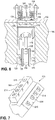
- a brace 400 that cooperates with an oil pan 430 to maximize the rigidity of an engine block 480 and minimize a deformation of the engine block 480 during an operation of an engine formed therewith.
- the brace 400 supports a fore main cap 482, an aft main cap 484, and one or more intermediate main caps 486.
- the main caps 482, 484, 486 rotatably support a crankshaft 488.
- Threaded fasteners 490 are typically employed to attach the main caps 482, 484, 486 to a lower end of the engine block 480.
- five main caps 482, 484, 486 are employed to rotatably support the crankshaft 488.
- the brace 400 can be employed with engines having fewer or additional main caps 482, 484, 486.
- the brace 400 can be employed with an engine having six main caps such as a V-10 engine or an engine having four main caps such as a V-6 engine.
- a plurality of connecting rods 490 is rotatably mounted to the crankshaft 488, each of which extend upwardly into a cylinder bore (not shown).
- the oil pan 450 defines a crankcase area 492 between an inner surface of the oil pan 450 and the lower end of the engine block 480.
- the brace 400 is a generally planar member having spaced apart ends 402, 404 extending from the fore main cap 482 to the aft main cap 484, and spaced apart sides 406, 408 extending from one side to an opposites side of the oil pan 450.
- a plurality of apertures 410 is formed in a central portion of the brace 400 adapted to receive the threaded fasteners 490 employed to attach the main caps 482, 484, 486 to the engine block 480.
- the fasteners 490 secure the brace 480 to the lowermost portion of the main caps 482, 484, 486 and secure the main caps 482, 484, 486 to the engine block 480.
- a plurality of openings 412 is formed in the brace 400 to facilitate a liquid such as a lubricating oil, for example, passing therethrough.
- a plurality of threaded bores 414 is formed in the sides 406, 408 of the brace 400 to receive a threaded fastener 416 as shown in Figs. 11-12 .
- the brace 400 can include reinforcing features such as a plurality of ribs formed therein or reinforcement members attached thereto.
- the oil pan 430 includes a skirt member 432 and a pan member 452.
- the skirt member 432 includes an upper edge 434 and a spaced apart lower edge 436.
- An upper flange 438 is formed adjacent the upper edge 434 which extends laterally outwardly from an inner surface of the skirt member 432. It should be understood that the upper flange 458 can be formed to extend laterally outwardly from an outer surface of the skirt member 432.
- the upper flange 438 includes a plurality of apertures 440 formed therein adapted to receive a threaded fastener 442 to secure the skirt member 432 to the lower potion of the engine block 480.
- a seal member such as a liquid sealant, an o-ring, and a flat gasket, for example, can be disposed between the upper flange 438 of the skirt member 432 and the engine block 480 to facilitate forming a substantially fluid tight seal therebetween.
- a lower flange 444 is formed adjacent the lower edge 436 of the skirt member 432 which extends laterally outwardly from an outer surface of the skirt member 432.
- the lower flange 444 includes a plurality of apertures 446, each of which is adapted to receive a threaded fastener 448.
- a plurality of apertures 450 is formed in the skirt member 452, wherein the apertures 450 are in substantial alignment with a plane adjacent the lowermost surface of the main caps 482, 484, 486.
- the threaded fasteners 416 extend through the apertures 450 and are received in the threaded bores 414 of the brace 400 to couple the brace 400 to the skirt member 432.
- one or more shims may be disposed between the main caps 482, 484, 486 and the brace 400 and/or the lower end of the engine block 480 and the skirt member 432 to facilitate an alignment of the apertures 450 in the skirt member 432 with the threaded bores 414 of the brace 400.
- the brace 400 can be formed having a substantially straight ends 402, 404 and straight sides 406, 408, wherein the periphery of the brace 400 abuts an inner surface of the skirt member 432.
- one or more seal members such as a liquid sealant, an O-ring, and a flat gasket, for example, can be disposed between the skirt member 432 and ends 402, 404 and the sides 406, 408 of the brace 400 to facilitate forming a substantially fluid tight seal therebetween.
- the pan member 452 of the oil pan 430 includes a closed bottom 454 and an open upper end 456 having a pan flange 458 formed adjacent thereto.
- the pan flange 458 extends outwardly from an outer surface of the pan member 452 and includes a plurality of apertures 460 formed therein.
- the apertures 460 of the pan flange 458 are adapted to be in substantial alignment with the apertures 446 formed in the lower flange 444 of the skirt member 432.
- the threaded fastener 448 is employed to join together the skirt member 432 and the pan member 452 and form a substantially fluid tight seal therebetween.
- one or more seal members such as a liquid sealant, an O-ring, and a flat gasket, for example, can be disposed between the lower flange 444 of the skirt member 432 and the pan flange 458 of the pan member 452 to facilitate forming the substantially fluid tight seal therebetween.
- a drain plug (not shown) can be provided in the closed bottom 454 of the pan member 452 to facilitate draining a fluid therefrom.
- the brace 400, the skirt member 432, and the pan member 452 can be adapted for the ends 402, 404 and/or the sides 406, 408 of the brace 400 to be disposed between the lower flange 444 of the skirt member 432 and the pan flange 458 of the pan member 452.
- the brace 400 can have other constructions such as a curvilinear construction wherein the sides 406, 408 abut the lower end of the engine block 480, thus eliminating the need for the skirt member 432.
- the brace 400 and the apertures 450 of the skirt member 432 can be adapted to position the sides 406, 408 of the brace 400 on a plane different from the plane of the lowermost surfaces of the main caps 482, 484, 486.
- the maximized rigidity and minimized distortion of the engine block 480 provided by the brace allows for minimized clearances between mating internal engine components. It has been found that clearances of about 0.0002 inches / 0,00508 mm can be employed as a result of minimizing distortion of the engine block 480 during the operation of the engine.
- the brace 400 can include one or more scraping members (not shown) extending therefrom to a location adjacent the crankshaft 488 and/or the connecting rods 492.
- the scraping members are adapted to remove lubricating fluid deposited on selected surfaces of the crankshaft 488 and/or the connecting rods 492 as the crankshaft 488 rotates and/or the connecting rods 492 reciprocate. Further, the scraping members can be formed separate from the brace 400 and disposed within the crankcase area 490 adjacent the crankshaft 488 and/or the connecting rods 492.
- the operating mass thereof is reduced which reduces the energy required to accelerate or maintain the rotational velocity of the crankshaft 488 and the connecting rods 492, and increases a fuel efficiency of the engine.
- a valley brace (not shown) can also be provided for an upper end of the engine block 480 to maximize the rigidity of the engine block 480 and minimize a deformation thereof during the operation of the engine.
- An exemplary brace for the upper end of the engine block 480 is disclosed in commonly owned U.S. Patent No. 7,258,094 , hereby incorporated herein by reference in its entirety.
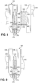
- Fig. 13 is a schematic representation of a lubrication system 500 for an engine 550.
- the lubrication system 500 directs a lubricating fluid 554 such as an oil, for example, to moving components of the engine 550.
- the lubrication system 500 includes a fluid pump 502.
- the fluid pump 502 can be mechanically driven by the engine 550, driven by an electrical motor, or driven by other means as desired.
- the fluid pump 502 includes a suction port 504 and a discharge port 506.
- the suction port 504 is in fluid communication with the lubricating fluid 554 disposed in an oil pan 552 of the engine 550.
- the discharge port 506 is in fluid communication with a network of fluid conduits 508, wherein the conduits 508 terminate at a discharge end 509 positioned adjacent a selected location within the engine 550.
- the network of fluid conduits 508 and discharge ends 509 thereof can direct the fluid 554 to main caps, surfaces forming cylinder bores of the engine 550, and to other locations of the engine 550 and associated engine components, for example.
- the lubrication system 500 can include a cooler 510, wherein the fluid 554 is caused to pass therethrough to remove heat energy from the fluid 554 prior to being distributed through the network of fluid conduits 508.
- the cooler 510 can be a fin type radiator cooler adapted to transfer heat energy to the atmosphere or other types of coolers.
- the cooler 510 can be employed to transfer heat energy to the fluid 554 or a separate heating element can be provided for the lubrication system 500 to facilitate maintaining the fluid 554 at or above a minimum selected temperature.
- the fluid capacity of the lubrication system 500 can be ten (10) quarts or more of the fluid 554 to facilitate cooling the fluid 554 to a selected temperature while maintaining an adequate supply of the fluid 554 to the engine 550.
- the engine 550 can include a plurality of cooperating fluid passageways (not shown) such as passageways formed in an engine block, for example, wherein the fluid passageways are in fluid communication with the discharge port 506 of the pump 502, to facilitate distributing the fluid 554 to selected locations within the engine 550.
- the lubrication system 500 provides an oil pressure of about 2 psi, which is lower than oil pressures typically employed for internal combustion engines.
- Employing the lubrication system 500 together with the reduced engine component clearances of 0.0002 (as discussed hereinabove in respect of the brace 400) facilitates the use of the lower oil pressure of about at least 2 psi.
- the lower oil pressure has been found to cause the lubricating oil to be received within the reduced clearances between engine components and provide lubrication to facilitate relative motion between engine components. It should be understood that the lubrication system 500 can provide higher oil pressures as desired.
- FIG. 14 A schematic representation of a crankcase vacuum system 600 for an engine 650 is illustrated in Fig. 14 .
- the crankcase vacuum system 600 includes a vacuum pump 602.
- the vacuum pump 602 can be mechanically driven by the engine 650 utilizing pulleys and a power transmission belt, driven by an electrical motor, or driven by other means as desired.
- the vacuum pump 602 includes a suction port 604 and a discharge port 606.
- the suction port 604 is in fluid communication with an internal crankcase area 654 of the engine 650 and the discharge port 606 is in fluid communication with a fluid recovery canister 608.
- the vacuum pump 602 evacuates air from the crankcase area 654 within the engine 650 to create an air pressure therein that is less than atmospheric pressure.
- the discharge port 606 of the vacuum pump 600 can be placed in fluid communication with the fluid recovery canister 608.
- the canister 608 is adapted to substantially remove lubricating fluid entrained in the air being drawn from the crankcase area 654.
- the canister 608 facilitates collecting the lubricating fluid therein and exhausting air therefrom.
- the air can be exhausted from the canister 608 through an air exhaust conduit 610.
- the air can be exhausted to an exhaust system 652 of the engine 650 and discharged to the atmosphere.
- the air can be exhausted to a catalytic converter or other component of the exhaust system 652.
- the exhaust system 652 is effective to collect and/or combust oil or other hydrocarbons entrained in the air and minimize emissions of hydrocarbons to the atmosphere from through the vacuum system 600.
- Lubricating fluid collected in the canister 608 can be reintroduced to the crankcase area 654 through a fluid recovery conduit 612.
- a valve 614 such as a check valve or an actuated valve, for example, can be provided in to control the flow of the lubricating fluid through the fluid recovery conduit 612 and militate against air being drawn into the crankcase area through the fluid recovery conduit 612.
- a fluid recovery pump 616 can be provided to propel lubricating fluid from the canister 608 to the crankcase area 654 of the engine 650.
- the mounting system 700 is adapted to mount an engine block 750 to a frame or uni-body of a vehicle, for example.
- the mounting system 700 includes a first plate 702 having spaced apart side edges 704, 706 and a second plate 708 having spaced apart side edges 710, 712.
- the first plate 702 is coupled to a front end of the engine block 750.
- the second plate 708 is coupled to a back end of the engine block 750.
- Each of the plates 702, 708 includes apertures 714 formed therein to receive fasteners 715 for coupling the plates 702, 708 to the engine block 750.
- the plates 702, 708 can be coupled to the engine block 750 employing a welding process or other joining process. Additional apertures may be formed in the plates 702, 708 for attaching other engine components to the engine block 750 and/or the plates 702, 708 such as an alternator, a compressor, a fluid pump, and a pulley, for example. Additionally, openings may be formed in the plates 702, 708 to provide for the passage of fluid conduits therethrough such as a coolant conduit and a refrigerant conduit, for example. It should be understood other openings can be formed in the plates 702, 708 as desired.
- the side edges 704, 706, 710, 712 of the respective plates 702, 708 extend outwardly from the sides of the engine block 750.
- Elongate rods 716, 718 are disposed between the plates 702, 708 and are coupled thereto. It should be understood that the rods 716, 718 can be coupled to the plates 702, 708 employing threaded fasteners and welding processes, for example.
- the rods 716, 718 are substantially parallel to the sides of the engine block 750.
- Mounting holes 720 are formed in the plates 702, 708 adjacent the respective sides 704, 706, 710, 712 thereof.
- the mounting holes 720 are adapted to receive a fastener such as a threaded fastener or a pin, for example, to couple the plates 702, 708 to the frame or the uni-body of the vehicle.
- a fastener such as a threaded fastener or a pin
- one or more brackets can be coupled to the plates 702, 708 and/or the frame or the uni-body of the vehicle to facilitate coupling the plates 702, 708 thereto.
- a dampening member can be employed such as a rubber engine mount, for example, with the fasteners to couple the plates 702, 708 to the engine block 750 and the frame or the uni-body of the vehicle.
- mounting the front end and the back end of the engine block 750 to the frame or uni-body using the mounting system 700 minimizes a twisting of the engine block 750 during an operation thereof. Further the mounting system 700 substantially isolates the engine block 750 from vibrations originating from suspension components of the vehicle. The minimized twisting of the engine block 750 and substantially isolating the engine block 750 from suspension vibrations minimizes distortion thereof and facilitates the use of the minimal clearances between mating internal engine components as previously described herein.
- the brace 400 and the mounting system 700 can be used together to minimize a distortion of an associated engine block.
- the valley brace disclosed in U.S Patent No. 7,258,094 can also be used with the brace 400 and the mounting system 700 provided to minimize a distortion of the associated engine block.
- the maximized cylinder wall thickness described hereinabove for the engine blocks 100, 200 can be employed with the associated engine block to maximize the rigidity thereof.
- the brace 400, the mounting system 700, the valley brace, and the maximized cylinder wall thickness minimize a distortion of the engine block during the operation of the engine. The minimized distortion enables clearances between surfaces of the engine block and surfaces of adjacent engine components as well as clearances between surfaces of adjacent engine components to be minimized.
- the maximized rigidity and minimized distortion allows clearances of about 0.0002 inches / 0,00508 mm to be employed.
- the reduced clearances maximize the efficient operation of the engine by minimizing undesired movements between surfaces of the engine block and surfaces of adjacent engine components and between surfaces of adjacent engine components.
- the internal combustion engine, the associated components, and the method of operation provide for an internal combustion engine having a minimized fuel consumption.
Landscapes
- Engineering & Computer Science (AREA)
- Mechanical Engineering (AREA)
- General Engineering & Computer Science (AREA)
- Power Engineering (AREA)
- Chemical & Material Sciences (AREA)
- Combustion & Propulsion (AREA)
- Valve Device For Special Equipments (AREA)
- Cylinder Crankcases Of Internal Combustion Engines (AREA)
Claims (12)
- Verbrennungsmotor (10), umfassend:eine Motorblockanordnung (12);eine Motorkomponente (16), die in der Motorblockanordnung (12) angeordnet und in Bezug auf eine zentrale Längsachse der Motorkomponente (16) und relativ zu der Motorblockanordnung (12) bewegbar ist, wobei die Motorblockanordnung (12) ferner eine Zylinderbank (102, 104) umfasst, beinhaltend eine Vielzahl von darin ausgebildeten Zylinderbohrungen (114) und einen Zylinderkopf (32), der an der Zylinderbank (102, 104) montiert ist und die Zylinderbohrungen (114) abdeckt, und wobei die Motorkomponente (16) ein Kolben (16) ist, der sich hin- und herbewegend in den Zylinderbohrungen (114) angeordnet ist, und eine Kurbelwelle (22), die drehbar an der Zylinderblockanordnung (12) montiert ist;mindestens ein Elektromagnet (46) in der Motorblockanordnung (12) angeordnet ist, wobei der mindestens eine Elektromagnet (46) an mindestens einen von der Zylinderbank (102, 104) und dem Zylinderkopf (32) benachbart zu den Zylinderbohrungen (114) gekoppelt ist,dadurch gekennzeichnet, dass die Motorkomponente einen Dauermagneten beinhaltet, der in den Kolben eingebettet ist, und mindestens einen Dauermagneten, der in die Kurbelwelle eingebettet ist; und gekennzeichnet durchein Steuerungssystem (80) dazu ausgelegt ist, dem mindestens einen Elektromagneten (46) einen elektrischen Strom bereitzustellen, um ein gewünschtes Magnetfeld zu produzieren, wobei das Magnetfeld des Elektromagneten (46) mit einem Magnetfeld des Dauermagneten (44) zusammenwirkt, um eine Bewegung der Motorkomponente (16) in Bezug auf ihre zentrale Längsachse und relativ zu der Motorblockanordnung (12) zu bewirken; und ferner gekennzeichnet durcheine magnetisierte Verbindungsstange (30) mit entgegengesetzten Enden, wobei ein erstes Ende drehbar an der Kurbelwelle (22) angebracht ist und ein zweites Ende an den Kolben (16) gekoppelt ist, wobei eine magnetische Polarität der magnetisierten Verbindungsstange (30) eine magnetische Anziehung zwischen dem ersten Ende und der Kurbelwelle (22) und eine magnetische Anziehung zwischen dem zweiten Ende und dem Kolben (16) verursacht.
- Verbrennungsmotor (10) nach Anspruch 1, wobei die Motorblockanordnung (12) eine Halterung (50) beinhaltet, und wobei die Halterung (50) Elektromagneten (46') beinhaltet.
- Verbrennungsmotor (10) nach Anspruch 1, wobei mindestens eine der Zylinderbohrungen (114) in der Zylinderbank (102, 104) in Bezug auf die übrigen Zylinderbohrungen (114) versetzt ist.
- Verbrennungsmotor (10) nach Anspruch 4, wobei mindestens eine Fase (160) in einer Wand ausgebildet ist, welche die Zylinderbohrungen (114) in der Zylinderbank (102, 104) ausbildet, wobei die Fase (160) dem Zylinderkopf (132) benachbart ausgebildet ist.
- Verbrennungsmotor (10) nach Anspruch 1, ferner umfassend eine Zündkerze (42), die in dem Zylinderkopf (32) angeordnet ist, der eine elektrische Wicklung dortherum aufweist, wobei die Zündkerze und die elektrische Wicklung den Elektromagneten ausbilden.
- Verbrennungsmotor (10) nach Anspruch 1, wobei
der Zylinderkopf (32) ein Einlassventil (34) und ein Auslassventil (36) in Fluidaustausch mit jeder der Zylinderbohrungen (14) beinhaltet, und wobei an einem unteren Ende des Motorblocks (12) eine Ölwanne (452) montiert ist, um einen Kurbelgehäusebereich (492) des Motors (10) auszubilden. - Verbrennungsmotor (10) nach Anspruch 6, wobei die Kurbelwelle (300) eine Vielzahl beabstandeter Kröpfungen (306) beinhaltet, wobei ein Abstand zwischen den Kröpfungen einen Hauptzapfen (302) und einen Verbindungsstangenzapfen (304) beinhaltet, wobei der Hauptzapfen (302) und der Verbindungsstangenzapfen (304) abgeschrägte, voneinander beabstandete Kanten (308) beinhalten, die an entsprechende voneinander beabstandete Kröpfungen (306) angrenzen, ein angeschrägtes Hauptlager (310, 314), das um das Hauptlager (302) zwischen den abgeschrägten Kanten (308) davon aufgenommen ist, und ein angeschrägtes Verbindungsstangenlager, das rings um den Verbindungsstangenzapfen (304) zwischen abgeschrägten Kanten (308) davon aufgenommen ist.
- Verbrennungsmotor (10) nach Anspruch 7, wobei ein Paar der Verbindungsstangen drehbar an dem ersten Ende an dem Verbindungsstangenzapfen angebracht ist, wobei das Verbindungsstangenlager zwischen dem Paar von Verbindungsstangen und der Kurbelwelle und einem rings um den Verbindungsstangenzapfen aufgenommenen Abstandhalter zwischengeschaltet ist, und zwischen dem Paar der Verbindungsstangen zwischengeschaltet ist.
- Verbrennungsmotor nach Anspruch 8, wobei ein Paar der Verbindungsstangenlager (314) mit dem Abstandhalter (316) versehen ist, der zwischen die Verbindungsstangenlager (314) zwischengeschaltet ist und sich zwischen dem Paar von Verbindungsstangen (312) erstreckt.
- Verbrennungsmotor (10) nach Anspruch 6, ferner umfassend:eine Halterung für eine Ölwanne (400) mit einem zentralen Abschnitt und einem Paar beabstandeter Seiten (406, 408), wobei der zentrale Abschnitt an ein unteres Ende des Motorblocks angrenzend an die Kurbelwelle gekoppelt ist und die beabstandeten Seiten (406, 408) an die Ölwanne (400) gekoppelt sind; oderferner umfassend ein Schmiersystem (500) mit einer Fluidpumpe (502) mit einem Sauganschluss (504) und einem Auslassanschluss (506), wobei der Sauganschluss (504) in einem Fluidaustausch mit einem Fluid steht, das in der Ölwanne (552) angeordnet ist, und der Auslassanschluss (506) in einem Fluidaustausch mit einem Fluidkreis (508) mit einem Auslassende steht, das in dem Verbrennungsmotor (10) angrenzend an eine Komponente davon angeordnet ist, wobei die Fluidpumpe (502) einen Strom des Fluides von der Ölwanne (552) durch den Fluidkreis (508) verursacht, sowie dass das Fluid aus dem der Komponente benachbarten Auslassende ausgelassen wird, wobei das Schmiersystem (500) einen Fluiddruck von etwa 2 psi/0,137 bar bereitstellt; oderferner umfassend ein Kurbelgehäuse-Vakuumsystem (600), das eine Fluidpumpe (602) mit einem Sauganschluss (604) und einem Auslassanschluss (606) beinhaltet, wobei der Sauganschluss (604) in einem Fluidaustausch mit dem Kurbelgehäusebereich (654) des Verbrennungsmotors (650) und der Auslassanschluss (606) in einem Fluidaustausch mit der Atmosphäre steht, die Fluidpumpe (602) Luft aus dem Kurbelgehäusebereich (654) zieht und die Luft an die Atmosphäre auslässt, um innerhalb des Kurbelgehäusebereichs (654) einen Druck zu erzeugen, der niedriger als ein Druck der Atmosphäre ist; oderferner umfassend ein Motorblockmontagesystem (700), das eine erste Platte (702) mit voneinander beabstandeten Seitenkanten (704, 706) und eine zweite Platte (708) mit voneinander beabstandeten Seitenkanten (710, 712) beinhaltet, wobei die erste Platte (702) an den Motorblock (750) angrenzend an ein vorderes Ende davon gekoppelt ist und die zweite Platte (708) an den Verbrennungsmotor (10) angrenzend an ein hinteres Ende davon gekoppelt ist, wobei die Seitenkanten (704, 706) der ersten Platte (702) und die Seitenkanten (710, 712) der zweiten Platte (708) an einen Stützrahmen (716, 718) gekoppelt sind.
- Verfahren zum Maximieren von Kraftstoffeffizienz eines Verbrennungsmotors (10), umfassend folgende Schritte:Bereitstellen eines Verbrennungsmotors (10), beinhaltend einen Motorblock (12) mit einer Zylinderbank (102, 104), beinhaltend eine Vielzahl von darin ausgebildeten Zylinderbohrungen (114), einen Kolben (16) der sich hin- und herbewegend in jeder der Zylinderbohrungen (114) angeordnet ist, wobei der Kolben (16) in Bezug auf eine zentrale Längsachse des Kolbens (16) und relativ zu dem Motorblock (12) bewegbar ist;Bereitstellen einer Kurbelwelle (22), die drehbar an dem Motorblock (12) montiert ist, eine Vielzahl von Verbindungsstangen (30) mit einem ersten Ende und einem zweiten Ende, wobei das erste Ende drehbar an der Kurbelwelle (22) angebracht ist und das zweite Ende mit dem Kolben (16) gekoppelt ist, wobei ein Verbrennen eines Kraftstoffs innerhalb der Zylinderbohrungen (114) eine Hin- und Herbewegung der Kolben (16) und eine Rotation der Kurbelwelle (22) in Bezug auf den Motorblock (12) verursacht,dadurch gekennzeichnet, dass der Kolben (16) einen darin eingebetteten Dauermagneten (44) beinhaltet, wobei die Verbindungsstangen (30) magnetisiert sind und entgegengesetzte Enden aufweisen, ein erstes Ende drehbar an der Kurbelwelle (22) angebracht und ein zweites Ende an die Kolben (16) gekoppelt ist,
wobei eine magnetische Polarität der magnetisierten Verbindungsstangen (30) eine magnetische Anziehung zwischen dem ersten Ende und der Kurbelwelle (22) und eine magnetische Anziehung zwischen dem zweiten Endes und dem Kolben (16) verursacht;Bereitstellen einer Vielzahl von Elektromagneten (46) mit dem Motorblock (12), wobei die Vielzahl von Elektromagneten (46) an die Zylinderbank (102, 104), den Zylinderbohrungen (114) benachbart, gekoppelt sind;Bereitstellen eines Steuerungssystems (80), um den Elektromagneten (46) einen elektrischen Strom bereitzustellen, um ein gewünschtes Magnetfeld zu produzieren, wobei das Magnetfeld der Elektromagneten (46) mit einem Magnetfeld der Dauermagneten (44) zusammenwirkt, um eine Bewegung des Kolbens (16) und der Kurbelwelle (22) in Bezug auf den Motorblock (12) zu bewirken. - Verfahren nach Anspruch 11, ferner umfassend folgende Schritte:Deaktivieren einer Zylinderbohrung (114) des Verbrennungsmotors (10) durch Beenden der Verbrennung des Kraftstoffs darin, wobei das Deaktivieren der Zylinderbohrung (114) einen Verbrauch des Kraftstoffs durch den Verbrennungsmotor (10) minimiert; oderVeranlassen, dass das Magnetfeld der Elektromagneten (46) mit dem Magnetfeld der Dauermagneten (44) zusammenwirkt, um eine Bewegung des Kolbens (16) mit der Vielzahl von Dauermagneten (44) und der Kurbelwelle (22) in Bezug auf den Motorblock (12) zu erleichtern; oderVeranlassen, dass das Magnetfeld des Elektromagneten (46) mit dem Magnetfeld des Dauermagneten (44) zusammenwirkt, um einer Bewegung des Kolbens (16) mit der Vielzahl von Dauermagneten (44) und der Kurbelwelle (22) in Bezug auf den Motorblock (12) entgegenzuwirken.
Applications Claiming Priority (3)
| Application Number | Priority Date | Filing Date | Title |
|---|---|---|---|
| US17874209P | 2009-05-15 | 2009-05-15 | |
| US25187609P | 2009-10-15 | 2009-10-15 | |
| PCT/US2010/034979 WO2010132818A1 (en) | 2009-05-15 | 2010-05-14 | Internal combustion engine and method of operating same |
Publications (3)
| Publication Number | Publication Date |
|---|---|
| EP2430735A1 EP2430735A1 (de) | 2012-03-21 |
| EP2430735A4 EP2430735A4 (de) | 2017-03-29 |
| EP2430735B1 true EP2430735B1 (de) | 2019-09-25 |
Family
ID=43067470
Family Applications (1)
| Application Number | Title | Priority Date | Filing Date |
|---|---|---|---|
| EP10775627.2A Active EP2430735B1 (de) | 2009-05-15 | 2010-05-14 | Verbrennungsmotor und betriebsverfahren dafür |
Country Status (6)
| Country | Link |
|---|---|
| US (7) | US8616175B2 (de) |
| EP (1) | EP2430735B1 (de) |
| CN (1) | CN102640402B (de) |
| CA (1) | CA2767645C (de) |
| ES (1) | ES2761304T3 (de) |
| WO (1) | WO2010132818A1 (de) |
Families Citing this family (25)
| Publication number | Priority date | Publication date | Assignee | Title |
|---|---|---|---|---|
| EP2430735B1 (de) * | 2009-05-15 | 2019-09-25 | Douglas A. Pelmear | Verbrennungsmotor und betriebsverfahren dafür |
| DE102009051517A1 (de) * | 2009-10-31 | 2011-05-05 | Bayerische Motoren Werke Aktiengesellschaft | Kurbelgehäuse |
| KR20130061576A (ko) * | 2011-12-01 | 2013-06-11 | 현대자동차주식회사 | 엔진의 밸런싱 장치 |
| CN102705074B (zh) * | 2012-05-25 | 2015-09-30 | 浙江吉利汽车研究院有限公司杭州分公司 | 混合动力装置 |
| US8944024B2 (en) * | 2012-07-25 | 2015-02-03 | Southwest Research Institute | Magnetic bearing for use in reciprocating internal combustion engines |
| WO2015079440A1 (en) * | 2013-11-26 | 2015-06-04 | Shai Aviezer | Improved thermal management of combustion engines |
| FR3027057B1 (fr) * | 2014-10-13 | 2019-10-04 | IFP Energies Nouvelles | Moteur thermique comportant une generatrice lineaire de courant electrique |
| US10429095B2 (en) * | 2015-02-04 | 2019-10-01 | Todd Gerard Schmidt | Schmitty compressor |
| US20150159549A1 (en) * | 2015-02-17 | 2015-06-11 | Electro-Motive Diesel, Inc. | Engine block for internal combustion engine |
| US9689350B2 (en) * | 2015-05-27 | 2017-06-27 | Ford Global Technologies, Llc | System and methods for mechanical vacuum pump exhaust |
| CN105257449A (zh) * | 2015-10-23 | 2016-01-20 | 屈国栋 | 一种发动机及车辆 |
| DE102015222236B3 (de) * | 2015-11-11 | 2017-04-27 | Ford Global Technologies, Llc | Elektromagnetisches Zündsystem für einen Verbrennungsmotor, sowie Verbrennungsmotor mit Zündsystem |
| DE102015222240A1 (de) | 2015-11-11 | 2017-05-11 | Ford Global Technologies, Llc | Elektromagnetisches Zündsystem für einen Verbrennungsmotor, sowie Verbrennungsmotor mit Zündsystem |
| DE202015106332U1 (de) | 2015-11-11 | 2015-12-03 | Ford Global Technologies, Llc | Elektromagnetisches Zündsystem für einen Verbrennungsmotor, sowie Verbrennungsmotor mit Zündsystem |
| CN108884783A (zh) * | 2016-03-31 | 2018-11-23 | 洋马株式会社 | 发动机装置 |
| CN105840267B (zh) * | 2016-05-06 | 2018-05-25 | 陈光明 | 可控弹性内燃机 |
| CN105840337B (zh) * | 2016-05-06 | 2018-05-25 | 陈光明 | 可控弹性内燃机 |
| CN105840338B (zh) * | 2016-05-06 | 2018-05-25 | 陈光明 | 可控弹性内燃机 |
| CN105952525A (zh) * | 2016-06-23 | 2016-09-21 | 陆克勇 | 综合动力发动机 |
| JP6572868B2 (ja) * | 2016-11-04 | 2019-09-11 | 株式会社豊田中央研究所 | 内燃機関の点火装置 |
| US10612622B2 (en) * | 2018-05-04 | 2020-04-07 | Schaeffler Technologies AG & Co. KG | Magnetic engine vibration isolator |
| CN111878289B (zh) * | 2020-07-31 | 2021-06-25 | 大连海事大学 | 一种磁场调制灯浮标波浪能发电装置 |
| US20220385137A1 (en) * | 2021-05-27 | 2022-12-01 | Jerome Walter Michael Loach | System for magnetic piston |
| IT202200011588A1 (it) * | 2022-06-01 | 2023-12-01 | Crow Tech S R L | Sistema di ottimizzazione per motore a scoppio |
| DE112023006588A5 (de) * | 2023-06-30 | 2026-05-07 | Anil Hassam | Elektromagnetischer Motor |
Family Cites Families (37)
| Publication number | Priority date | Publication date | Assignee | Title |
|---|---|---|---|---|
| US1351763A (en) * | 1916-05-18 | 1920-09-07 | Curtiss Aeroplane & Motor Co | Aeronautical motor |
| US2060263A (en) * | 1936-03-13 | 1936-11-10 | Ross J Sweeney | Internal combustion engine |
| US2377621A (en) * | 1942-05-29 | 1945-06-05 | Bendix Aviat Corp | Ignition apparatus |
| US2553296A (en) * | 1948-09-07 | 1951-05-15 | James W Brown | Piston |
| US2849994A (en) * | 1956-05-29 | 1958-09-02 | Ray C Barker | Excess breather oil recovery system |
| DE1921068A1 (de) * | 1969-04-25 | 1970-11-12 | Daimler Benz Ag | Vorrichtung zum Entlueften des Kurbelgehaeuses einer Brennkraftmaschine |
| JPS5371728A (en) * | 1976-12-08 | 1978-06-26 | Nissan Motor Co Ltd | Controller for number of cylinders for feeding fuel |
| US4213428A (en) * | 1977-02-22 | 1980-07-22 | Phecell Bradley | Electromagnetic augmentation of internal combustion engines |
| US4317058A (en) * | 1979-12-28 | 1982-02-23 | Troy L. Cook | Electro-magnetic reciprocating engine |
| US4510420A (en) * | 1980-12-12 | 1985-04-09 | Servo Technology Corp. | Servo rotary motor |
| US4631455A (en) * | 1983-11-15 | 1986-12-23 | Taishoff Howard A | Method and apparatus for converting a conventional internal combustion engine into a high speed electric motor and generator |
| US5089129A (en) * | 1990-05-04 | 1992-02-18 | Brigman Bernard B | Fluid contaminate filtration system including a filter, a contaminate particle trap, and a cold start fluid circulation system |
| US5190013A (en) * | 1992-01-10 | 1993-03-02 | Siemens Automotive L.P. | Engine intake valve selective deactivation system and method |
| US5457349A (en) * | 1993-06-30 | 1995-10-10 | Gifford; Leland W. | Reciprocating electromagnetic engine |
| GB2286928A (en) * | 1994-02-25 | 1995-08-30 | Solomos Foti Solomou | Magnetic piston motor |
| US5469004A (en) * | 1994-05-13 | 1995-11-21 | Jachim; Frank M. | Electric vehicle solenoid motor |
| US5592036A (en) * | 1994-07-18 | 1997-01-07 | Pino; Raul M. | Engine construction |
| DE19537192C1 (de) * | 1995-10-06 | 1997-01-09 | Porsche Ag | Kurbelwellenlagerung einer mehrzylindrigen Brennkraftmaschine |
| JP3820647B2 (ja) * | 1996-09-30 | 2006-09-13 | 日産自動車株式会社 | エンジンのトルクダウン制御装置 |
| US5762039A (en) * | 1997-01-20 | 1998-06-09 | The Cessna Aircraft Company | Barrel engine connecting rod |
| US5881686A (en) * | 1997-09-08 | 1999-03-16 | D.L.S. Cycle Products, Inc. | Crankcase breather valve for engines with synchronous piston movement |
| US6230680B1 (en) * | 2000-02-16 | 2001-05-15 | Thomas A Pirone | High-precision three-valve motorcycle engine lubrication |
| US6360724B1 (en) * | 2000-05-18 | 2002-03-26 | Brunswick Corporation | Method and apparatus for controlling the power output of a homogenous charge internal combustion engine |
| JP4155714B2 (ja) * | 2001-01-10 | 2008-09-24 | 本田技研工業株式会社 | 内燃機関 |
| WO2002070871A2 (de) * | 2001-03-07 | 2002-09-12 | Hengst Gmbh & Co. Kg | Einrichtung für die entlüftung des kurbelgehäuses einer brennkraftmaschine |
| JP2002349304A (ja) | 2001-05-18 | 2002-12-04 | Yamaha Motor Co Ltd | 気筒数制御エンジン |
| US7245050B2 (en) * | 2001-08-20 | 2007-07-17 | Honda Giken Kogyo Kabushiki Kaisha | Internal combustion engine |
| US6928974B1 (en) * | 2004-01-30 | 2005-08-16 | Demetrios Markou | Reinforcement plate for a reciprocating engine |
| US7105958B1 (en) * | 2004-11-15 | 2006-09-12 | Shimon Elmaleh | Electro-magnetic engine |
| EP1920141A1 (de) * | 2005-04-14 | 2008-05-14 | Gerald Beaulieu | Elektromagnetischer motor |
| US7258094B1 (en) * | 2005-09-27 | 2007-08-21 | Douglas A Pelmear | Engine block component brace |
| JP2007189824A (ja) * | 2006-01-12 | 2007-07-26 | Nisca Corp | マグネットロータ及びこれを用いた電磁駆動装置並びにこの光量調整装置を備えた光学機器 |
| US7501725B2 (en) * | 2006-08-21 | 2009-03-10 | Steve Parker | Method of converting piston driven engines to operate on electricity |
| US7950356B2 (en) * | 2007-10-09 | 2011-05-31 | The Invention Science Fund I, Llc | Opposed piston electromagnetic engine |
| US7793634B2 (en) * | 2008-09-25 | 2010-09-14 | Shimon Elmaleh | Electro-magnetic internal combustion engine |
| US8324762B2 (en) * | 2008-11-21 | 2012-12-04 | Christian Harvey Keller | Magnetically propelled engine with magnetic field reduction |
| EP2430735B1 (de) * | 2009-05-15 | 2019-09-25 | Douglas A. Pelmear | Verbrennungsmotor und betriebsverfahren dafür |
-
2010
- 2010-05-14 EP EP10775627.2A patent/EP2430735B1/de active Active
- 2010-05-14 CA CA2767645A patent/CA2767645C/en active Active
- 2010-05-14 WO PCT/US2010/034979 patent/WO2010132818A1/en not_active Ceased
- 2010-05-14 CN CN201080031937.5A patent/CN102640402B/zh not_active Expired - Fee Related
- 2010-05-14 ES ES10775627T patent/ES2761304T3/es active Active
- 2010-05-14 US US12/780,637 patent/US8616175B2/en active Active
-
2013
- 2013-11-18 US US14/082,286 patent/US8991356B2/en active Active
-
2015
- 2015-02-06 US US14/615,995 patent/US9915209B2/en active Active
-
2018
- 2018-03-09 US US15/916,328 patent/US10208682B2/en active Active
-
2019
- 2019-01-09 US US16/243,201 patent/US10724446B2/en active Active
-
2020
- 2020-06-18 US US16/905,188 patent/US11274612B2/en active Active
-
2022
- 2022-02-09 US US17/667,644 patent/US11808220B2/en active Active
Non-Patent Citations (1)
| Title |
|---|
| None * |
Also Published As
| Publication number | Publication date |
|---|---|
| CA2767645C (en) | 2019-05-21 |
| CN102640402B (zh) | 2015-04-15 |
| CN102640402A (zh) | 2012-08-15 |
| EP2430735A1 (de) | 2012-03-21 |
| US11274612B2 (en) | 2022-03-15 |
| US20220163000A1 (en) | 2022-05-26 |
| US11808220B2 (en) | 2023-11-07 |
| US8991356B2 (en) | 2015-03-31 |
| WO2010132818A1 (en) | 2010-11-18 |
| US8616175B2 (en) | 2013-12-31 |
| US20140074384A1 (en) | 2014-03-13 |
| US20150184598A1 (en) | 2015-07-02 |
| US20180195442A1 (en) | 2018-07-12 |
| US10208682B2 (en) | 2019-02-19 |
| ES2761304T3 (es) | 2020-05-19 |
| CA2767645A1 (en) | 2010-11-18 |
| US9915209B2 (en) | 2018-03-13 |
| EP2430735A4 (de) | 2017-03-29 |
| US20190145324A1 (en) | 2019-05-16 |
| US10724446B2 (en) | 2020-07-28 |
| US20100288214A1 (en) | 2010-11-18 |
| US20200378318A1 (en) | 2020-12-03 |
Similar Documents
| Publication | Publication Date | Title |
|---|---|---|
| US11808220B2 (en) | Internal combustion engine and method of operating same | |
| WO2007115176A2 (en) | Methods and apparatus for operating an internal combustion engine | |
| US6065440A (en) | Internal combustion engine with binary cylinder sizing for variable power output | |
| EP1360402B1 (de) | Flugzeugtriebwerk mit luft- und wassergekühlten gegenüberliegenden zylindern | |
| JP5478741B2 (ja) | 低燃費低エミッション2ストロークエンジン | |
| EP0527146A1 (de) | Schwingkolbenmotor oder maschine mit quaderförmigem kolben | |
| WO2007115170A2 (en) | Methods and apparatus for operating an internal combustion engine | |
| CN103233779B (zh) | 旋转式发动机的进排气结构 | |
| CN103206250B (zh) | 摆动式可变多缸空气动力发动机 | |
| CN203230459U (zh) | 旋转式发动机 | |
| US10487703B2 (en) | Rotary valve engine system | |
| JP5185974B2 (ja) | 4サイクルエンジン | |
| WO2007047494A1 (en) | Engine having axiallyy opposed cylinders | |
| JP2003097289A (ja) | 傾斜シリンダ型汎用4サイクルエンジン | |
| CN1831304A (zh) | 连续可变气门正时配气机构活塞式内燃机 | |
| CN104141511B (zh) | 旋转式发动机的推动旋转系统 | |
| KR20020008555A (ko) | 압축공기를 동력매체로 하는 엔진 | |
| RS1590U1 (sr) | Motor sa unutrašnjim sagorevanjem sa propusnim klipom i suprotno spregnutnim radilicama | |
| CN103233780A (zh) | 旋转式发动机的轴系统 | |
| JPH09151748A (ja) | 並列レシプロエンジン | |
| CN103233781A (zh) | 旋转式发动机 | |
| CN103206249A (zh) | 用于摆动式可变多缸空气动力发动机的控制机构 |
Legal Events
| Date | Code | Title | Description |
|---|---|---|---|
| PUAI | Public reference made under article 153(3) epc to a published international application that has entered the european phase |
Free format text: ORIGINAL CODE: 0009012 |
|
| 17P | Request for examination filed |
Effective date: 20120109 |
|
| AK | Designated contracting states |
Kind code of ref document: A1 Designated state(s): AL AT BE BG CH CY CZ DE DK EE ES FI FR GB GR HR HU IE IS IT LI LT LU LV MC MK MT NL NO PL PT RO SE SI SK SM TR |
|
| DAX | Request for extension of the european patent (deleted) | ||
| REG | Reference to a national code |
Ref country code: DE Ref legal event code: R079 Ref document number: 602010061234 Country of ref document: DE Free format text: PREVIOUS MAIN CLASS: H02K0033000000 Ipc: H02K0007180000 |
|
| RA4 | Supplementary search report drawn up and despatched (corrected) |
Effective date: 20170223 |
|
| RIC1 | Information provided on ipc code assigned before grant |
Ipc: F01M 1/02 20060101ALI20170218BHEP Ipc: F02B 63/04 20060101ALI20170218BHEP Ipc: F02B 75/18 20060101ALI20170218BHEP Ipc: H01T 13/00 20060101ALI20170218BHEP Ipc: H02K 7/18 20060101AFI20170218BHEP Ipc: H02K 33/16 20060101ALI20170218BHEP Ipc: H02K 53/00 20060101ALI20170218BHEP Ipc: F02D 17/02 20060101ALI20170218BHEP Ipc: F02F 1/18 20060101ALI20170218BHEP Ipc: F02B 77/14 20060101ALI20170218BHEP Ipc: H02K 33/00 20060101ALI20170218BHEP |
|
| GRAP | Despatch of communication of intention to grant a patent |
Free format text: ORIGINAL CODE: EPIDOSNIGR1 |
|
| STAA | Information on the status of an ep patent application or granted ep patent |
Free format text: STATUS: GRANT OF PATENT IS INTENDED |
|
| INTG | Intention to grant announced |
Effective date: 20190514 |
|
| GRAS | Grant fee paid |
Free format text: ORIGINAL CODE: EPIDOSNIGR3 |
|
| GRAA | (expected) grant |
Free format text: ORIGINAL CODE: 0009210 |
|
| STAA | Information on the status of an ep patent application or granted ep patent |
Free format text: STATUS: THE PATENT HAS BEEN GRANTED |
|
| AK | Designated contracting states |
Kind code of ref document: B1 Designated state(s): AL AT BE BG CH CY CZ DE DK EE ES FI FR GB GR HR HU IE IS IT LI LT LU LV MC MK MT NL NO PL PT RO SE SI SK SM TR |
|
| REG | Reference to a national code |
Ref country code: GB Ref legal event code: FG4D |
|
| REG | Reference to a national code |
Ref country code: CH Ref legal event code: EP |
|
| REG | Reference to a national code |
Ref country code: AT Ref legal event code: REF Ref document number: 1184779 Country of ref document: AT Kind code of ref document: T Effective date: 20191015 |
|
| REG | Reference to a national code |
Ref country code: IE Ref legal event code: FG4D |
|
| REG | Reference to a national code |
Ref country code: DE Ref legal event code: R096 Ref document number: 602010061234 Country of ref document: DE |
|
| REG | Reference to a national code |
Ref country code: NL Ref legal event code: MP Effective date: 20190925 |
|
| PG25 | Lapsed in a contracting state [announced via postgrant information from national office to epo] |
Ref country code: SE Free format text: LAPSE BECAUSE OF FAILURE TO SUBMIT A TRANSLATION OF THE DESCRIPTION OR TO PAY THE FEE WITHIN THE PRESCRIBED TIME-LIMIT Effective date: 20190925 Ref country code: FI Free format text: LAPSE BECAUSE OF FAILURE TO SUBMIT A TRANSLATION OF THE DESCRIPTION OR TO PAY THE FEE WITHIN THE PRESCRIBED TIME-LIMIT Effective date: 20190925 Ref country code: NO Free format text: LAPSE BECAUSE OF FAILURE TO SUBMIT A TRANSLATION OF THE DESCRIPTION OR TO PAY THE FEE WITHIN THE PRESCRIBED TIME-LIMIT Effective date: 20191225 Ref country code: HR Free format text: LAPSE BECAUSE OF FAILURE TO SUBMIT A TRANSLATION OF THE DESCRIPTION OR TO PAY THE FEE WITHIN THE PRESCRIBED TIME-LIMIT Effective date: 20190925 Ref country code: BG Free format text: LAPSE BECAUSE OF FAILURE TO SUBMIT A TRANSLATION OF THE DESCRIPTION OR TO PAY THE FEE WITHIN THE PRESCRIBED TIME-LIMIT Effective date: 20191225 |
|
| REG | Reference to a national code |
Ref country code: SE Ref legal event code: TRGR |
|
| REG | Reference to a national code |
Ref country code: LT Ref legal event code: MG4D |
|
| PG25 | Lapsed in a contracting state [announced via postgrant information from national office to epo] |
Ref country code: LV Free format text: LAPSE BECAUSE OF FAILURE TO SUBMIT A TRANSLATION OF THE DESCRIPTION OR TO PAY THE FEE WITHIN THE PRESCRIBED TIME-LIMIT Effective date: 20190925 Ref country code: GR Free format text: LAPSE BECAUSE OF FAILURE TO SUBMIT A TRANSLATION OF THE DESCRIPTION OR TO PAY THE FEE WITHIN THE PRESCRIBED TIME-LIMIT Effective date: 20191226 |
|
| REG | Reference to a national code |
Ref country code: AT Ref legal event code: MK05 Ref document number: 1184779 Country of ref document: AT Kind code of ref document: T Effective date: 20190925 |
|
| PG25 | Lapsed in a contracting state [announced via postgrant information from national office to epo] |
Ref country code: RO Free format text: LAPSE BECAUSE OF FAILURE TO SUBMIT A TRANSLATION OF THE DESCRIPTION OR TO PAY THE FEE WITHIN THE PRESCRIBED TIME-LIMIT Effective date: 20190925 Ref country code: PT Free format text: LAPSE BECAUSE OF FAILURE TO SUBMIT A TRANSLATION OF THE DESCRIPTION OR TO PAY THE FEE WITHIN THE PRESCRIBED TIME-LIMIT Effective date: 20200127 Ref country code: PL Free format text: LAPSE BECAUSE OF FAILURE TO SUBMIT A TRANSLATION OF THE DESCRIPTION OR TO PAY THE FEE WITHIN THE PRESCRIBED TIME-LIMIT Effective date: 20190925 Ref country code: AL Free format text: LAPSE BECAUSE OF FAILURE TO SUBMIT A TRANSLATION OF THE DESCRIPTION OR TO PAY THE FEE WITHIN THE PRESCRIBED TIME-LIMIT Effective date: 20190925 Ref country code: NL Free format text: LAPSE BECAUSE OF FAILURE TO SUBMIT A TRANSLATION OF THE DESCRIPTION OR TO PAY THE FEE WITHIN THE PRESCRIBED TIME-LIMIT Effective date: 20190925 Ref country code: EE Free format text: LAPSE BECAUSE OF FAILURE TO SUBMIT A TRANSLATION OF THE DESCRIPTION OR TO PAY THE FEE WITHIN THE PRESCRIBED TIME-LIMIT Effective date: 20190925 Ref country code: AT Free format text: LAPSE BECAUSE OF FAILURE TO SUBMIT A TRANSLATION OF THE DESCRIPTION OR TO PAY THE FEE WITHIN THE PRESCRIBED TIME-LIMIT Effective date: 20190925 |
|
| REG | Reference to a national code |
Ref country code: ES Ref legal event code: FG2A Ref document number: 2761304 Country of ref document: ES Kind code of ref document: T3 Effective date: 20200519 |
|
| PG25 | Lapsed in a contracting state [announced via postgrant information from national office to epo] |
Ref country code: SM Free format text: LAPSE BECAUSE OF FAILURE TO SUBMIT A TRANSLATION OF THE DESCRIPTION OR TO PAY THE FEE WITHIN THE PRESCRIBED TIME-LIMIT Effective date: 20190925 Ref country code: SK Free format text: LAPSE BECAUSE OF FAILURE TO SUBMIT A TRANSLATION OF THE DESCRIPTION OR TO PAY THE FEE WITHIN THE PRESCRIBED TIME-LIMIT Effective date: 20190925 Ref country code: IS Free format text: LAPSE BECAUSE OF FAILURE TO SUBMIT A TRANSLATION OF THE DESCRIPTION OR TO PAY THE FEE WITHIN THE PRESCRIBED TIME-LIMIT Effective date: 20200224 |
|
| REG | Reference to a national code |
Ref country code: DE Ref legal event code: R097 Ref document number: 602010061234 Country of ref document: DE |
|
| PG2D | Information on lapse in contracting state deleted |
Ref country code: IS |
|
| PG25 | Lapsed in a contracting state [announced via postgrant information from national office to epo] |
Ref country code: DK Free format text: LAPSE BECAUSE OF FAILURE TO SUBMIT A TRANSLATION OF THE DESCRIPTION OR TO PAY THE FEE WITHIN THE PRESCRIBED TIME-LIMIT Effective date: 20190925 Ref country code: IS Free format text: LAPSE BECAUSE OF FAILURE TO SUBMIT A TRANSLATION OF THE DESCRIPTION OR TO PAY THE FEE WITHIN THE PRESCRIBED TIME-LIMIT Effective date: 20200126 |
|
| PLBE | No opposition filed within time limit |
Free format text: ORIGINAL CODE: 0009261 |
|
| STAA | Information on the status of an ep patent application or granted ep patent |
Free format text: STATUS: NO OPPOSITION FILED WITHIN TIME LIMIT |
|
| 26N | No opposition filed |
Effective date: 20200626 |
|
| PG25 | Lapsed in a contracting state [announced via postgrant information from national office to epo] |
Ref country code: SI Free format text: LAPSE BECAUSE OF FAILURE TO SUBMIT A TRANSLATION OF THE DESCRIPTION OR TO PAY THE FEE WITHIN THE PRESCRIBED TIME-LIMIT Effective date: 20190925 |
|
| PG25 | Lapsed in a contracting state [announced via postgrant information from national office to epo] |
Ref country code: MC Free format text: LAPSE BECAUSE OF FAILURE TO SUBMIT A TRANSLATION OF THE DESCRIPTION OR TO PAY THE FEE WITHIN THE PRESCRIBED TIME-LIMIT Effective date: 20190925 Ref country code: CH Free format text: LAPSE BECAUSE OF NON-PAYMENT OF DUE FEES Effective date: 20200531 Ref country code: LI Free format text: LAPSE BECAUSE OF NON-PAYMENT OF DUE FEES Effective date: 20200531 |
|
| REG | Reference to a national code |
Ref country code: BE Ref legal event code: MM Effective date: 20200531 |
|
| PG25 | Lapsed in a contracting state [announced via postgrant information from national office to epo] |
Ref country code: LU Free format text: LAPSE BECAUSE OF NON-PAYMENT OF DUE FEES Effective date: 20200514 |
|
| PG25 | Lapsed in a contracting state [announced via postgrant information from national office to epo] |
Ref country code: IE Free format text: LAPSE BECAUSE OF NON-PAYMENT OF DUE FEES Effective date: 20200514 |
|
| PG25 | Lapsed in a contracting state [announced via postgrant information from national office to epo] |
Ref country code: BE Free format text: LAPSE BECAUSE OF NON-PAYMENT OF DUE FEES Effective date: 20200531 |
|
| PG25 | Lapsed in a contracting state [announced via postgrant information from national office to epo] |
Ref country code: TR Free format text: LAPSE BECAUSE OF FAILURE TO SUBMIT A TRANSLATION OF THE DESCRIPTION OR TO PAY THE FEE WITHIN THE PRESCRIBED TIME-LIMIT Effective date: 20190925 Ref country code: MT Free format text: LAPSE BECAUSE OF FAILURE TO SUBMIT A TRANSLATION OF THE DESCRIPTION OR TO PAY THE FEE WITHIN THE PRESCRIBED TIME-LIMIT Effective date: 20190925 Ref country code: CY Free format text: LAPSE BECAUSE OF FAILURE TO SUBMIT A TRANSLATION OF THE DESCRIPTION OR TO PAY THE FEE WITHIN THE PRESCRIBED TIME-LIMIT Effective date: 20190925 |
|
| PG25 | Lapsed in a contracting state [announced via postgrant information from national office to epo] |
Ref country code: MK Free format text: LAPSE BECAUSE OF FAILURE TO SUBMIT A TRANSLATION OF THE DESCRIPTION OR TO PAY THE FEE WITHIN THE PRESCRIBED TIME-LIMIT Effective date: 20190925 |
|
| PGFP | Annual fee paid to national office [announced via postgrant information from national office to epo] |
Ref country code: SE Payment date: 20220516 Year of fee payment: 13 Ref country code: IT Payment date: 20220513 Year of fee payment: 13 Ref country code: GB Payment date: 20220527 Year of fee payment: 13 Ref country code: FR Payment date: 20220511 Year of fee payment: 13 Ref country code: ES Payment date: 20220608 Year of fee payment: 13 Ref country code: DE Payment date: 20220517 Year of fee payment: 13 Ref country code: CZ Payment date: 20220513 Year of fee payment: 13 |
|
| REG | Reference to a national code |
Ref country code: DE Ref legal event code: R119 Ref document number: 602010061234 Country of ref document: DE |
|
| REG | Reference to a national code |
Ref country code: SE Ref legal event code: EUG |
|
| GBPC | Gb: european patent ceased through non-payment of renewal fee |
Effective date: 20230514 |
|
| PG25 | Lapsed in a contracting state [announced via postgrant information from national office to epo] |
Ref country code: SE Free format text: LAPSE BECAUSE OF NON-PAYMENT OF DUE FEES Effective date: 20230515 Ref country code: CZ Free format text: LAPSE BECAUSE OF NON-PAYMENT OF DUE FEES Effective date: 20230514 |
|
| PG25 | Lapsed in a contracting state [announced via postgrant information from national office to epo] |
Ref country code: IT Free format text: LAPSE BECAUSE OF NON-PAYMENT OF DUE FEES Effective date: 20230514 Ref country code: DE Free format text: LAPSE BECAUSE OF NON-PAYMENT OF DUE FEES Effective date: 20231201 Ref country code: GB Free format text: LAPSE BECAUSE OF NON-PAYMENT OF DUE FEES Effective date: 20230514 |
|
| PG25 | Lapsed in a contracting state [announced via postgrant information from national office to epo] |
Ref country code: FR Free format text: LAPSE BECAUSE OF NON-PAYMENT OF DUE FEES Effective date: 20230531 |
|
| REG | Reference to a national code |
Ref country code: ES Ref legal event code: FD2A Effective date: 20240628 |
|
| PG25 | Lapsed in a contracting state [announced via postgrant information from national office to epo] |
Ref country code: ES Free format text: LAPSE BECAUSE OF NON-PAYMENT OF DUE FEES Effective date: 20230515 |
|
| PG25 | Lapsed in a contracting state [announced via postgrant information from national office to epo] |
Ref country code: ES Free format text: LAPSE BECAUSE OF NON-PAYMENT OF DUE FEES Effective date: 20230515 |