EP2428461A1 - Kindersicherer Verschluss für eine Austragsvorrichtung - Google Patents
Kindersicherer Verschluss für eine Austragsvorrichtung Download PDFInfo
- Publication number
- EP2428461A1 EP2428461A1 EP11177546A EP11177546A EP2428461A1 EP 2428461 A1 EP2428461 A1 EP 2428461A1 EP 11177546 A EP11177546 A EP 11177546A EP 11177546 A EP11177546 A EP 11177546A EP 2428461 A1 EP2428461 A1 EP 2428461A1
- Authority
- EP
- European Patent Office
- Prior art keywords
- closure element
- closure
- child
- safety cap
- cap
- Prior art date
- Legal status (The legal status is an assumption and is not a legal conclusion. Google has not performed a legal analysis and makes no representation as to the accuracy of the status listed.)
- Granted
Links
- 230000003068 static effect Effects 0.000 claims description 3
- 239000012530 fluid Substances 0.000 claims description 2
- 206010053648 Vascular occlusion Diseases 0.000 description 6
- 230000003014 reinforcing effect Effects 0.000 description 4
- 239000000126 substance Substances 0.000 description 4
- 238000005266 casting Methods 0.000 description 3
- 238000002347 injection Methods 0.000 description 2
- 239000007924 injection Substances 0.000 description 2
- 241001465754 Metazoa Species 0.000 description 1
- 230000015572 biosynthetic process Effects 0.000 description 1
- 239000003518 caustics Substances 0.000 description 1
- 238000011161 development Methods 0.000 description 1
- 230000018109 developmental process Effects 0.000 description 1
- 238000007599 discharging Methods 0.000 description 1
- 239000013013 elastic material Substances 0.000 description 1
- 230000037406 food intake Effects 0.000 description 1
- 238000005755 formation reaction Methods 0.000 description 1
- 238000003780 insertion Methods 0.000 description 1
- 230000037431 insertion Effects 0.000 description 1
- 238000000465 moulding Methods 0.000 description 1
- 230000002093 peripheral effect Effects 0.000 description 1
- 231100000572 poisoning Toxicity 0.000 description 1
- 230000000607 poisoning effect Effects 0.000 description 1
- 230000002028 premature Effects 0.000 description 1
- 230000001681 protective effect Effects 0.000 description 1
- 238000009416 shuttering Methods 0.000 description 1
- 230000000007 visual effect Effects 0.000 description 1
Images



Classifications
-
- B—PERFORMING OPERATIONS; TRANSPORTING
- B65—CONVEYING; PACKING; STORING; HANDLING THIN OR FILAMENTARY MATERIAL
- B65D—CONTAINERS FOR STORAGE OR TRANSPORT OF ARTICLES OR MATERIALS, e.g. BAGS, BARRELS, BOTTLES, BOXES, CANS, CARTONS, CRATES, DRUMS, JARS, TANKS, HOPPERS, FORWARDING CONTAINERS; ACCESSORIES, CLOSURES, OR FITTINGS THEREFOR; PACKAGING ELEMENTS; PACKAGES
- B65D50/00—Closures with means for discouraging unauthorised opening or removal thereof, with or without indicating means, e.g. child-proof closures
- B65D50/02—Closures with means for discouraging unauthorised opening or removal thereof, with or without indicating means, e.g. child-proof closures openable or removable by the combination of plural actions
- B65D50/04—Closures with means for discouraging unauthorised opening or removal thereof, with or without indicating means, e.g. child-proof closures openable or removable by the combination of plural actions requiring the combination of simultaneous actions, e.g. depressing and turning, lifting and turning, maintaining a part and turning another one
- B65D50/045—Closures with means for discouraging unauthorised opening or removal thereof, with or without indicating means, e.g. child-proof closures openable or removable by the combination of plural actions requiring the combination of simultaneous actions, e.g. depressing and turning, lifting and turning, maintaining a part and turning another one where one action elastically deforms or deflects at least part of the closure, the container or an intermediate element, e.g. a ring
-
- B—PERFORMING OPERATIONS; TRANSPORTING
- B65—CONVEYING; PACKING; STORING; HANDLING THIN OR FILAMENTARY MATERIAL
- B65D—CONTAINERS FOR STORAGE OR TRANSPORT OF ARTICLES OR MATERIALS, e.g. BAGS, BARRELS, BOTTLES, BOXES, CANS, CARTONS, CRATES, DRUMS, JARS, TANKS, HOPPERS, FORWARDING CONTAINERS; ACCESSORIES, CLOSURES, OR FITTINGS THEREFOR; PACKAGING ELEMENTS; PACKAGES
- B65D50/00—Closures with means for discouraging unauthorised opening or removal thereof, with or without indicating means, e.g. child-proof closures
- B65D50/02—Closures with means for discouraging unauthorised opening or removal thereof, with or without indicating means, e.g. child-proof closures openable or removable by the combination of plural actions
- B65D50/04—Closures with means for discouraging unauthorised opening or removal thereof, with or without indicating means, e.g. child-proof closures openable or removable by the combination of plural actions requiring the combination of simultaneous actions, e.g. depressing and turning, lifting and turning, maintaining a part and turning another one
- B65D50/041—Closures with means for discouraging unauthorised opening or removal thereof, with or without indicating means, e.g. child-proof closures openable or removable by the combination of plural actions requiring the combination of simultaneous actions, e.g. depressing and turning, lifting and turning, maintaining a part and turning another one the closure comprising nested inner and outer caps or an inner cap and an outer coaxial annular member, which can be brought into engagement to enable removal by rotation
-
- B—PERFORMING OPERATIONS; TRANSPORTING
- B65—CONVEYING; PACKING; STORING; HANDLING THIN OR FILAMENTARY MATERIAL
- B65D—CONTAINERS FOR STORAGE OR TRANSPORT OF ARTICLES OR MATERIALS, e.g. BAGS, BARRELS, BOTTLES, BOXES, CANS, CARTONS, CRATES, DRUMS, JARS, TANKS, HOPPERS, FORWARDING CONTAINERS; ACCESSORIES, CLOSURES, OR FITTINGS THEREFOR; PACKAGING ELEMENTS; PACKAGES
- B65D50/00—Closures with means for discouraging unauthorised opening or removal thereof, with or without indicating means, e.g. child-proof closures
- B65D50/02—Closures with means for discouraging unauthorised opening or removal thereof, with or without indicating means, e.g. child-proof closures openable or removable by the combination of plural actions
- B65D50/04—Closures with means for discouraging unauthorised opening or removal thereof, with or without indicating means, e.g. child-proof closures openable or removable by the combination of plural actions requiring the combination of simultaneous actions, e.g. depressing and turning, lifting and turning, maintaining a part and turning another one
-
- B—PERFORMING OPERATIONS; TRANSPORTING
- B65—CONVEYING; PACKING; STORING; HANDLING THIN OR FILAMENTARY MATERIAL
- B65D—CONTAINERS FOR STORAGE OR TRANSPORT OF ARTICLES OR MATERIALS, e.g. BAGS, BARRELS, BOTTLES, BOXES, CANS, CARTONS, CRATES, DRUMS, JARS, TANKS, HOPPERS, FORWARDING CONTAINERS; ACCESSORIES, CLOSURES, OR FITTINGS THEREFOR; PACKAGING ELEMENTS; PACKAGES
- B65D81/00—Containers, packaging elements, or packages, for contents presenting particular transport or storage problems, or adapted to be used for non-packaging purposes after removal of contents
- B65D81/32—Containers, packaging elements, or packages, for contents presenting particular transport or storage problems, or adapted to be used for non-packaging purposes after removal of contents for packaging two or more different materials which must be maintained separate prior to use in admixture
-
- B—PERFORMING OPERATIONS; TRANSPORTING
- B65—CONVEYING; PACKING; STORING; HANDLING THIN OR FILAMENTARY MATERIAL
- B65D—CONTAINERS FOR STORAGE OR TRANSPORT OF ARTICLES OR MATERIALS, e.g. BAGS, BARRELS, BOTTLES, BOXES, CANS, CARTONS, CRATES, DRUMS, JARS, TANKS, HOPPERS, FORWARDING CONTAINERS; ACCESSORIES, CLOSURES, OR FITTINGS THEREFOR; PACKAGING ELEMENTS; PACKAGES
- B65D81/00—Containers, packaging elements, or packages, for contents presenting particular transport or storage problems, or adapted to be used for non-packaging purposes after removal of contents
- B65D81/32—Containers, packaging elements, or packages, for contents presenting particular transport or storage problems, or adapted to be used for non-packaging purposes after removal of contents for packaging two or more different materials which must be maintained separate prior to use in admixture
- B65D81/325—Containers having parallel or coaxial compartments, provided with a piston or a movable bottom for discharging contents
-
- A—HUMAN NECESSITIES
- A61—MEDICAL OR VETERINARY SCIENCE; HYGIENE
- A61C—DENTISTRY; APPARATUS OR METHODS FOR ORAL OR DENTAL HYGIENE
- A61C5/00—Filling or capping teeth
- A61C5/60—Devices specially adapted for pressing or mixing capping or filling materials, e.g. amalgam presses
- A61C5/62—Applicators, e.g. syringes or guns
- A61C5/64—Applicators, e.g. syringes or guns for multi-component compositions
-
- B—PERFORMING OPERATIONS; TRANSPORTING
- B05—SPRAYING OR ATOMISING IN GENERAL; APPLYING FLUENT MATERIALS TO SURFACES, IN GENERAL
- B05C—APPARATUS FOR APPLYING FLUENT MATERIALS TO SURFACES, IN GENERAL
- B05C17/00—Hand tools or apparatus using hand held tools, for applying liquids or other fluent materials to, for spreading applied liquids or other fluent materials on, or for partially removing applied liquids or other fluent materials from, surfaces
- B05C17/005—Hand tools or apparatus using hand held tools, for applying liquids or other fluent materials to, for spreading applied liquids or other fluent materials on, or for partially removing applied liquids or other fluent materials from, surfaces for discharging material from a reservoir or container located in or on the hand tool through an outlet orifice by pressure without using surface contacting members like pads or brushes
- B05C17/00503—Details of the outlet element
- B05C17/00506—Means for connecting the outlet element to, or for disconnecting it from, the hand tool or its container
- B05C17/00509—Means for connecting the outlet element to, or for disconnecting it from, the hand tool or its container of the bayonet type
-
- B—PERFORMING OPERATIONS; TRANSPORTING
- B05—SPRAYING OR ATOMISING IN GENERAL; APPLYING FLUENT MATERIALS TO SURFACES, IN GENERAL
- B05C—APPARATUS FOR APPLYING FLUENT MATERIALS TO SURFACES, IN GENERAL
- B05C17/00—Hand tools or apparatus using hand held tools, for applying liquids or other fluent materials to, for spreading applied liquids or other fluent materials on, or for partially removing applied liquids or other fluent materials from, surfaces
- B05C17/005—Hand tools or apparatus using hand held tools, for applying liquids or other fluent materials to, for spreading applied liquids or other fluent materials on, or for partially removing applied liquids or other fluent materials from, surfaces for discharging material from a reservoir or container located in or on the hand tool through an outlet orifice by pressure without using surface contacting members like pads or brushes
- B05C17/00553—Hand tools or apparatus using hand held tools, for applying liquids or other fluent materials to, for spreading applied liquids or other fluent materials on, or for partially removing applied liquids or other fluent materials from, surfaces for discharging material from a reservoir or container located in or on the hand tool through an outlet orifice by pressure without using surface contacting members like pads or brushes with means allowing the stock of material to consist of at least two different components
-
- B—PERFORMING OPERATIONS; TRANSPORTING
- B65—CONVEYING; PACKING; STORING; HANDLING THIN OR FILAMENTARY MATERIAL
- B65D—CONTAINERS FOR STORAGE OR TRANSPORT OF ARTICLES OR MATERIALS, e.g. BAGS, BARRELS, BOTTLES, BOXES, CANS, CARTONS, CRATES, DRUMS, JARS, TANKS, HOPPERS, FORWARDING CONTAINERS; ACCESSORIES, CLOSURES, OR FITTINGS THEREFOR; PACKAGING ELEMENTS; PACKAGES
- B65D2215/00—Child-proof means
- B65D2215/02—Child-proof means requiring the combination of simultaneous actions
-
- B—PERFORMING OPERATIONS; TRANSPORTING
- B65—CONVEYING; PACKING; STORING; HANDLING THIN OR FILAMENTARY MATERIAL
- B65D—CONTAINERS FOR STORAGE OR TRANSPORT OF ARTICLES OR MATERIALS, e.g. BAGS, BARRELS, BOTTLES, BOXES, CANS, CARTONS, CRATES, DRUMS, JARS, TANKS, HOPPERS, FORWARDING CONTAINERS; ACCESSORIES, CLOSURES, OR FITTINGS THEREFOR; PACKAGING ELEMENTS; PACKAGES
- B65D35/00—Pliable tubular containers adapted to be permanently or temporarily deformed to expel contents, e.g. collapsible tubes for toothpaste or other plastic or semi-liquid material; Holders therefor
- B65D35/24—Pliable tubular containers adapted to be permanently or temporarily deformed to expel contents, e.g. collapsible tubes for toothpaste or other plastic or semi-liquid material; Holders therefor with auxiliary devices
- B65D35/28—Pliable tubular containers adapted to be permanently or temporarily deformed to expel contents, e.g. collapsible tubes for toothpaste or other plastic or semi-liquid material; Holders therefor with auxiliary devices for expelling contents
- B65D35/30—Pistons
-
- B—PERFORMING OPERATIONS; TRANSPORTING
- B65—CONVEYING; PACKING; STORING; HANDLING THIN OR FILAMENTARY MATERIAL
- B65D—CONTAINERS FOR STORAGE OR TRANSPORT OF ARTICLES OR MATERIALS, e.g. BAGS, BARRELS, BOTTLES, BOXES, CANS, CARTONS, CRATES, DRUMS, JARS, TANKS, HOPPERS, FORWARDING CONTAINERS; ACCESSORIES, CLOSURES, OR FITTINGS THEREFOR; PACKAGING ELEMENTS; PACKAGES
- B65D50/00—Closures with means for discouraging unauthorised opening or removal thereof, with or without indicating means, e.g. child-proof closures
-
- B—PERFORMING OPERATIONS; TRANSPORTING
- B65—CONVEYING; PACKING; STORING; HANDLING THIN OR FILAMENTARY MATERIAL
- B65D—CONTAINERS FOR STORAGE OR TRANSPORT OF ARTICLES OR MATERIALS, e.g. BAGS, BARRELS, BOTTLES, BOXES, CANS, CARTONS, CRATES, DRUMS, JARS, TANKS, HOPPERS, FORWARDING CONTAINERS; ACCESSORIES, CLOSURES, OR FITTINGS THEREFOR; PACKAGING ELEMENTS; PACKAGES
- B65D50/00—Closures with means for discouraging unauthorised opening or removal thereof, with or without indicating means, e.g. child-proof closures
- B65D50/02—Closures with means for discouraging unauthorised opening or removal thereof, with or without indicating means, e.g. child-proof closures openable or removable by the combination of plural actions
- B65D50/04—Closures with means for discouraging unauthorised opening or removal thereof, with or without indicating means, e.g. child-proof closures openable or removable by the combination of plural actions requiring the combination of simultaneous actions, e.g. depressing and turning, lifting and turning, maintaining a part and turning another one
- B65D50/045—Closures with means for discouraging unauthorised opening or removal thereof, with or without indicating means, e.g. child-proof closures openable or removable by the combination of plural actions requiring the combination of simultaneous actions, e.g. depressing and turning, lifting and turning, maintaining a part and turning another one where one action elastically deforms or deflects at least part of the closure, the container or an intermediate element, e.g. a ring
- B65D50/048—Closures with means for discouraging unauthorised opening or removal thereof, with or without indicating means, e.g. child-proof closures openable or removable by the combination of plural actions requiring the combination of simultaneous actions, e.g. depressing and turning, lifting and turning, maintaining a part and turning another one where one action elastically deforms or deflects at least part of the closure, the container or an intermediate element, e.g. a ring and such deformation causes the engagement of means, e.g. threads, to allow removal of the closure by simultaneous rotation
-
- B—PERFORMING OPERATIONS; TRANSPORTING
- B65—CONVEYING; PACKING; STORING; HANDLING THIN OR FILAMENTARY MATERIAL
- B65D—CONTAINERS FOR STORAGE OR TRANSPORT OF ARTICLES OR MATERIALS, e.g. BAGS, BARRELS, BOTTLES, BOXES, CANS, CARTONS, CRATES, DRUMS, JARS, TANKS, HOPPERS, FORWARDING CONTAINERS; ACCESSORIES, CLOSURES, OR FITTINGS THEREFOR; PACKAGING ELEMENTS; PACKAGES
- B65D7/00—Containers having bodies formed by interconnecting or uniting two or more rigid, or substantially rigid, components made wholly or mainly of metal
Definitions
- the invention relates to a child-resistant closure for a dispensing device with bayonet fixing means in the context of the preamble of claim 1.
- Discharge devices and in particular multiple cartridges for mixing and dispensing of multicomponent masses are for example from EP-A-0730913 known.
- a closure cap or a mixer element is fastened to the discharge device by means of a bayonet closure.
- the object of the present invention is to propose a childproof closure for a dispensing device with bayonet fastening means, which in particular protects children against unauthorized access to such substances present in the dispensing device.
- the inventive closure requires the opening of the discharge the coordination of different movements with additional effort, which for children, especially infants, can not be accomplished. As a result, the proposed closure is child resistant.
- the child-resistant closure is particularly suitable for a multi-component cartridge containing a plurality of cylindrical containers.
- the child-resistant closure is suitable for a double cartridge for discharging two components.
- the containers preferably contain cylindrical chambers.
- the chambers i. the interior of the hollow cylindrical cartridge container, may be formed circular-cylindrical or have an elliptical or polygonal cross-section.
- the multi-component cartridge also includes an ejection ram, which has a positive-locking piston for each chamber.
- the multicomponent cartridges contain, in addition to the cylindrical chambers, an integral part serving as an outlet part.
- the outlet part relates, for example, to an entirety of tubular formations of the individual chambers and / or a cylindrical connecting part.
- the outlet part can be engaged by the closure and, on the closure side, has an outlet opening for each component, ie the individual components are kept separate from one another up to the closure-side end of the outlet part, so that premature mixing of the components is prevented.
- the outlet part of the multi-component cartridge contains, for example, first bayonet fixing means.
- the closure thus contains corresponding, second bayonet fixing means.
- One of the two fastening means has bayonet tabs, which are insertable into corresponding base elements of the other bayonet fixing means.
- both bayonet fastening means also have coding elements for a predetermined orientation of the closure and the discharge device or multi-component cartridge.
- the child-resistant closure according to the invention now has a closure element with first engagement elements and a safety cap with second engagement elements that at least partially covers the closure element.
- the safety cap and the closure element contain interlocking elements, which allow the separation-tight connection of the closure element and the safety cap so that the closure element and the safety cap against each other freely rotatably mounted, as long as the securing element against the closure element remains pressure-free, i. as long as no mechanical pressure is exerted on the safety cap from the outside.
- the safety cap is at least partially elastically deformable such that the first and second engagement elements can be brought into engagement with one another by pressing the safety cap against the closure element.
- the safety cap preferably represents a cup-shaped or cap-shaped element which is designed in such a way that it can be slipped over the closure element.
- the closure element and the safety cap are preferably hollow cylindrical elements with a bottom or lid, wherein the safety cap has a larger cross-section than the closure element, so that the safety cap with its hollow cylindrical part is slipped over the hollow cylindrical part of the closure element.
- the closure element is preferably a cup-shaped element with a hollow-cylindrical part and a bottom, wherein the closure element on its lateral surface, i. has on the outside of the hollow cylindrical part, or on the outside of the bottom first engagement elements.
- the securing cap is preferably an element which can be turned over the closure element and which is likewise cup-shaped or hat-shaped, with a hollow-cylindrical part and a bottom, the securing cap preferably being provided on its inside, i. on the inside of the hollow cylindrical part or on the bottom inside, second engagement elements.
- the safety cap is dimensioned in such a way that the safety cap which has been slipped over the closure element is freely rotatable relative to the closure element in the mechanically unstressed condition, i. the first and second engagement members are not engaged with each other.
- the expression "in the mechanically unstressed condition” means that no external force is exerted on the protective cap which is slipped over the closure element, as might be done, for example, by squeezing the cap or by pressing or pressing the safety cap onto the closure element.
- the engagement elements on the closure element as well as on the safety cap preferably consist of a sawtooth structure, i. Ribs with a sawtooth shape. Accordingly, the engagement elements of the closure element and the safety cap together preferably describe a Sge leopardkupplung.
- the safety cap should be captive, but freely rotatable freely fixable to the closure element. This is preferably done by using tongue and groove fasteners.
- the closure element has, for example, a circumferential or sector-shaped groove extending transversely to its concentric longitudinal axis
- Safety cap has, for example, an elastically engageable in the groove of the closure element, molded onto the safety cap spring element.
- the safety cap can also have a circumferential, or sector-shaped, groove running transversely to its concentric longitudinal axis, in which case the closure element has at least one elastic element that can be engaged elastically in the groove of the safety cap and molded onto the closure element.
- the base elements of the discharge device or the closure element represent, for example, ring or sector-shaped elements with optionally an undercut.
- the ring-shaped or sector-shaped elements thus serve to at least partially positively receive the bayonet lugs.
- the recesses on the base elements i. the space between two segment-shaped base elements free space, as well as correspondingly designed bayonet tabs of different width together serve preferably as coding. These are then designed such that the bayonet tabs of the closure element and the discharge device with respect to the recesses of the ring or sector-shaped base elements can be inserted in only one specific position.
- the base elements and the discharge device are preferably formed in one piece, expediently in the form of a cast molding.
- the bayonet tabs are also preferably integrally formed in the shape of a molded molded body to the closure element.
- the base elements may be integrally formed with the closure element in the form of a molded body, and the bayonet tabs integrally formed as a cast body element to the discharge device.
- the closure element is a cylindrical element, which at least on a part of its lateral surface parallel to having its concentric longitudinal axis extending sawtooth structure
- the safety cap is formed as a cup-shaped member having a hollow cylindrical part and a bottom, and the inside of the cup-shaped element has a parallel to its concentric longitudinal axis extending, engageable in the sawtooth structure of the closure element sawtooth structure.
- the closure element on the directed against the discharge edge of its lateral surface transverse to its concentric longitudinal axis, radially projecting, segmental bayonet tabs.
- the closure element is a cup-shaped element having a hollow cylindrical part and a bottom, which has a radially outwardly extending sawtooth structure at least on a part of its bottom outer surface
- the safety cap also a cup-shaped element with a hollow cylindrical part and a bottom represents, wherein the inside of the bottom of the fuse cap radially has an outwardly extending, engageable in the sawtooth structure of the closure element sawtooth structure.
- the closure element on the directed against the discharge edge of its lateral surface transversely to its concentric longitudinal axis, in turn radially projecting, segmental bayonet tabs.
- the closure according to the invention can be a cap for closing a discharge device, but can also have a mixer element, in particular a static mixer element, which can be brought into fluid communication with the contents of the discharge device, wherein the Mixer element pierces the closure element and the safety cap, wherein further the closure element and the safety cap with respect to the mixer freely rotatable, but are sealingly formed.
- a mixer element in particular a static mixer element, which can be brought into fluid communication with the contents of the discharge device, wherein the Mixer element pierces the closure element and the safety cap, wherein further the closure element and the safety cap with respect to the mixer freely rotatable, but are sealingly formed.
- Fig. 1 shows a longitudinal section through a designed as a double cartridge discharge device 5, which has two cylindrical container of the same cross-sectional area for a dosing ratio of 1: 1.
- the containers 8 open into two separate, cylindrical and spaced outlets 9 and 10. If a static two-component mixer is connected to the discharge device, fit the outlets 9, 10 of the discharge so in or on the inlets of the mixer that a dense Connection results.
- the discharge device 5 also has first bayonet fastening means 20 in the form of base elements 25, 27.
- the base elements describe a ring-shaped or segment-shaped groove 22 extending around the outlets 9, 10 for receiving second bayonet fastening means.
- Fig. 2 shows a plan view of the in Fig. 1 illustrated discharge device 5 with two cylindrical containers 8 of the same cross-section.
- the front side 6 of the discharge device 5 has, in addition to the outlets 9, 10, two mutually opposite, segment-shaped base elements 25 and 27, wherein the segment 25 is slightly wider than the segment 27.
- the segment-shaped base elements 25, 27 have corresponding segmental grooves 22 (see Fig. 1 ), which serve to receive bayonet tabs 30, 32 of the closure element 50 (see Fig. 3 and Fig. 4 ).
- the base elements 25, 27 are reinforced by reinforcing ribs 7.
- the front side 6 of the discharge device 5 also has a V-shaped notch 13 as a visual coding means.
- the segment-shaped base element 25 includes a radially inwardly open V-shaped recess 23, which with an integrally formed on the closure element Codiernase 35 (see Fig. 3 ) can cooperate, so that the closure element 50 used only in one direction which is particularly important in a closure with an integrated mixer.
- the designed as a double cartridge discharge device 5 with the two containers 8, the outlets 9 and 10, the segment-shaped base elements 25 and 27 and the reinforcing ribs 7 together preferably form a plastic casting, in particular an injection molded part.
- Fig. 3 shows a plan view of the second bayonet fixing means of a closure element 50 and on the cylindrical part 55 of the closure element 50.
- the closure element 50 has two segmental bayonet tabs 30 and 32 on.
- the bayonet flap 30 also contains an outwardly open, V-shaped notch 38 as a coding, which corresponds for example with the notch 13 of the discharge device 5, so that in an inserted into the base elements of the discharge 5, but not latched closure element, the notches 13 and 38th for example, one above the other.
- the closure element 50 includes on its cylindrical part 55 a molded coding nose 35, which corresponds to insert the closure into the bayonet base 25, 27 of the discharge device 5 with the V-shaped recess 23 of the base element 25. Furthermore, the notch 13 of the discharge device 5 may correspond to the coding nose 35 in the case of a closure element 50 which is fully engaged in the base elements of the discharge device 5, i. the coding nose 35 and the notch 13 are then one above the other.
- the bayonet tabs 30, 32 and the coding nose 35 are preferably integrally formed with the cup-shaped closure element 50, so that the closure element incl.
- Bayonet tabs and coding nose preferably a casting, in particular a plastic injection molded part represents.
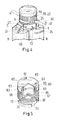
- Fig. 4 shows a perspective view of a first embodiment of a mounted on a double cartridge by means of bayonet closure Closure.
- the double cartridge contains two containers 8 and on the front side 6 of the cartridge segmental base elements 25, 27 are formed, which are stabilized by reinforcing ribs in the radial direction.
- the closure element 50 is fastened by means of bayonet tabs 30, 32 introduced into the segment-shaped groove 22 of the base elements 25, 27.
- the bayonet tabs 30, 32 are integrally formed on the closure element 50.
- the closure element 50 also has a coding nose 35, which in the illustrated, closed state, ie in the fully inserted into the base elements of the cartridge bayonet tabs 30, 32 of the closure element 50, aligned with the V-shaped notch 13 on the front side 6 of the cartridge.
- the closure element is largely covered by a safety cap 80, ie the safety cap extends in the closed state to the base elements 25, 27, so that only a lower, directed against the cartridge part of the closure element 50 containing the bayonet tabs 30, 32 and the coding nose 35 is exposed and visible from the outside.
- the fuse cap 80 has on its lateral surface a corrugation 85, which serves for easier handling of the fuse cap 80.
- the corrugation 85 consists of a number parallel to the longitudinal axis of the fuse cap 80 extending webs, wherein the webs are arranged circumferentially over the entire circumference of the safety cap. However, the length of the webs is shorter than the length of the lateral surface of the safety cap measured relative to the longitudinal axis of the safety cap, the corrugation extending as far as the lower edge of the safety cap 80 facing the cartridge.
- FIG. 5 shows a perspective view of the in Fig. 4 Shown in partially cutaway representation.
- the closure element 50 on the inside of the hollow cylindrical part 55 in the upper region, ie in the area facing away from the bayonet flanges, a circumferential locking groove 60, in which spring elements 90 of the fuse cap engage.
- fuse cap 80 has on its lid three recesses 61, 62, 63, on each of which a spring element 90 is formed.
- the locking groove 60 and the spring elements 90 together form a tongue and groove latch or a snap connection.
- the closure element 50 and the fuse cap 80 form a unit, wherein the fuse cap 80 in the mechanically unclaimed state, ie in the radially unpressurized state, relative to the closure member 50 is freely rotatable, the fuse cap 80, however, captive is connected to the closure element 50, that is, the closure consists of a closure element 50 and a thus securely locked, but rotatably mounted fuse cap 80th
- Fig. 5 shows, the closure element 50 on its lateral surface on a sawtooth structure 70, which consists of extending in the longitudinal direction of the closure member 50 ribs in sawtooth shape.
- the safety cap 80 has a sawtooth structure 75 corresponding thereto. As long as the safety cap 80 is not subjected to radial pressure, the sawtooth structures 70, 75 of the closure element 50 and the safety cap 80 do not intermesh, ie the inner diameter of the safety cap 80, including the sawtooth structure, is greater than the outer diameter of the closure element including the sawtooth structure.
- the safety cap 80 is made of elastic material, so that when a radial pressure a is exerted on the safety cap 80, the sawtooth structures 70, 75 of the closure element 50 and the safety cap 80 engage in one another and only then can the closure element 50 be rotated in direction b. Consequently, fixing as well as removing the closure 50, 80 from the cartridge 5 requires a radial pressure movement a as well as a corresponding rotational movement b (see FIG Fig. 4 ).
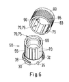
- FIG. 6 shows a perspective view of the closure element 50 and the matching fuse cap 80 of the in Fig. 5 Shutter shown.
- This in Fig. 6 Shuttering element 50 shown has at the lower end of its cylindrical portion 55, the segment-shaped bayonet tabs 30, 32, an outwardly open, V-shaped notch 38 as a coding means and one with a recess 23 (see Fig. 2 . Fig. 4 . Fig. 7 ) of the base element 25 of the double cartridge corresponding coding nose 35.
- the lateral surface of the cylindrical part 55 of the closure element 50 shows a sawtooth structure 70, this structure 70 consists of extending in the longitudinal direction of the closure element 50 ribs in sawtooth shape.
- the circumferential locking groove 60th In the upper area on the inside of the hollow cylindrical part 55 of the closure element 50 is the circumferential locking groove 60th
- Fig. 6 further shows a fuse cap 80 which is suitable for the closure element 50 and has a spring element 90 integrally formed on the cover of the safety cap 80.
- the inner wall of the hollow cylindrical part 83 of the safety cap 80 has a sawtooth structure 75 corresponding to the sawtooth structure 70 of the closure element 50.
- the lateral surface of the safety cap 80 also has a corrugation 85 for better handling.
- FIG. 7 shows a perspective view of a second embodiment of a fastened to a double cartridge by means of bayonet closure.
- the double cartridge contains two containers 8 each for receiving a chemical component.
- segmental base elements 25, 27 are formed, which are stabilized by reinforcing ribs 7 in the radial direction.
- the closure member 40 is cup-shaped or cap-shaped, with its exposed edge a in the 4 to 6 shown closure member 50 has corresponding flange structure, ie, the closure member 40 has segmental bayonet tabs 30, 32 and a coding nose 35, since Also, the closure element 40 of the second kind should fit on a commercial double cartridge with bayonet fixing.
- the closure element 40 can be fastened by means of bayonet lugs 30, 32 introduced into the segment-shaped groove 22 of the base elements 25, 27 of the discharge device 5.
- the bayonet tabs 30, 32 and the coding nose 35 are preferably integrally formed on the closure element 40.
- the coding nose 35 is aligned in the illustrated, closed state, ie in the fully inserted into the base elements of the cartridge bayonet tabs 30, 32, with the V-shaped notch 13 on the front side 6 of the cartridge.
- the closure element 40 is in turn largely covered by a safety cap 100, ie the safety cap extends in the closed state to the base elements 25, 27, so that only a lower, directed against the cartridge part of the closure element 40 containing the bayonet tabs 30, 32 and the coding nose 35 is exposed and visible from the outside.
- the safety cap 100 has on its cover element 105 a rotating bracket 110, which serves for easier handling of the safety cap 100.
- Fig. 8 shows a perspective view of the in Fig. 7 Shown in partially cutaway representation.
- Fig. 8 is at the upper part of the lateral surface of the cylindrical portion 45 of the closure member 40, ie on the bayonet attachment means side facing away from the lateral surface of the closure member 40, a circumferential groove visible, which is referred to as a locking groove 48 and is used to engage spring elements 120 of the fuse cap second type.
- fuse cap 100 has an exposed, peripheral edge, which is either designed as a total spring element 120, or a number, in particular three separate spring elements 120 has.
- the spring elements 120 are preferably designed as hook-shaped lugs such that each hook-shaped nose can engage in the optionally slightly undercut locking groove 48.
- the safety cap 100 can be put over the closure element 40 with the hook-shaped lugs, wherein in the end position, the hook-shaped lugs behind the circumferential locking groove 48, so that thereby securing the cap 100 captively attached to the closure member 40 is.
- the latching groove 48 and the spring elements 120 formed as hook-shaped lugs together form a tongue and groove catch 125 or a snap connection.
- the closure element 40 and the safety cap 100 form a unit, wherein the safety cap 100 in the mechanically unstressed condition, ie in an axially uniaxially in the direction of the longitudinal axis of the closure member 40 and the safety cap 100 not stressed state, compared to Locking element 40 is freely rotatable, the locking cap 100, however, is captively connected to the closure element 40, that is, the closure consists of a closure element 40 and a detent-locked, but rotatably mounted by the tongue-and-groove catch 125 fuse cap 100th
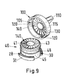
- FIG. 9 shows a perspective view of the closure element 40 and the matching fuse cap 100 of the in Fig. 8 Shutter shown.
- closure member 40 has at the lower end of its cylindrical portion 45, the segment-shaped bayonet tabs 30 and 32.
- the upper surface of the bayonet tabs may have a bevel 28, so that the initial insertion of the bayonet tabs 30, 32 is facilitated in the base elements 25 and 27 of the discharge.
- the lateral surface of the cylindrical part 45 of the closure element 40 has, on the one hand, the circumferential latching groove 48 and the lid region has a radially extending sawtooth structure 43.
- the sawtooth structure 43 on the cover outer side of the closure element 40 is formed by radially extending ribs in sawtooth shape, wherein the length of the ribs do not cover the entire radius of the lid portion, but only about 1/2 to 2/3 of the lid outer region (see Fig. 9 ).
- Fig. 9 further shows a securing cap 100 suitable for the closure element 40 with spring elements 120 integrally formed on the inner surface of the cylindrical part 115 of the closure element 40 in the region of the circumferential, free end.
- the inside of the lid part 105 of the safety cap 100 has a sawtooth structure 130 corresponding to the sawtooth structure 43 of the closure element consisting of radially extending ribs in sawtooth shape.
- the safety cap 100 shows a rotating bar 110, which serves to facilitate the handling of the closure.
- the closure element 40 and the safety cap 100 are designed such that in their mutually locked state with non-pressure-loaded safety cap, the closure element 40 and the safety cap 100 are freely rotatable, ie the sawtooth structures 43 and 130 do not interlock, ie the spring elements 120 have in the locking groove 48 a certain game on.
- an axial pressure a ie pressure in the direction of the discharge of the double cartridge on the fuse cap 100
- the two sawtooth structures 43 and 130 engage each other and thus form a SAge leopardkupplung 140.
Landscapes
- Engineering & Computer Science (AREA)
- Mechanical Engineering (AREA)
- Closures For Containers (AREA)
Abstract
Description
- Die Erfindung betrifft einen kindersicheren Verschluss für eine Austragsvorrichtung mit Bajonettbefestigungsmitteln im Sinne des Oberbegriffs von Anspruch 1.
- Austragsvorrichtungen und insbesondere Mehrfachkartuschen zum Mischen und Ausbringen von Mehrkomponentenmassen sind beispielsweise aus der
EP-A-0730913 bekannt. Dabei wird eine Verschlusskappe oder ein Mischerelement mittels eines Bajonettverschlusses an der Austragsvorrichtung befestigt. - In solchen Austragsvorrichtungen kommen vielfach Substanzen zur Anwendung, die chemisch mehr oder weniger aggressiv sind, und deren Einnahme oder Hautkontakt verhindert werden muss, da es ansonsten zu Vergiftungen oder Verätzungen von Personen oder Tieren kommen kann. Während Erwachsene im allgemeinen den korrekten Umgang mit derartigen Substanzen beherrschen, besteht insbesondere bei Kindern die Gefahr, dass sie den Inhalt der Austragsvorrichtung für etwas geniessbares halten und einnehmen.
- Aufgabe vorliegender Erfindung ist es, einen kindersicheren Verschluss für eine Austragsvorrichtung mit Bajonettbefestigungsmitteln vorzuschlagen, welcher insbesondere Kinder vor einem unbefugten Zugriff zu derartigen, in der Austragsvorrichtung vorhandenen Substanzen schützt.
- Diese Aufgabe wird durch eine Austragsvorrichtung mit den Merkmalen des Anspruchs 1 gelöst. Vorteilhafte Ausgestaltungen und zweckmässige Weiterbildungen der Erfindung sind in den Unteransprüchen angegeben.
- Der erfindungsgemässe Verschluss verlangt zum Öffnen der Austragsvorrichtung die Koordination verschiedener Bewegungsabläufe mit zusätzlichem Kraftaufwand, was für Kinder, insbesondere Kleinkinder, nicht zu bewerkstelligen ist. Infolgedessen ist der vorgeschlagene Verschluss kindersicher.
- Der kindersichere Verschluss eignet sich insbesondere für eine Mehrkomponentenkartusche enthaltend eine Mehrzahl von zylinderförmigen Behältern. Bevorzugt eignet sich der kindersichere Verschluss für eine Doppelkartusche zum Austragen zweier Komponenten. Die Behälter enthalten bevorzugt zylinderförmige Kammern. Die Kammern, d.h. der Innenraum der hohlzylinderförmigen Kartuschen-Behälter, können kreiszylinderförmig ausgebildet sein oder einen elliptischen oder polygonalen Querschnitt aufweisen. Zur Mehrkomponentenkartusche gehört auch ein Ausdrückstössel, welcher für jede Kammer einen formschlüssigen Kolben aufweist.
- Die Mehrkomponentenkartuschen beinhalten neben den zylinderförmigen Kammern auch eine als Auslassteil dienende Anformung. Dabei betrifft der Auslassteil beispielsweise eine Gesamtheit von rohrförmigen Anformungen der einzelnen Kammern und/oder ein zylindrisches Anschlussteil. Das Auslassteil ist vom Verschluss übergreifbar und weist verschlussseitig für jede Komponente eine Ausgabeöffnung auf, d.h. die einzelnen Komponenten werden bis zum verschlussseitigen Ende des Auslassteils voneinander getrennt gehalten, so dass eine vorzeitige Vermischung der Komponenten verhindert wird.
- Der Auslassteil der Mehrkomponentenkartusche enthält beispielsweise erste Bajonettbefestigungsmittel. Der Verschluss enthält damit korrespondierende, zweite Bajonettbefestigungsmittel. Eines der zwei Befestigungsmittel weist Bajonettlaschen auf, welche in entsprechende Sockelelemente des anderen Bajonettbefestigungsmittels einführbar sind. Zweckmässigerweise weisen beide Bajonettbefestigungsmittel auch Codierelemente für eine vorgegebene Ausrichtung des Verschlusses und der Austragvorrichtung oder Mehrkomponentenkartusche auf.
- Der erfindungsgemässe, kindersichere Verschluss weist nun ein Verschlusselement mit ersten Eingriffselementen und eine das Verschlusselement wenigstens teilweise überdeckende Sicherungskappe mit zweiten Eingriffselementen auf. Zudem enthalten die Sicherungskappe und das Verschlusselement Formschlusselemente, welche das trennfeste Verbinden des Verschlusselements und der Sicherungskappe derart erlauben, dass das Verschlusselement und die Sicherungskappe gegeneinander frei drehbar gelagert bleiben, solange das Sicherungselement gegenüber dem Verschlusselement druckfrei bleibt, d.h. solange auf die Sicherungskappe kein mechanischer Druck von Aussen ausgeübt wird. Die Sicherungskappe ist zumindest teilweise derart elastisch verformbar ausgebildet, dass die ersten und zweiten Eingriffselemente durch Pressen der Sicherungskappe gegen das Verschlusselement miteinander in Eingriff bringbar sind.
- Die Sicherungskappe stellt bevorzugt ein becher- oder kappenförmiges Element dar, welches dergestalt ausgebildet ist, dass es über das Verschlusselement stülpbar ist. Dabei sind das Verschlusselement und die Sicherungskappe bevorzugt hohlzylinderförmige Elemente mit einem Boden oder Deckel, wobei die Sicherungskappe einen grösseren Querschnitt aufweist als das Verschlusselement, so dass die Sicherungskappe mit ihrem hohlzylinderförmigen Teil über den hohlzylinderförmigen Teil des Verschlusselements stülpbar ist.
- Das Verschlusselement ist bevorzugt ein becherförmiges Element mit einem hohlzylinderförmigen Teil und einem Boden, wobei das Verschlusselement an seiner Mantelfläche, d.h. an der Aussenseite des hohlzylinderförmigen Teils, oder an der Aussenseite des Bodens erste Eingriffselemente aufweist.
- Die Sicherungskappe ist bevorzugt ein über das Verschlusselement stülpbares, ebenfalls becher- oder hutförmiges Element mit einem hohlzylinderförmigen Teil und einem Boden, wobei die Sicherungskappe bevorzugt auf seiner Innenseite, d.h. auf der Innenseite des hohlzylinderförmigen Teils oder auf der Boden-Innenseite, zweite Eingriffselemente aufweist.
- Die Sicherungskappe ist dergestalt dimensioniert, dass die über das Verschlusselement gestülpte Sicherungskappe im mechanisch nicht beanspruchten Zustand gegenüber dem Verschlusselement frei drehbar ist, d.h. die ersten und zweiten Eingriffselemente nicht miteinander im Eingriff stehen. Hierbei bedeutet der Ausdruck "im mechanisch nicht beanspruchten Zustand", dass auf die über das Verschlusselement gestülpte Sicherungskappe keine äussere Kraft ausgeübt wird, wie dies beispielsweise durch Zusammendrücken der Kappe oder durch Aufdrücken oder Aufpressen der Sicherungskappe auf das Verschlusselement geschehen könnte.
- Die Eingriffselemente am Verschlusselement wie auch an der Sicherungskappe bestehen bevorzugt aus einer Sägezahnstruktur, d.h. Rippen mit einer Sägezahnform. Demnach beschreiben die Eingriffselemente des Verschlusselements und der Sicherungskappe zusammen bevorzugt eine Sägezahnkupplung.
- Die Sicherungskappe soll unverlierbar, jedoch im drucklosen Zustand frei drehbar an das Verschlusselement festlegbar sein. Dies geschieht bevorzugt durch Verwendung von Nut-Feder-Verbindungselementen. Dazu weist das Verschlusselement beispielsweise eine zu seiner konzentrischen Längsachse quer verlaufende, umlaufende oder sektorförmige Nut auf, und die Sicherungskappe weist beispielsweise ein elastisch in die Nut des Verschlusselements eingreifbares, an die Sicherungskappe angeformtes Federelement auf. Andererseits kann auch die Sicherungskappe eine zu seiner konzentrischen Längsachse quer verlaufende, umlaufende oder sektorförmige Nut aufweisen, wobei dann das Verschlusselement wenigstens ein elastisch in die Nut der Sicherungskappe eingreifbares, an das Verschlusselement angeformtes Federelement aufweist.
- Die Sockelelemente der Austragsvorrichtung oder des Verschlusselementes stellen beispielsweise ring- oder sektorförmige Elemente mit gegebenenfalls einer Hinterschneidung dar. Die ring- oder sektorförmigen Elemente dienen so zur wenigstens teilweisen formschlüssigen Aufnahme der Bajonettlaschen.
- Die Aussparungen an den Sockelelementen, d.h. der zwischen zwei segmentförmigen Sockelelementen befindliche freie Raum, sowie entsprechend gestaltete Bajonettlaschen unterschiedlicher Breite dienen zusammen bevorzugt als Codierelemente. Diese sind dann derart ausgebildet, dass die Bajonettlaschen des Verschlusselementes bzw. der Austragsvorrichtung bezüglich der Aussparungen der ring- oder sektorförmigen Sockelelemente in nur einer bestimmten Stellung einführbar sind.
- Die Sockelelemente und die Austragsvorrichtung sind bevorzugt einstückig ausgebildet, zweckmässigerweise in Form eines gegossenen Formkörpers. Die Bajonettlaschen sind ebenfalls bevorzugt einstückig in der Gestalt eines gegossenen Formkörpers an das Verschlusselement angeformt. Alternativ können auch die Sockelelemente mit dem Verschlusselement einstückig in der Gestalt eines gegossenen Formkörpers ausgebildet sein, und die Bajonettlaschen einstückig als Gusskörperelement an die Austragsvorrichtung angeformt sein.
- Ganz bevorzugt stellt das Verschlusselement ein zylinderförmiges Element dar, welches zumindest an einem Teil seiner Mantelfläche eine parallel zu seiner konzentrischen Längsachse verlaufende Sägezahnstruktur aufweist, wobei die Sicherungskappe als becherförmiges Element mit einem hohlzylinderförmigen Teil und einem Boden ausgebildet ist, und die Innenseite des becherförmigen Elements eine parallel zu seiner konzentrischen Längsachse verlaufende, in die Sägezahnstruktur des Verschlusselements eingreifbare Sägezahnstruktur aufweist. Dabei weist das Verschlusselement an dem gegen die Austragsvorrichtung gerichteten Rand seiner Mantelfläche quer zu seiner konzentrischen Längsachse, radial abstehende, segmentförmige Bajonettlaschen auf.
- In einer weiteren bevorzugten Ausführungsform ist das Verschlusselement ein becherförmiges Element mit einem hohlzylinderförmigen Teil und einem Boden, welches zumindest an einem Teil seiner Boden-Aussenfläche eine radial nach aussen verlaufende Sägezahnstruktur aufweist, und die Sicherungskappe ebenfalls ein becherförmiges Element mit einem hohlzylinderförmigen Teil und einem Boden darstellt, wobei die Innenseite des Bodens der Sicherungskappe radial eine nach aussen verlaufende, in die Sägezahnstruktur des Verschlusselementes eingreifbare Sägezahnstruktur aufweist. Dabei weist das Verschlusselement an dem gegen die Austragsvorrichtung gerichteten Rand seiner Mantelfläche quer zu seiner konzentrischen Längsachse, wiederum radial abstehende, segmentförmige Bajonettlaschen auf.
- Weiter bevorzugt sind an der Austragvorrichtung oder am Verschlusselement parallel zur Längsachse des Verschlusselements verlaufende, über den Bajonettlaschen angeordnete Anschlagflanken als Drehbegrenzung der beiden Bajonettbefestigungsmittel vorhanden.
- Der erfindungsgemässe Verschluss kann eine Kappe zum Verschluss einer Austragsvorrichtung darstellen, kann aber auch ein Mischerelement, insbesondere ein statisches Mischerelement aufweisen, welches in fluide Verbindung mit dem Inhalt der Austragsvorrichtung bringbar ist, wobei das Mischerelement das Verschlusselement und die Sicherungskappe durchstösst, wobei weiter das Verschlusselement und die Sicherungskappe gegenüber dem Mischer frei drehbar, jedoch abdichtend ausgebildet sind.
- Die Erfindung wird im Weiteren durch folgende Figuren beispielhaft weiter erläutert. Es zeigen
- Fig. 1
- einen Längsschnitt einer Doppelkartusche;
- Fig. 2
- Eine Draufsicht der Kartusche nach
Fig. 1 ; - Fig. 3
- eine Draufsicht auf die zweiten Bajonettbefestigungsmittel des Verschlusselements;
- Fig. 4
- eine perspektivische Ansicht einer ersten Ausführungsform eines auf eine Doppelkartusche mittels Bajonettverschluss befestigten Verschlusses;
- Fig. 5
- eine perspektivische Ansicht des in
Fig. 4 dargestellten Verschlusses in teilweise aufgeschnittener Darstellung; - Fig. 6
- eine perspektivische Darstellung des Verschlusselements und der dazu passenden Sicherungskappe des in
Fig. 5 gezeigten Verschlusses; - Fig. 7
- eine perspektivische Ansicht einer zweiten Ausführungsform eines auf eine Doppelkartusche mittels Bajonettverschluss befestigten Verschlusses;
- Fig. 8
- eine perspektivische Ansicht des in
Fig. 7 dargestellten Verschlusses in teilweise aufgeschnittener Darstellung; - Fig. 9
- eine perspektivische Darstellung des Verschlusselements und der dazu passenden Sicherungskappe des in
Fig. 8 gezeigten Verschlusses. -
Fig. 1 zeigt einen Längsschnitt durch eine als Doppelkartusche ausgebildete Austragsvorrichtung 5, welche zwei zylindrische Behälter gleicher Querschnittsfläche für ein Dosierverhältnis 1 : 1 aufweist. Die Behälter 8 münden in zwei getrennte, zylindrische und voneinander beabstandete Auslässe 9 und 10. Falls ein statischer Zweikomponenten-Mischer an die Austragsvorrichtung angeschlossen wird, passen die Auslässe 9, 10 der Austragsvorrichtung derart in oder auf die Einlässe des Mischers, dass sich eine dichte Verbindung ergibt. Die Austragsvorrichtung 5 weist zudem erste Bajonettbefestigungsmittel 20 in Form von Sockelelementen 25, 27 auf. Die Sockelelemente beschreiben eine um die Auslässe 9, 10 verlaufende ring-oder segmentförmige Nut 22 zur Aufnahme zweiter Bajonettbefestigungsmittel. -
Fig. 2 zeigt eine Draufsicht auf die inFig. 1 dargestellte Austragsvorrichtung 5 mit zwei zylindrischen Behältern 8 gleichen Querschnitts. Die Vorderseite 6 der Austragsvorrichtung 5 weist neben den Auslässen 9, 10 zwei einander gegenüberliegende, segmentförmige Sockelelemente 25 und 27 auf, wobei das Segment 25 etwas breiter ist als das Segment 27. Die segmentförmigen Sockelelemente 25, 27 weisen entsprechend segmentförmige Nuten 22 auf (sieheFig. 1 ), welche der Aufnahme von Bajonettlaschen 30, 32 des Verschlusselementes 50 dienen (sieheFig. 3 undFig. 4 ). Die Sockelelemente 25, 27 sind durch Verstärkungsrippen 7 verstärkt. Die Vorderseite 6 der Austragsvorrichtung 5 weist zudem eine V-förmige Kerbe 13 als visuelles Codiermittel auf. Das segmentförmige Sockelelement 25 enthält eine radial nach innen geöffnete V-förmige Ausnehmung 23, welche mit einer an das Verschlusselement angeformten Codiernase 35 (sieheFig. 3 ) kooperieren kann, so dass das Verschlusselement 50 nur in eine Richtung eingesetzt werden kann, was insbesondere bei einem Verschluss mit integriertem Mischer von Bedeutung ist. Die als Doppelkartusche ausgebildete Austragsvorrichtung 5 mit den zwei Behältern 8, den Auslässen 9 und 10, den segmentförmigen Sockelelementen 25 und 27 sowie den Verstärkungsrippen 7 bilden zusammen bevorzugt ein Kunststoff-Gussteil, insbesondere ein Spritzgussteil. -
Fig. 3 zeigt eine Draufsicht auf die zweiten Bajonettbefestigungsmittel eines Verschlusselements 50 sowie auf den zylinderförmigen Teil 55 des Verschlusselements 50. Das Verschlusselement 50 weist zwei segmentförmige Bajonettlaschen 30 und 32 auf. Die Bajonettlasche 30 enthält zudem eine nach aussen geöffnete, V-förmige Kerbe 38 als Codiermittel, welche beispielsweise mit der Kerbe 13 der Austragsvorrichtung 5 korrespondiert, so dass bei einem in die Sockelelemente der Austragsvorrichtung 5 eingeschobenen, jedoch nicht eingerasteten Verschlusselement die Kerben 13 und 38 beispielsweise übereinanderliegen. - Das Verschlusselement 50 enthält an seinem zylinderförmigen Teil 55 eine angeformte Codiernase 35, welche zum Einführen des Verschlusses in den Bajonettsockel 25, 27 der Austragsvorrichtung 5 mit der V-förmigen Ausnehmung 23 des Sockelelements 25 korrespondiert. Weiter kann die Kerbe 13 der Austragsvorrichtung 5 bei einem in die Sockelelemente der Austragsvorrichtung 5 vollständig eingerasteten Verschlusselement 50 mit der Codiernase 35 korrespondieren, d.h. die Codiernase 35 und die Kerbe 13 liegen dann übereinander. Die Bajonettlaschen 30, 32 und die Codiernase 35 sind bevorzugt einstückig mit dem becherförmigen Verschlusselement 50 geformt, so dass das Verschlusselement inkl. Bajonettlaschen und Codiernase bevorzugt ein Gussteil, insbesondere ein Kunststoff-Spitzgussteil, darstellt.
-
Fig. 4 zeigt eine perspektivische Ansicht einer ersten Ausführungsform eines auf eine Doppelkartusche mittels Bajonettverschluss befestigten Verschlusses. Die Doppelkartusche enthält zwei Behälter 8 und auf der Vorderseite 6 der Kartusche sind segmentförmige Sockelelemente 25, 27 angeformt, welche durch Verstärkungsrippen in radialer Richtung stabilisiert werden. Das Verschlusselement 50 ist mittels in die segmentförmige Nut 22 der Sockelelemente 25, 27 eingeführte Bajonettlaschen 30, 32 befestigt. Die Bajonettlaschen 30, 32 sind einstückig an das Verschlusselement 50 angeformt. Das Verschlusselement 50 weist zudem eine Codiernase 35 auf, welche im dargestellten, geschlossenen Zustand, d.h. bei den vollständig in die Sockelelemente der Kartusche eingeschobenen Bajonettlaschen 30, 32 des Verschlusselements 50, mit der V-förmigen Kerbe 13 auf der Vorderseite 6 der Kartusche fluchtet. Das Verschlusselement wird grösstenteils durch eine Sicherungskappe 80 überdeckt, d.h. die Sicherungskappe reicht im geschlossenen Zustand bis an die Sockelelemente 25, 27, so dass nur ein unterer, gegen die Kartusche gerichteter Teil des Verschlusselements 50 enthaltend die Bajonettlaschen 30, 32 und die Codiernase 35 freiliegt und von aussen betrachtet sichtbar ist. Die Sicherungskappe 80 weist an ihrer Mantelfläche eine Riffelung 85 auf, welche zur einfacheren Handhabung der Sicherungskappe 80 dient. Die Riffelung 85 besteht aus einer Anzahl parallel zur Längsachse der Sicherungskappe 80 verlaufender Stege, wobei die Stege über den ganzen Umfang der Sicherungskappe umlaufend angeordnet sind. Die Länge der Stege ist jedoch kürzer als die zur Längsachse der Sicherungskappe gemessene Länge der Mantelfläche der Sicherungskappe, wobei die Riffelung bis an den unteren, gegen die Kartusche gerichteten Rand der Sicherungskappe 80 reicht. -
Figur 5 zeigt eine perspektivische Ansicht des inFig. 4 dargestellten Verschlusses in teilweise aufgeschnittener Darstellung. InFig. 5 ist klar ersichtlich, dass das Verschlusselement 50 an der Innenseite des hohlzylinderförmigen Teils 55 im oberen Bereich, d.h. im den Bajonettflanschen abgekehrten Bereich, eine umlaufende Rastnut 60 aufweist, in welche Federelemente 90 der Sicherungskappe eingreifen. Die inFig. 5 dargestellte Sicherungskappe 80 weist an ihrem Deckel drei Ausnehmungen 61, 62, 63 auf, an denen je ein Federelement 90 angeformt ist. Die Rastnut 60 und die Federelemente 90 bilden zusammen eine Nut-Feder Verrastung oder eine Schnappverbindung. Durch die Nut-Feder Verrastungselemente 60, 90 bilden das Verschlusselement 50 und die Sicherungskappe 80 eine Einheit, wobei die Sicherungskappe 80 im mechanisch nicht beanspruchten Zustand, d.h. im radial nicht druckbeanspruchten Zustand, gegenüber dem Verschlusselement 50 frei drehbar ist, die Sicherungskappe 80 jedoch unverlierbar mit dem Verschlusselement 50 verbunden ist, d.h. der Verschluss besteht aus einem Verschlusselement 50 und einer damit trennfest verrasteten, jedoch drehbar gelagerten Sicherungskappe 80. - Wie aus
Fig. 5 hervorgeht, weist das Verschlusselement 50 an seiner Mantelfläche eine Sägezahnstruktur 70 auf, welche aus in Längsrichtung des Verschlusselements 50 verlaufende Rippen in Sägezahnform besteht. Die Sicherungskappe 80 weist eine dazu korrespondierende Sägezahnstruktur 75 auf. Solange die Sicherungskappe 80 radial nicht druckbeansprucht ist, greifen die Sägezahnstrukturen 70, 75 des Verschlusselements 50 und der Sicherungskappe 80 nicht ineinander, d.h. der Innendurchmesser der Sicherungskappe 80 inkl. Sägezahnstruktur ist grösser als der Aussendurchmesser des Verschlusselements inkl. Sägezahnstruktur. Die Sicherungskappe 80 ist aus elastischem Material gefertigt, so dass beim Ausüben eines radialen Druckes a auf die Sicherungskappe 80 die Sägezahnstrukturen 70, 75 des Verschlusselements 50 und der Sicherungskappe 80 ineinandergreifen und erst dadurch das Verschlusselement 50 in Richtung b gedreht werden kann. Demzufolge benötigt das Festlegen an wie auch das Wegnehmen des Verschlusses 50, 80 von der Kartusche 5 eine radiale Druckbewegung a wie auch eine entsprechende Drehbewegung b (sieheFig. 4 ). -
Figur 6 zeigt eine perspektivische Darstellung des Verschlusselements 50 und der dazu passenden Sicherungskappe 80 des inFig. 5 gezeigten Verschlusses. Das inFig. 6 gezeigte Verschlusselement 50 weist am unteren Ende seines zylinderförmigen Teils 55 die segmentförmigen Bajonettlaschen 30, 32, eine nach aussen geöffnete, V-förmige Kerbe 38 als Codiermittel sowie eine mit einer Ausnehmung 23 (sieheFig. 2 ,Fig. 4 ,Fig. 7 ) des Sockelelements 25 der Doppelkartusche korrespondierende Codiernase 35 auf. Die Mantelfläche des zylindrischen Teils 55 des Verschlusselements 50 zeigt eine Sägezahnstruktur 70, wobei diese Struktur 70 aus in Längsrichtung des Verschlusselements 50 verlaufenden Rippen in Sägezahnform besteht. Im oberen Bereich an der Innenseite des hohlzylinderförmigen Teils 55 des Verschlusselements 50 befindet sich die umlaufende Rastnut 60. -
Fig. 6 zeigt weiter eine zum Verschlusselement 50 passende Sicherungskappe 80 mit einem am Deckel der Sicherungskappe 80 angeformten Federelement 90. Die Innenwand des hohlzylinderförmigen Teils 83 der Sicherungskappe 80 weist eine zur Sägezahnstruktur 70 des Verschlusselements 50 korrespondierende Sägezahnstruktur 75 auf. Die Mantelfläche der Sicherungskappe 80 weist zudem eine Riffelung 85 zur besseren Handhabung auf. -
Figur 7 zeigt eine perspektivische Ansicht einer zweiten Ausführungsform eines auf eine Doppelkartusche mittels Bajonettverschluss befestigten Verschlusses. Die Doppelkartusche enthält zwei Behälter 8 zur Aufnahme je einer chemischen Komponente. Auf der Vorderseite 6 der Kartusche sind segmentförmige Sockelelemente 25, 27 angeformt, welche durch Verstärkungsrippen 7 in radialer Richtung stabilisiert sind. Das Verschlusselement 40 ist tassen- oder kappenförmig aufgebaut, wobei sein frei liegender Rand eine dem inFig. 4 bis 6 gezeigten Verschlusselement 50 entsprechende Flanschstruktur aufweist, d.h. auch das Verschlusselement 40 weist segmentförmige Bajonettlaschen 30, 32 und eine Codiernase 35 auf, da auch das Verschlusselement 40 zweiter Art auf eine handelsübliche Doppelkartusche mit Bajonettbefestigungsmittel passen soll. Folglich ist das Verschlusselement 40 mittels in die segmentförmige Nut 22 der Sockelelemente 25, 27 der Austragsvorrichtung 5 eingeführte Bajonettlaschen 30, 32 befestigbar. Die Bajonettlaschen 30, 32 und die Codiernase 35 sind bevorzugt einstückig an das Verschlusselement 40 angeformt. Die Codiernase 35 fluchtet im dargestellten, geschlossenen Zustand, d.h. bei den vollständig in die Sockelelemente der Kartusche eingeschobenen Bajonettlaschen 30, 32, mit der V-förmigen Kerbe 13 auf der Vorderseite 6 der Kartusche. Das Verschlusselement 40 wird wiederum grösstenteils durch eine Sicherungskappe 100 überdeckt, d.h. die Sicherungskappe reicht im geschlossenen Zustand bis an die Sockelelemente 25, 27, so dass nur ein unterer, gegen die Kartusche gerichteter Teil des Verschlusselements 40 enthaltend die Bajonettlaschen 30, 32 und die Codiernase 35 freiliegt und von aussen sichtbar ist. Die Sicherungskappe 100 weist an ihrem Deckelelement 105 einen Drehbügel 110 auf, welcher zur einfacheren Handhabung der Sicherungskappe 100 dient. -
Fig. 8 zeigt eine perspektivische Ansicht des inFig. 7 dargestellten Verschlusses in teilweise aufgeschnittener Darstellung. InFig. 8 ist am oberen Teil der Mantelfläche des zylindrischen Teils 45 des Verschlusselements 40, d.h. an der den Bajonettbefestigungsmittel abgekehrten Seite der Mantelfläche des Verschlusselements 40, eine umlaufende Nut sichtbar, welche als Rastnut 48 bezeichnet wird und zum Eingriff von Federelementen 120 der Sicherungskappe zweiter Art dient. Die inFig. 8 gezeigte Sicherungskappe 100 weist einen frei liegenden, umlaufenden Rand auf, welcher entweder insgesamt als Federelement 120 ausgebildet ist, oder eine Anzahl, insbesondere drei getrennte Federelemente 120 aufweist. Die Federelemente 120 sind bevorzugt als hakenförmige Nasen derart ausgebildet, dass jede hakenförmige Nase in die gegebenenfalls leicht hinterschnittene Rastnut 48 eingreifen können. Da die Sicherungskappe und insbesondere ihr freiliegender Rand wenigstens teilweise elastisch ausgebildet ist, lässt sich die Sicherungskappe 100 mit den hakenförmigen Nasen über das Verschlusselement 40 stülpen, wobei in der Endstellung die hakenförmigen Nasen hinter die umlaufende Rastnut 48 greifen, so dass dadurch die Sicherungskappe 100 unverlierbar am Verschlusselement 40 befestigt ist. Die Rastnut 48 und die als hakenförmige Nasen ausgebildeten Federelemente 120 bilden zusammen eine Nut-Feder-Verrastung 125 oder eine Schnappverbindung. Durch die Nut-Feder-Verrastung 125 bilden das Verschlusselement 40 und die Sicherungskappe 100 eine Einheit, wobei die Sicherungskappe 100 im mechanisch nicht beanspruchten Zustand, d.h. in einem axial in Richtung der Längsachse des Verschlusselements 40 und der Sicherungskappe 100 nicht druckbeanspruchten Zustand, gegenüber dem Verschlusselement 40 frei drehbar ist, die Sicherungskappe 100 jedoch unverlierbar mit dem Verschlusselement 40 verbunden ist, d.h. der Verschluss besteht aus einem Verschlusselement 40 und einer damit trennfest verrasteten, jedoch durch die Nut-Feder-Verrastung 125 drehbar gelagerten Sicherungskappe 100. - Aus
Fig. 8 ist auch klar ersichtlich, dass der Drehbügel 110 der Sicherungskappe 100 wie auch die an die Sicherungskappe 100 angeformten Federelemente 120 mit der Sicherungskappe eine Einheit bilden, d.h. ein Gussstück bilden, welches bevorzugt ein Kunststoff-Gusselement darstellt. -
Figur 9 zeigt eine perspektivische Darstellung des Verschlusselements 40 und der dazu passenden Sicherungskappe 100 des inFig. 8 gezeigten Verschlusses. - Das in
Fig. 9 gezeigte Verschlusselement 40 weist am unteren Ende seines zylinderförmigen Teils 45 die segmentförmigen Bajonettlaschen 30 und 32 auf. Die obere Fläche der Bajonettlaschen kann dabei eine Anschrägung 28 aufweisen, damit das anfängliche Einführen der Bajonettlaschen 30, 32 in die Sockelelemente 25 und 27 der Austragsvorrichtung erleichtert wird. - Die Mantelfläche des zylindrischen Teils 45 des Verschlusselements 40 weist einerseits die umlaufende Rastnut 48 und der Deckelbereich eine radial verlaufende Sägezahnstruktur 43 auf. Die Sägezahnstruktur 43 an der Deckelaussenseite des Verschlusselementes 40 wird durch radial verlaufende Rippen in Sägezahnform gebildet, wobei die Länge der Rippen nicht den ganzen Radius des Deckelbereichs umfassen, sondern nur etwa 1/2 bis 2/3 des Deckel-Aussenbereichs (siehe
Fig. 9 ). -
Fig. 9 zeigt weiter eine zum Verschlusselement 40 passende Sicherungskappe 100 mit an der Innenfläche des zylindrischen Teils 115 des Verschlusselementes 40, im Bereich des umlaufenden, freien Endes angeformten Federelementen 120. Die Innenseite des Deckelteils 105 der Sicherungskappe 100 weist eine zur Sägezahnstruktur 43 des Verschlusselements korrespondierende Sägezahnstruktur 130 bestehend aus radial verlaufenden Rippen in Sägezahnform auf. Weiter zeigt die Sicherungskappe 100 einen Drehbügel 110, welcher der einfacheren Handhabung des Verschlusses dient. - Das Verschlusselement 40 und die Sicherungskappe 100 sind derart ausgebildet, dass in ihrem gegenseitig verrasteten Zustand bei nicht druckbeanspruchter Sicherungskappe das Verschlusselement 40 und die Sicherungskappe 100 frei drehbar sind, d.h. die Sägezahnstrukturen 43 und 130 greifen nicht ineinander, d.h. die Federelemente 120 weisen in der Rastnut 48 ein gewisses Spiel auf. Beim Ausüben eines axialen Druckes a, d.h. Druck in Richtung der Austragsvorrichtung der Doppelkartusche, auf die Sicherungskappe 100 greifen die beiden Sägezahnstrukturen 43 und 130 ineinander und bilden somit eine Sägezahnkupplung 140. Im verzahnten Zustand lässt sich durch Drehen der Sicherungskappe 100 in Richtung b auch das Verschlusselement 40 mitdrehen, so dass der aus Verschlusselement 40 und Sicherungskappe 100 bestehende Verschluss aus den Sockelelementen 30, 32 der Austragsvorrichtung 5 heraus oder hereindrehen lässt. Demzufolge benötigt das Festlegen an wie auch das Wegnehmen des Verschlusses von der Doppelkartusche 5 eine axiale Druckbewegung a wie auch eine entsprechende Drehbewegung b.
Claims (17)
- Kindersicherer Verschluss für eine Austragvorrichtung (5) mit ersten Bajonettbefestigungsmitteln (20), wobei der Verschluss (40, 50, 80, 100) zweite Bajonettbefestigungsmittel (21) aufweist, und eines der zwei Bajonettbefestigungsmittel (20, 21) Bajonettlaschen (30, 32) aufweist, welche in entsprechende Sockelelemente (25, 27) des anderen Bajonettbefestigungsmittels (20, 21) einführbar sind, und beide Bajonettbefestigungsmittel (20, 21) Codierelemente (13, 23, 35, 38) für eine vorgegebene Ausrichtung des Verschlusses (40, 50, 80, 100) und der Austragvorrichtung (5) aufweisen,
dadurch gekennzeichnet, dass
der Verschluss (40, 50, 80, 100) ein Verschlusselement (40, 50) mit ersten Eingriffselementen (43, 70) und eine das Verschlusselement (40, 50) wenigstens teilweise überdeckende Sicherungskappe (80, 100) mit zweiten Eingriffselementen (75, 130) aufweist, die Sicherungskappe (80, 100) und das Verschlusselement (40, 50) mittels Formschlusselementen (58, 60, 90, 120) trennfest, jedoch gegeneinander drehbar verbunden sind, und die Sicherungskappe (80, 100) zumindest teilweise derart elastisch verformbar ausgebildet ist, dass die ersten und zweiten Eingriffselemente (43, 70, 75, 130) durch Pressen der Sicherungskappe (80, 100) gegen das Verschlusselement (40, 50) miteinander in Eingriff bringbar sind, wobei die Formschlusselemente (48, 60, 90, 100) des Verschlusselementes (40, 50) und der Sicherungskappe (80, 100) Nut-Feder-Verbindungselemente sind. - Kindersicherer Verschluss nach Anspruch 1, dadurch gekennzeichnet, dass die Sicherungskappe (80, 100) ein becherförmiges Element darstellt, welches dergestalt ausgebildet ist, dass es über das Verschlusselement (40, 50) stülpbar ist.
- Kindersicherer Verschluss nach Anspruch 1 oder 2, dadurch gekennzeichnet, dass das Verschlusselement (40, 50) ein becherförmiges Element mit einem hohlzylinderförmigen Teil (45, 55) und einem Boden (41, 57) ist, wobei das Verschlusselement (40, 50) an seiner Mantelfläche (55) oder an der Aussenseite des Bodens (41) erste Eingriffselemente (43, 70) aufweist.
- Kindersicherer Verschluss nach einem der Ansprüche 1 bis 3, dadurch gekennzeichnet, dass die Sicherungskappe (80, 100) ein über das Verschlusselement (40, 50) stülpbares, becherförmiges Element mit einem hohlzylinderförmigen Teil und einem Boden ist, wobei die Sicherungskappe (80, 100) auf seiner Innenseite zweite Eingriffselemente (75, 130) aufweist.
- Kindersicherer Verschluss nach einem der Ansprüche 1 bis 4, dadurch gekennzeichnet, dass die Sicherungskappe (80, 100) dergestalt dimensioniert ist, dass die über das Verschlusselement (40, 50) gestülpte Sicherungskappe (80, 100) im mechanisch nicht beanspruchten Zustand gegenüber dem Verschlusselement (40, 50) frei drehbar ist.
- Kindersicherer Verschluss nach einem der Ansprüche 1 bis 5, dadurch gekennzeichnet, dass die Eingriffselemente (43, 70, 75, 130) eine Sägezahnstruktur aufweisen.
- Kindersicherer Verschluss nach Anspruch 1, dadurch gekennzeichnet, dass das Verschlusselement (40, 50) eine zu seiner konzentrischen Längsachse quer verlaufende, umlaufende oder sektorförmige Rastnut (48, 60) aufweist, und die Sicherungskappe (80, 100) wenigstens ein elastisch in die Rastnut (48, 60) des Verschlusselementes (40, 50) eingreifbares, an die Sicherungskappe (80, 100) angeformtes Federelement (90, 120) aufweist.
- Kindersicherer Verschluss nach Anspruch 1, dadurch gekennzeichnet, dass die Sicherungskappe (80, 100) eine zu seiner konzentrischen Längsachse quer verlaufende, umlaufende oder sektorförmige Nut aufweist, und das Verschlusselement (40, 50) wenigstens ein elastisch in die Nut der Sicherungskappe eingreifbares, an das Verschlusselement (40, 50) angeformtes Federelement aufweist.
- Kindersicherer Verschluss nach einem der Ansprüche 1 bis 8, dadurch gekennzeichnet, dass die Austragvorrichtung (5) eine Mehrkomponentenkartusche ist, insbesondere eine Zweikomponentenkartusche.
- Kindersicherer Verschluss nach einem der Ansprüche 1 bis 9, dadurch gekennzeichnet, dass die Sockelelemente (25, 27) ring- oder sektorförmige Elemente mit einer Hinterschneidung zur wenigstens teilweisen formschlüssigen Aufnahme der Bajonettlaschen (30, 32) darstellen.
- Kindersicherer Verschluss nach Anspruch 10, dadurch gekennzeichnet, dass die Codierelemente durch Aussparungen an den Sockelelementen (25, 27) und Bajonettlaschen 30, 32 unterschiedlicher Breite derart gebildet sind, dass die Bajonettlaschen (30, 32) des Verschlusselementes (40, 50) bzw. der Austragsvorrichtung (5) bezüglich der Aussparungen der ring- oder sektorförmigen Sockelelemente (25, 27) in nur einer bestimmten Stellung einführbar sind.
- Kindersicherer Verschluss nach einem der Ansprüche 1 bis 11, dadurch gekennzeichnet, dass die Sockelelemente (25, 27) und die Austragsvorrichtung (5) einstückig in der Gestalt eines gegossenen Formkörpers ausgebildet sind, und die Bajonettlaschen (30, 32) einstückig in der Gestalt eines gegossenen Formkörpers an das Verschlusselement (40, 50) angeformt sind.
- Kindersicherer Verschluss nach einem der Ansprüche 1 bis 11, dadurch gekennzeichnet, dass die Sockelelemente und das Verschlusselement (40, 50) einstückig in der Gestalt eines gegossenen Formkörpers ausgebildet sind, und die Bajonettlaschen einstückig in der Gestalt eines gegossenen Formkörpers an die Austragsvorrichtung (5) angeformt sind.
- Kindersicherer Verschluss nach einem der Ansprüche 1 bis 13, dadurch gekennzeichnet, dass das Verschlusselement (50) ein zylinderförmiges Element ist und zumindest an einem Teil seiner Mantelfläche (55) eine parallel zu seiner konzentrischen Längsachse verlaufende Sägezahnstruktur (70) aufweist, die Sicherungskappe (80) ein becherförmiges Element mit einem hohlzylinderförmigen Teil (83) und einem Boden (82) ist, wobei die Innenseite des hohlzylinderförmigen Teils der Sicherungskappe (80) eine parallel zu seiner konzentrischen Längsachse verlaufende, in die Sägezahnstruktur (70) des Verschlusselementes (50) eingreifbare Sägezahnstruktur (75) aufweist, und das Verschlusselement (50) an dem gegen die Austragsvorrichtung gerichteten Rand seiner Mantelfläche quer zu seiner konzentrischen Längsachse, radial abstehende, segmentförmige Bajonettlaschen 30, 32 aufweist.
- Kindersicherer Verschluss nach einem der Ansprüche 1 bis 13, dadurch gekennzeichnet, dass das Verschlusselement (40) ein becherförmiges Element mit einem hohlzylinderförmigen Teil (45) und einem Boden (41) ist und zumindest an einem Teil seiner Boden-Aussenfläche eine radial nach aussen verlaufende Sägezahnstruktur (43) aufweist, die Sicherungskappe (100) ein becherförmiges Element mit einem hohlzylinderförmigen Teil (115) und einem Boden (105) ist, wobei die Innenseite des Bodens (105) der Sicherungskappe (100) eine radial nach aussen verlaufende, in die Sägezahnstruktur (43) des Verschlusselementes (40) eingreifbare Sägezahnstruktur (130) aufweist, und das Verschlusselement (40) an dem gegen die Austragsvorrichtung gerichteten Rand seiner Mantelfläche quer zu seiner konzentrischen Längsachse, radial abstehende, segmentförmige Bajonettlaschen (30, 32) aufweist.
- Kindersicherer Verschluss nach einem der Ansprüche 1 bis 15, dadurch gekennzeichnet, dass an der Austragvorrichtung (5) oder am Verschlusselement (40, 50) parallel zur Längsachse des Verschlusselements (40, 50) verlaufende, über den Bajonettlaschen (30, 32) angeordnete Anschlagflanken als Drehbegrenzung der beiden Bajonettbefestigungsmittel (20, 21) vorhanden sind.
- Kindersicherer Verschluss nach einem der Ansprüche 1 bis 16, dadurch gekennzeichnet, dass der Verschluss einen Mischer, insbesondere ein statisches Mischerelement, enthält, wobei der Mischer in fluide Verbindung mit dem Inhalt der Austragsvorrichtung (5) bringbar ist und das Verschlusselement (40, 50) und die Sicherungskappe (80, 100) etwa mittig durchstösst, wobei das Verschlusselement (40, 50) und die Sicherungskappe (80, 100) gegenüber dem Mischer frei drehbar, jedoch abdichtend ausgebildet sind.
Priority Applications (1)
| Application Number | Priority Date | Filing Date | Title |
|---|---|---|---|
| EP11177546.6A EP2428461B1 (de) | 2010-09-10 | 2011-08-15 | Kindersicherer Verschluss für eine Austragsvorrichtung |
Applications Claiming Priority (2)
| Application Number | Priority Date | Filing Date | Title |
|---|---|---|---|
| EP10176212 | 2010-09-10 | ||
| EP11177546.6A EP2428461B1 (de) | 2010-09-10 | 2011-08-15 | Kindersicherer Verschluss für eine Austragsvorrichtung |
Publications (2)
| Publication Number | Publication Date |
|---|---|
| EP2428461A1 true EP2428461A1 (de) | 2012-03-14 |
| EP2428461B1 EP2428461B1 (de) | 2013-04-10 |
Family
ID=43480732
Family Applications (1)
| Application Number | Title | Priority Date | Filing Date |
|---|---|---|---|
| EP11177546.6A Not-in-force EP2428461B1 (de) | 2010-09-10 | 2011-08-15 | Kindersicherer Verschluss für eine Austragsvorrichtung |
Country Status (10)
| Country | Link |
|---|---|
| US (2) | US8833577B2 (de) |
| EP (1) | EP2428461B1 (de) |
| JP (1) | JP2012056635A (de) |
| KR (1) | KR20120026969A (de) |
| CN (1) | CN102398723B (de) |
| BR (1) | BRPI1104608A2 (de) |
| CA (1) | CA2746283A1 (de) |
| IL (1) | IL214993A (de) |
| RU (1) | RU2011137368A (de) |
| TW (1) | TW201226275A (de) |
Cited By (2)
| Publication number | Priority date | Publication date | Assignee | Title |
|---|---|---|---|---|
| DE102015106387A1 (de) * | 2015-04-24 | 2016-10-27 | Matthias Suchan | Austragvorrichtung |
| WO2020151939A1 (de) * | 2019-01-23 | 2020-07-30 | 3lmed GmbH | Applikationssystem mit zweifachem originalitätsverschluss |
Families Citing this family (28)
| Publication number | Priority date | Publication date | Assignee | Title |
|---|---|---|---|---|
| CA2746283A1 (en) * | 2010-09-10 | 2012-03-10 | Sulzer Mixpac Ag | Childproof closure for a dispensing apparatus |
| KR102023143B1 (ko) * | 2012-11-08 | 2019-09-19 | 술저 믹스팩 아게 | 2개 이상의 유동성 성분을 위한 카트리지 |
| USD738215S1 (en) * | 2013-12-30 | 2015-09-08 | Aptar Radolfzell Gmbh | Dispenser head |
| USD739237S1 (en) * | 2013-12-30 | 2015-09-22 | Aptar Radolfzell Gmbh | Dispenser head |
| KR101479069B1 (ko) * | 2014-01-22 | 2015-01-07 | (주)연우 | 측면 가압식 안전캡 |
| EP2965825A1 (de) * | 2014-07-09 | 2016-01-13 | Sulzer Mixpac AG | Abgabevorrichtung, Abgabesystem und Verfahren zur Abgabe |
| US9975673B2 (en) | 2014-12-23 | 2018-05-22 | S.C. Johnson & Son, Inc. | Squeeze and turn child resistant closure attachment |
| MX392716B (es) * | 2015-06-16 | 2025-03-24 | Amcor Group Gmbh | Tapa de cuentagotas a prueba de niños. |
| EP3130368A1 (de) * | 2015-07-31 | 2017-02-15 | Sulzer Mixpac AG | Kindersichere entlader |
| AU2017278159B2 (en) * | 2016-06-09 | 2020-01-16 | Glaxosmithkline Consumer Healthcare (Uk) Ip Limited | Tamper evident cap assembly |
| US10343827B2 (en) * | 2017-01-02 | 2019-07-09 | Innovative Product Brands, Inc. | Child-resistant locking cap for laminated tubes |
| US10369589B2 (en) * | 2017-05-12 | 2019-08-06 | Alan Dale | Nozzle adapter |
| DE102017117557A1 (de) * | 2017-08-02 | 2019-02-07 | 3lmed GmbH | Applikationssystem |
| KR102760311B1 (ko) * | 2018-05-22 | 2025-02-03 | 노드슨 코포레이션 | 캡 및 카트리지 조립체 |
| US10414561B1 (en) | 2018-07-03 | 2019-09-17 | Pascal Holdings, LLC | Safety cap |
| CN109250294B (zh) * | 2018-11-01 | 2024-03-29 | 广州曼盛包装有限公司 | 一种带点状螺纹的可以快速拆卸的盖子 |
| CN110589212A (zh) * | 2019-08-23 | 2019-12-20 | 御田二工业(深圳)有限公司 | 一种用于化妆品包装的儿童安全滴管瓶 |
| US11279528B2 (en) * | 2019-09-23 | 2022-03-22 | Lyvecap Llc | Container cap and compounds |
| CN110988267A (zh) * | 2019-12-11 | 2020-04-10 | 智客云科技(广州)股份有限公司 | 一种基于lora技术的便携式无线气体探测器 |
| CN212173124U (zh) * | 2020-09-30 | 2020-12-18 | 东莞市鑫宇制罐有限公司 | 一种具有安全锁功能的包装盒 |
| US11458220B2 (en) | 2020-11-12 | 2022-10-04 | Singletto Inc. | Microbial disinfection for personal protection equipment |
| US11970320B2 (en) | 2020-12-10 | 2024-04-30 | Smoothee Inc. | Container assembly with cap with stem |
| USD984278S1 (en) | 2021-05-17 | 2023-04-25 | Smoothie Inc. | Container |
| US11969194B2 (en) * | 2021-07-19 | 2024-04-30 | Warsaw Orthopedic, Inc. | Bone material dispensing system and methods of use |
| EP4252899A1 (de) * | 2022-04-01 | 2023-10-04 | medmix Switzerland AG | Mischanordnung zum mischen von mindestens zwei materialien |
| US12359369B2 (en) | 2022-08-11 | 2025-07-15 | Singletto Inc. | Skin protection against microbial particles |
| EP4736806A1 (de) * | 2023-06-30 | 2026-05-06 | Kuraray Noritake Dental Inc. | Pasteninjektor |
| US20250074662A1 (en) * | 2023-09-05 | 2025-03-06 | The Procter & Gamble Company | Container having a locking closure |
Citations (2)
| Publication number | Priority date | Publication date | Assignee | Title |
|---|---|---|---|---|
| EP0730913A1 (de) | 1995-03-07 | 1996-09-11 | Wilhelm A. Keller | Bayonett-Anschlussvorrichtung zum Befestigen eines Zubehörteils an einer Mehrkomponenten-Kartusche oder Spendervorrichtung |
| FR2916741A1 (fr) * | 2007-05-29 | 2008-12-05 | Airsec Soc Par Actions Simplif | Dispositif de fermeture a securite enfant,a vis et a bague temoin de premiere ouverture |
Family Cites Families (78)
| Publication number | Priority date | Publication date | Assignee | Title |
|---|---|---|---|---|
| US3101856A (en) * | 1962-04-18 | 1963-08-27 | Jr Daniel S Whiteman | Bottle closure |
| US3261490A (en) * | 1964-12-23 | 1966-07-19 | Mcdonald Richard Thomas | Safety closure |
| US3690495A (en) * | 1970-09-28 | 1972-09-12 | Lloyd S Turner | Security closure for a screw type container |
| US3777924A (en) * | 1970-11-10 | 1973-12-11 | Minnesota Mining & Mfg | Safety closure |
| US3734331A (en) * | 1971-08-13 | 1973-05-22 | Felice A De | Safety cap |
| US3764033A (en) * | 1971-11-26 | 1973-10-09 | B Smith | Safety bottle cap |
| US3782600A (en) * | 1972-06-13 | 1974-01-01 | Borden Inc | Co-dispenser applicator and spatula cap |
| US3797688A (en) * | 1972-06-14 | 1974-03-19 | Federal Tool & Plastics | Safety cap unit |
| GB1441341A (en) | 1974-07-01 | 1976-06-30 | Closure Ind Inc | Container closure |
| US4319690A (en) * | 1979-12-13 | 1982-03-16 | International Tools (1973) Limited | Child-resistant closure and container assembly including improved outer cap |
| DE8119446U1 (de) * | 1981-07-03 | 1981-11-05 | Alcoa Deutschland Gmbh Verpackungswerke, 6520 Worms | Bausatz fuer einen Kappenverschluss |
| US4433789A (en) * | 1982-12-20 | 1984-02-28 | Merck & Co., Inc. | Convertible child resistant closure |
| US4609114A (en) * | 1985-04-23 | 1986-09-02 | Kerr Glass Manufacturing Corporation | Safety closure with nested caps |
| US5033650A (en) * | 1987-03-09 | 1991-07-23 | Laurence Colin | Multiple barrel dispensing device |
| US5638970A (en) * | 1989-02-03 | 1997-06-17 | Senetics, Inc. | Child-resistant indicator cap |
| US5020694A (en) * | 1989-03-16 | 1991-06-04 | Chesebrough-Pond's, Inc. | Multi-cavity dispensing container |
| US4979942A (en) * | 1989-10-16 | 1990-12-25 | Johnson & Johnson Medical, Inc. | Two component syringe delivery system |
| US5137182A (en) * | 1989-12-04 | 1992-08-11 | Wilhelm A. Keller | End closure for the nozzle orifice of a dispensing cartridge |
| US5027954A (en) * | 1990-03-12 | 1991-07-02 | Hickerson Frederick R | Child proof container and safety closure |
| US5092477A (en) * | 1991-06-14 | 1992-03-03 | Johnson Jr John C | Container closure |
| US5197616A (en) * | 1992-06-23 | 1993-03-30 | Van Blarcom Closures, Inc. | Child-resistant closure with audible click close indicator |
| US5280842A (en) * | 1992-12-15 | 1994-01-25 | Kerr Group, Inc. | Low reverse torque closure assembly |
| US5401169A (en) * | 1993-06-10 | 1995-03-28 | Minnesota Mining And Manufacturing | Multiple-part dental material delivery system |
| US6769574B1 (en) * | 1995-03-13 | 2004-08-03 | Mixpac Systems Ag | Dispensing assembly having coded attachment of an accessory to a multiple component cartridge or dispensing device using differently sized inlets and outlets |
| US5918772A (en) * | 1995-03-13 | 1999-07-06 | Wilhelm A. Keller | Bayonet fastening device for the attachment of an accessory to a multiple component cartridge or dispensing device |
| US6024256A (en) * | 1996-10-07 | 2000-02-15 | Creative Packaging Corp. | Tamper-evident closure |
| US5769252A (en) * | 1996-12-05 | 1998-06-23 | Volpe And Koenig, P.C. | Container closure which converts from a child resistant to a non-child resistant configuration |
| US6053343A (en) * | 1998-05-14 | 2000-04-25 | Kerr Group, Inc. | Child-resistant closure and container with tamper indication |
| US6065648A (en) * | 1999-06-29 | 2000-05-23 | Poly-Seal Corporation | Child resistant dispenser |
| EP1083005A3 (de) * | 1999-08-11 | 2004-12-15 | Tah Industries, Inc. | Düse für statischer mischer und ausbildung des verbindungsbereichs für zubehörteile |
| US6394314B1 (en) * | 1999-10-12 | 2002-05-28 | Discus Dental Impressions, Inc. | Double-barreled syringe with detachable locking mixing tip |
| US6286722B1 (en) * | 2000-01-31 | 2001-09-11 | Ultradent Products, Inc. | Delivery tip locking collars and related systems |
| US20040262251A1 (en) * | 2000-07-27 | 2004-12-30 | John Tauber | Palm and turn child resistant closure |
| US6802427B2 (en) * | 2000-08-25 | 2004-10-12 | Tri State Distribution, Inc. | Reversible child resistant closure including two engagable caps |
| US6484904B1 (en) * | 2001-05-21 | 2002-11-26 | Tah Industries, Inc. | Two-component cartridge system |
| FR2830520B1 (fr) * | 2001-10-04 | 2003-12-26 | Oreal | Dispositif pour le conditionnement separe et la distribution conjointe de deux produits |
| US7000789B2 (en) * | 2002-02-04 | 2006-02-21 | Tri State Distribution, Inc. | Two piece reversible child resistant closure |
| DE10233051A1 (de) * | 2002-07-19 | 2004-02-05 | Coltène/Whaledent GmbH + Co. KG | Abgabesystem für fluide Substanzen |
| US6843652B2 (en) * | 2002-12-06 | 2005-01-18 | Kerr Corporation | Single dose dental impression material delivery system and method |
| US7111746B2 (en) * | 2003-01-08 | 2006-09-26 | Tri State Distribution, Inc. | Shellable child resistant closure container with positive lock mechanism |
| US6874661B2 (en) * | 2003-03-28 | 2005-04-05 | Illinois Tool Works Inc. | Stabilizing cap for dual-compartment adhesive dispensing cartridge |
| US6854613B2 (en) * | 2003-05-09 | 2005-02-15 | Drug Plastics & Glass Company, Inc. | Container and child-resistant closure system |
| SI1660377T1 (sl) * | 2003-09-01 | 2010-04-30 | Sulzer Mixpac Ag | Razdelilna naprava z zapornim ŽŤepom in zapahnilnim obroŽŤem z bajonetnim prikljuŽŤnim sredstvom |
| US20050184090A1 (en) * | 2004-02-19 | 2005-08-25 | Dejonge Stuart W. | Dual chamber dispenser with dual position dispensing cap |
| CA2561035A1 (en) * | 2004-03-23 | 2005-10-06 | Dubois Limited | Container with securement means for a pack |
| DE102004055453A1 (de) * | 2004-11-17 | 2006-05-24 | Schering Ag | Originalitätsverschluß |
| DE102005005167A1 (de) * | 2005-02-04 | 2006-08-10 | Georg Menshen Gmbh & Co. Kg | Verschluss eines Behälters |
| EP1989004B1 (de) * | 2006-03-01 | 2019-04-03 | Sulzer Mixpac AG | Zweiteilige doppelspritze |
| WO2007109915A1 (de) * | 2006-03-24 | 2007-10-04 | Medmix Systems Ag | Austraganordnung mit abnehmbar befestigbaren zubehörteilen |
| CN101442954B (zh) * | 2006-05-17 | 2010-12-08 | 药物混合系统股份公司 | 具有喷射组件的给药装置 |
| US8919083B1 (en) * | 2006-05-25 | 2014-12-30 | Tri State Distribution, Inc. | Custom dispensing of prescription pharmaceuticals |
| RU2431591C2 (ru) * | 2007-03-19 | 2011-10-20 | Зульцер Микспэк Аг | Распределительный узел, содержащий вспомогательные устройства, прикрепляемые с возможностью съема |
| ITRM20070275A1 (it) * | 2007-05-17 | 2008-11-18 | Federighi Federigo | Flacone erogatore multidose per preparati liquidi senza conservanti. |
| US8056742B2 (en) * | 2007-07-31 | 2011-11-15 | Rexam Healthcare Packaging Inc. | Two-piece child-resistant closure and package |
| DE102007000850A1 (de) * | 2007-10-11 | 2009-04-16 | Hilti Aktiengesellschaft | Kartusche für eine auspressbare Masse |
| US9016522B2 (en) * | 2007-12-14 | 2015-04-28 | Discus Dental, Llc | Multi-compartment devices having dispensing tips |
| JP5172514B2 (ja) * | 2008-07-15 | 2013-03-27 | 株式会社ジーシー | ミキシングチップ |
| CH699398A1 (de) * | 2008-08-22 | 2010-02-26 | Medmix Systems Ag | Anschlussstück für Austragvorrichtung. |
| USD607326S1 (en) * | 2008-11-25 | 2010-01-05 | Rexam Closures And Containers Inc. | Squeeze-and-turn child resistant closure |
| US8316622B2 (en) * | 2009-06-10 | 2012-11-27 | Shriji Polymers India Limited | Child-resistant cap |
| JP2011088672A (ja) * | 2009-10-26 | 2011-05-06 | Sulzer Mixpac Ag | 一体化された閉止キャップを有するカートリッジ |
| US8590719B2 (en) * | 2009-10-27 | 2013-11-26 | Drug Plastics & Glass Company, Inc. | Two piece child resistant closure that is easy to open and/or manufacture |
| US8235616B2 (en) * | 2009-11-12 | 2012-08-07 | Enrico Raccah | Safety closure for nail polish bottle |
| KR100954836B1 (ko) * | 2009-12-18 | 2010-04-28 | (주)세일글로발 | 인상재 카트리지의 믹싱팁 결합구조 |
| US8365958B2 (en) * | 2010-02-12 | 2013-02-05 | Phillip Phung-I Ho | Device for mixing and discharging plural materials |
| US9125633B2 (en) * | 2010-06-25 | 2015-09-08 | Baxter International Inc. | Device for mixing and dispensing of two-component reactive surgical sealant |
| US8499968B2 (en) * | 2010-07-27 | 2013-08-06 | Yaniv AVIRAM | System and method for liquid measuring dispenser |
| CA2746283A1 (en) * | 2010-09-10 | 2012-03-10 | Sulzer Mixpac Ag | Childproof closure for a dispensing apparatus |
| EP2444336B1 (de) * | 2010-10-21 | 2013-08-28 | Sulzer Mixpac AG | Doppel-Austragsvorrichtung |
| US8333288B2 (en) * | 2011-01-10 | 2012-12-18 | Sonoco Development, Inc. | Child resistant container having cap and locking ring |
| ES2437941T3 (es) * | 2011-03-11 | 2014-01-15 | Sulzer Mixpac Ag | Cartucho de múltiples componentes |
| MX340165B (es) * | 2011-06-06 | 2016-06-29 | Sulzer Mixpac Ag | Conjunto de cartuchos de multicomponentes. |
| WO2013066789A1 (en) * | 2011-11-02 | 2013-05-10 | Plas-Pak Industries, Inc. | Dispenser system |
| DE102012218434A1 (de) * | 2012-10-10 | 2014-04-24 | Aptar Radolfzell Gmbh | Spender mit Kindersicherung |
| US9138772B2 (en) * | 2012-10-31 | 2015-09-22 | Nordson Corporation | Dispensing assembly and method using snap engagement of a mixer and a cartridge |
| DE102013220492A1 (de) * | 2013-10-10 | 2015-04-16 | Aptar Radolfzell Gmbh | Kindergesicherte Austragvorrichtung |
| TW201519926A (zh) * | 2013-11-29 | 2015-06-01 | 鄭博仁 | 安全針筒 |
| US9889977B2 (en) * | 2015-03-23 | 2018-02-13 | Plastek Industries, Inc. | Child-resistant closure |
-
2011
- 2011-07-14 CA CA2746283A patent/CA2746283A1/en not_active Abandoned
- 2011-08-15 EP EP11177546.6A patent/EP2428461B1/de not_active Not-in-force
- 2011-08-16 JP JP2011177966A patent/JP2012056635A/ja not_active Withdrawn
- 2011-08-25 US US13/218,309 patent/US8833577B2/en not_active Expired - Fee Related
- 2011-08-30 KR KR1020110086886A patent/KR20120026969A/ko not_active Withdrawn
- 2011-09-06 IL IL214993A patent/IL214993A/en active IP Right Grant
- 2011-09-07 TW TW100132231A patent/TW201226275A/zh unknown
- 2011-09-08 BR BRPI1104608-2A2A patent/BRPI1104608A2/pt not_active IP Right Cessation
- 2011-09-09 CN CN201110267191.4A patent/CN102398723B/zh not_active Expired - Fee Related
- 2011-09-09 RU RU2011137368/12A patent/RU2011137368A/ru not_active Application Discontinuation
-
2014
- 2014-08-12 US US14/457,770 patent/US9527637B2/en not_active Expired - Fee Related
Patent Citations (2)
| Publication number | Priority date | Publication date | Assignee | Title |
|---|---|---|---|---|
| EP0730913A1 (de) | 1995-03-07 | 1996-09-11 | Wilhelm A. Keller | Bayonett-Anschlussvorrichtung zum Befestigen eines Zubehörteils an einer Mehrkomponenten-Kartusche oder Spendervorrichtung |
| FR2916741A1 (fr) * | 2007-05-29 | 2008-12-05 | Airsec Soc Par Actions Simplif | Dispositif de fermeture a securite enfant,a vis et a bague temoin de premiere ouverture |
Cited By (2)
| Publication number | Priority date | Publication date | Assignee | Title |
|---|---|---|---|---|
| DE102015106387A1 (de) * | 2015-04-24 | 2016-10-27 | Matthias Suchan | Austragvorrichtung |
| WO2020151939A1 (de) * | 2019-01-23 | 2020-07-30 | 3lmed GmbH | Applikationssystem mit zweifachem originalitätsverschluss |
Also Published As
| Publication number | Publication date |
|---|---|
| IL214993A0 (en) | 2012-02-29 |
| US20120061343A1 (en) | 2012-03-15 |
| JP2012056635A (ja) | 2012-03-22 |
| US20140346133A1 (en) | 2014-11-27 |
| CN102398723B (zh) | 2017-03-01 |
| BRPI1104608A2 (pt) | 2014-02-25 |
| US8833577B2 (en) | 2014-09-16 |
| RU2011137368A (ru) | 2013-03-20 |
| TW201226275A (en) | 2012-07-01 |
| CN102398723A (zh) | 2012-04-04 |
| CA2746283A1 (en) | 2012-03-10 |
| EP2428461B1 (de) | 2013-04-10 |
| IL214993A (en) | 2014-11-30 |
| US9527637B2 (en) | 2016-12-27 |
| KR20120026969A (ko) | 2012-03-20 |
Similar Documents
| Publication | Publication Date | Title |
|---|---|---|
| EP2428461B1 (de) | Kindersicherer Verschluss für eine Austragsvorrichtung | |
| EP1009681B1 (de) | Zwei-komponenten-behältersystem | |
| EP2858913B1 (de) | Behälter mit deckel | |
| EP2497721B1 (de) | Mehrkomponentenkartusche | |
| DE69835722T2 (de) | Behälter zur getrennten Aufbewahrung und Mischung von zwei Produkten, und Verfahren zur Herstellung dieses Behälters | |
| EP0925234A1 (de) | Zwei-komponenten-behälter | |
| EP2340212A1 (de) | Verschluss zum aufschrauben auf einen behälter | |
| DE69523561T2 (de) | Bayonett-Anschlussvorrichtung zum Befestigen eines Zubehörteils an einer Mehrkomponenten-Kartusche oder Spendervorrichtung | |
| EP0412285B1 (de) | Zweiteiliger Verschluss aus Kunststoff für einen eine fliessfähige Substanz enthaltenden Behälter | |
| EP0605678A1 (de) | Kunststoffverschluss mit garantieelement. | |
| EP1660377A2 (de) | Austragvorrichtung mit verschlussstopfen und verriegelungsring mit bajonett-anschlussmitteln | |
| WO2012006749A1 (de) | Kartuschendispenser mit drehverriegelung | |
| EP1723046B1 (de) | Sicherheitsdrehverschluss für eine mehrkammerflasche, insbes ondere für eine zweikammerflasche | |
| EP3941851B1 (de) | Verpackungssystem und verfahren für mehrkomponentige produktzubereitungen | |
| DE2215360A1 (de) | Behaelter mit sicherheitsverschluss | |
| EP3188847B1 (de) | Applikationsgerät zum applizieren von gelförmigen und/oder pastösen zusammensetzungen sowie applikationseinrichtung für ein derartiges applikationsgerät | |
| EP3173349B1 (de) | Verschluss | |
| EP3087013A1 (de) | Mischbehälter mit zum mischen von produktkomponenten verdreh- und/oder verschiebbaren behälterteilen | |
| DE602004004795T2 (de) | Fluidproduktabgabekopf | |
| DE3812343C2 (de) | Doppelkammer-Behälter | |
| AT522770B1 (de) | Aufschraubbarer verschluss | |
| DE102021121117B3 (de) | Behälterverschluss mit abgabedosierung | |
| DE102010060671B4 (de) | Integrierter Radialer Zapfenverschluss für Mehrkomponentenkartuschen mit Mischer | |
| DE102004017765B3 (de) | Verschluss für eine Zwei-Komponenten-Packung | |
| EP2707304B1 (de) | Zweiteiliger, kindersicherer verschluss |
Legal Events
| Date | Code | Title | Description |
|---|---|---|---|
| AK | Designated contracting states |
Kind code of ref document: A1 Designated state(s): AL AT BE BG CH CY CZ DE DK EE ES FI FR GB GR HR HU IE IS IT LI LT LU LV MC MK MT NL NO PL PT RO RS SE SI SK SM TR |
|
| AX | Request for extension of the european patent |
Extension state: BA ME |
|
| PUAI | Public reference made under article 153(3) epc to a published international application that has entered the european phase |
Free format text: ORIGINAL CODE: 0009012 |
|
| 17P | Request for examination filed |
Effective date: 20120914 |
|
| GRAP | Despatch of communication of intention to grant a patent |
Free format text: ORIGINAL CODE: EPIDOSNIGR1 |
|
| RIC1 | Information provided on ipc code assigned before grant |
Ipc: B65D 50/04 20060101AFI20121023BHEP |
|
| GRAS | Grant fee paid |
Free format text: ORIGINAL CODE: EPIDOSNIGR3 |
|
| GRAA | (expected) grant |
Free format text: ORIGINAL CODE: 0009210 |
|
| AK | Designated contracting states |
Kind code of ref document: B1 Designated state(s): AL AT BE BG CH CY CZ DE DK EE ES FI FR GB GR HR HU IE IS IT LI LT LU LV MC MK MT NL NO PL PT RO RS SE SI SK SM TR |
|
| REG | Reference to a national code |
Ref country code: GB Ref legal event code: FG4D Free format text: NOT ENGLISH |
|
| REG | Reference to a national code |
Ref country code: AT Ref legal event code: REF Ref document number: 605854 Country of ref document: AT Kind code of ref document: T Effective date: 20130415 Ref country code: CH Ref legal event code: NV Representative=s name: SULZER MANAGEMENT AG PATENTABTEILUNG/0067, CH Ref country code: CH Ref legal event code: EP |
|
| REG | Reference to a national code |
Ref country code: IE Ref legal event code: FG4D Free format text: LANGUAGE OF EP DOCUMENT: GERMAN |
|
| REG | Reference to a national code |
Ref country code: DE Ref legal event code: R096 Ref document number: 502011000586 Country of ref document: DE Effective date: 20130606 |
|
| PG25 | Lapsed in a contracting state [announced via postgrant information from national office to epo] |
Ref country code: SI Free format text: LAPSE BECAUSE OF FAILURE TO SUBMIT A TRANSLATION OF THE DESCRIPTION OR TO PAY THE FEE WITHIN THE PRESCRIBED TIME-LIMIT Effective date: 20130410 |
|
| REG | Reference to a national code |
Ref country code: NL Ref legal event code: VDEP Effective date: 20130410 Ref country code: LT Ref legal event code: MG4D |
|
| PG25 | Lapsed in a contracting state [announced via postgrant information from national office to epo] |
Ref country code: LT Free format text: LAPSE BECAUSE OF FAILURE TO SUBMIT A TRANSLATION OF THE DESCRIPTION OR TO PAY THE FEE WITHIN THE PRESCRIBED TIME-LIMIT Effective date: 20130410 Ref country code: PT Free format text: LAPSE BECAUSE OF FAILURE TO SUBMIT A TRANSLATION OF THE DESCRIPTION OR TO PAY THE FEE WITHIN THE PRESCRIBED TIME-LIMIT Effective date: 20130812 Ref country code: NO Free format text: LAPSE BECAUSE OF FAILURE TO SUBMIT A TRANSLATION OF THE DESCRIPTION OR TO PAY THE FEE WITHIN THE PRESCRIBED TIME-LIMIT Effective date: 20130710 Ref country code: NL Free format text: LAPSE BECAUSE OF FAILURE TO SUBMIT A TRANSLATION OF THE DESCRIPTION OR TO PAY THE FEE WITHIN THE PRESCRIBED TIME-LIMIT Effective date: 20130410 Ref country code: ES Free format text: LAPSE BECAUSE OF FAILURE TO SUBMIT A TRANSLATION OF THE DESCRIPTION OR TO PAY THE FEE WITHIN THE PRESCRIBED TIME-LIMIT Effective date: 20130721 Ref country code: FI Free format text: LAPSE BECAUSE OF FAILURE TO SUBMIT A TRANSLATION OF THE DESCRIPTION OR TO PAY THE FEE WITHIN THE PRESCRIBED TIME-LIMIT Effective date: 20130410 Ref country code: SE Free format text: LAPSE BECAUSE OF FAILURE TO SUBMIT A TRANSLATION OF THE DESCRIPTION OR TO PAY THE FEE WITHIN THE PRESCRIBED TIME-LIMIT Effective date: 20130410 Ref country code: GR Free format text: LAPSE BECAUSE OF FAILURE TO SUBMIT A TRANSLATION OF THE DESCRIPTION OR TO PAY THE FEE WITHIN THE PRESCRIBED TIME-LIMIT Effective date: 20130711 Ref country code: IS Free format text: LAPSE BECAUSE OF FAILURE TO SUBMIT A TRANSLATION OF THE DESCRIPTION OR TO PAY THE FEE WITHIN THE PRESCRIBED TIME-LIMIT Effective date: 20130810 |
|
| PG25 | Lapsed in a contracting state [announced via postgrant information from national office to epo] |
Ref country code: BG Free format text: LAPSE BECAUSE OF FAILURE TO SUBMIT A TRANSLATION OF THE DESCRIPTION OR TO PAY THE FEE WITHIN THE PRESCRIBED TIME-LIMIT Effective date: 20130710 Ref country code: RS Free format text: LAPSE BECAUSE OF FAILURE TO SUBMIT A TRANSLATION OF THE DESCRIPTION OR TO PAY THE FEE WITHIN THE PRESCRIBED TIME-LIMIT Effective date: 20130410 Ref country code: HR Free format text: LAPSE BECAUSE OF FAILURE TO SUBMIT A TRANSLATION OF THE DESCRIPTION OR TO PAY THE FEE WITHIN THE PRESCRIBED TIME-LIMIT Effective date: 20130410 Ref country code: PL Free format text: LAPSE BECAUSE OF FAILURE TO SUBMIT A TRANSLATION OF THE DESCRIPTION OR TO PAY THE FEE WITHIN THE PRESCRIBED TIME-LIMIT Effective date: 20130410 Ref country code: LV Free format text: LAPSE BECAUSE OF FAILURE TO SUBMIT A TRANSLATION OF THE DESCRIPTION OR TO PAY THE FEE WITHIN THE PRESCRIBED TIME-LIMIT Effective date: 20130410 Ref country code: CY Free format text: LAPSE BECAUSE OF FAILURE TO SUBMIT A TRANSLATION OF THE DESCRIPTION OR TO PAY THE FEE WITHIN THE PRESCRIBED TIME-LIMIT Effective date: 20130410 |
|
| PG25 | Lapsed in a contracting state [announced via postgrant information from national office to epo] |
Ref country code: SK Free format text: LAPSE BECAUSE OF FAILURE TO SUBMIT A TRANSLATION OF THE DESCRIPTION OR TO PAY THE FEE WITHIN THE PRESCRIBED TIME-LIMIT Effective date: 20130410 Ref country code: EE Free format text: LAPSE BECAUSE OF FAILURE TO SUBMIT A TRANSLATION OF THE DESCRIPTION OR TO PAY THE FEE WITHIN THE PRESCRIBED TIME-LIMIT Effective date: 20130410 Ref country code: DK Free format text: LAPSE BECAUSE OF FAILURE TO SUBMIT A TRANSLATION OF THE DESCRIPTION OR TO PAY THE FEE WITHIN THE PRESCRIBED TIME-LIMIT Effective date: 20130410 Ref country code: CZ Free format text: LAPSE BECAUSE OF FAILURE TO SUBMIT A TRANSLATION OF THE DESCRIPTION OR TO PAY THE FEE WITHIN THE PRESCRIBED TIME-LIMIT Effective date: 20130410 |
|
| PLBE | No opposition filed within time limit |
Free format text: ORIGINAL CODE: 0009261 |
|
| STAA | Information on the status of an ep patent application or granted ep patent |
Free format text: STATUS: NO OPPOSITION FILED WITHIN TIME LIMIT |
|
| BERE | Be: lapsed |
Owner name: SULZER MIXPAC A.G. Effective date: 20130831 |
|
| PG25 | Lapsed in a contracting state [announced via postgrant information from national office to epo] |
Ref country code: RO Free format text: LAPSE BECAUSE OF FAILURE TO SUBMIT A TRANSLATION OF THE DESCRIPTION OR TO PAY THE FEE WITHIN THE PRESCRIBED TIME-LIMIT Effective date: 20130410 |
|
| REG | Reference to a national code |
Ref country code: CH Ref legal event code: NV Representative=s name: DR. GRAF AND PARTNER AG INTELLECTUAL PROPERTY, CH |
|
| 26N | No opposition filed |
Effective date: 20140113 |
|
| REG | Reference to a national code |
Ref country code: DE Ref legal event code: R097 Ref document number: 502011000586 Country of ref document: DE Effective date: 20140113 |
|
| PG25 | Lapsed in a contracting state [announced via postgrant information from national office to epo] |
Ref country code: MC Free format text: LAPSE BECAUSE OF FAILURE TO SUBMIT A TRANSLATION OF THE DESCRIPTION OR TO PAY THE FEE WITHIN THE PRESCRIBED TIME-LIMIT Effective date: 20130410 |
|
| REG | Reference to a national code |
Ref country code: IE Ref legal event code: MM4A |
|
| PG25 | Lapsed in a contracting state [announced via postgrant information from national office to epo] |
Ref country code: BE Free format text: LAPSE BECAUSE OF NON-PAYMENT OF DUE FEES Effective date: 20130831 |
|
| PG25 | Lapsed in a contracting state [announced via postgrant information from national office to epo] |
Ref country code: IE Free format text: LAPSE BECAUSE OF NON-PAYMENT OF DUE FEES Effective date: 20130815 |
|
| PG25 | Lapsed in a contracting state [announced via postgrant information from national office to epo] |
Ref country code: SM Free format text: LAPSE BECAUSE OF FAILURE TO SUBMIT A TRANSLATION OF THE DESCRIPTION OR TO PAY THE FEE WITHIN THE PRESCRIBED TIME-LIMIT Effective date: 20130410 |
|
| PG25 | Lapsed in a contracting state [announced via postgrant information from national office to epo] |
Ref country code: TR Free format text: LAPSE BECAUSE OF FAILURE TO SUBMIT A TRANSLATION OF THE DESCRIPTION OR TO PAY THE FEE WITHIN THE PRESCRIBED TIME-LIMIT Effective date: 20130410 Ref country code: MT Free format text: LAPSE BECAUSE OF FAILURE TO SUBMIT A TRANSLATION OF THE DESCRIPTION OR TO PAY THE FEE WITHIN THE PRESCRIBED TIME-LIMIT Effective date: 20130410 |
|
| PG25 | Lapsed in a contracting state [announced via postgrant information from national office to epo] |
Ref country code: HU Free format text: LAPSE BECAUSE OF FAILURE TO SUBMIT A TRANSLATION OF THE DESCRIPTION OR TO PAY THE FEE WITHIN THE PRESCRIBED TIME-LIMIT; INVALID AB INITIO Effective date: 20110815 Ref country code: LU Free format text: LAPSE BECAUSE OF NON-PAYMENT OF DUE FEES Effective date: 20130815 Ref country code: MK Free format text: LAPSE BECAUSE OF FAILURE TO SUBMIT A TRANSLATION OF THE DESCRIPTION OR TO PAY THE FEE WITHIN THE PRESCRIBED TIME-LIMIT Effective date: 20130410 |
|
| REG | Reference to a national code |
Ref country code: FR Ref legal event code: PLFP Year of fee payment: 6 |
|
| REG | Reference to a national code |
Ref country code: FR Ref legal event code: PLFP Year of fee payment: 7 |
|
| REG | Reference to a national code |
Ref country code: AT Ref legal event code: MM01 Ref document number: 605854 Country of ref document: AT Kind code of ref document: T Effective date: 20160815 |
|
| PG25 | Lapsed in a contracting state [announced via postgrant information from national office to epo] |
Ref country code: AT Free format text: LAPSE BECAUSE OF NON-PAYMENT OF DUE FEES Effective date: 20160815 |
|
| REG | Reference to a national code |
Ref country code: FR Ref legal event code: PLFP Year of fee payment: 8 |
|
| PG25 | Lapsed in a contracting state [announced via postgrant information from national office to epo] |
Ref country code: AL Free format text: LAPSE BECAUSE OF FAILURE TO SUBMIT A TRANSLATION OF THE DESCRIPTION OR TO PAY THE FEE WITHIN THE PRESCRIBED TIME-LIMIT Effective date: 20130410 |
|
| PGFP | Annual fee paid to national office [announced via postgrant information from national office to epo] |
Ref country code: BE Payment date: 20180824 Year of fee payment: 8 |
|
| PGFP | Annual fee paid to national office [announced via postgrant information from national office to epo] |
Ref country code: FR Payment date: 20190822 Year of fee payment: 9 Ref country code: IT Payment date: 20190829 Year of fee payment: 9 Ref country code: DE Payment date: 20190822 Year of fee payment: 9 |
|
| PGFP | Annual fee paid to national office [announced via postgrant information from national office to epo] |
Ref country code: GB Payment date: 20190821 Year of fee payment: 9 |
|
| PG25 | Lapsed in a contracting state [announced via postgrant information from national office to epo] |
Ref country code: CH Free format text: LAPSE BECAUSE OF NON-PAYMENT OF DUE FEES Effective date: 20190831 Ref country code: LI Free format text: LAPSE BECAUSE OF NON-PAYMENT OF DUE FEES Effective date: 20190831 |
|
| REG | Reference to a national code |
Ref country code: DE Ref legal event code: R119 Ref document number: 502011000586 Country of ref document: DE |
|
| GBPC | Gb: european patent ceased through non-payment of renewal fee |
Effective date: 20200815 |
|
| PG25 | Lapsed in a contracting state [announced via postgrant information from national office to epo] |
Ref country code: DE Free format text: LAPSE BECAUSE OF NON-PAYMENT OF DUE FEES Effective date: 20210302 Ref country code: FR Free format text: LAPSE BECAUSE OF NON-PAYMENT OF DUE FEES Effective date: 20200831 |
|
| PG25 | Lapsed in a contracting state [announced via postgrant information from national office to epo] |
Ref country code: GB Free format text: LAPSE BECAUSE OF NON-PAYMENT OF DUE FEES Effective date: 20200815 |
|
| PG25 | Lapsed in a contracting state [announced via postgrant information from national office to epo] |
Ref country code: IT Free format text: LAPSE BECAUSE OF NON-PAYMENT OF DUE FEES Effective date: 20200815 |