EP2427032A2 - Dispositif de champ de cuisson - Google Patents
Dispositif de champ de cuisson Download PDFInfo
- Publication number
- EP2427032A2 EP2427032A2 EP11178379A EP11178379A EP2427032A2 EP 2427032 A2 EP2427032 A2 EP 2427032A2 EP 11178379 A EP11178379 A EP 11178379A EP 11178379 A EP11178379 A EP 11178379A EP 2427032 A2 EP2427032 A2 EP 2427032A2
- Authority
- EP
- European Patent Office
- Prior art keywords
- unit
- carrier unit
- electronics
- heizelementträgereinheit
- heating element
- Prior art date
- Legal status (The legal status is an assumption and is not a legal conclusion. Google has not performed a legal analysis and makes no representation as to the accuracy of the status listed.)
- Granted
Links
- 238000010438 heat treatment Methods 0.000 claims abstract description 74
- 230000006698 induction Effects 0.000 claims abstract description 13
- 238000000034 method Methods 0.000 claims abstract description 7
- 238000010411 cooking Methods 0.000 claims description 3
- 210000004907 gland Anatomy 0.000 claims description 2
- 229910052782 aluminium Inorganic materials 0.000 abstract description 9
- XAGFODPZIPBFFR-UHFFFAOYSA-N aluminium Chemical compound [Al] XAGFODPZIPBFFR-UHFFFAOYSA-N 0.000 abstract description 9
- 230000004308 accommodation Effects 0.000 abstract 1
- 238000001816 cooling Methods 0.000 description 22
- 238000009434 installation Methods 0.000 description 5
- 229910052751 metal Inorganic materials 0.000 description 4
- 239000002184 metal Substances 0.000 description 4
- 239000000463 material Substances 0.000 description 3
- 238000003780 insertion Methods 0.000 description 2
- 230000037431 insertion Effects 0.000 description 2
- 125000006850 spacer group Chemical group 0.000 description 2
- 239000000853 adhesive Substances 0.000 description 1
- 230000001070 adhesive effect Effects 0.000 description 1
- 230000001419 dependent effect Effects 0.000 description 1
- 239000002241 glass-ceramic Substances 0.000 description 1
- 230000005484 gravity Effects 0.000 description 1
- 238000012986 modification Methods 0.000 description 1
- 230000004048 modification Effects 0.000 description 1
- 230000035515 penetration Effects 0.000 description 1
- 230000035699 permeability Effects 0.000 description 1
- 230000001105 regulatory effect Effects 0.000 description 1
Images


Classifications
-
- H—ELECTRICITY
- H05—ELECTRIC TECHNIQUES NOT OTHERWISE PROVIDED FOR
- H05B—ELECTRIC HEATING; ELECTRIC LIGHT SOURCES NOT OTHERWISE PROVIDED FOR; CIRCUIT ARRANGEMENTS FOR ELECTRIC LIGHT SOURCES, IN GENERAL
- H05B6/00—Heating by electric, magnetic or electromagnetic fields
- H05B6/02—Induction heating
- H05B6/10—Induction heating apparatus, other than furnaces, for specific applications
- H05B6/12—Cooking devices
- H05B6/1209—Cooking devices induction cooking plates or the like and devices to be used in combination with them
- H05B6/1245—Cooking devices induction cooking plates or the like and devices to be used in combination with them with special coil arrangements
- H05B6/1281—Cooking devices induction cooking plates or the like and devices to be used in combination with them with special coil arrangements with flat coils
-
- H—ELECTRICITY
- H05—ELECTRIC TECHNIQUES NOT OTHERWISE PROVIDED FOR
- H05B—ELECTRIC HEATING; ELECTRIC LIGHT SOURCES NOT OTHERWISE PROVIDED FOR; CIRCUIT ARRANGEMENTS FOR ELECTRIC LIGHT SOURCES, IN GENERAL
- H05B6/00—Heating by electric, magnetic or electromagnetic fields
- H05B6/02—Induction heating
- H05B6/10—Induction heating apparatus, other than furnaces, for specific applications
- H05B6/12—Cooking devices
- H05B6/1209—Cooking devices induction cooking plates or the like and devices to be used in combination with them
- H05B6/1245—Cooking devices induction cooking plates or the like and devices to be used in combination with them with special coil arrangements
- H05B6/1263—Cooking devices induction cooking plates or the like and devices to be used in combination with them with special coil arrangements using coil cooling arrangements
-
- H—ELECTRICITY
- H05—ELECTRIC TECHNIQUES NOT OTHERWISE PROVIDED FOR
- H05B—ELECTRIC HEATING; ELECTRIC LIGHT SOURCES NOT OTHERWISE PROVIDED FOR; CIRCUIT ARRANGEMENTS FOR ELECTRIC LIGHT SOURCES, IN GENERAL
- H05B2206/00—Aspects relating to heating by electric, magnetic, or electromagnetic fields covered by group H05B6/00
- H05B2206/02—Induction heating
- H05B2206/022—Special supports for the induction coils
Definitions
- the invention relates to a hob device according to the preamble of claim 1.
- the publication DE 101 63 839 B4 discloses a cooktop device with a Walkerelementabotician for holding at least one heating element and an electronics carrier unit, which is provided for holding at least one electronic unit and simultaneously forms a lower cover unit of a hob.
- the Schuschmiktician and the entire electronics unit are arranged on the same side of the electronics carrier unit.
- the object of the invention is in particular to provide a generic hob device with a lower installation cost.
- the object is achieved by the features of claim 1, while advantageous embodiments and modifications of the invention can be taken from the dependent claims.
- the invention is based on a hob device with a Schublementmikhimiser for holding at least one heating element and an electronics carrier unit for supporting at least one electronic unit.
- a “heating element carrier unit” is to be understood in particular a unit to which at least one heating element is fixed with fastening means in an assembled state, in particular by a screw connection and / or a latching connection.
- the heating element carrier unit preferably has a main extension plane and is advantageously at least substantially flat Plate formed.
- An “at least substantially flat plate” should be understood in particular to mean a plate which is flat over a total surface area of at least 50%, advantageously at least 70% and particularly advantageously at least 90%.
- the Schuelementzihim may have recesses.
- a "heating element” is to be understood in particular an element which is intended to convert electrical energy into heat.
- the heating element is a resistance heater or a radiant heater or preferably an induction heater, which is intended to convert electrical energy indirectly via induced eddy currents into heat.
- An “electronics carrier unit” is to be understood in particular as a carrier differing from an electronic circuit board and the heating element carrier unit for at least one electronic unit.
- the electronics carrier unit consists at least partially and particularly advantageously at least to a large extent of plastic and in particular has fastening means for fixing at least one electronic unit.
- a “fastening means” is to be understood in particular a means which is provided for attachment of a component.
- the fastening means are integrally formed on the electronics carrier unit.
- An "electronic unit” is to be understood in particular as meaning a control and / or regulating unit and / or microprocessor unit and / or power electronics unit.
- a "power electronic unit” is to be understood in particular as an electronic unit which is intended to operate an electrical load having a peak power of at least 500 W, in particular of at least 1000 W, advantageously of at least 1500 W and particularly advantageously of at least 2000 W, and the preferably comprises a power converter, in particular a rectifier and / or an inverter and / or a DC-DC converter and / or a frequency converter.
- a hob device can be provided with a low installation cost, which costs can be reduced. Furthermore, a hob device is provided, which allows a high flexibility in a positioning of the heating elements and thus many different configurations of a hob.
- a cooling unit which in particular comprises a heat sink and / or a fan unit, is additionally fastened on the electronics carrier unit.
- a pre-assembly of the electronics unit and the cooling unit on the electronics carrier unit can be made possible.
- the heating element carrier unit is in particular at least partially and preferably completely made of a metal sheet and particularly advantageously of a non-magnetic metal sheet, in particular an aluminum sheet.
- non-magnetic material is to be understood as meaning, in particular, a material having a permeability of not more than 1.1 and advantageously not more than 1.0001. In this way, a temperature-resistant and stable Schuelementlinihim maybe achieved, which advantageously excludes an influence on magnetic alternating fields of an induction heater when used in an induction hob.
- the electronics carrier unit at least partially surrounds a receiving region for the electronic unit. Including that the electronics carrier unit at least "partially surrounds" a receiving region for the electronics unit, should be understood in particular that an intersection of at least two surface normals of two wall surfaces of the electronics carrier unit, which enclose an angle between 0 ° and 180 °, on the same side of the electronics carrier unit like the receiving area for the electronics unit. Under a "surface normal" of a surface is in particular a Just to understand that is perpendicular to the surface. By such a configuration, an advantageous protection of the electronic unit against mechanical stress can be achieved.
- the electronics carrier unit advantageously has a trough-shaped design, in particular in the form of a flat trough.
- a "trough-shaped" structural unit is to be understood in particular as a structural unit comprising a base and four side walls.
- the floor forms an at least substantially closed surface, wherein recesses and / or elevations of the area make up at most 30%, in particular at most 20%, advantageously at most 10% and particularly advantageously at most 5% of the area.
- the trough-shaped electronics carrier unit forms a receiving region for the electronic unit and preferably for the electronic unit and the cooling unit and particularly advantageously has corresponding fastening means.
- the electronics carrier unit has at least one base with fastening means for fastening the electronics carrier unit.
- a "bottom" of the electronics carrier unit is to be understood, in particular, as that region of the electronics carrier unit whose contour line includes a maximum surface area in one plane.
- the fastening means for fastening the electronics carrier unit to an underside of the bottom of the electronics carrier unit are arranged, which is opposite a provided for receiving the electronic unit top of the bottom and are preferably designed as locking lugs.
- the fastening means are provided to attach the electronics carrier unit to the Schuelementziiser.
- the Schuelementziiser corresponding to the attachment means of the electronics carrier unit Fastener on.
- the fastening means are provided for fastening the electronics carrier unit to the underside of the bottom of the electronics carrier unit on the heating element carrier unit.
- the heating element carrier unit has at least one cable feedthrough in an outer region for the passage of power supply lines of at least one heating element.
- An "outside area" of the heating element carrier unit is to be understood in particular to mean a surface area of the heating element carrier unit which is located outside a surface area provided for the electronics carrier unit.
- the cable feedthrough has a smallest distance from an edge of the Schuelementmikiser which is at most 30%, in particular at most 20%, advantageously at most 10% and more preferably at most 6% of a total extension of the Schuelementlinitician in a direction of this smallest distance.
- a "cable feedthrough” is to be understood in particular a unit which is provided for guiding a cable from the first side of the Schuelementriadiser to the second side of the Schuelementziiser.
- the cable bushing is formed by a recess, in particular an at least substantially rectangular recess in the Schuelementziiser.
- Such a configuration makes it possible to guide the cables in an advantageously cool region of the heating element carrier unit.
- a wiring of the electronic unit can be easily and quickly performed due to the advantageously arranged cable penetrations.
- shorter cables can be used, which can save costs.
- the hob device has a cover unit which is provided to cover the electronics unit.
- a "cover unit” is to be understood in particular a unit that covers the electronics unit and preferably the electronics unit and the cooling unit, so that both are inaccessible to an operator from the outside.
- the cover unit for cooling in particular the electronic unit via at least one air inlet opening and / or at least one air outlet opening. In this way, an advantageous cooling, in particular the electronic unit, can be achieved.
- the cover unit at least partially surrounds the electronics carrier unit.
- the cover unit at least “partially surrounds” the electronics carrier unit, it should be understood in particular that an intersection of at least two surface normals of two wall surfaces of the cover unit, which enclose an angle between 0 ° and 180 °, in a projection parallel to both surface normals Level on the same side of the cover unit is like the electronics carrier unit. In this way, an attachment of the cover unit to the Schuelementizitician and / or advantageously to a further, different from the Schuelementzihimiser component can be achieved.
- the cover unit is designed in the form of a hood, which is open on one side and concave from at least one heating element, and in particular is contacted on an open side with the metallic heating element carrier unit.
- a Faraday cage can be achieved around the electronics unit, which allows advantageously improved electromagnetic shielding. Costs may be reduced due to subsequent weakened requirements for an EMC filter unit.
- the cover unit at least partially surrounds the heating element carrier unit.
- the cover unit at least "partially surrounds" the electronics carrier unit, it should be understood in particular that an intersection of at least two surface normals of two wall surfaces of the cover unit, which enclose an angle between 0 ° and 180 °, when projecting onto a plane parallel to both surface normals lie on the same side of the cover unit as the heating element carrier unit. In this way, an attachment of the cover unit to a different from the Schuelementmikhimiser component can be achieved.
- the hob device comprises a carrier unit which is connected to a hob plate and which has an overlap region with the cover unit.
- a “carrier unit” is to be understood here in particular as an assembly which comprises at least one carrier strip and preferably two, in particular opposite, carrier strips.
- the carrier unit preferably comprises fastening means for fastening the cover unit and / or the hob plate.
- the fact that the carrier unit is connected to the cooktop panel is to be understood in particular to mean that the carrier unit is connected directly and / or indirectly via spacer elements to the cooktop panel, in particular by a material fit.
- the carrier unit is glued to the hob plate.
- a “distance element” is to be understood in particular as a passive component which is intended to bridge a spatial area.
- the spacer element has fastening means and / or splices, in particular on two opposite sides.
- An "overlapping area" of the carrier unit with the cover unit is to be understood in particular as a surface area of the carrier unit facing the cover unit, wherein a surface normal of any area of the surface area that intersects the geometrical center of gravity of the area intersects at least one surface of the cover unit and preferably intersects perpendicularly.
- at most air and / or the carrier unit and the cover unit are contacted directly in the overlapping area between the carrier unit and the cover unit in a mounted state.
- the carrier unit preferably comprises four carrier strips, which are combined to form a frame-like structural unit with a closed, preferably rectangular, contour line.
- the support unit is advantageously at least partially, and preferably to a large extent made of metal and particularly advantageously made of a non-magnetic metal, in particular aluminum. In this way, a temperature-resistant and stable carrier unit can be achieved which, when used in an induction hob, advantageously precludes interference from alternating magnetic fields of an induction heater.
- the heating element carrier unit and the cover unit have corresponding plug-in elements, via which the heating element carrier unit and the cover unit are connected to one another.
- “Corresponding plug-in elements” is to be understood, in particular, as combinations of fastening means which are releasable relative to one another by one or more translational movements of the fastening means and, in particular, differ from a screw-threaded hole combination. In this way, a hob device can be provided with a particularly low installation costs.
- a method for mounting a hob in particular an induction hob with a hob according to the invention is proposed.
- the heating elements be mounted on a first side of the Schuelementriadiser and the electronics carrier unit is mounted on a first side opposite the second side of the Schuelement advantageousiser.
- a control electronics carrier unit is mounted.
- the power supply lines of the heating elements are routed through the cable feedthroughs from the first side to the second side of the heating element carrier unit.
- the carrier unit is connected to the hob plate and in particular glued to this.
- the cover unit is placed over the electronics carrier unit and connected to the Schuelementmikiser via the corresponding plug-in elements.
- the cover unit is connected to the overlay region of the carrier unit with the cover unit with the carrier unit, in particular screwed.
- Fig. 1 shows a portion of a cooktop apparatus of an induction cooktop with a Walkerelementriadiser 10 in the form of a flat aluminum plate for holding four heating elements 12a-d and an operating device 42 on a first side 38 of the Schuelementriadappel 10.
- the heating elements 12a-d are induction heaters, the are bolted to the Schuelementziappel 10 by means of molded on the heating elements 12a-d wings 48a-d.
- the operating device 42 comprises an operating electronics carrier unit 44, which is fastened to the heating element carrier unit 10 by means of a latching connection.
- a control electronics unit 46 is screwed, which has display units and touch-sensitive sensors.
- the heating element carrier unit 10 has, in an outer region 22, two cable bushings 24, 25 for passing through the power supply lines 26a-d of the heating elements 12a-d to a second side 40 of the heating element carrier unit 10 opposite the first side 38.
- the power supply lines 26a-d of the two respectively adjacent heating elements 12a-d are guided through each of the cable bushings 24, 25.
- the heating element carrier unit 10 has a further cable feedthrough 50 for carrying out power supply lines and signal lines for the operating electronics unit 46.
- On the first side 38 of the Schuelementlie 10 is an in Fig. 1 not shown, bonded to a cooktop plate 32 made of glass ceramic carrier unit 30 of the cooktop device, which is designed as a support frame.
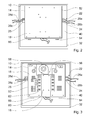
- Fig. 2 shows a portion of the hob device in a plan view of the second side 40 of the Schub99 10.
- an electronics support unit 14 of the hob device is attached on the second side 40 of the Schub device.
- the electronics carrier unit 14 has a trough shape and surrounds a receiving area for an electronics unit 16 at least partially.
- the electronics carrier unit 14 has a bottom 18 and a side wall 52.
- the base 18 On a side facing the heating element carrier unit 10, the base 18 has fastening means 20 for fastening the electronics carrier unit 14 to the heating element carrier unit 10 (cf. Fig. 5 ).
- the fastening means 20 are elastic latching hooks, which are intended to be pushed through latching openings 54 of the Schuelementziussi 10 and to secure the electronics carrier unit 14 in a rear grip on the Schuelementziappel 10.
- the cable bushings 24, 25 in the heating element carrier unit 10 are arranged such that they lie outside a surface area of the heating element carrier unit 10 provided for the electronics carrier unit 14.
- the cable gland 50 is covered by this after assembly of the electronics carrier unit 14.
- the electronics carrier unit 14 is provided for holding the electronic unit 16 and a cooling unit 56.
- Fig. 3 shows a portion of the cooktop device with the electronics carrier unit 14 and the electronics unit 16 mounted on the electronics carrier unit 14 and the cooling unit 56 mounted on the electronics carrier unit 14. Both are fastened to the electronics carrier unit 14 by means of a screw connection.
- the heating element carrier unit 10 and the electronics unit 16 are arranged on different sides of the electronics carrier unit 14.
- the electronics unit 16 includes power electronics components 62 that generate high frequency alternating currents for the heating elements 12a-d during operation of the induction hob. For cooling, the power electronics components 62 are in direct contact with an aluminum heat sink 60 of the cooling unit 56.
- the cooling unit 56 includes a cooling fan 58, which draws cooling air perpendicular to the electronics carrier unit 14 and ejects parallel to the electronics carrier unit 14 through channels of the aluminum heat sink 60. Since the cable lead-throughs 24, 25 lie outside the surface area of the heating element carrier unit 10 intended for the electronics carrier unit 14, a simple contacting of the power supply lines 26a-d to the electronic unit 16 is possible.
- Fig. 4 shows the fully assembled hob device in a perspective view from below.
- the cooktop apparatus has a cover unit 28 made of aluminum, which is intended to cover the electronics unit 16.
- the cover unit 28 is embodied at least substantially in the form of a rectangular tub with side walls 66, 67, 68, 70 that are perpendicular to a bottom wall 64.
- the bottom wall 64 has, above the cooling fan 58, air inlet openings 72, through which the cooling fan 58 sucks in cooling air in at least one operating state.
- the side wall 66 of the cover unit 28 has air outlet openings 74 through which the heated cooling air is expelled from the aluminum heat sink 60 in at least one operating state.
- the cover unit 28 comprises integrally formed and protruding tabs 76, 78 which, in an assembled state, are perpendicular to the heating element carrier unit 10.
- the cover unit 28 surrounds the electronics carrier unit 14 with the side walls 66, 67, 68, 70.
- the cover unit 28 surrounds the heating element carrier unit 10 on two opposite side edges of the heating element carrier unit 10 with the integrally formed tabs 76, 78.
- the carrier unit 30 has an overlap region 34 with the Tabs 76, 78 of the cover unit 28 (see. Fig. 5 ). In the overlapping area 34, the carrier unit 30 and the cover unit 28 touch directly and their surfaces run parallel to each other.
- the carrier unit 30 and the cover unit 28 are screwed together in the overlapping area 34.
- the carrier unit 30 has threaded holes and the tabs 76, 78 of the cover unit 28 via corresponding recesses (see. Fig. 5 ).
- the heating element carrier unit 10 and the cover unit 28 have corresponding plug-in elements 36, 37, via which the heating element carrier unit 10 and the cover unit 28 are connected to one another.
- the cover unit 28 has on the side wall 66 with the air outlet openings 74 on one edge of the side wall 66 integrally formed on tabs 80, 82, which fit into plug-in recesses 84, 86 of the Schuelementzihim 10.
- the heating element carrier unit 10 and the cover unit 28 are fixed relative to a relative movement parallel to the Bankelementlinitician 10 by the plug-in elements 36, 37.
- a fixation relative to a relative movement perpendicular to the Edelelementzitician 10 takes place by the screwing of the cover unit 28 with the carrier unit 30.
- the heating element carrier unit 10 is fixed between the carrier unit 30 and the cover unit 28 (cf. Fig. 5 ).
- the carrier unit 30 is glued to the hob plate 32.
- the heating elements 12a-d and the control electronics carrier unit 44 are fastened on the first side 38 of the heating element carrier unit 10.
- the operating electronics unit 46 is mounted on the control electronics carrier unit 44.
- the power supply lines 26a-d of the heating elements 12a-d are led through the cable feedthroughs 24, 25 to the second side 40 of the heating element carrier unit 10. Further, the power supply lines and signal lines of the operating electronics unit 46 are guided through the grommet 50 to the second side 40 of the Schuelementriadappel 10.
- the carrier unit 30 is placed together with the glued cooking field plate 32 on the first side 38 of the Schuelementlinitician 10. Afterwards the complete arrangement is turned over.
- the heater support unit 10 may be turned over and placed on the support unit 30 adhered to the cooktop panel 32.
- the electronics carrier unit 14 is attached to the second side 40 of the Schuelementmikaku 10. Thereafter, the electronics unit 16 and the cooling unit 56 are mounted on the electronics carrier unit 14.
- the power supply lines 26a-d of the heating elements 12a-d and the power supply lines and the signal lines of the operating electronics unit 46 are connected to the electronic unit 16.
- the cover unit 28 is slipped over the electronics carrier unit 14, the plug-in tabs 80, 82 being inserted on the side wall 66 of the cover unit 28 into the plug-in recesses 84, 86 of the heating element carrier unit 10.
- the cover unit 28 bolted to the tabs 76, 78 of the side walls 68, 70 with the support unit 30.
- the operating electronics unit 46 can also be preassembled on the control electronics carrier unit 44.
- the control electronics carrier unit 44 is fastened together with the preassembled operating electronics unit 46 on the first side 38 of the heating element carrier unit 10.
- the electronics unit 16 and the cooling unit 56 can also be preassembled on the electronics carrier unit 14.
- the electronics carrier unit 14 is mounted on the second side 40 of the heater support unit 10 together with the preassembled electronics unit 16 and the preassembled cooling unit 56.
- FIG. 6 shows the same cut as in FIG. 5 with the difference that the tabs 76, 78 of the cover unit 28 are not bent by not forming an overlap region 34 until the support unit 30 is reached. That is, the cover unit 28 rests on the support unit of heating elements 10, and the support unit 30 and the cover unit 28 are screwed together with the support unit held by heating elements 10 therebetween.
- the support unit 30 has screw holes, and the tabs 76, 78 of the cover unit 28 and the support unit of heating elements 10 via corresponding recesses. This is advantageous in the last step of the assembly process of the cooktop, as when mounting all the components on the cooktop panel 32, the screwing direction will be perpendicular to it and thus more ergonomic to the operator of the assembly line.
Landscapes
- Physics & Mathematics (AREA)
- Electromagnetism (AREA)
- Baking, Grill, Roasting (AREA)
- Electric Stoves And Ranges (AREA)
- Oscillators With Electromechanical Resonators (AREA)
Applications Claiming Priority (1)
| Application Number | Priority Date | Filing Date | Title |
|---|---|---|---|
| ES201031328 | 2010-09-06 |
Publications (3)
| Publication Number | Publication Date |
|---|---|
| EP2427032A2 true EP2427032A2 (fr) | 2012-03-07 |
| EP2427032A3 EP2427032A3 (fr) | 2013-01-16 |
| EP2427032B1 EP2427032B1 (fr) | 2016-12-21 |
Family
ID=44651157
Family Applications (1)
| Application Number | Title | Priority Date | Filing Date |
|---|---|---|---|
| EP11178379.1A Active EP2427032B1 (fr) | 2010-09-06 | 2011-08-23 | Dispositif de champ de cuisson |
Country Status (2)
| Country | Link |
|---|---|
| EP (1) | EP2427032B1 (fr) |
| ES (1) | ES2614406T3 (fr) |
Cited By (17)
| Publication number | Priority date | Publication date | Assignee | Title |
|---|---|---|---|---|
| EP2595450A3 (fr) * | 2011-11-16 | 2013-06-05 | BSH Electrodomésticos España, S.A. | Dispositif de cuisson |
| EP2703725A3 (fr) * | 2012-09-03 | 2014-04-23 | BSH Bosch und Siemens Hausgeräte GmbH | Dispositif de champ de cuisson |
| ES2485565A1 (es) * | 2013-02-11 | 2014-08-13 | BSH Electrodomésticos España S.A. | Dispositivo de soporte de elemento de blindaje de campo de cocción |
| EP2816869A1 (fr) * | 2013-06-21 | 2014-12-24 | BSH Bosch und Siemens Hausgeräte GmbH | Dispositif de plaque de cuisson |
| ES2537503A1 (es) * | 2013-12-05 | 2015-06-08 | Bsh Electrodomésticos España, S.A. | Dispositivo de campo de cocción |
| ES2537928A1 (es) * | 2013-12-05 | 2015-06-15 | Bsh Electrodomésticos España, S.A. | Dispositivo de campo de cocción |
| EP2981155A4 (fr) * | 2013-03-28 | 2016-04-13 | Panasonic Ip Man Co Ltd | Dispositif de cuisson par chauffage par induction |
| EP2475220B1 (fr) * | 2011-01-10 | 2016-04-13 | BSH Hausgeräte GmbH | Dispositif de champ de cuisson |
| EP3030042A1 (fr) * | 2014-12-03 | 2016-06-08 | Electrolux Appliances Aktiebolag | Plaque de cuisson à induction |
| EP3048860A4 (fr) * | 2013-09-19 | 2016-07-27 | Panasonic Ip Man Co Ltd | Cuisinière à induction |
| JPWO2016139942A1 (ja) * | 2015-03-05 | 2017-12-14 | パナソニックIpマネジメント株式会社 | 誘導加熱調理器 |
| EP2629586B1 (fr) * | 2012-02-20 | 2020-04-08 | Electrolux Home Products Corporation N.V. | Plaque de cuisson à induction |
| EP3691412A1 (fr) * | 2019-01-31 | 2020-08-05 | Miele & Cie. KG | Module de plaque de cuisson |
| EP3737211A1 (fr) * | 2019-05-06 | 2020-11-11 | E.G.O. Elektro-Gerätebau GmbH | Plaque de cuisson dotée d'une tôle portante plate pour dispositifs de chauffage et procédé de fabrication d'une telle tôle portante |
| EP3382284B1 (fr) * | 2017-03-30 | 2022-05-11 | BSH Hausgeräte GmbH | Dispositif formant appareil électroménager et procédé de fabrication d'un dispositif formant appareil électroménager |
| DE102013107089B4 (de) | 2013-07-05 | 2023-02-09 | Miele & Cie. Kg | Induktionskochfeld |
| DE102022128987A1 (de) | 2022-11-02 | 2024-05-02 | Miele & Cie. Kg | Induktionskochfeld |
Families Citing this family (5)
| Publication number | Priority date | Publication date | Assignee | Title |
|---|---|---|---|---|
| ITTO20120896A1 (it) | 2012-10-15 | 2014-04-16 | Indesit Co Spa | Piano cottura a induzione |
| US10605464B2 (en) | 2012-10-15 | 2020-03-31 | Whirlpool Corporation | Induction cooktop |
| EP3432682A1 (fr) | 2017-07-18 | 2019-01-23 | Whirlpool Corporation | Procédé de fonctionnement d'une plaque de cuisson par induction et plaque de cuisson faisant appel à un tel procédé |
| US10993292B2 (en) | 2017-10-23 | 2021-04-27 | Whirlpool Corporation | System and method for tuning an induction circuit |
| US11140751B2 (en) | 2018-04-23 | 2021-10-05 | Whirlpool Corporation | System and method for controlling quasi-resonant induction heating devices |
Citations (1)
| Publication number | Priority date | Publication date | Assignee | Title |
|---|---|---|---|---|
| DE10163839B4 (de) | 2001-12-22 | 2005-01-05 | AEG Hausgeräte GmbH | Kochmulde, insbesondere Induktionskochmulde |
Family Cites Families (4)
| Publication number | Priority date | Publication date | Assignee | Title |
|---|---|---|---|---|
| EP1122983B2 (fr) * | 2000-02-04 | 2017-12-27 | Electrolux Rothenburg GmbH Factory and Development | Appareil ménager de cuisson à induction |
| US6410892B1 (en) * | 2001-06-19 | 2002-06-25 | Bsh Home Appliances Corporation | Cooktop having a flat glass ceramic cooking surface |
| DE102005005527A1 (de) * | 2005-01-31 | 2006-08-03 | E.G.O. Elektro-Gerätebau GmbH | Induktionsheizeinrichtung und Kochfeldmulde mit einer solchen Induktionsheizeinrichtung |
| US8884197B2 (en) * | 2007-02-03 | 2014-11-11 | Western Industries, Inc. | Induction cook top with heat management system |
-
2011
- 2011-08-23 EP EP11178379.1A patent/EP2427032B1/fr active Active
- 2011-08-23 ES ES11178379.1T patent/ES2614406T3/es active Active
Patent Citations (1)
| Publication number | Priority date | Publication date | Assignee | Title |
|---|---|---|---|---|
| DE10163839B4 (de) | 2001-12-22 | 2005-01-05 | AEG Hausgeräte GmbH | Kochmulde, insbesondere Induktionskochmulde |
Cited By (26)
| Publication number | Priority date | Publication date | Assignee | Title |
|---|---|---|---|---|
| EP2475220B1 (fr) * | 2011-01-10 | 2016-04-13 | BSH Hausgeräte GmbH | Dispositif de champ de cuisson |
| EP2595450A3 (fr) * | 2011-11-16 | 2013-06-05 | BSH Electrodomésticos España, S.A. | Dispositif de cuisson |
| EP2629586B1 (fr) * | 2012-02-20 | 2020-04-08 | Electrolux Home Products Corporation N.V. | Plaque de cuisson à induction |
| EP2703725A3 (fr) * | 2012-09-03 | 2014-04-23 | BSH Bosch und Siemens Hausgeräte GmbH | Dispositif de champ de cuisson |
| ES2485565A1 (es) * | 2013-02-11 | 2014-08-13 | BSH Electrodomésticos España S.A. | Dispositivo de soporte de elemento de blindaje de campo de cocción |
| EP2765827B1 (fr) * | 2013-02-11 | 2018-01-03 | BSH Hausgeräte GmbH | Dispositif de plaque de cuisson |
| EP2981155A4 (fr) * | 2013-03-28 | 2016-04-13 | Panasonic Ip Man Co Ltd | Dispositif de cuisson par chauffage par induction |
| US9730278B2 (en) | 2013-03-28 | 2017-08-08 | Panasonic Intellectual Property Management Co., Ltd. | Induction heating cooking device |
| EP2816869A1 (fr) * | 2013-06-21 | 2014-12-24 | BSH Bosch und Siemens Hausgeräte GmbH | Dispositif de plaque de cuisson |
| DE102013107089B4 (de) | 2013-07-05 | 2023-02-09 | Miele & Cie. Kg | Induktionskochfeld |
| EP3048860A4 (fr) * | 2013-09-19 | 2016-07-27 | Panasonic Ip Man Co Ltd | Cuisinière à induction |
| ES2537928A1 (es) * | 2013-12-05 | 2015-06-15 | Bsh Electrodomésticos España, S.A. | Dispositivo de campo de cocción |
| ES2537503A1 (es) * | 2013-12-05 | 2015-06-08 | Bsh Electrodomésticos España, S.A. | Dispositivo de campo de cocción |
| EP2881671A1 (fr) * | 2013-12-05 | 2015-06-10 | BSH Hausgeräte GmbH | Dispositif de plaque de cuisson |
| CN107079538B (zh) * | 2014-12-03 | 2020-12-18 | 伊莱克斯家用电器股份公司 | 感应灶具 |
| US20170238375A1 (en) * | 2014-12-03 | 2017-08-17 | Electrolux Appliances Aktiebolag | Induction hob |
| CN107079538A (zh) * | 2014-12-03 | 2017-08-18 | 伊莱克斯家用电器股份公司 | 感应灶具 |
| WO2016087297A1 (fr) * | 2014-12-03 | 2016-06-09 | Electrolux Appliances Aktiebolag | Plaque de cuisson à induction |
| EP3030042A1 (fr) * | 2014-12-03 | 2016-06-08 | Electrolux Appliances Aktiebolag | Plaque de cuisson à induction |
| US10555381B2 (en) | 2014-12-03 | 2020-02-04 | Electrolux Appliances Aktiebolag | Induction hob |
| JPWO2016139942A1 (ja) * | 2015-03-05 | 2017-12-14 | パナソニックIpマネジメント株式会社 | 誘導加熱調理器 |
| EP3267766A4 (fr) * | 2015-03-05 | 2018-03-14 | Panasonic Intellectual Property Management Co., Ltd. | Cuisinière à chauffage par induction |
| EP3382284B1 (fr) * | 2017-03-30 | 2022-05-11 | BSH Hausgeräte GmbH | Dispositif formant appareil électroménager et procédé de fabrication d'un dispositif formant appareil électroménager |
| EP3691412A1 (fr) * | 2019-01-31 | 2020-08-05 | Miele & Cie. KG | Module de plaque de cuisson |
| EP3737211A1 (fr) * | 2019-05-06 | 2020-11-11 | E.G.O. Elektro-Gerätebau GmbH | Plaque de cuisson dotée d'une tôle portante plate pour dispositifs de chauffage et procédé de fabrication d'une telle tôle portante |
| DE102022128987A1 (de) | 2022-11-02 | 2024-05-02 | Miele & Cie. Kg | Induktionskochfeld |
Also Published As
| Publication number | Publication date |
|---|---|
| EP2427032B1 (fr) | 2016-12-21 |
| EP2427032A3 (fr) | 2013-01-16 |
| ES2614406T3 (es) | 2017-05-31 |
Similar Documents
| Publication | Publication Date | Title |
|---|---|---|
| EP2427032B1 (fr) | Dispositif de champ de cuisson | |
| EP1844630B1 (fr) | Dispositif de chauffage par induction et plaque de cuisson dotee d'un dispositif de chauffage par induction de ce type | |
| EP2703724B1 (fr) | Dispositif de plaque de cuisson et procédé de montage d'un dispositif de plaque de cuisson | |
| DE19700065C2 (de) | Filterlüfter oder Austrittsfilter | |
| EP2659195B1 (fr) | Plaque de cuisson | |
| EP2595450A2 (fr) | Dispositif de cuisson | |
| DE202015009802U1 (de) | Vorrichtung zum Laden eines elektrisch betreibbaren Fahrzeugs | |
| DE102013218714A1 (de) | Kochfeldvorrichtung | |
| EP2475220A1 (fr) | Dispositif de champ de cuisson | |
| DE102013208984B4 (de) | Steuergerät | |
| DE102014206536A1 (de) | Elektrische Maschine mit Abschirmblech | |
| EP1010582A2 (fr) | Dispositif électronique | |
| DE102013107089B4 (de) | Induktionskochfeld | |
| DE102012219264A1 (de) | Hausgerätevorrichtung | |
| DE102015222874B4 (de) | System aus Gehäuse und Leiterplatte zum mechanischen Fixieren des Gehäuses | |
| EP2765827B1 (fr) | Dispositif de plaque de cuisson | |
| DE102013207787A1 (de) | Kochfeldvorrichtung | |
| EP2703725B1 (fr) | Dispositif de champ de cuisson | |
| EP2036409A1 (fr) | Élément de blindage pour modules électroniques | |
| WO2016185301A1 (fr) | Dispositif table de cuisson et procédé mettant en oeuvre un dispositif table de cuisson | |
| EP2703726B1 (fr) | Dispositif de champ de cuisson | |
| DE102013106849A1 (de) | Gargerät | |
| DE102012101829A1 (de) | Induktionskochfeld | |
| EP3691412B1 (fr) | Module de plaque de cuisson | |
| DE202004008514U1 (de) | Induktionskochfeld |
Legal Events
| Date | Code | Title | Description |
|---|---|---|---|
| AK | Designated contracting states |
Kind code of ref document: A2 Designated state(s): AL AT BE BG CH CY CZ DE DK EE ES FI FR GB GR HR HU IE IS IT LI LT LU LV MC MK MT NL NO PL PT RO RS SE SI SK SM TR |
|
| AX | Request for extension of the european patent |
Extension state: BA ME |
|
| PUAI | Public reference made under article 153(3) epc to a published international application that has entered the european phase |
Free format text: ORIGINAL CODE: 0009012 |
|
| PUAL | Search report despatched |
Free format text: ORIGINAL CODE: 0009013 |
|
| AK | Designated contracting states |
Kind code of ref document: A3 Designated state(s): AL AT BE BG CH CY CZ DE DK EE ES FI FR GB GR HR HU IE IS IT LI LT LU LV MC MK MT NL NO PL PT RO RS SE SI SK SM TR |
|
| AX | Request for extension of the european patent |
Extension state: BA ME |
|
| RIC1 | Information provided on ipc code assigned before grant |
Ipc: H05B 6/12 20060101AFI20121207BHEP |
|
| 17P | Request for examination filed |
Effective date: 20130716 |
|
| RBV | Designated contracting states (corrected) |
Designated state(s): AL AT BE BG CH CY CZ DE DK EE ES FI FR GB GR HR HU IE IS IT LI LT LU LV MC MK MT NL NO PL PT RO RS SE SI SK SM TR |
|
| 17Q | First examination report despatched |
Effective date: 20130923 |
|
| RAP1 | Party data changed (applicant data changed or rights of an application transferred) |
Owner name: BSH HAUSGERAETE GMBH |
|
| GRAP | Despatch of communication of intention to grant a patent |
Free format text: ORIGINAL CODE: EPIDOSNIGR1 |
|
| INTG | Intention to grant announced |
Effective date: 20160722 |
|
| GRAS | Grant fee paid |
Free format text: ORIGINAL CODE: EPIDOSNIGR3 |
|
| GRAA | (expected) grant |
Free format text: ORIGINAL CODE: 0009210 |
|
| AK | Designated contracting states |
Kind code of ref document: B1 Designated state(s): AL AT BE BG CH CY CZ DE DK EE ES FI FR GB GR HR HU IE IS IT LI LT LU LV MC MK MT NL NO PL PT RO RS SE SI SK SM TR |
|
| REG | Reference to a national code |
Ref country code: GB Ref legal event code: FG4D Free format text: NOT ENGLISH |
|
| REG | Reference to a national code |
Ref country code: CH Ref legal event code: EP |
|
| REG | Reference to a national code |
Ref country code: IE Ref legal event code: FG4D Free format text: LANGUAGE OF EP DOCUMENT: GERMAN |
|
| REG | Reference to a national code |
Ref country code: AT Ref legal event code: REF Ref document number: 856474 Country of ref document: AT Kind code of ref document: T Effective date: 20170115 |
|
| REG | Reference to a national code |
Ref country code: DE Ref legal event code: R096 Ref document number: 502011011372 Country of ref document: DE |
|
| PG25 | Lapsed in a contracting state [announced via postgrant information from national office to epo] |
Ref country code: LV Free format text: LAPSE BECAUSE OF FAILURE TO SUBMIT A TRANSLATION OF THE DESCRIPTION OR TO PAY THE FEE WITHIN THE PRESCRIBED TIME-LIMIT Effective date: 20161221 |
|
| REG | Reference to a national code |
Ref country code: LT Ref legal event code: MG4D |
|
| REG | Reference to a national code |
Ref country code: NL Ref legal event code: MP Effective date: 20161221 |
|
| PG25 | Lapsed in a contracting state [announced via postgrant information from national office to epo] |
Ref country code: GR Free format text: LAPSE BECAUSE OF FAILURE TO SUBMIT A TRANSLATION OF THE DESCRIPTION OR TO PAY THE FEE WITHIN THE PRESCRIBED TIME-LIMIT Effective date: 20170322 Ref country code: SE Free format text: LAPSE BECAUSE OF FAILURE TO SUBMIT A TRANSLATION OF THE DESCRIPTION OR TO PAY THE FEE WITHIN THE PRESCRIBED TIME-LIMIT Effective date: 20161221 Ref country code: LT Free format text: LAPSE BECAUSE OF FAILURE TO SUBMIT A TRANSLATION OF THE DESCRIPTION OR TO PAY THE FEE WITHIN THE PRESCRIBED TIME-LIMIT Effective date: 20161221 Ref country code: NO Free format text: LAPSE BECAUSE OF FAILURE TO SUBMIT A TRANSLATION OF THE DESCRIPTION OR TO PAY THE FEE WITHIN THE PRESCRIBED TIME-LIMIT Effective date: 20170321 |
|
| PG25 | Lapsed in a contracting state [announced via postgrant information from national office to epo] |
Ref country code: RS Free format text: LAPSE BECAUSE OF FAILURE TO SUBMIT A TRANSLATION OF THE DESCRIPTION OR TO PAY THE FEE WITHIN THE PRESCRIBED TIME-LIMIT Effective date: 20161221 Ref country code: FI Free format text: LAPSE BECAUSE OF FAILURE TO SUBMIT A TRANSLATION OF THE DESCRIPTION OR TO PAY THE FEE WITHIN THE PRESCRIBED TIME-LIMIT Effective date: 20161221 Ref country code: HR Free format text: LAPSE BECAUSE OF FAILURE TO SUBMIT A TRANSLATION OF THE DESCRIPTION OR TO PAY THE FEE WITHIN THE PRESCRIBED TIME-LIMIT Effective date: 20161221 |
|
| REG | Reference to a national code |
Ref country code: ES Ref legal event code: FG2A Ref document number: 2614406 Country of ref document: ES Kind code of ref document: T3 Effective date: 20170531 |
|
| PG25 | Lapsed in a contracting state [announced via postgrant information from national office to epo] |
Ref country code: NL Free format text: LAPSE BECAUSE OF FAILURE TO SUBMIT A TRANSLATION OF THE DESCRIPTION OR TO PAY THE FEE WITHIN THE PRESCRIBED TIME-LIMIT Effective date: 20161221 |
|
| PG25 | Lapsed in a contracting state [announced via postgrant information from national office to epo] |
Ref country code: SK Free format text: LAPSE BECAUSE OF FAILURE TO SUBMIT A TRANSLATION OF THE DESCRIPTION OR TO PAY THE FEE WITHIN THE PRESCRIBED TIME-LIMIT Effective date: 20161221 Ref country code: EE Free format text: LAPSE BECAUSE OF FAILURE TO SUBMIT A TRANSLATION OF THE DESCRIPTION OR TO PAY THE FEE WITHIN THE PRESCRIBED TIME-LIMIT Effective date: 20161221 Ref country code: RO Free format text: LAPSE BECAUSE OF FAILURE TO SUBMIT A TRANSLATION OF THE DESCRIPTION OR TO PAY THE FEE WITHIN THE PRESCRIBED TIME-LIMIT Effective date: 20161221 Ref country code: CZ Free format text: LAPSE BECAUSE OF FAILURE TO SUBMIT A TRANSLATION OF THE DESCRIPTION OR TO PAY THE FEE WITHIN THE PRESCRIBED TIME-LIMIT Effective date: 20161221 Ref country code: IS Free format text: LAPSE BECAUSE OF FAILURE TO SUBMIT A TRANSLATION OF THE DESCRIPTION OR TO PAY THE FEE WITHIN THE PRESCRIBED TIME-LIMIT Effective date: 20170421 |
|
| REG | Reference to a national code |
Ref country code: FR Ref legal event code: PLFP Year of fee payment: 7 |
|
| PG25 | Lapsed in a contracting state [announced via postgrant information from national office to epo] |
Ref country code: PL Free format text: LAPSE BECAUSE OF FAILURE TO SUBMIT A TRANSLATION OF THE DESCRIPTION OR TO PAY THE FEE WITHIN THE PRESCRIBED TIME-LIMIT Effective date: 20161221 Ref country code: IT Free format text: LAPSE BECAUSE OF FAILURE TO SUBMIT A TRANSLATION OF THE DESCRIPTION OR TO PAY THE FEE WITHIN THE PRESCRIBED TIME-LIMIT Effective date: 20161221 Ref country code: PT Free format text: LAPSE BECAUSE OF FAILURE TO SUBMIT A TRANSLATION OF THE DESCRIPTION OR TO PAY THE FEE WITHIN THE PRESCRIBED TIME-LIMIT Effective date: 20170421 Ref country code: BG Free format text: LAPSE BECAUSE OF FAILURE TO SUBMIT A TRANSLATION OF THE DESCRIPTION OR TO PAY THE FEE WITHIN THE PRESCRIBED TIME-LIMIT Effective date: 20170321 Ref country code: SM Free format text: LAPSE BECAUSE OF FAILURE TO SUBMIT A TRANSLATION OF THE DESCRIPTION OR TO PAY THE FEE WITHIN THE PRESCRIBED TIME-LIMIT Effective date: 20161221 |
|
| REG | Reference to a national code |
Ref country code: DE Ref legal event code: R097 Ref document number: 502011011372 Country of ref document: DE |
|
| PLBE | No opposition filed within time limit |
Free format text: ORIGINAL CODE: 0009261 |
|
| STAA | Information on the status of an ep patent application or granted ep patent |
Free format text: STATUS: NO OPPOSITION FILED WITHIN TIME LIMIT |
|
| 26N | No opposition filed |
Effective date: 20170922 |
|
| PG25 | Lapsed in a contracting state [announced via postgrant information from national office to epo] |
Ref country code: DK Free format text: LAPSE BECAUSE OF FAILURE TO SUBMIT A TRANSLATION OF THE DESCRIPTION OR TO PAY THE FEE WITHIN THE PRESCRIBED TIME-LIMIT Effective date: 20161221 |
|
| PG25 | Lapsed in a contracting state [announced via postgrant information from national office to epo] |
Ref country code: SI Free format text: LAPSE BECAUSE OF FAILURE TO SUBMIT A TRANSLATION OF THE DESCRIPTION OR TO PAY THE FEE WITHIN THE PRESCRIBED TIME-LIMIT Effective date: 20161221 |
|
| REG | Reference to a national code |
Ref country code: CH Ref legal event code: PL |
|
| PG25 | Lapsed in a contracting state [announced via postgrant information from national office to epo] |
Ref country code: MC Free format text: LAPSE BECAUSE OF FAILURE TO SUBMIT A TRANSLATION OF THE DESCRIPTION OR TO PAY THE FEE WITHIN THE PRESCRIBED TIME-LIMIT Effective date: 20161221 |
|
| GBPC | Gb: european patent ceased through non-payment of renewal fee |
Effective date: 20170823 |
|
| PG25 | Lapsed in a contracting state [announced via postgrant information from national office to epo] |
Ref country code: LI Free format text: LAPSE BECAUSE OF NON-PAYMENT OF DUE FEES Effective date: 20170831 Ref country code: CH Free format text: LAPSE BECAUSE OF NON-PAYMENT OF DUE FEES Effective date: 20170831 |
|
| REG | Reference to a national code |
Ref country code: IE Ref legal event code: MM4A |
|
| REG | Reference to a national code |
Ref country code: BE Ref legal event code: MM Effective date: 20170831 |
|
| PG25 | Lapsed in a contracting state [announced via postgrant information from national office to epo] |
Ref country code: LU Free format text: LAPSE BECAUSE OF NON-PAYMENT OF DUE FEES Effective date: 20170823 |
|
| PG25 | Lapsed in a contracting state [announced via postgrant information from national office to epo] |
Ref country code: GB Free format text: LAPSE BECAUSE OF NON-PAYMENT OF DUE FEES Effective date: 20170823 Ref country code: IE Free format text: LAPSE BECAUSE OF NON-PAYMENT OF DUE FEES Effective date: 20170823 |
|
| REG | Reference to a national code |
Ref country code: FR Ref legal event code: PLFP Year of fee payment: 8 |
|
| PG25 | Lapsed in a contracting state [announced via postgrant information from national office to epo] |
Ref country code: BE Free format text: LAPSE BECAUSE OF NON-PAYMENT OF DUE FEES Effective date: 20170831 |
|
| PG25 | Lapsed in a contracting state [announced via postgrant information from national office to epo] |
Ref country code: MT Free format text: LAPSE BECAUSE OF FAILURE TO SUBMIT A TRANSLATION OF THE DESCRIPTION OR TO PAY THE FEE WITHIN THE PRESCRIBED TIME-LIMIT Effective date: 20161221 |
|
| REG | Reference to a national code |
Ref country code: AT Ref legal event code: MM01 Ref document number: 856474 Country of ref document: AT Kind code of ref document: T Effective date: 20170823 |
|
| PG25 | Lapsed in a contracting state [announced via postgrant information from national office to epo] |
Ref country code: AT Free format text: LAPSE BECAUSE OF NON-PAYMENT OF DUE FEES Effective date: 20170823 |
|
| PG25 | Lapsed in a contracting state [announced via postgrant information from national office to epo] |
Ref country code: HU Free format text: LAPSE BECAUSE OF FAILURE TO SUBMIT A TRANSLATION OF THE DESCRIPTION OR TO PAY THE FEE WITHIN THE PRESCRIBED TIME-LIMIT; INVALID AB INITIO Effective date: 20110823 |
|
| PG25 | Lapsed in a contracting state [announced via postgrant information from national office to epo] |
Ref country code: CY Free format text: LAPSE BECAUSE OF NON-PAYMENT OF DUE FEES Effective date: 20161221 |
|
| PG25 | Lapsed in a contracting state [announced via postgrant information from national office to epo] |
Ref country code: MK Free format text: LAPSE BECAUSE OF FAILURE TO SUBMIT A TRANSLATION OF THE DESCRIPTION OR TO PAY THE FEE WITHIN THE PRESCRIBED TIME-LIMIT Effective date: 20161221 |
|
| PG25 | Lapsed in a contracting state [announced via postgrant information from national office to epo] |
Ref country code: TR Free format text: LAPSE BECAUSE OF FAILURE TO SUBMIT A TRANSLATION OF THE DESCRIPTION OR TO PAY THE FEE WITHIN THE PRESCRIBED TIME-LIMIT Effective date: 20161221 |
|
| PG25 | Lapsed in a contracting state [announced via postgrant information from national office to epo] |
Ref country code: AL Free format text: LAPSE BECAUSE OF FAILURE TO SUBMIT A TRANSLATION OF THE DESCRIPTION OR TO PAY THE FEE WITHIN THE PRESCRIBED TIME-LIMIT Effective date: 20161221 |
|
| REG | Reference to a national code |
Ref country code: DE Ref legal event code: R084 Ref document number: 502011011372 Country of ref document: DE |
|
| P01 | Opt-out of the competence of the unified patent court (upc) registered |
Effective date: 20230504 |
|
| PGFP | Annual fee paid to national office [announced via postgrant information from national office to epo] |
Ref country code: ES Payment date: 20230918 Year of fee payment: 13 |
|
| PGFP | Annual fee paid to national office [announced via postgrant information from national office to epo] |
Ref country code: FR Payment date: 20230821 Year of fee payment: 13 Ref country code: DE Payment date: 20230831 Year of fee payment: 13 |