EP3737211A1 - Plaque de cuisson dotée d'une tôle portante plate pour dispositifs de chauffage et procédé de fabrication d'une telle tôle portante - Google Patents
Plaque de cuisson dotée d'une tôle portante plate pour dispositifs de chauffage et procédé de fabrication d'une telle tôle portante Download PDFInfo
- Publication number
- EP3737211A1 EP3737211A1 EP20169525.1A EP20169525A EP3737211A1 EP 3737211 A1 EP3737211 A1 EP 3737211A1 EP 20169525 A EP20169525 A EP 20169525A EP 3737211 A1 EP3737211 A1 EP 3737211A1
- Authority
- EP
- European Patent Office
- Prior art keywords
- support plate
- reinforcement
- embossing
- impression
- hob according
- Prior art date
- Legal status (The legal status is an assumption and is not a legal conclusion. Google has not performed a legal analysis and makes no representation as to the accuracy of the status listed.)
- Granted
Links
- 238000010438 heat treatment Methods 0.000 title claims abstract description 24
- 238000004519 manufacturing process Methods 0.000 title claims description 9
- 238000000034 method Methods 0.000 title description 6
- 230000002787 reinforcement Effects 0.000 claims abstract description 118
- 229910052751 metal Inorganic materials 0.000 claims abstract description 6
- 239000002184 metal Substances 0.000 claims abstract description 6
- 238000004049 embossing Methods 0.000 claims description 57
- 230000003014 reinforcing effect Effects 0.000 claims description 26
- 238000005452 bending Methods 0.000 abstract description 4
- 230000006698 induction Effects 0.000 description 11
- 239000000463 material Substances 0.000 description 5
- 238000013461 design Methods 0.000 description 4
- 230000000694 effects Effects 0.000 description 3
- 229910052782 aluminium Inorganic materials 0.000 description 2
- XAGFODPZIPBFFR-UHFFFAOYSA-N aluminium Chemical compound [Al] XAGFODPZIPBFFR-UHFFFAOYSA-N 0.000 description 2
- 238000007373 indentation Methods 0.000 description 2
- 239000007769 metal material Substances 0.000 description 2
- 238000003825 pressing Methods 0.000 description 2
- 238000007665 sagging Methods 0.000 description 2
- 239000000969 carrier Substances 0.000 description 1
- 238000005260 corrosion Methods 0.000 description 1
- 230000007797 corrosion Effects 0.000 description 1
- 230000006735 deficit Effects 0.000 description 1
- 238000011161 development Methods 0.000 description 1
- 230000018109 developmental process Effects 0.000 description 1
- 239000011888 foil Substances 0.000 description 1
- 230000017525 heat dissipation Effects 0.000 description 1
- 238000009434 installation Methods 0.000 description 1
- 238000012986 modification Methods 0.000 description 1
- 230000004048 modification Effects 0.000 description 1
- 230000003287 optical effect Effects 0.000 description 1
- 238000012545 processing Methods 0.000 description 1
- 238000004080 punching Methods 0.000 description 1
- 238000005096 rolling process Methods 0.000 description 1
- 239000004065 semiconductor Substances 0.000 description 1
- 238000009423 ventilation Methods 0.000 description 1
- 238000003466 welding Methods 0.000 description 1
Images


Classifications
-
- H—ELECTRICITY
- H05—ELECTRIC TECHNIQUES NOT OTHERWISE PROVIDED FOR
- H05B—ELECTRIC HEATING; ELECTRIC LIGHT SOURCES NOT OTHERWISE PROVIDED FOR; CIRCUIT ARRANGEMENTS FOR ELECTRIC LIGHT SOURCES, IN GENERAL
- H05B3/00—Ohmic-resistance heating
- H05B3/68—Heating arrangements specially adapted for cooking plates or analogous hot-plates
- H05B3/72—Plates of sheet metal
-
- H—ELECTRICITY
- H05—ELECTRIC TECHNIQUES NOT OTHERWISE PROVIDED FOR
- H05B—ELECTRIC HEATING; ELECTRIC LIGHT SOURCES NOT OTHERWISE PROVIDED FOR; CIRCUIT ARRANGEMENTS FOR ELECTRIC LIGHT SOURCES, IN GENERAL
- H05B6/00—Heating by electric, magnetic or electromagnetic fields
- H05B6/02—Induction heating
- H05B6/10—Induction heating apparatus, other than furnaces, for specific applications
- H05B6/12—Cooking devices
- H05B6/1209—Cooking devices induction cooking plates or the like and devices to be used in combination with them
-
- F—MECHANICAL ENGINEERING; LIGHTING; HEATING; WEAPONS; BLASTING
- F24—HEATING; RANGES; VENTILATING
- F24C—DOMESTIC STOVES OR RANGES ; DETAILS OF DOMESTIC STOVES OR RANGES, OF GENERAL APPLICATION
- F24C15/00—Details
- F24C15/10—Tops, e.g. hot plates; Rings
-
- F—MECHANICAL ENGINEERING; LIGHTING; HEATING; WEAPONS; BLASTING
- F24—HEATING; RANGES; VENTILATING
- F24C—DOMESTIC STOVES OR RANGES ; DETAILS OF DOMESTIC STOVES OR RANGES, OF GENERAL APPLICATION
- F24C7/00—Stoves or ranges heated by electric energy
- F24C7/08—Arrangement or mounting of control or safety devices
-
- H—ELECTRICITY
- H05—ELECTRIC TECHNIQUES NOT OTHERWISE PROVIDED FOR
- H05B—ELECTRIC HEATING; ELECTRIC LIGHT SOURCES NOT OTHERWISE PROVIDED FOR; CIRCUIT ARRANGEMENTS FOR ELECTRIC LIGHT SOURCES, IN GENERAL
- H05B2206/00—Aspects relating to heating by electric, magnetic, or electromagnetic fields covered by group H05B6/00
- H05B2206/02—Induction heating
- H05B2206/022—Special supports for the induction coils
Definitions
- the invention relates to a hob with a flat support plate made of metal, on which heating devices are arranged, in particular induction heating devices.
- the invention also relates to a method for producing a support plate for such a hob or such a support plate.
- the invention is based on the object of creating a hob and a method for producing a support plate of such a hob, with which problems of the prior art can be solved and in particular it is possible to support a support plate against sagging in a central area or as a whole.
- the hob has a flat support plate, in particular made of metal, on which heating devices are arranged. All the heating devices of the hob are advantageously arranged on a single support plate or the hob has only a single support plate.
- the hob particularly advantageously has a single support plate which can take up a substantial area of the hob, in particular 60% to 90% or even up to 98%, or the hob plate.
- the support plate can consist of a metal sheet, preferably with a thickness of 0.5 mm to 2 mm.
- aluminum is suitable here because of its corrosion resistance, its relatively low weight, its ease of processing and its good heat dissipation properties.
- the hob also has a control and / or power controller for the heating devices.
- the control can be a control device, in particular with an operating device including operating elements and control electronics or integrated circuits.
- the power controllers can be converters, in particular in the case of induction heating devices, and have power electronics, in particular semiconductor line switches.
- the control and / or power controller can be arranged under the support plate, advantageously in a housing. An operating device is advantageously arranged on the support plate.
- the support plate has at least one reinforcement embossing which is elongated and runs in a direction from one outside of the support plate to an opposite outside.
- the at least one reinforcement embossment therefore advantageously spans a central area of the support plate in order to reinforce it or make it more stable against being pushed through or bent. It is particularly advantageous if several reinforcing impressions are provided, which can all run parallel to one another and can be designed in a similar or identical manner.
- the embossed reinforcement protrudes from a surface of the support plate or protrudes beyond the surface of the support plate, at least in an area adjoining the embossed reinforcement, that is, an adjacent area, in particular downwards.
- Such possibilities for reinforcing or stiffening flat metal sheets are generally known to the person skilled in the art.
- the embossed reinforcement has a length which corresponds to at least 80% of the distance from one outer side of the support plate to the opposite outer side. It is advantageously even longer, in particular it extends from outside to outside.
- the reinforcement impression can have a width which corresponds to 2% to 20%, in particular 3% to 10%, of its length.
- the embossed reinforcement should therefore be relatively narrow, which, on the one hand, has as little effect as possible on the otherwise flat and flat design of the support plate for its use. On the other hand the effect of reinforcing or stiffening the support plate can thereby be further improved.
- the means for reinforcing the support plate are, so to speak, integrated into the support plate and thus in particular made in one piece and in one piece in the support plate or with the support plate. Due to the relatively great length of the reinforcement impression, in particular the running from one outside to the opposite outside, the reinforcement or stiffening also acts over a large area for the entire support plate. An additional use of separate carriers or the like. can then be saved.
- the reinforcement embossing has a cross-sectional shape, in particular as a U-shape or U-like shape, which has a base and side walls on both sides of the base from the surface of the support plate to the base.
- a reinforcement indentation can therefore be designed like an elongated flat depression or channel.
- Their side walls can run obliquely to the floor and towards each other, so that the cross-sectional shape of the reinforcement impression tapers downwards or towards its floor. This facilitates production by means of an embossing process, in particular by means of the method according to the invention with embossing.
- the reinforcement embossing can also be produced differently within the scope of the invention, for example by bending, folding or rolling.
- the cross-sectional shape can have relatively sharp edges, that is, can be angled relatively sharply, which further increases the strength.
- a radius of the bends from the side walls of the reinforcement impression to the surface of the support plate on the one hand and / or the bottom of the reinforcement impression on the other hand can be in the range between 50% and 200% to 300% of the thickness of the support plate.
- An angle between the side walls and a surface of the support plate can be between 20 ° and 75 °, in particular between 35 ° and 60 °.
- the cross-sectional shape of the reinforcement impression is symmetrical or mirror-symmetrical.
- a symmetrical surface runs at right angles to the surface of the support plate and along the longitudinal direction of the reinforcement impression, namely along the center of the reinforcement impression. On the one hand, this can be produced more easily and, on the other hand, it develops a uniform reinforcing effect.
- a bottom of the reinforcement impression is preferably flat. Additionally or alternatively, it can run parallel to a surface of the support plate, only offset therefrom by the depth of the reinforcement impression. This depth can be between 50% and 500% of the thickness of the support plate, preferably between 150% and 300%. Alternatively expressed the depth or the height of the reinforcement indentation with which it protrudes over the surface of the support plate can be between 5% and 20% of its maximum width.
- the reinforcement embossing advantageously has a constant width, and if possible also a constant depth.
- a certain reinforcing effect is achieved by a single reinforcing impression, which then advantageously runs approximately through a center point or central region of the support plate.
- the support plate has at least two reinforcing embossings, which in particular run parallel to one another and are of the same length, and advantageously also have the same or identical design. It is particularly advantageous to have four or six reinforcement impressions. This is particularly advantageous when the reinforcement impressions are to take on additional functions in addition to reinforcing or stiffening the support plate.
- At least one reinforcement embossing runs along and parallel to an outside of the support plate.
- the support plate can thus be reinforced or supported even in the area of its outer sides.
- a distance between the reinforcement embossing and the outside running parallel to it can here be less than 10 cm or 8 cm, preferably it is less than 5 cm. This is particularly advantageous when something is attached to it, as will be explained in more detail below.
- At least one further reinforcing impression then runs in a central region of the support plate or through the center. It can either be exactly in the middle between two outer sides to which it is parallel.
- a single reinforcing impression can then run in a similar or identical shape in a central region of the support plate.
- two identical reinforcement impressions can run at a distance of less than 10 cm from one another. This is particularly advantageous when the reinforcement embossing takes on additional functions, preferably when functional units run in it or when something is attached to it.
- a length of the reinforcement embossments can span as much as possible of the support plate.
- At least one reinforcement embossing preferably each, seen in its longitudinal direction at least up to a distance of a maximum of 2 cm, in particular a maximum of 1 cm, can extend to the outside of the support plate when looking at the support plate from above or below. It is particularly advantageous if a reinforcement embossment extends directly to an outside of the support plate, that is to say it is as long as possible. This also applies in the event that this outside, in particular all outside of the support plate, is angled at an angle of at least 45 °, usually about 90 °.
- This also serves to increase the reinforcement of the support plate, as well as an angular surface can be formed in order to attach something to it.
- a bend along the outside of the support plate can advantageously go in the same direction in which the embossed reinforcement also projects away from the support plate, advantageously downwards.
- recesses are provided in the side walls of the reinforcing embossing, that is, between its base and the other surface of the support plate. These recesses are preferably provided in a regular arrangement. They are preferably longer in the longitudinal direction of the reinforcement embossing than webs in between. Furthermore, the recesses are advantageously arranged along a line, in particular along a straight line, since the reinforcement impressions are also preferably straight.
- the ratio of the length of the recesses to the length of the webs in between can be between 50% and 500%, so that these recesses are more or less several times longer than the webs in between.
- the aforementioned recesses are preferably provided essentially, in particular exclusively, in the side walls and only little or not at all in the other surfaces of the support plate and / or in the bottom of the reinforcement embossing. So, if possible, they are only provided in the area of the deformation of the support plate in order to be deformed itself or to enable this deformation as easily as possible and, if possible, to have into the support plate without forces or stresses that could cause it to warp or bulge from its preferably substantially flat shape.
- the recesses mentioned are advantageously not only designed as narrow elongated slots, but also as elongated rectangles. Their length should correspond to the distance between adjacent webs, their width should be between 5% and 30% of the length, in particular 8% to 25%. Alternatively expressed, the width can be between 50% and 150% of the depth of the reinforcement impression.
- the recesses are advantageously predominantly of the same size, in particular almost all or all of the recesses are of the same size. This enables a uniform behavior when producing the reinforcement impression.
- additional openings can be provided along the reinforcement impression, which are designed in the manner of elongated slots. They preferably run at a distance between 0.5 cm and 5 cm, in particular between 0.5 cm and 2 cm, to the reinforcement embossing or to the aforementioned recesses.
- the openings are preferably designed like slits and are narrower than the aforementioned recesses. In particular, their length is four to thirty times their width. The distance between adjacent openings to one another can be between 5% and 50% of the length of such an opening.
- Such openings are advantageously provided along both sides of the reinforcement impression, but in particular between a reinforcement impression and a heating device arranged on the support plate. In this way, they can greatly reduce heat conduction across their longitudinal direction.
- the reinforcement embossing has a bottom that deviates from the planar shape.
- the bottom can have an upward curvature, that is to say in the opposite direction with which the reinforcement embossing was embossed into the support plate.
- the direction of curvature can at the same time be formed transversely to the longitudinal direction of the reinforcement impression. It can form a kind of crown in order to additionally stabilize the reinforcement impression.
- the height of the bulge can be between 1% and 10% of the width of the floor.
- a functional unit or a component of the hob can be laid or accommodated in a reinforcement embossing.
- cables, connections and / or sensors can be laid therein.
- the aforementioned relatively small depth of the reinforcement impression is sufficient for this.
- lighting means in particular light guides, can run therein. Parts running in it should not protrude upwards beyond the reinforcement embossing, but can do so if necessary, depending on the installation space available above.
- a control housing can be provided on the hob for the aforementioned control and / or the power controller.
- a control housing can be flat and large and arranged under the support plate. It can preferably be attached or screwed to the support plate from below.
- Such a control housing is advantageously screwed only to the undersides of two spaced-apart reinforcement impressions. In this way, the depth of the reinforcement impressions can be used to hold screw heads, nuts or threaded parts without these protruding upwards beyond the surface of the support plate.
- a hob preferably has two or three similar or identical control housings, each of which is attached to its own two reinforcing impressions. Thus, four or six reinforcement embossings are provided for the hob. With a width of about 55 cm to 60 cm for the hob, there can be two control housings with four reinforcement embossments, with a width of 80 cm to 90 cm it is advantageous to have three control housings with six reinforcement embossments.
- a support plate is advantageously embossed or processed in a single step. This serves to reduce deformations that may not be desirable.
- the support plate can be provided with all openings and recesses or other punched-out parts in a single step.
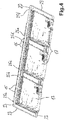
- a hob 11 according to the invention is shown in side view.
- the hob 11 has a hob plate 12 at the top, under which several induction heating coils 14 are arranged.
- the oblique view of the Fig. 3 shows that four operating devices 15 are arranged in the front area, each having optical display devices and capacitive operating elements, as is known from the prior art.
- the oblique view of the Fig. 4 shows three identical or identical control housings 17 screwed to a support plate 20. These control housings contain a control and / or power controller for the induction heating coils 14. Therefore, they also have ventilation slots in the front area and fans in the rear area, as is known per se from the prior art.
- the induction heating coils 14 and the operating devices 15 are also mounted on the support plate 20 or lie on it and are carried by it.
- the numerous smaller openings in the support plate 20 can be used for precise fixing, as is the case with the Fig. 5 can be found. Through out Fig. 5 Through the large openings 22 that can be seen, the induction heating coils 14 can easily be cabled into the control housing 17 below.
- the support plate 20 has developments 23 along its outer sides, which according to the side view of FIG Fig. 6 are bent downwards at right angles.
- the entire support plate 20 is advantageously made of aluminum sheet, particularly advantageously with a thickness of about 1.5 mm.
- Six reinforcing impressions 25a to 25f are made in a surface 21 of the support plate 20.
- they are all identical and essentially the only areas of the surface 21 of the support plate 20 which are embossed.
- Each reinforcement impression 25a to 25f has a bottom 27 and side walls 29.
- the enlargements of the Figures 7 and 8 show that the side walls 29b and 29c of the reinforcement impressions 25b and 25c are essentially formed by short webs 33b and 33c. Between these elongated recesses 31b and 31c are made in the sheet metal material of the support plate 20 or punched out of it. There where the reinforcement impressions 25 are drawn up to the outer sides of the support plate 20 and thus up to the bends 23, somewhat larger punchings 35 are provided in the Fig. 7 these are the cutouts 35b and 35c. They allow the bends 23 to be bent easily without distortion. From the Fig.
- a length of the recesses 31b and 31c is approximately three times the length of the webs 33b and 33c in the longitudinal direction of the reinforcement impressions 25b and 25c.
- warping or any other distortion in the support plate 20 can be avoided if the reinforcing impressions 25 are embossed or produced by embossing.
- the material of the support plate 20 can then flow well, as was explained at the beginning. In this way it can also be achieved that the reinforcement impressions 25 cannot be produced with too much force during the stamping.
- a U-like cross-sectional shape of the reinforcement impressions 25 is from FIG Fig. 9 easy to see.
- the depth, so to speak the difference in height between the surface 21 of the support plate 20 and the bottom 27 of the reinforcement impression 25, is slightly more than the thickness of the support plate 20 itself, for example 2 mm to 2.5 mm.
- this is sufficient for the significant mechanical reinforcement of the entire support plate 20 against bending due to the weight of the Fig. 3 recognizable induction heating coils 14 together with sensor coils placed on them. This is important and advantageous especially in the middle area of the support plate 20 between the reinforcement impressions 25c and 25d.
- An angle of the inclination of the side walls 29 to the surface 21 of the support plate 20 cannot be precisely determined because the side walls are admittedly not very high and due to of the Fig. 9 recognizable curved course, an angle is difficult to specify.
- a possible course of a straight line between two points, which are each half the thickness of the support plate 20, before the surface 21 of the support plate 20 merges into the web 33 and before the bottom 27b merges to the left into the same web 33b is shown in dashed lines. This angle is approximately 45 °, the inclination of the web 33b admittedly looking more oblique or suggesting a larger angle.
- the embossing or production of the reinforcement embossments 25 does not impair the material in the essential surface 21 of the support plate 20, nor actually in the bottom 27 of the reinforcement embossments 25. Both the deformation and a possible one negative impairment of the material takes place only in the side walls or the webs 33 of the reinforcement impressions 25. If their deformation is kept within limits by the embossing, they are still sufficiently stable.
- Three holes 38 are provided along the bottom 27 of the reinforcing impressions 25.
- the control housing 17 can be fastened to these holes from below, advantageously by screwing them tight. Screws introduced from above can then have a height or thickness of the screw heads up to the aforementioned 2 mm and still remain below the plane of the surface 21 of the support plate 20. So they do not interfere with the induction heating coils 14 or other functional units placed above it.
- cables, connections, sensors or light guides or the like can also run in the channels formed by the reinforcement embossments 25. Then they have a function similar to that of cable ducts. In addition, they could also be closed at the top by thin foils or thin lids.
- oblong openings 40b are also provided in the enlargements on the left and right next to the reinforcement impression 25b. They run exactly parallel to it and have a length which can correspond approximately to the length of the recesses 31. Their width can be about a quarter of their length.
- a web 33b is arranged approximately in the center of each opening 40b, or the openings 40b are thus constantly offset from the recesses 31b.
- the purpose of these openings 40b is to reduce heat conduction, in particular from the applied induction heating coils 14 into the reinforcement embossments 25 or their bases 27, to which the control housing 17 are attached.
- the narrow areas which are formed between each opening 40b and each web 33b can possibly reduce negative influences of the embossing on the flat configuration of the surface 21 of the support plate 20. In these narrow ones In areas, the material of the support plate 20 can, so to speak, still yield somewhat during embossing.
- a width of a reinforcement impression 25 can be approximately ten times its depth. However, this can vary noticeably.
- FIG. 10 Another cross-sectional shape for a reinforcement impression 125 is shown in simplified form. It is triangular in profile with the tip pointing downwards. The side walls 129 are approximately the same length and are at approximately the same angle to the surface 121 of the support plate 120. Thus, a right angle is formed at the bottom in the reinforcing impression 125. Such a reinforcing impression 125 is obviously more difficult to manufacture than that previously described according to FIG Figs. 1 to 9 . Due to its greater depth, however, it probably also gives the support plate 120 greater rigidity or provides greater reinforcement against sagging.
- Fig. 11 shows yet another variation of how a reinforcing embossment 225 can be made in a support plate 220.
- the cross-sectional shape here is also U-like, but about twice as deep as it is wide.
- This reinforcement embossing 225 rather forms a type of reinforcing rib protruding downward from the surface 221 of the support plate 220 with two relatively long side walls 229 which form a relatively narrow bottom 227 between them.
- the reinforcement impressions of the Figures 10 and 11 can possibly also only be implemented with an arrangement of recesses and webs similar to the previous exemplary embodiment.
- the support plate 120 or 220 is somewhat distorted overall. But this can certainly be accepted.
- the support plate may have to be either cut open for a corresponding overlap.
- the bends can be connected to one another again at this overlap, for example by screwing or welding. This also creates very stable and effective bends.
- the sheet material must be in The area of the bend can be bent or doubled, but this is also possible.
Landscapes
- Engineering & Computer Science (AREA)
- Chemical & Material Sciences (AREA)
- Combustion & Propulsion (AREA)
- Mechanical Engineering (AREA)
- General Engineering & Computer Science (AREA)
- Physics & Mathematics (AREA)
- Electromagnetism (AREA)
- Shaping Metal By Deep-Drawing, Or The Like (AREA)
- Casings For Electric Apparatus (AREA)
- Resistance Heating (AREA)
- Baking, Grill, Roasting (AREA)
Applications Claiming Priority (1)
| Application Number | Priority Date | Filing Date | Title |
|---|---|---|---|
| DE102019206476.0A DE102019206476A1 (de) | 2019-05-06 | 2019-05-06 | Kochfeld mit einem flächigen Tragblech für Heizeinrichtungen und Verfahren zur Herstellung eines solchen Tragblechs |
Publications (2)
| Publication Number | Publication Date |
|---|---|
| EP3737211A1 true EP3737211A1 (fr) | 2020-11-11 |
| EP3737211B1 EP3737211B1 (fr) | 2023-06-07 |
Family
ID=70289628
Family Applications (1)
| Application Number | Title | Priority Date | Filing Date |
|---|---|---|---|
| EP20169525.1A Active EP3737211B1 (fr) | 2019-05-06 | 2020-04-15 | Plaque de cuisson dotée d'une tôle portante plate pour dispositifs de chauffage et procédé de fabrication d'une telle tôle portante |
Country Status (4)
| Country | Link |
|---|---|
| EP (1) | EP3737211B1 (fr) |
| KR (1) | KR20200128632A (fr) |
| DE (1) | DE102019206476A1 (fr) |
| ES (1) | ES2953387T3 (fr) |
Citations (3)
| Publication number | Priority date | Publication date | Assignee | Title |
|---|---|---|---|---|
| DE10006863A1 (de) * | 2000-02-04 | 2001-10-31 | Aeg Hausgeraete Gmbh | Induktions-Gareinrichtung |
| EP2427032A2 (fr) * | 2010-09-06 | 2012-03-07 | BSH Bosch und Siemens Hausgeräte GmbH | Dispositif de champ de cuisson |
| EP3379900A1 (fr) * | 2017-03-24 | 2018-09-26 | E.G.O. ELEKTRO-GERÄTEBAU GmbH | Table de cuisson |
Family Cites Families (3)
| Publication number | Priority date | Publication date | Assignee | Title |
|---|---|---|---|---|
| DE2142692C3 (de) * | 1971-08-26 | 1975-01-02 | Bosch-Siemens Hausgeraete Gmbh, 7000 Stuttgart | Elektrische Heizeinrichtung mit einer Heizplatte |
| DE29722313U1 (de) * | 1997-12-17 | 1998-04-09 | Bosch-Siemens Hausgeräte GmbH, 81669 München | Gaskochmulde |
| DE102012219265A1 (de) * | 2011-11-16 | 2013-05-16 | BSH Bosch und Siemens Hausgeräte GmbH | Hausgerätevorrichtung |
-
2019
- 2019-05-06 DE DE102019206476.0A patent/DE102019206476A1/de not_active Withdrawn
-
2020
- 2020-04-15 ES ES20169525T patent/ES2953387T3/es active Active
- 2020-04-15 EP EP20169525.1A patent/EP3737211B1/fr active Active
- 2020-05-04 KR KR1020200053462A patent/KR20200128632A/ko active Search and Examination
Patent Citations (4)
| Publication number | Priority date | Publication date | Assignee | Title |
|---|---|---|---|---|
| DE10006863A1 (de) * | 2000-02-04 | 2001-10-31 | Aeg Hausgeraete Gmbh | Induktions-Gareinrichtung |
| EP2427032A2 (fr) * | 2010-09-06 | 2012-03-07 | BSH Bosch und Siemens Hausgeräte GmbH | Dispositif de champ de cuisson |
| EP3379900A1 (fr) * | 2017-03-24 | 2018-09-26 | E.G.O. ELEKTRO-GERÄTEBAU GmbH | Table de cuisson |
| DE102017205061A1 (de) | 2017-03-24 | 2018-09-27 | E.G.O. Elektro-Gerätebau GmbH | Kochfeld |
Non-Patent Citations (1)
| Title |
|---|
| GERD K. REITTER: "Leichtbau durch Sicken", 31 December 2013 (2013-12-31), pages 1 - 339, XP055731836, Retrieved from the Internet <URL:https://4ming.de/leichtbau-durch-sicken-fachbuch> [retrieved on 20200918] * |
Also Published As
| Publication number | Publication date |
|---|---|
| DE102019206476A1 (de) | 2020-11-12 |
| EP3737211B1 (fr) | 2023-06-07 |
| KR20200128632A (ko) | 2020-11-16 |
| ES2953387T3 (es) | 2023-11-10 |
Similar Documents
| Publication | Publication Date | Title |
|---|---|---|
| DE202005006528U1 (de) | Befestigungsprofil | |
| EP3710651B1 (fr) | Plateau de parking pour un véhicule automobile | |
| EP2995732A1 (fr) | Caniveau de façade | |
| DE102019112201A1 (de) | Solarmodulhaltevorrichtung und Verfahren zur Herstellung einer Solarmodulhaltevorrichtung | |
| DE102010015922B4 (de) | Abkantpresse zum Biegen von Folien | |
| EP3938713B1 (fr) | Système modulaire, module de panneau rayonnant et procédé | |
| DE19645517A1 (de) | Türblatt, insbesondere für Aufzugstüren | |
| EP3737211B1 (fr) | Plaque de cuisson dotée d'une tôle portante plate pour dispositifs de chauffage et procédé de fabrication d'une telle tôle portante | |
| EP2110194A2 (fr) | Lame de scie et scie manuelle | |
| EP2532799B1 (fr) | Support métallique et son utilisation | |
| EP1743863A1 (fr) | Elément de connexion | |
| EP3379900B1 (fr) | Table de cuisson | |
| DE102018216047A1 (de) | Kühlstruktur | |
| EP3596398B1 (fr) | Dispositif permettant de fixer un corps de thermorégulation à une paroi | |
| EP3290603B1 (fr) | Caniveau | |
| DE102005046043B4 (de) | Befestigungsanordnung einer Messerklinge an einer Mischschnecke eines Futtermischwagens | |
| WO2002072292A1 (fr) | Procede et dispositif d'extrusion notamment destines a la fabrication de produits extrudes courbes | |
| EP2042748A1 (fr) | Nervure raidisseuse pour bois massif | |
| EP4030103A1 (fr) | Boîtier de commande pour une plaque de cuisson et plaque de cuisson | |
| DE29901412U1 (de) | Lochrasterplatte, insbesondere für Textilien-Transportfahrzeuge, Container, Behälter und Aufbauten jeglicher Art | |
| DE102008062222A1 (de) | Kraftfahrzeug mit einem aus Kunststoff bestehenden Außenhautbauteil | |
| EP3465836B1 (fr) | Élement de contact | |
| EP4424210A1 (fr) | Tiroir d'étagère | |
| WO2024056772A1 (fr) | Échangeur de chaleur pour le refroidissement de composants | |
| DE69804703T2 (de) | Kanalverbindung |
Legal Events
| Date | Code | Title | Description |
|---|---|---|---|
| PUAI | Public reference made under article 153(3) epc to a published international application that has entered the european phase |
Free format text: ORIGINAL CODE: 0009012 |
|
| STAA | Information on the status of an ep patent application or granted ep patent |
Free format text: STATUS: THE APPLICATION HAS BEEN PUBLISHED |
|
| AK | Designated contracting states |
Kind code of ref document: A1 Designated state(s): AL AT BE BG CH CY CZ DE DK EE ES FI FR GB GR HR HU IE IS IT LI LT LU LV MC MK MT NL NO PL PT RO RS SE SI SK SM TR |
|
| AX | Request for extension of the european patent |
Extension state: BA ME |
|
| STAA | Information on the status of an ep patent application or granted ep patent |
Free format text: STATUS: REQUEST FOR EXAMINATION WAS MADE |
|
| 17P | Request for examination filed |
Effective date: 20210505 |
|
| RBV | Designated contracting states (corrected) |
Designated state(s): AL AT BE BG CH CY CZ DE DK EE ES FI FR GB GR HR HU IE IS IT LI LT LU LV MC MK MT NL NO PL PT RO RS SE SI SK SM TR |
|
| GRAP | Despatch of communication of intention to grant a patent |
Free format text: ORIGINAL CODE: EPIDOSNIGR1 |
|
| STAA | Information on the status of an ep patent application or granted ep patent |
Free format text: STATUS: GRANT OF PATENT IS INTENDED |
|
| INTG | Intention to grant announced |
Effective date: 20230127 |
|
| GRAS | Grant fee paid |
Free format text: ORIGINAL CODE: EPIDOSNIGR3 |
|
| GRAA | (expected) grant |
Free format text: ORIGINAL CODE: 0009210 |
|
| STAA | Information on the status of an ep patent application or granted ep patent |
Free format text: STATUS: THE PATENT HAS BEEN GRANTED |
|
| AK | Designated contracting states |
Kind code of ref document: B1 Designated state(s): AL AT BE BG CH CY CZ DE DK EE ES FI FR GB GR HR HU IE IS IT LI LT LU LV MC MK MT NL NO PL PT RO RS SE SI SK SM TR |
|
| REG | Reference to a national code |
Ref country code: GB Ref legal event code: FG4D Free format text: NOT ENGLISH |
|
| REG | Reference to a national code |
Ref country code: CH Ref legal event code: EP Ref country code: AT Ref legal event code: REF Ref document number: 1578432 Country of ref document: AT Kind code of ref document: T Effective date: 20230615 Ref country code: DE Ref legal event code: R096 Ref document number: 502020003482 Country of ref document: DE |
|
| REG | Reference to a national code |
Ref country code: LT Ref legal event code: MG9D |
|
| REG | Reference to a national code |
Ref country code: NL Ref legal event code: MP Effective date: 20230607 |
|
| PG25 | Lapsed in a contracting state [announced via postgrant information from national office to epo] |
Ref country code: SE Free format text: LAPSE BECAUSE OF FAILURE TO SUBMIT A TRANSLATION OF THE DESCRIPTION OR TO PAY THE FEE WITHIN THE PRESCRIBED TIME-LIMIT Effective date: 20230607 Ref country code: NO Free format text: LAPSE BECAUSE OF FAILURE TO SUBMIT A TRANSLATION OF THE DESCRIPTION OR TO PAY THE FEE WITHIN THE PRESCRIBED TIME-LIMIT Effective date: 20230907 |
|
| REG | Reference to a national code |
Ref country code: ES Ref legal event code: FG2A Ref document number: 2953387 Country of ref document: ES Kind code of ref document: T3 Effective date: 20231110 |
|
| PG25 | Lapsed in a contracting state [announced via postgrant information from national office to epo] |
Ref country code: RS Free format text: LAPSE BECAUSE OF FAILURE TO SUBMIT A TRANSLATION OF THE DESCRIPTION OR TO PAY THE FEE WITHIN THE PRESCRIBED TIME-LIMIT Effective date: 20230607 Ref country code: NL Free format text: LAPSE BECAUSE OF FAILURE TO SUBMIT A TRANSLATION OF THE DESCRIPTION OR TO PAY THE FEE WITHIN THE PRESCRIBED TIME-LIMIT Effective date: 20230607 Ref country code: LV Free format text: LAPSE BECAUSE OF FAILURE TO SUBMIT A TRANSLATION OF THE DESCRIPTION OR TO PAY THE FEE WITHIN THE PRESCRIBED TIME-LIMIT Effective date: 20230607 Ref country code: LT Free format text: LAPSE BECAUSE OF FAILURE TO SUBMIT A TRANSLATION OF THE DESCRIPTION OR TO PAY THE FEE WITHIN THE PRESCRIBED TIME-LIMIT Effective date: 20230607 Ref country code: HR Free format text: LAPSE BECAUSE OF FAILURE TO SUBMIT A TRANSLATION OF THE DESCRIPTION OR TO PAY THE FEE WITHIN THE PRESCRIBED TIME-LIMIT Effective date: 20230607 Ref country code: GR Free format text: LAPSE BECAUSE OF FAILURE TO SUBMIT A TRANSLATION OF THE DESCRIPTION OR TO PAY THE FEE WITHIN THE PRESCRIBED TIME-LIMIT Effective date: 20230908 |
|
| PG25 | Lapsed in a contracting state [announced via postgrant information from national office to epo] |
Ref country code: FI Free format text: LAPSE BECAUSE OF FAILURE TO SUBMIT A TRANSLATION OF THE DESCRIPTION OR TO PAY THE FEE WITHIN THE PRESCRIBED TIME-LIMIT Effective date: 20230607 |
|
| PG25 | Lapsed in a contracting state [announced via postgrant information from national office to epo] |
Ref country code: SK Free format text: LAPSE BECAUSE OF FAILURE TO SUBMIT A TRANSLATION OF THE DESCRIPTION OR TO PAY THE FEE WITHIN THE PRESCRIBED TIME-LIMIT Effective date: 20230607 |
|
| PG25 | Lapsed in a contracting state [announced via postgrant information from national office to epo] |
Ref country code: IS Free format text: LAPSE BECAUSE OF FAILURE TO SUBMIT A TRANSLATION OF THE DESCRIPTION OR TO PAY THE FEE WITHIN THE PRESCRIBED TIME-LIMIT Effective date: 20231007 |
|
| PG25 | Lapsed in a contracting state [announced via postgrant information from national office to epo] |
Ref country code: SM Free format text: LAPSE BECAUSE OF FAILURE TO SUBMIT A TRANSLATION OF THE DESCRIPTION OR TO PAY THE FEE WITHIN THE PRESCRIBED TIME-LIMIT Effective date: 20230607 Ref country code: SK Free format text: LAPSE BECAUSE OF FAILURE TO SUBMIT A TRANSLATION OF THE DESCRIPTION OR TO PAY THE FEE WITHIN THE PRESCRIBED TIME-LIMIT Effective date: 20230607 Ref country code: RO Free format text: LAPSE BECAUSE OF FAILURE TO SUBMIT A TRANSLATION OF THE DESCRIPTION OR TO PAY THE FEE WITHIN THE PRESCRIBED TIME-LIMIT Effective date: 20230607 Ref country code: PT Free format text: LAPSE BECAUSE OF FAILURE TO SUBMIT A TRANSLATION OF THE DESCRIPTION OR TO PAY THE FEE WITHIN THE PRESCRIBED TIME-LIMIT Effective date: 20231009 Ref country code: IS Free format text: LAPSE BECAUSE OF FAILURE TO SUBMIT A TRANSLATION OF THE DESCRIPTION OR TO PAY THE FEE WITHIN THE PRESCRIBED TIME-LIMIT Effective date: 20231007 Ref country code: EE Free format text: LAPSE BECAUSE OF FAILURE TO SUBMIT A TRANSLATION OF THE DESCRIPTION OR TO PAY THE FEE WITHIN THE PRESCRIBED TIME-LIMIT Effective date: 20230607 Ref country code: CZ Free format text: LAPSE BECAUSE OF FAILURE TO SUBMIT A TRANSLATION OF THE DESCRIPTION OR TO PAY THE FEE WITHIN THE PRESCRIBED TIME-LIMIT Effective date: 20230607 |
|
| PG25 | Lapsed in a contracting state [announced via postgrant information from national office to epo] |
Ref country code: PL Free format text: LAPSE BECAUSE OF FAILURE TO SUBMIT A TRANSLATION OF THE DESCRIPTION OR TO PAY THE FEE WITHIN THE PRESCRIBED TIME-LIMIT Effective date: 20230607 |
|
| REG | Reference to a national code |
Ref country code: DE Ref legal event code: R097 Ref document number: 502020003482 Country of ref document: DE |
|
| PLBE | No opposition filed within time limit |
Free format text: ORIGINAL CODE: 0009261 |
|
| STAA | Information on the status of an ep patent application or granted ep patent |
Free format text: STATUS: NO OPPOSITION FILED WITHIN TIME LIMIT |
|
| PG25 | Lapsed in a contracting state [announced via postgrant information from national office to epo] |
Ref country code: DK Free format text: LAPSE BECAUSE OF FAILURE TO SUBMIT A TRANSLATION OF THE DESCRIPTION OR TO PAY THE FEE WITHIN THE PRESCRIBED TIME-LIMIT Effective date: 20230607 |
|
| PG25 | Lapsed in a contracting state [announced via postgrant information from national office to epo] |
Ref country code: SI Free format text: LAPSE BECAUSE OF FAILURE TO SUBMIT A TRANSLATION OF THE DESCRIPTION OR TO PAY THE FEE WITHIN THE PRESCRIBED TIME-LIMIT Effective date: 20230607 |
|
| 26N | No opposition filed |
Effective date: 20240308 |
|
| PG25 | Lapsed in a contracting state [announced via postgrant information from national office to epo] |
Ref country code: SI Free format text: LAPSE BECAUSE OF FAILURE TO SUBMIT A TRANSLATION OF THE DESCRIPTION OR TO PAY THE FEE WITHIN THE PRESCRIBED TIME-LIMIT Effective date: 20230607 |
|
| PGFP | Annual fee paid to national office [announced via postgrant information from national office to epo] |
Ref country code: DE Payment date: 20240424 Year of fee payment: 5 |
|
| PGFP | Annual fee paid to national office [announced via postgrant information from national office to epo] |
Ref country code: ES Payment date: 20240517 Year of fee payment: 5 |
|
| PGFP | Annual fee paid to national office [announced via postgrant information from national office to epo] |
Ref country code: IT Payment date: 20240430 Year of fee payment: 5 |