EP2425990B1 - Reifen - Google Patents
Reifen Download PDFInfo
- Publication number
- EP2425990B1 EP2425990B1 EP10769842.5A EP10769842A EP2425990B1 EP 2425990 B1 EP2425990 B1 EP 2425990B1 EP 10769842 A EP10769842 A EP 10769842A EP 2425990 B1 EP2425990 B1 EP 2425990B1
- Authority
- EP
- European Patent Office
- Prior art keywords
- tire
- turbulent flow
- conjugated diene
- tire according
- based polymer
- Prior art date
- Legal status (The legal status is an assumption and is not a legal conclusion. Google has not performed a legal analysis and makes no representation as to the accuracy of the status listed.)
- Active
Links
Images


Classifications
-
- B—PERFORMING OPERATIONS; TRANSPORTING
- B60—VEHICLES IN GENERAL
- B60C—VEHICLE TYRES; TYRE INFLATION; TYRE CHANGING; CONNECTING VALVES TO INFLATABLE ELASTIC BODIES IN GENERAL; DEVICES OR ARRANGEMENTS RELATED TO TYRES
- B60C13/00—Tyre sidewalls; Protecting, decorating, marking, or the like, thereof
- B60C13/02—Arrangement of grooves or ribs
-
- B—PERFORMING OPERATIONS; TRANSPORTING
- B60—VEHICLES IN GENERAL
- B60C—VEHICLE TYRES; TYRE INFLATION; TYRE CHANGING; CONNECTING VALVES TO INFLATABLE ELASTIC BODIES IN GENERAL; DEVICES OR ARRANGEMENTS RELATED TO TYRES
- B60C1/00—Tyres characterised by the chemical composition or the physical arrangement or mixture of the composition
- B60C1/0025—Compositions of the sidewalls
-
- C—CHEMISTRY; METALLURGY
- C08—ORGANIC MACROMOLECULAR COMPOUNDS; THEIR PREPARATION OR CHEMICAL WORKING-UP; COMPOSITIONS BASED THEREON
- C08K—Use of inorganic or non-macromolecular organic substances as compounding ingredients
- C08K3/00—Use of inorganic substances as compounding ingredients
- C08K3/02—Elements
- C08K3/04—Carbon
-
- C—CHEMISTRY; METALLURGY
- C08—ORGANIC MACROMOLECULAR COMPOUNDS; THEIR PREPARATION OR CHEMICAL WORKING-UP; COMPOSITIONS BASED THEREON
- C08C—TREATMENT OR CHEMICAL MODIFICATION OF RUBBERS
- C08C19/00—Chemical modification of rubber
- C08C19/30—Addition of a reagent which reacts with a hetero atom or a group containing hetero atoms of the macromolecule
- C08C19/42—Addition of a reagent which reacts with a hetero atom or a group containing hetero atoms of the macromolecule reacting with metals or metal-containing groups
- C08C19/44—Addition of a reagent which reacts with a hetero atom or a group containing hetero atoms of the macromolecule reacting with metals or metal-containing groups of polymers containing metal atoms exclusively at one or both ends of the skeleton
-
- Y—GENERAL TAGGING OF NEW TECHNOLOGICAL DEVELOPMENTS; GENERAL TAGGING OF CROSS-SECTIONAL TECHNOLOGIES SPANNING OVER SEVERAL SECTIONS OF THE IPC; TECHNICAL SUBJECTS COVERED BY FORMER USPC CROSS-REFERENCE ART COLLECTIONS [XRACs] AND DIGESTS
- Y02—TECHNOLOGIES OR APPLICATIONS FOR MITIGATION OR ADAPTATION AGAINST CLIMATE CHANGE
- Y02T—CLIMATE CHANGE MITIGATION TECHNOLOGIES RELATED TO TRANSPORTATION
- Y02T10/00—Road transport of goods or passengers
- Y02T10/80—Technologies aiming to reduce greenhouse gasses emissions common to all road transportation technologies
- Y02T10/86—Optimisation of rolling resistance, e.g. weight reduction
Definitions
- the present invention relates to a tire, in particular, a tire which is capable of reducing the temperature of a tire side portion having a side-reinforcing layer that is apt to deteriorate and which is excellent in run-flat property.
- An increase in the temperature of a pneumatic tire is not preferred from the viewpoint of durability because the increase of the temperature accelerates a change over time such as a change in physical properties of a material, or is responsible for, for example, the rupture of a tread at the time of high-speed running.
- a reduction in tire temperature for the durability improvement has been a large problem in an off-the-road radial (ORR) tire to be used under a heavy load, a truck/bus radial (TBR) tire, or a run-flat tire at the time of puncture running (at the time of running at an internal pressure of 0 kPa).
- JP2007167821 discloses a tire with run flat durability without impared rolling resistance or ride quality.
- WO2008/114668 discloses a tire with turbulent flow generating projections.
- Disclosed as means for reducing the tire temperature of a pneumatic tire is a technology involving providing a reinforcing member for reducing and suppressing the distortion of each constituting member (especially, for example, a carcass layer positioned at a side-wall portion or a bead portion) of the pneumatic tire to prevent a temperature increase due to the distortion of the tire to the extent possible (see, for example, Patent Literature 1).
- a technology for accelerating the heat radiation of the above-mentioned pneumatic tire involves increasing the surface area of the tire to accelerate the heat radiation.
- merely increasing the surface area of the tire cannot result in efficient heat radiation because a rubber material having low thermal conductivity is placed on the outer circumference side of the pneumatic tire.
- Patent Literature 6 Such a modification reaction that a hydrocarbyloxysilane compound is caused to react with an organometallic active site of a polymer having the active site in a molecule thereof is performed, and a condensation-accelerating agent is added to a reaction system during and/or after the completion of the reaction.
- a rubber composition using the modified polymer obtained by the above-mentioned production method shows a significant improvement in its low-loss effect on a silica-based filler. However, it cannot be said that the composition exerts a sufficient low-loss effect on a carbon black filler.
- an object of the present invention is to provide such a tire whose durability can be improved that a reduction in temperature inside a tire side portion can be achieved by efficient heat radiation, and durability at the time of run-flat running and rolling resistance at the time of normal running can be simultaneously improved with its rubber composition.
- the object of the present invention is achieved by: providing the tire surface of a tire side portion with specific turbulent flow-creating ridges, which extend from an inner circumference side to an outer circumference side, at intervals in the circumferential direction of a tire; and using, in the tire, a rubber composition containing a modified conjugated diene-based polymer that excellently interacts with carbon black having a specific nitrogen adsorption specific surface area, the composition being obtained by modifying a terminal of a conjugated diene-based polymer obtained by polymerization in an organic solvent with a specific modifying agent.
- the present invention has been completed on the basis of such finding.
- the present invention provides a pneumatic tire including turbulent flow-creating ridges extending from an inner circumference side to an outer circumference side, the turbulent flow-creating ridges being provided for a tire surface of a tire side portion at intervals in a circumferential direction of the tire, in which: the turbulent flow-creating ridges each have an edge portion when viewed in a section in a radial direction, and front wall surfaces thereof on which an air flow impinges each form a front wall angle in a range of 70° to 110° with respect to the tire surface; and a rubber composition obtained by compounding 100 parts by mass of rubber components containing 10 mass% or more of a modified conjugated diene-based polymer, which is obtained by introducing a primary amino group or a precursor capable of producing a primary amino group through hydrolysis to a terminal of a conj ugated diene-based polymer through a modification reaction between the terminal and an alkoxysilane compound having the primary amino group or the precursor capable of producing a primary
- FIGS. 1 to 6 each illustrate an embodiment of the present invention.
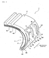
- FIG. 1 is a partially notched perspective view of a run-flat tire
- FIG. 2 is a sectional view of the main portion of the run-flat tire
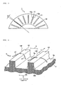
- FIG. 3 is a partial side view of the run-flat tire
- FIG. 4 is a perspective view illustrating a state in which a turbulent flow is created by a turbulent flow-creating ridge
- FIG. 5 is a side view illustrating the state in which the turbulent flow is created by the turbulent flow-creating ridge
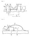
- FIG. 6 is a side view illustrating the flow of a turbulent flow in detail.
- a run-flat tire 1 as a tire includes a tread portion 2 that contacts a road surface, a tire side portion 3 on each of both sides of the tire, and a bead portion 4 provided along the opening edge of each of the tire side portion 3.
- the bead portion 4 includes a bead core 6A and a bead filler 6B provided so as to circulate along the edge portion of the opening portion of the tire side portion 3.
- a bead wire or the like is specifically used as the bead core 6A.
- a carcass layer 7 serving as the skeleton of the tire.
- a side-reinforcing layer 8 for reinforcing the tire side portion 3 is provided inside (inside the width direction of the tire) the carcass layer 7 positioned at the tire side portion 3.
- the side-reinforcing layer 8 is formed of a crescent-shaped rubber composition in a section in the width direction of the tire.
- a tire of the present invention can exert any such action or effect as described above by using, in the side-reinforcing layer 8, a rubber composition of the present invention containing a modified conjugated diene-based polymer that excellently interacts with carbon black and has low rolling property.
- a plurality of belt layers (steel belt reinforcing layers 9A and 9B, and a circumferential direction reinforcing layer 9C).
- An outside surface 3a as the tire surface of each tire side portion 3 is provided with turbulent flow-creating ridges 10, which extend from an inner circumference side to an outer circumference side, at an equal interval in the circumferential direction of the tire.
- each tire side portion 3 is provided with the turbulent flow-creating ridges 10, which extend from the inner circumference side to the outer circumference side, at an equal interval in the circumferential direction of the tire.
- the modified conjugated diene-based polymer to be compounded into the rubber composition to be used in the side-reinforcing layer 8 of the tire of the present invention has the following feature.
- the polymer is obtained by: introducing a primary amino group or a precursor capable of producing a primary amino group through hydrolysis to a terminal of a conjugated diene-based polymer through a modification reaction between the terminal and an alkoxysilane compound having the primary amino group or the precursor capable of producing a primary amino group through hydrolysis; and adding a condensation-accelerating agent to the modification reaction system during and/or after the completion of the modification reaction.
- the primary amino group is produced as described below.
- the precursor capable of producing a primary amino group through hydrolysis is introduced in a state before hydrolysis (that is, a protected state) to the terminal through the modification reaction, and is subjected to, for example, a desolvation treatment or water treatment involving using steam such as steam stripping after the completion of the modification reaction or is intentionally hydrolyzed to produce the primary amino group.
- a desolvation treatment or water treatment involving using steam such as steam stripping after the completion of the modification reaction or is intentionally hydrolyzed to produce the primary amino group.
- a modified conjugated diene-based polymer modified with an alkoxysilane compound free of any primary amino group interacts with silica to a high degree
- the polymer has low reinforcing property on carbon black because the polymer interacts with the carbon black to a low degree.
- the modified conjugated diene-based polymer modified with the alkoxysilane compound having a primary amino group has high reinforcing property on the carbon black because the primary amino group and the carbon black interact with each other to a high degree.
- molecules of a modified conjugated diene-based polymer modified with an alkoxysilane compound generally react with each other to have an increased molecular weight, which increases the viscosity of an unvulcanized rubber composition to deteriorate its processability.
- such modified conjugated diene-based polymer modified with the alkoxysilane compound having a primary amino group according to the present invention that the condensation-accelerating agent is added to the reaction system during and/or after the completion of the modification reaction and a condensation reaction is advanced in the presence of steam or water does not increase the viscosity of the unvulcanized rubber composition to deteriorate its processability because an excessive increase in the molecular weight of the modified conjugated diene-based polymer is prevented.
- the rubber composition according to the present invention must contain 10 mass% or more of the modified conjugated diene-based polymer in 100 parts by mass of the rubber components. As long as the content of the modified conjugated diene-based polymer in 100 parts by mass of the rubber components is 10 mass% or more, the low heat generating property of the rubber composition is exerted, and hence durability at the time of run-flat running and rolling resistance at the time of normal running are improved. In order that the low heat generating property of the rubber composition may be additionally improved, the content of the modified conjugated diene-based polymer is more preferably 52 mass% or more, particularly preferably 55 mass% or more in 100 parts by mass of the rubber components.
- the conjugated diene-based polymer according to the present invention is obtained by polymerizing a conjugated diene compound alone or by copolymerizing the conjugated diene compound and an aromatic vinyl compound.
- a production method for the polymer is not particularly limited, and any one of a solution polymerization method, a vapor phase polymerization method, and a bulk polymerization method can be employed. Of those, the solution polymerization method is particularly preferred.
- a polymerization type may be any one of a batch type and a continuous type. Of those, the batch type is desirable in order that a molecular weight distribution may be narrowed.
- the conjugated diene-based polymer preferably has a glass transition temperature of -30°C or less.
- the conjugated diene compound includes, for example, 1,3-butadiene, isoprene, 1,3-pentadiene, 2,3-dimethyl-1,3-butadiene, 2-phenyl-1,3-butadiene, 1, 3-hexadiene and the like. They may be used alone or in combination of two or more kinds thereof. Of those, 1,3-butadiene is particularly preferred.
- the aromatic vinyl compound used in copolymerization with the conjugated diene copolymer includes, for example, styrene, a -methylstyrene, 1-vinylnaphthalene, 3-vinyltoluene, ethylvinylbenzene, divinylbenzene, 4-cyclohexylstyrene, and 2,4,6-trimethylstyrene. They may be used alone or in combination of two or more kinds thereof. Of those, styrene is particularly preferred.
- the primary amino group or the precursor capable of producing a primary amino group through hydrolysis may be introduced through a reaction between a terminal of a living conjugated diene-based polymer in such a state that a polymerization reaction is not terminated (which may hereinafter be referred to as "active terminal") and a modifying agent
- the polymer to be used is preferably such that at least 10% of its polymer chain has living property or pseudo-living property.
- a polymerization reaction having such living property is, for example, a reaction in which the conjugated diene compound alone is, or the conjugated diene compound and the aromatic vinyl compound are, subjected to anionic polymerization in an organic solvent with an alkali metal compound as an initiator, or a reaction in which the conjugated diene compound alone is, or the conjugated diene compound and the aromatic vinyl compound are, subjected to coordination anionic polymerization with a catalyst containing a lanthanum series rare earth element compound.
- a lithium compound is preferably used as the alkali metal compound to be used as the initiator for the anionic polymerization described above.
- a hydrocarbyllithium and a lithium amide compound are preferably used.
- the hydrocarbyllithium is used, a conjugated diene-based polymer having a hydrocarbyl group at a polymerization-initiating terminal and a polymerization active site at the other terminal is obtained.
- the lithium amide compound a conjugated diene-based polymer having a nitrogen-containing group at a polymerization-initiating terminal and a polymerization active site at the other terminal is obtained.
- the hydrocarbyllithium is preferably a compound having a hydrocarbyl group having 2 to 20 carbon atoms.
- Examples thereof include ethyllithium, n-propyllithium, isopropyllithium, n-butyllithium, sec-butyllithium, tert-octyllithium, n-decyllithium, phenyllithium, 2-naphthyllithium, 2-butylphenyllithium, 4-phenylbutyllithium, cyclohexyllithium, cyclopentyllithium, and a reaction product of diisopropenylbenzene with butyllithium.
- n-butyllithium is particularly suited.
- the lithium amide compound includes, for example, lithium hexamethyleneimide, lithium pyrrolidide, lithium piperidide, lithium heptamethyleneimide, lithium dodecamethyleneimide, lithium dimethylamide, lithium diethylamide, lithium dipropylamide, lithium dibutylamide, lithium dihexylamide, lithium diheptylamide, lithium dioctylamide, lithium di-2-ethylhexylamide, lithium didecylamide, lithium-N-methylpiperazide, lithium ethylpropylamide, lithium ethylbutylamide, lithium methylbutylamide, lithium ethylbenzylamide, lithium methylphenethylamide, N-lithiomorpholine, N-methyl-N'-lithiohomopiperazine, N-ethyl-N'-lithiohomopiperazine, and N-butyl-N'-lithiohomopiperazine.
- cyclic lithium amides such as lithium hexamethyleneimide, lithium pyrrolidide, lithium piperidide, lithium heptamethyleneimide, and lithium dodecamethyleneimide are preferred, and lithium hexamethyleneimide and lithium pyrrolidide are particularly preferred.
- the lithium amide compound is produced in advance in the presence of such solubilizing component (SOL) as disclosed in JP 06-206920 A or in the absence of any solubilizing component as disclosed in JP 06-199922 A , and then the compound can be used as a polymerization initiator.
- SOL solubilizing component
- the lithium amide compound is produced in a polymerization system (in situ) without any preliminary adjustment, and the compound can be used as a polymerization initiator.
- the use amount of the polymerization initiator is preferably selected in the range of 0.2 to 20 mmol per 100 g of the monomer.
- a conjugated diene compound or a mixture of a conjugated diene compound and an aromatic vinyl compound is anionically polymerized in the presence of the lithium compound serving as a polymerization initiator and a randomizer used in accordance with needs, thereby producing a conjugated diene-based polymer of interest having an active terminal.
- the lithium compound is used as the polymerization initiator, not only the conjugated diene-based polymer having an active terminal but also the copolymer of the conjugated diene compound having an active terminal and the aromatic vinyl compound can be obtained with higher efficiency than that in the case where the catalyst containing a lanthanum series rare earth element compound described above is used.
- the hydrocarbon-based solvent is preferably a hydrocarbon having 3 to 8 carbon atoms.
- Examples thereof include propane, n-butane, isobutane, n-pentane, isopentane, n-hexane, cyclohexane, propene, 1-butene, isobutene, trans-2-butene, cis-2-butene, 1-pentene, 2-pentene, 1-hexene, 2-hexene, benzene, toluene, xylene, ethylbenzene, methylcyclopentane, and methylcyclohexane. They may be used alone or in combination of two or more kinds thereof.
- a monomer concentration in the solvent is preferably 5 to 50 mass%, more preferably 10 to 30 mass%. It should be noted that, when copolymerization is carried out with the conjugated diene compound and the aromatic vinyl compound, the content of the aromatic vinyl compound in a mixture of the loaded monomers is preferably in the range of 55 mass% or less.
- the randomizer which may be used in accordance with needs, is a compound which is capable of controlling a microstructure of a conjugated diene-based polymer such as increasing 1,2-bonds of the butadiene moieties in a butadiene-styrene copolymer or 3,4-bonds in an isoprene polymer or controlling the monomer unit composition distribution in a conjugated diene compound-aromatic vinyl compound copolymer such as randomizing butadiene units and styrene units in a butadiene-styrene copolymer.
- No particular limitation is imposed on the type of the randomizer, and any of known compounds conventionally used as a randomizer may appropriately employed.
- the randomizer include ethers and tertiary amines such as dimethoxybenzene, tetrahydrofuran, dimethoxyethane, diethylene glycol dibutyl ether, diethylene glycol dimethyl ether, oxolanylpropane oligomers [in particular, those including 2,2-bis(2-tetrahydrofuryl)-propane], triethylamine, pyridine, N-methylmorpholine, N,N,N',N'-tetramethylethylenediamine, and 1,2-piperidinoethane.
- potassium salts such as potassium t-amylate and potassium t-butoxide and sodium salts such as sodium t-amylate may also be employed.
- randomizers may be used alone or in combination of two or more kinds thereof.
- the use amount of the randomizer is preferably selected in the range of 0.01 to 1000 mole equivalents per mole of the lithium compound.
- the temperature of the polymerization reaction is preferably selected in the range of 0 to 150°C, more preferably 20 to 130°C.
- the polymerization reaction may be carried out under generated pressure, but generally desirably performed under such pressure that the monomer is maintained virtually as a liquid phase. That is, a higher pressure may be employed in accordance with needs, although depending on the individual substances to be polymerized, and the polymerization solvent and polymerization temperature to be used. Such pressure may be obtained through an appropriate method such as applying pressure to a reactor by use of gas inert to the polymerization reaction.
- a modifying agent to be described later is preferably added to the polymer having an active terminal thus obtained in a stoichiometric amount or an amount exceeding the amount with respect to the active terminal of the polymer so that the modifying agent may be caused to react with the active terminal bonded to the polymer.
- An alkoxysilane compound having a precursor capable of producing a primary amino group through hydrolysis is used as a modifying agent for efficiently introducing a primary amino group to the active terminal.
- Examples of the compound may include N,N-bis(trimethylsilyl)aminopropylmethyldimethoxysilane, 1-trimethylsilyl-2,2-dimethoxy-1-aza-2-silacyclopentane, N,N-bis(trimethylsilyl)aminopropyltrimethoxysilane, N,N-bis(trimethylsilyl)aminopropyltriethoxysilane, N,N-bis(trimethylsilyl)aminopropylmethyldiethoxysilane, N,N-bis(trimethylsilyl)aminoethyltrimethoxysilane, N,N-bis(trimethylsilyl)aminoethyltriethoxysilane, N,N-bis(trimethylsilyl)aminoethylmethyldimethoxysilane, and N,N-bis(trimethylsilyl)aminoethylmethyldiethoxysilane.
- N,N-bis(trimethylsilyl)aminopropylmethyldimethoxysilane N,N-bis(trimethylsilyl)aminopropylmethyldiethoxysilane, or 1-trimethylsilyl-2,2-dimethoxy-1-aza-2-silacyclopentane is preferred.
- modifying agents may be used alone, or two or more kinds thereof may be used in combination.
- the modifying agent may be a partial condensation product.
- the partial condensation product is a compound prepared by converting a part (not all) of SiOR in the modifying agent to a SiOSi bond by condensation.
- the use amount of the modifying agent is preferably 0.5 to 200 mmol/kg (conjugated diene-based polymer) .
- the use amount is more preferably 1 to 100 mmol/kg (conjugated diene-based polymer), particularly preferably 2 to 50 mmol/kg (conjugated diene-based polymer).
- the "conjugated diene-based polymer” means the mass of polymer not containing additives such as an age resistor added during or after the production.
- the modifying agent may be bonded to any of a polymerization-initiating terminal, a polymerization-terminating terminal, or other than those, a polymer main chain, and a polymer side chain. From the viewpoint of improvement of the low heat generating property by preventing energy loss from a polymer terminal, the modifying agent is preferably introduced into the polymerization-initiating terminal or the polymerization-terminating terminal.
- a specific condensation-accelerating agent is preferably used for accelerating the condensation reaction in which the alkoxysilane compound having a precursor capable of producing a primary amino group through hydrolysis to be used as the modifying agent is involved.
- a compound containing a tertiary amino group or an organic compound containing one or more kinds of elements each belonging to any one of Groups 3, 4, 5, 12, 13, 14, and 15 of the periodic table can be used as such condensation-accelerating agent.
- the condensation-accelerating agent is preferably an alkoxide, carboxylate, trialkylsiloxane, or acetylacetonato complex salt containing at least one kind of metal selected from the group consisting of titanium (Ti), zirconium (Zr), bismuth (Bi), aluminum (Al), and Tin (Sn).
- the condensation-accelerating agent employed in the above case may be added to the reaction system before the modification reaction. However, preferably, the agent is added to the modification reaction system during and/or after the completion of the modification reaction. When the agent is added before the modification reaction, in some cases, the agent directly reacts with the active terminal, thereby failing to introduce a hydrocarbyloxy group having a precursor capable of producing a primary amino group through hydrolysis to the active terminal.
- the time at which the condensation-accelerating agent is added is generally 5 minutes to 5 hours after the initiation of the modification reaction, preferably 15 minutes to 1 hour after the initiation of the modification reaction.
- condensation-accelerating agent examples include an alkoxide, carboxylate, and acetylacetonato complex salt of titanium (Ti).
- condensation-accelerating agent examples include tetrakis(2-ethyl-1,3-hexanediolato)titanium, tetrakis(2-methyl-1,3-hexanediolato)titanium, tetrakis(2-propyl-1,3-hexanediolato)titanium, tetrakis(2-butyl-1,3-hexanediolato)titanium, tetrakis(1,3-hexanediolato)titanium, tetrakis(1,3-pentanediolato)titanium, tetrakis(2-methyl-1,3-pentanediolato)titanium, tetrakis(2-ethyl-1,3-pentanediolato)titanium, tetrakis(2-propyl-1,3-pentanediolato)titanium, tetrakis(2-
- tetrakis(2-ethyl-1,3-hexanediolato)titanium tetrakis(2-ethylhexoxy)titanium, and titanium di-n-butoxide(bis-2,4-pentanedionate) are preferred.
- condensation-accelerating agent examples include tris (2-ethylhexanoato)bismuth, tris(laurato)bismuth, tris(naphthenato)bismuth, tris(stearato)bismuth, tris(oleato)bismuth, tris(linolato)bismuth, tetraethoxyzirconium, tetra-n-propoxyzirconium, tetra-isopropoxyzirconium, tetra-n-butoxyzirconium, tetra-sec-butoxyzirconium, tetra-tert-butoxyzirconium, tetra(2-ethylhexyl)zirconium, zirconium tributoxystearate, zirconium tributoxyacetylacetonate, zirconium dibutoxy bis(acetylacetonate), zirconium tributoxyethylacetoacetate
- Further examples include triethoxyaluminum, tri-n-propoxyaluminum, triisopropoxyaluminum, tri-n-butoxyaluminum, tri-sec-butoxyaluminum, tri-tert-butoxyaluminum, tri(2-ethylhexyl) aluminum, aluminum dibutoxystearate, aluminum dibutoxyacetylacetonate, aluminum butoxybis(acetylacetonate), aluminum dibutoxyethylacetoacetate, aluminumtris(acetylacetonate), aluminumtris(ethylacetoacetate), tris(2-ethylhexanoato)aluminum, tris(laurato)aluminum, tris(naphthenato)aluminum, tris(stearato)aluminum, tris(oleato)aluminum, and tris(linolato)aluminum.
- examples of the tin-based condensation accelerator suitably include dicarboxylic acid salts ⁇ in particular, a bis(hydrocarbylcarboxylic acid)salt ⁇ of divalent tin, dicarboxylic acid salts (including a ⁇ bis(hydrocarbylcarboxylic acid) ⁇ salt) of dihydrocarbyltin of tetravalent tin, bis ( ⁇ -diketonate), alkoxy halides, and monocarboxylic acid salt hydroxides. Specifically, bis(2-ethylhexanoate)tin and the like are given.
- a titanium compound is preferred, and an alkoxide of titanium metal, a carboxylate of titanium metal, or an acetylacetonato complex salt of titanium metal is particularly preferred.
- the use amount of the condensation-accelerating agent is preferably such that the mole ratio of the compounds described above to the total amount of hydrocarbyloxy groups present in the reaction system is 0.1 to 10, particularly preferably 0.5 to 5. Through controlling the use amount of the condensation-accelerating agent so as to fall within the range, the condensation reaction efficiently proceeds.
- the condensation reaction in the present invention progresses in the presence of the above-mentioned condensation-accelerating agent and steam or water.
- steam for example, a desolvation treatment based on steam stripping is performed, and the condensation reaction progresses during the steam stripping.
- condensation reaction may be carried out in a system in which water is dispersed as drop in an organic solvent or in an aqueous solution at a condensation reaction temperature of preferably 20 to 180°C, more preferably 30 to 170°C, even more preferably 50 to 170°C, particularly preferably 80 to 150°C.
- the condensation reaction can be efficiently completed, whereby deterioration in quality and the like of the produced modified conjugated diene-based polymer because of time-dependent aging reaction of the polymers and the like can be prevented.
- the condensation reaction time is generally about 5 minutes to 10 hours, preferably about 15 minutes to 5 hours. Through controlling the condensation reaction time to fall within the range, the condensation reaction can be smoothly completed.
- the pressure of the reaction system during the condensation reaction is generally 0.01 to 20 MPa, preferably 0.05 to 10 MPa.
- condensation reaction is performed in an aqueous solution
- a batch-type reactor may be employed.
- the reaction may be carried out in a continuous manner by means of an apparatus such as a multi-step continuous reactor. In the course of the condensation reaction, desolvationmaybe simultaneously performed.
- the primary amino group derived from the modifying agent for each of the modified conjugated diene-basedpolymer of the present invention is produced by performing a hydrolysis treatment as described above. That is, the protective group on the primary amino group is transformed into a free primary amino group by hydrolyzing the precursor capable of producing a primary amino group through hydrolysis.
- the hydrolysis treatment of the precursor capable of producing a primary amino group through hydrolysis derived from the modifying agent can be performed at any one of the stages commencing on a stage involving the condensation treatment and ending on a stage involving performing desolvation to provide a dry polymer as required, provided that the precursor capable of producing a primary amino group of the modified conjugated diene-based polymer may not be subjected to a hydrolysis treatment by the above-mentioned reason.
- an alkoxysilane-modified butadiene-based polymer not subjected to the above-mentioned condensation reaction produces a relatively large amount of a VOC.
- the alkoxysilane-modified butadiene-based polymer obtained by the condensation reaction according to the invention of the application has such good step workability as described below because the production of the volatile organic compound (VOC) can be reduced: pores are hardly produced in an extrusion step. At the same time, the polymer imposes a small load on an environment.
- a general age resistor for example, a phenol-based age resistor such as N-(1,3-dimethylbutyl)-N'-phenyl-p-phenylenediamine
- a general age resistor for example, a phenol-based age resistor such as N-(1,3-dimethylbutyl)-N'-phenyl-p-phenylenediamine
- the modified conjugated diene-based polymer obtained as described above has a Mooney viscosity (ML 1+4 , 100°C) of preferably 10 to 150, more preferably 15 to 100.
- Mooney viscosity preferably 10 to 150, more preferably 15 to 100.
- Mooney viscosity is 10 or more, rubber physical properties typified by a fracture resistance characteristic are sufficiently obtained.
- Mooney viscosity is 150 or less, the workability becomes additionally good, which makes it additionally easy to knead the polymer with a compounding agent.
- the unvulcanized rubber composition according to the present invention compounded with the modified conjugated diene-based polymer has a Mooney viscosity (ML 1+4 , 130°C) of preferably 10 to 150, more preferably 15 to 100.
- the modified conjugated diene-based polymer to be used in the rubber composition according to the present invention has a ratio (Mw) / (Mn) of a weight-average molecular weight (Mw) in terms of polystyrene to a number-average molecular weight (Mn) before the modification measured by gel permeation chromatography of preferably 1.02 to 2.0, more preferably 1.02 to 1.5.
- the term "before the modification” refers to the case where isolation is performed in accordance with an ordinary method before an active terminal of an unmodified conjugated diene-based polymer and a polymerization terminator or the modifying agent are caused to react with each other.
- theordinarymethod is, for example, asdescribed below.
- the unmodified conjugated diene-based polymer has only to be drawn in an amount needed for the measurement from a polymerization reaction liquid.
- the modified conjugated diene-based polymer used in the rubber composition according to the present invention has a number-average molecular weight (Mn) before the modification of preferably 100,000 to 500,000, more preferably 120,000 to 300,000. Setting the number-average molecular weight of the modified conjugated diene-based polymer before the modification within the range suppresses a reduction in elastic modulus of a vulcanized product and an increase in hysteresis loss. As a result, an excellent rupture resistant characteristic is obtained. In addition, excellent kneading workability of the rubber composition containing the modified conjugated diene-based polymer is obtained.
- Mn number-average molecular weight
- modified conjugated diene-basedpolymer may be used in the rubber composition according to the present invention, or two or more kinds of such polymers may be used in combination.
- a rubber component to be used in combination with the modified conjugated diene-based polymer is, for example, a natural rubber or any other diene-based synthetic rubber.
- Examples of the other diene-based synthetic rubber include a styrene-butadiene copolymer (SBR), a polybutadiene (BR), a polyisoprene (IR), a styrene-isoprene copolymer (SIR), an isobutylene-isoprene rubber (IIR), a halogenated butyl rubber, an ethylene-propylene-diene terpolymer (EPDM), and a mixture thereof.
- SBR styrene-butadiene copolymer
- BR polybutadiene
- IR polyisoprene
- SIR styrene-isoprene copolymer
- IIR isobutylene-isoprene rubber
- EPDM ethylene-propylene-diene terpolymer
- Carbon black having a nitrogen adsorption specific surface area (N 2 SA) of 20 to 90 m 2 /g is used as a reinforcing filler in the rubber composition according to the present invention.
- the carbon black include GPF, FEF, SRF, and HAF.
- the nitrogen adsorption specific surface area of the carbon black is preferably 25 to 90 m 2 /g, particularly preferably 35 to 90 m 2 /g.
- Such carbon black is compounded in an amount of 10 to 100 parts by mass, preferably 30 to 90 parts by mass with respect to 100 parts by mass of the rubber components. The use of the carbon black in such amount exerts large improving effects on various physical properties.
- the HAF and the FEF are particularly preferred because of their excellent fracture resistance characteristics and excellent low heat generating properties (low fuel consumption properties).
- the low heat generating property (low fuel consumption property) of a composition containing the carbon black is improved as the nitrogen adsorption specific surface area of the carbon black reduces.
- the carbon black is used in combination with the modified conj ugated diene-based polymer according to the present invention obtained by introducing the primary amino group to the active terminal and adding the condensation-accelerating agent to the modification reaction system during and/or after the completion of the modification reaction, the following feature is obtained.
- the rubber composition according to the present invention becomes excellent in low heat generating property (low fuel consumption property) and fracture resistance characteristic as the nitrogen adsorption specific surface area reduces even when the effect of the carbon black is not taken into consideration.
- the rubber composition according to the present invention is sulfur-crosslinkable, and hence sulfur is used as a vulcanizing agent.
- sulfur is preferably compounded in an amount of 1 to 10 parts by mass with respect to 100 parts by mass of the rubber components. This is because of the following reasons. When the amount is less than 1 part by mass, the number of crosslinks is insufficient, and hence the fracture resistance characteristic deteriorates in some cases. When the amount exceeds 10 parts by mass, the heat resistance of the composition may deteriorate. From the foregoing viewpoint, sulfur is particularly preferably compounded in an amount of 2 to 8 parts by mass.
- the rubber composition according to the present invention may further contain, in accordance with needs, a variety of chemicals usually used in the rubber industry.
- the chemicals include a vulcanizing agent other than sulfur, a vulcanization-accelerating agent, a process oil, an age resistor, a scorch preventive, zinc white, stearic acid, a thermosetting resin, and a thermoplastic resin.
- the vulcanization-accelerating agent which can be used in the present invention is not specifically restricted, and may include, for example, thiazole-based vulcanization-accelerating agents such as M (2-mercaptobenzothiazole), DM (dibenzothiazyl disulfide), and CZ (N-cyclohexyl-2-benzothiazylsulfenamide), and guanidine-based vulcanization-accelerating agents such as DPG (diphenylguanidine).
- the use amount thereof is preferably 0.1 to 6.0 parts by mass, more preferably 0.2 to 4.0 parts by mass with respect to 100 parts by mass of the rubber component.
- the process oil which can be used as a softening agent in the rubber composition according to the present invention includes, for example, a paraffin-based oil, a naphthene-based oil, and an aromatic-based oil.
- the aromatic-based oil is used for uses in which the tensile strength and the abrasion resistance are regarded as important, and the naphthene-based oil or the paraffin-based oil is used for uses in which the hysteresis loss and the low-temperature characteristic are regarded as important.
- the use amount thereof is preferably 0 to 50 parts by mass with respect to 100 parts by mass of the rubber component, and when the amount is 50 parts by mass or less, deterioration in the tensile strength and the low heat generating property (low fuel consumption property) of the vulcanized rubber is suppressed.
- an age resistor that can be used in the rubber composition according to the present invention is, for example, 3C(N-isopropyl-N'-phenyl-p-phenylenediamine, 6C[N-(1,3-dimethylbutyl)-N'-phenyl-p-phenylenediamine], AW(6-ethoxy-2,2,4-trimethyl-1,2-dihydroquinoline), or a high-temperature condensation product of diphenylamine and acetone.
- the use amount of the age resistor is preferably 0.1 to 5.0 parts by mass, more preferably 0.3 to 4.0 parts by mass with respect to 100 parts by mass of the rubber component.
- the turbulent flow-creating ridges 10 are each such that a sectional shape cut out in a direction A perpendicular to the direction in which the ridge extends is a left-right symmetrical shape.
- the turbulent flow-creating ridges 10 each have an edge portion 10E when viewed in a section in the radial direction.
- the turbulent flow-creating ridges 10 each have an edge portion 10F when viewed in a section in the circumferential direction.
- a front wall angle ⁇ 1 of each of front wall surfaces 10a of the turbulent flow-creating ridges 10 on which an air flow impinges with respect to the outside surface 3a as the tire surface is set to fall within the range of 70° to 110°. It should be noted that the figures illustrate turbulent flow-creating ridges each having a quadrangular sectional shape and a front wall angle of 90°.
- a rear wall angle ⁇ 2 of each of rear wall surfaces 10b of the turbulent flow-creating ridges 10 with respect to the outside surface 3a is preferably set so as to be equal to the front wall angle ⁇ 1 because the sectional shape of each of the ridges cut out in the direction A perpendicular to its extending direction has left-right symmetry.
- a lower side width w of each of the turbulent flow-creating ridges 10 in the direction A perpendicular to the extending direction be set to fall within the range of 0.5 mm to 5 mm.
- the turbulent flow-creating ridges 10 are preferably set as sites for causing a turbulent flow to flow through failed sites, the ridges having such dimensions that when the height, pitch, and lower side width of each of the ridges are represented by h, p, and w, respectively, the relationships of 1.0 ⁇ p/h ⁇ 50.0 and 1. 0 ⁇ (p-w) /w ⁇ 100.0 are satisfied.
- a value for the p/h preferably falls within the range of 2.0 ⁇ p/h ⁇ 24.0, more preferably falls within the range of 10.0 ⁇ p/h ⁇ 20.0.
- a value for the (p-w) /w more preferably falls within the range of 4.0 ⁇ (p-w)/w ⁇ 39.0.
- the ridge height h preferably falls within the range of 0.5 mm ⁇ h ⁇ 7 mm
- the lower side width w preferably falls within the range of 0.3 mm ⁇ w ⁇ 4 mm.
- the vertical turbulent flow state of the air flow can be roughly coordinated with the p/h.
- the pitch p is excessively narrow, the air flow does not impinge as a downward flow on the tire surface between the turbulent flow-creating ridges.
- the case where the pitch p is excessively wide is identical to the case where there are no turbulent flow-creating ridges.
- the (p-w) /w represents a ratio of the width w of each of the turbulent flow-creating ridges to the pitch p.
- the case where the ratio is excessively small is identical to the case where a ratio of the surface areas of the turbulent flow-creating ridges to the area of a surface where one wishes to improve heat radiation is one.
- the minimum value for the (p-w)/w is specified as 1.0 because the turbulent flow-creating ridges are each formed of rubber and hence a heat radiation-improving effect cannot be expected from an increase in their surface areas.
- a tilt angle ⁇ of each turbulent flow-creating ridge with respect to the radial direction of the tire preferably falls within the range of -70° ⁇ 70° (see FIG. 3 ).
- the tilt angle ⁇ more preferably falls within the range of -30° ⁇ 30°.
- the flowof the turbulent flow flowing over the outer peripheral surface 3a is described in detail.
- the air flow a turns into a vertical turbulent flow al that ascends at the position of each turbulent flow-creating ridge 10 and descends at a position where the turbulent flow-creating ridge 10 is absent.
- the front wall angle ⁇ 1 of each turbulent flow-creating ridge 10 is less than 70°, the vertical turbulent flow al is trapped in a recessed portion and the amount of a flow to be lifted upward is small.
- a separation angle ⁇ of the flow with respect to the turbulent flow-creating ridge 10 becomes small, and hence only a moderate downward flow is created on the downstream side of the turbulent flow-creating ridge 10.
- each turbulent flow-creating ridge 10 exceeds 110°, the separation angle ⁇ of the vertical turbulent flow al with respect to the turbulent flow-creating ridge 10 and its flow velocity become small.
- the flowvelocity of the flow to be lifted upward becomes slow, and hence vertical heat exchange cannot be promoted. Therefore, effective heat exchange with the outside surface 3a cannot be promoted.
- each turbulent flow-creating ridge 10 falls within the range of 70° to 110°, the separation angle ⁇ of the vertical turbulent flow al with respect to the turbulent flow-creating ridge 10 is somewhat large, and hence the flow returns as a vigorous downward flow on the downstream side of the turbulent flow-creating ridge 10 to impinge on the outside surface 3a. As a result, active heat exchange with the outside surface 3a is performed. As can be seen from the foregoing, a reduction in tire temperature can be achieved with the turbulent flow-creating ridges 10 provided for the outside surface 3a with reliability, and the durability of the tire can be improved.
- the lower side width w of each turbulent flow-creating ridge 10 in the direction A perpendicular to its extending direction is set to fall within the range of 0.5 mm to 5 mm.
- the turbulent flow-creating ridge 10 has so weak a strength as to vibrate owing to the air flow.
- the lower side width w of the turbulent flow-creating ridge 10 exceeds 5 mm, the quantity of heat accumulated in the turbulent flow-creating ridge 10 becomes excessively large.
- setting the lower side width w of the turbulent flow-creating ridge 10 within the range of 0.5 mm to 5 mm can improve a heat-radiating characteristic while preventing a demerit caused by providing the tire side portion 3 with the turbulent flow-creating ridges 10 to the extent possible.
- the turbulent flow-creating ridge 10 can be caused to exert a predetermined heat-radiating characteristic in the run-flat tire 1 of any tire size.
- each turbulent flow-creating ridge 10 may be caused to exert a sufficient heat-radiating effect
- it is important that the turbulent flow-creating ridge 10 has a ridge height comparable to the thickness of a velocity boundary layer (layer having a slow velocity on a wall surface) at the place where the ridge is placed. In this case, a sufficient fluid-mixing action is exerted.
- the thickness of the velocity boundary layer is specified by the square root of the tire radius. Accordingly, a ratio between the square root and the ridge height can be an indicator of the heat-radiating effect.
- each turbulent flow-creating ridge 10 cut out in the direction A perpendicular to its extending direction is a left-right symmetrical shape. Therefore, the turbulent flow-creating ridge 10 is such that left and right distances from the central position in the sectional shape cut out in the direction A perpendicular to the extending direction to the surface of the turbulent flow-creating ridge 10 become uniform. Accordingly, the heat accumulation in the turbulent flow-creating ridge 10 can be reduced to the extent possible.
- each turbulent flow-creating ridge 10 when the height, pitch, and lower side width of each turbulent flow-creating ridge 10 are represented by h, p, and w, respectively, the h, the p, and the w are set to satisfy the relationships of 1.0 ⁇ p/h ⁇ 50.0 and 1.0 ⁇ (p-w)/w ⁇ 100.0. This is because of the following reason.
- the turbulent flow state of the air flow can be roughly coordinated with the p/h.
- the pitch p is excessively narrow, the air flow does not impinge as a downward flow on the outside surface 3a between the turbulent flow-creating ridges 10.
- the case where the pitch p is excessively wide is identical to the case where the turbulent flow-creating ridges 10 are absent.
- the (p-w)/w represents a ratio of the lower side width w of each turbulent flow-creating ridge 10 to the pitch p.
- the case where the ratio is excessively small is identical to the case where a ratio of the surface areas of the turbulent flow-creating ridges 10 to the area of a surface where one wishes to improve heat radiation is one.
- the minimum value for the (p-w) /w is specified as 1.0 because the turbulent flow-creating ridges 10 are each formed of rubber and hence a heat radiation-improving effect cannot be expected from an increase in their surface areas.
- the tilt angle ⁇ of each turbulent flow-creating ridge 10 with respect to the radial direction r of the tire falls within the range of -70° ⁇ 70°.
- the air flow a relatively created by the rotating tire impinges on the surface of each turbulent flow-creating ridge 10 in the circumferential direction of the tire with reliability, and hence the above-mentioned heat-radiating effect by a turbulent flow can be expected.
- the present invention is applied to the run-flat tire 1 in which the tire side portion 3 is provided with the side-reinforcing layer 8 using the rubber composition containing the modified conjugated diene-based polymer described above and the turbulent flow-creating ridges.
- the side-reinforcing layer 8 enables run-flat running, and the run-flat tire to which both the layer and the ridges are applied can reduce an increase in the temperature of a failure core at the time of the running to the extent possible.
- the turbulent flow-creating ridges 10 each have the edge portion 10E when viewed in the section in the radial direction. Accordingly, a separating action is exerted on an air flow that flows in association with the rotation of the run-flat tire 1 from an inner diameter side to an outer diameter side with the aide of a centrifugal force. Then, the separated air flow turns into a downward flow to impinge on the tire side portion 3, thereby promoting heat exchange.
- the turbulent flow-creating ridges 10 each have the edge portion 10F when viewed in a section in the circumferential direction.
- the air flow surmounts each turbulent flow-creating ridge 10 in association with the rotation of the run-flat tire 1, the air flow is easily separated from the tire side portion 3.
- the air flow that has once been separated from the tire side portion 3 turns into a turbulent flow that abruptly descends by virtue of a negative pressure generated on the rear side (downstream side) of the turbulent flow-creating ridge 10 in the rotation direction of the tire to impinge on the tire side portion 3, the turbulent flow having a promoting action on heat exchange with the tire side portion 3.
- FIG. 7 illustrates a turbulent flow-creating ridge 10A as a first modified example.
- the sectional shape of the turbulent flow-creating ridge 10A cut out in the directionAperpendicular to its extending direction is a reverse trapezoidal shape, and both the front wall angle 0 1 and the rear wall angle ⁇ 2 are angles of less than 90°.
- the turbulent flow-creating ridge 10A is formed into a trapezoidal shape by making both the front wall angle ⁇ 1 and the rear wall angle ⁇ 2 angles in excess of 90°, the occurrence of a crack due to the deterioration of a corner portion of the turbulent flow-creating ridge 10A can be prevented to the extent possible.
- FIG. 8 illustrates a turbulent flow-creating ridge 10B as a second modified example.
- the sectional shape of the turbulent flow-creating ridge 10B cut out in the direction A perpendicular to its extending direction is a triangular shape.
- a rubber usage can be curtailed while the rigidity of the turbulent flow-creating ridge 10B is maintained by securing the dimension of the lower side width w.
- FIG. 9 illustrates a turbulent flow-creating ridge 10C as a third modified example.
- the sectional shape of the turbulent flow-creating ridge 10C cut out in the direction A perpendicular to its extending direction is a stepped shape.
- a rubber usage can be curtailed while the rigidity of the turbulent flow-creating ridge 10C is maintained by securing the dimension of the lower side width w.
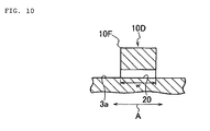
- FIG. 10 illustrates a turbulent flow-creating ridge 10D as a fourth modified example.
- the sectional shape of the turbulent flow-creating ridge 10D cut out in the direction A perpendicular to its extending direction is a rectangular shape, and the ridge has a through-hole 20 in the directionAperpendicular to the extending direction.
- the turbulent flow-creating ridge 10D is provided with the through-hole 20, an air flow flows into the through-hole 20, and hence heat in the turbulent flow-creating ridge 10D can be radiated. Therefore, heat accumulation in the turbulent flow-creating ridge 10D can be reduced to the extent possible.
- the turbulent flow-creating ridges 10 are provided over the entire circumference of the tire side portion 3 in the embodiment, the turbulent flow-creating ridges 10 may be provided only for a partial region of the tire side portion 3.
- the turbulent flow-creating ridges 10 are provided at an equal interval in the tire circumferential direction of the tire side portion 3 in the embodiment, the turbulent flow-creating ridges 10 may be provided at nonuniform intervals in the tire circumferential direction.
- angles of the directions of the turbulent flow-creating ridges 10 formed with respect to the radial direction may be constant, but the flow velocity of an air flow varies depending on the position of a ridge in the radial direction in a rotating pneumatic tire. Accordingly, the angles of the directions of the turbulent flow-creating ridges 10 formed with respect to the radial direction may vary for the purpose of improving heat radiation.
- the direction inwhich the turbulent flow-creating ridges 10 each extend is not limited to a continuous one with respect to the radial direction, and may be discontinuous.
- the direction is made discontinuous, a part of the tire side portion where heat radiation deteriorates is curtailed, and hence an average heat transfer coefficient can be improved.
- the turbulent flow-creating ridges 10 each preferably have an apex at least inside the radial direction. This is because of the following reason.
- the formed apex separates an air flow to create a turbulent flow that flows away to the outside in the radial direction of the tire in a whirling fashion while receiving an action of a centrifugal force, and hence an additional improving effect on the heat radiation of the tire side portion is exerted.
- the turbulent flow-creating ridges 10 are provided for the outside surface 3a of the tire side portion 3 in the embodiment, the ridges may be provided for the inside surface as the surface of the tire side portion 3.
- the present invention can be applied to a pneumatic tire except the run-flat tire 1, specifically, an off-the-road radial (ORR) tire, a truck/bus radial (TBR) tire, or the like as a matter of course.
- ORR off-the-road radial
- TBR truck/bus radial
- the present invention is applied to a tire for a heavy load, a reduction in the temperature of a ply end or the like as a failure core can be achieved, and hence an improvement in the durability of the tire for a heavy load can be achieved.
- the rubber composition according to the present invention is obtained by kneading according to the compounding formulation with a kneading machine such as a Banbury mixer, a roll, or an internal mixer.
- a kneading machine such as a Banbury mixer, a roll, or an internal mixer.
- the composition is subjected to molding, and is then vulcanized.
- the resultant is used as a side-reinforcing layer 8 for a tire in FIG. 1 .
- the tire of the present invention has turbulent flow-creating ridges and is produced according to an ordinary method of producing a run-flat tire by using the rubber composition according to the present invention in the side-reinforcing layer 8. That is, the rubber composition according to the present invention in which various chemicals are incorporated as described above is processed into each member at its unvulcanized stage, and is then applied and molded on a tire molding machine by an ordinary method. As a result, a green tire is formed. The green tire is heated and pressurized in a vulcanizer. Thus, the tire is obtained.
- the tire of the present invention thus obtained is excellent in both durability at the time of run-flat running and rolling resistance at the time of normal running.
- the measurement was performed by GPC [manufactured by TOSOH CORPORATION, HLC-8220] with a refractometer as a detector, and the results were represented in terms of polystyrene with monodisperse polystyrene as a standard. It should be noted that a column was a GMHXL [manufactured by TOSOH CORPORATION] and an eluent was tetrahydrofuran.
- VOC Volatilization volume of volatile organic compound
- a sample was treated with a siloxane hydrolysis reagent formed of 0.2N toluenesulfonic acid and 0.24N water in a solvent formed of 15% of n-butanol and 85% of toluene, and then the stoichiometric amount of ethanol from [EtOSi] remaining in a modified conjugated diene (co)polymer under test was measured by head-space gas chromatography.
- a polymer was dissolved in toluene, and was then precipitated in a large amount of methanol so that an amino group-containing compound not bonded to the polymer was isolated from the rubber. After that, the remainder was dried.
- the total amino group content of the polymer subjected to this treatment as a sample was determined by a "total amine value test method" described in JIS K 7237. Subsequently, the secondary amino group and tertiary amino group contents of the polymer subjected to the treatment as a sample were determined by an "acetylacetone blocked method.”
- o-Nitrotoluene was used as a solvent for dissolving the sample.
- Acetylacetone was added to the resultant solution, and then the mixture was subjected to potentiometric titration with a solution of perchloric acid in acetic acid.
- a primary amino group content (mmol) was determined by subtracting the secondary amino group and tertiary amino group contents from the total amino group content, and was then divided by the mass of the polymer used in the analysis. Thus, the content (mmol/kg) of a primary amino group bonded to the polymer was determined.
- Mooney viscosity was measured in conformity with JIS K 6300-1:2001 under the ML 1+4 condition at 130°C.
- Run-flat durability index travel distance of tire under test / travel distance of tire of Comparative Example ⁇ 1 ⁇ 100
- the rolling resistance of a pneumatic radial tire was measured in conformity with SAE J2452, and was then represented as an index according to the following equation by setting the rolling resistance of the tire of Comparative Example 1 or 7 to 100. A smaller index means that the rolling resistance is smaller and the tire is better.
- Rolling resistance index rolling resistance of tire under test / rolling resistance of tire of Comparative Example 1 ⁇ 100
- Production Example 1 production of polymer A
- Production Example 2 production of modified polymer B
- the production of a polymer before modification was performed in the same manner as in the polymer A. Subsequently, the temperature of the polymer solution was kept at 50°C while the polymerization catalyst was prevented from deactivating, and then 1,129 mg of N,N-bis(trimethylsilyl)aminopropylmethyldiethoxysilane having a precursor capable of producing a primary amino group through hydrolysis were added to the solution so that a modification reaction was performed for 15 minutes. After that, 8.11 g of tetrakis(2-ethyl-1,3-hexanediolato)titanium as a condensation-accelerating agent were added to the resultant, and then the mixture was stirred for an additional fifteen minutes.
- a modified polymer E was produced by such solution mixing that a mass ratio (modified polymer C/modified polymer D) of the modified polymer C obtained in Production Example 3 to the modified polymer D obtained in Production Example 4 was 7/3.
- the primary amino group content of the resultant modified polymer E was measured. Table 1 shows the result.
- run-flat tires each having a tire size of 285/50R20 were each produced in accordance with an ordinary method by compounding any one of those five kinds of rubber compositions into the side-reinforcing layer 8 illustrated in FIG. 1 . Then, those five kinds of tires were each evaluated for its run-flat durability and rolling resistance. Table 1 shows the results.
- run-flat tires each having a tire size of 285/50R20 were each produced in accordance with an ordinary method by compounding any one of those fifteen kinds of rubber compositions into the side-reinforcing layer 8 illustrated in FIG. 1 . Then, those fifteen kinds of tires were each evaluated for its run-flat durability and rolling resistance. Table 2 shows the results. .
- the tires of Examples 1 to 6 each serving as the present invention each had run-flat durability and rolling resistance dramatically improved as compared with those of each of the tires of Comparative Examples 1 to 14 as a result of: the introduction of a primary amino group to an active terminal of a conjugated diene-based polymer to be used and the addition of a condensation-accelerating agent to a modification reaction system during and/or after the completion of a modification reaction; and a combination with carbon black having a small nitrogen adsorption specific surface area.
- the modified polymer C obtained in Production Example 3 of Table 1 not only has good step workability but also imposes a small load on an environment because the polymer has a smaller volatilization volume of the VOC than that of the modified polymer B obtained in Production Example 2 (see Comparative Example 2).
- a run-flat tire having a tire size of 285/50R20 was used, a product of the compounding formulation described in Example 1 as a rubber composition having low rolling property, which was obtained by introducing a primary amino group to an active terminal of a conjugated diene-based polymer and adding a condensation-accelerating agent to a modification reaction system during and/or after the completion of a modification reaction, was used as a rubber to be compounded into the side-reinforcing layer 8 in each of the examples , and a product of the compounding formulation described in Comparative Example 1 was used as the rubber in each of the comparative examples.
- Comparative Example 15 is a tire provided with no turbulent flow-creating ridge
- Comparative Examples 19 to 21 and Examples 10 to 12 are such that turbulent flow-creating ridges each having the same constitution as that of the above-mentioned embodiment are provided and their values for the (p-w) /w are changed.
- Table 4 shows the result of the endurance drum test (durability evaluation) obtained by representing an endurance distance by the time of the occurrence of a failure as an index.
- a run-flat tire having a tire size of 285/50R20 was used, a product of the compounding formulation described in Example 1 as a rubber composition having low rolling property, which was obtained by introducing a primary amino group to an active terminal of a conjugated diene-based polymer and adding a condensation-accelerating agent to a modification reaction system during and/or after the completion of a modification reaction, was used as a rubber to be compounded into the side-reinforcing layer 8 in each of the examples, and a product of the compounding formulation described in Comparative Example 1 was used as the rubber in each of the comparative examples.
- Example 11 Example 12 w (mm) - 2 2 2 2 2 2 ⁇ 1 (°) - 90 90 90 90 90 90 p/h - 12 12 12 12 (p-w)/w - 1.2 89 3.6 5 71 Run-flat durability 100 100 101 125 150 130
- efficient heat radiation is performed by providing a side surface with turbulent flow-creating ridges, and as a result, a reduction in temperature inside a tire side portion is achieved with reliability and durability is improved. Further, there can be provided such a tire that the heat generation of a side-reinforcing rubber is suppressed by using a rubber composition having low rolling resistance in the side-reinforcing rubber, a tire temperature can be significantly reduced by a combination of the use with the above-mentioned turbulent flow-creating ridges, and durability at the time of run-flat running and low rolling resistance at the time of normal running can be simultaneously improved.
Landscapes
- Engineering & Computer Science (AREA)
- Mechanical Engineering (AREA)
- Chemical & Material Sciences (AREA)
- Health & Medical Sciences (AREA)
- Chemical Kinetics & Catalysis (AREA)
- Medicinal Chemistry (AREA)
- Polymers & Plastics (AREA)
- Organic Chemistry (AREA)
- Compositions Of Macromolecular Compounds (AREA)
- Tires In General (AREA)
- Addition Polymer Or Copolymer, Post-Treatments, Or Chemical Modifications (AREA)
Claims (22)
- Luftreifen umfassend turbulente Strömung verursachende Erhöhungen, die sich von einer inneren Umfangsseite zu einer äußeren Umfangsseite erstrecken, wobei die turbulente Strömung verursachenden Erhöhungen für eine Reifenoberfläche eines Reifenseitenabschnitts in Abständen in einer Umfangsrichtung des Reifens bereitgestellt werden, wobei:die turbulente Strömung verursachenden Erhöhungen jeweils einen Kantenabschnitt, wenn in einem Bereich in einer radialen Richtung betrachtet, aufweisen, und Vorderwandflächen davon, auf die eine Luftströmung auftrifft, jeweils einen Vorderwandwinkel in einem Bereich von 70° bis 110° mit Bezug auf die Reifenfläche bilden; undeine Kautschukzusammensetzung, die erhalten wird durch Compoundieren von 100 Masseteilen Kautschukkomponenten, die 10 Masse-% oder mehr eines modifizierten, konjugierten Polymers auf Dienbasis enthalten, das durch Einführen einer primären Aminogruppe oder eines Vorläufers erhalten wird, die/der in der Lage ist, eine primäre Aminogruppe durch Hydrolyse an einem Terminal eines konjugierten Polymers auf Dienbasis durch eine Modifikationsreaktion zwischen dem Terminal und einer Alkoxysilanverbindung herzustellen, wobei die primäre Aminogruppe oder der Vorläufer in der Lage ist, eine primäre Aminogruppe durch Hydrolyse herzustellen, und Hinzugeben eines kondensationsbeschleunigenden Mittels zu dem Modifikationsreaktionssystem während und/oder nach Abschluss der Modifikationsreaktion, wobei 10 bis 100 Massenteile Ruß, der einen Stickstoffabsorptions-spezifischen Oberflächenbereich von 20 bis 90 m2/g aufweist, in einem seitenverstärkenden Kautschuk zur Bilden des Reifenseitenabschnitts verwendet wird.
- Reifen nach Anspruch 1, wobei das konjugierte Polymer auf Dienbasis durch anionische Polymerisation einer konjugierten Dienverbindung als solcher oder der konjugierten Dienverbindung und einer aromatischen Vinylverbindung in einem organischen Lösungsmittel mit einer Alkalimetallverbindung als Initiator erhalten wird
- Reifen nach Anspruch 1 oder 2, wobei die Alkoxysilanverbindung, die einen Vorläufer aufweist, der der in der Lage ist, eine primäre Aminogruppe durch Hydrolyse herzustellen,
N,N-Bis(trimethylsilyl)aminopropylmethyldimethoxysilan,
1-Trimethylsilyl-2,2-dimethoxy-1-aza-2-silacyclopentan,
N,N-Bis(trimethylsilyl)aminopropyltrimethoxysilan,
N,N-Bis(trimethylsilyl)aminopropyltriethoxysilan,
N,N-Bis(trimethylsilyl)aminopropylmethyldiethoxysilan,
N,N-Bis(trimethylsilyl)aminethyltrimethoxysilan,
N,N-Bis(trimethylsilyl)aminoethyltriethoxysilan,
N,N-Bis(trimethylsilyl)aminoethylmethyldimethoxysilan oder
N,N-Bis(trimethylsilyl)aminoethylmethyldiethoxysilan umfasst. - Reifen nach einem der Ansprüche 1 bis 3, wobei das kondensationsbeschleunigende Mittel ein Alkoxid, Carboxylat, Trialkylsiloxan oder Acetylacetonat-Komplexsalz umfasst, das mindestens eine Art Metal enthält ausgewählt aus der Gruppe bestehend aus Titan, Zirconium, Wismut, Aluminium und Zinn.
- Reifen nach einem der Ansprüche 1 bis 4, wobei das modifizierte konjugierte Polymer auf Dienbasis ein Verhältnis (Mw)/(Mn) eines gewichtsdurchschnittlichen Molekulargewichts (Mw) mit Bezug auf Polystyrol zu einem zahlendurchschnittlichen Molekulargewicht (Mn) vor der Modifikation, durch Gelpermeationschromatographie gemessen, von 1,02 bis 2,0 aufweist.
- Reifen nach Anspruch 5, wobei das modifizierte konjugierte Polymer auf Dienbasis ein Verhältnis (Mw)/(Mn) eines gewichtsdurchschnittlichen Molekulargewichts (Mw) mit Bezug auf Polystyrol zu einem zahlendurchschnittlichen Molekulargewicht (Mn) vor der Modifikation, durch Gelpermeationschromatographie gemessen, von 1,02 bis 1,5 aufweist.
- Reifen nach einem der Ansprüche 1 bis 6, wobei das modifizierte konjugierte Polymer auf Dienbasis ein zahlendurchschnittlichen Molekulargewicht (Mn) vor der Modifikation von 100.000 bis 500.000 aufweist.
- Reifen nach Anspruch 7, wobei das modifizierte konjugierte Polymer auf Dienbasis ein zahlendurchschnittlichen Molekulargewicht (Mn) vor der Modifikation von 120.000 bis 300.000 aufweist.
- Reifen nach einem der Ansprüche 1 bis 8, wobei die Kautschukzusammensetzung 52 Masse-% oder mehr des modifizierten konjugierten Polymers auf Dienbasis in den Kautschukkomponenten enthält.
- Reifen nach Anspruch 9, wobei die Kautschukzusammensetzung 55 Masse-% oder mehr des modifizierten konjugierten Polymers auf Dienbasis in den Kautschukkomponenten enthält.
- Reifen nach einem der Ansprüche 1 bis 10, wobei die Kautschukzusammensetzung durch Compoundieren von 100 Massenteilen der Kautschukkomponenten mit 1 bis 10 Massenteilen Schwefel erhalten wird.
- Reifen nach Anspruch 1, wobei, wenn eine Höhe, Neigung und eine untere Seitenbreite jeder der turbulente Strömung verursachenden Erhöhungen durch h, p bzw. w dargestellt sind, Verhältnissen von 1,0 ≤ p/h ≤ 50,0 und 1,0 ≤ (9-w)/w ≤ 100,0 entsprochen wird.
- Reifen nach Anspruch 1 oder 12, wobei, wenn eine Neigung und eine Höhe jeder der turbulente Strömung verursachenden Erhöhungen durch p bzw. h dargestellt sind, ein Verhältnis p/h der Neigung zur Höhe einem Verhältnis von 2,0 ≤ p/h ≤ 24,0 entspricht.
- Reifen nach Anspruch 13, wobei p/h einem Verhältnis von 10,0≤p/h≤20,0 entspricht.
- Reifen nach einem der Ansprüche 12 bis 14, wobei (p-w)/w einem Verhältnis von 4,0≤(p-w)/w≤39,0 entspricht.
- Reifen nach einem der Ansprüche 12 bis 15, wobei die Erhöhungshöhe h jeder der turbulente Strömung verursachenden Erhöhungen innerhalb eines Bereichs von 0,5 mm≤h≤7 mm fällt und die untere Seitenbreite w davon innerhalb eines Bereichs von 0,3 mm≤h≤4 mm fällt.
- Reifen nach einem der Ansprüche 12 bis 16, wobei Richtungswinkel der turbulente Strömung verursachenden Erhöhungen, die mit Bezug auf die Radialrichtung gebildet worden sind, konstant sind oder variieren.
- Reifen nach einem der Ansprüche 12 bis 17, wobei die turbulente Strömung verursachenden Erhöhungen eine Spitze mindestens innerhalb der Radialrichtung aufweisen.
- Reifen nach einem der Ansprüche 12 bis 18, wobei eine Richtung, in der die turbulente Strömung verursachenden Erhöhungen sich jeweils erstrecken, kontinuierlich oder diskontinuierlich mit Bezug auf die Radialrichtung sind.
- Reifen nach einem der Ansprüche 12 bis 19, wobei die turbulente Strömung verursachenden Erhöhungen in nichtgleichförmigen Abständen mit Bezug auf die Umfangsrichtung des Reifens positioniert sind.
- Notlaufreifen nach einem der Ansprüche 1 bis 20, wobei der verstärkende Kautschuk für das Bilden des Seitenabschnitts eine Halbmondform aufweist.
- Reifen nach einem der Ansprüche 1 bis 21, wobei der Reifen einen Reifen für eine schwere Last umfasst
Applications Claiming Priority (2)
| Application Number | Priority Date | Filing Date | Title |
|---|---|---|---|
| JP2009111530 | 2009-04-30 | ||
| PCT/JP2010/057710 WO2010126144A1 (ja) | 2009-04-30 | 2010-04-30 | タイヤ |
Publications (3)
| Publication Number | Publication Date |
|---|---|
| EP2425990A1 EP2425990A1 (de) | 2012-03-07 |
| EP2425990A4 EP2425990A4 (de) | 2013-06-12 |
| EP2425990B1 true EP2425990B1 (de) | 2014-12-24 |
Family
ID=43032286
Family Applications (1)
| Application Number | Title | Priority Date | Filing Date |
|---|---|---|---|
| EP10769842.5A Active EP2425990B1 (de) | 2009-04-30 | 2010-04-30 | Reifen |
Country Status (7)
| Country | Link |
|---|---|
| US (1) | US20120085473A1 (de) |
| EP (1) | EP2425990B1 (de) |
| JP (1) | JPWO2010126144A1 (de) |
| CN (1) | CN102448739B (de) |
| BR (1) | BRPI1011967B1 (de) |
| RU (1) | RU2519575C2 (de) |
| WO (1) | WO2010126144A1 (de) |
Families Citing this family (33)
| Publication number | Priority date | Publication date | Assignee | Title |
|---|---|---|---|---|
| EP2716476B1 (de) * | 2011-05-26 | 2016-08-17 | Bridgestone Corporation | Reifen |
| FR2980140B1 (fr) | 2011-09-15 | 2014-03-28 | Michelin Soc Tech | Pneumatique pour vehicule automobile routier comprenant des ailettes |
| WO2013176113A1 (ja) * | 2012-05-21 | 2013-11-28 | 株式会社ブリヂストン | コード、ゴム-コード複合体及びタイヤ |
| EP2871068B9 (de) * | 2012-07-03 | 2017-12-27 | The Yokohama Rubber Co., Ltd. | Laminat für reifen |
| CN104428147A (zh) * | 2012-07-11 | 2015-03-18 | 横滨橡胶株式会社 | 充气轮胎 |
| JP6318618B2 (ja) * | 2012-08-07 | 2018-05-09 | 横浜ゴム株式会社 | 空気入りタイヤ |
| JP5868303B2 (ja) * | 2012-10-16 | 2016-02-24 | 横浜ゴム株式会社 | 空気入りタイヤ |
| JP2017509534A (ja) * | 2014-04-13 | 2017-04-06 | ブリヂストン アメリカズ タイヤ オペレーションズ、 エルエルシー | 側壁冷却フィン、タイヤ、タイヤに冷却フィンを提供するための方法 |
| USD833968S1 (en) | 2014-04-13 | 2018-11-20 | Bridgestone Americas Tire Operations, Llc | Tire sidewall |
| JP6575236B2 (ja) | 2014-10-06 | 2019-09-18 | 住友ゴム工業株式会社 | ゴム組成物および空気入りタイヤ |
| JP6575237B2 (ja) * | 2014-10-06 | 2019-09-18 | 住友ゴム工業株式会社 | ゴム組成物および空気入りタイヤ |
| DE112016001636T5 (de) * | 2015-04-09 | 2018-01-04 | The Yokohama Rubber Co., Ltd. | Luftreifen |
| US11155124B2 (en) * | 2015-05-14 | 2021-10-26 | The Yokohama Rubber Co., Ltd. | Pneumatic tire |
| JP6575196B2 (ja) * | 2015-07-22 | 2019-09-18 | 横浜ゴム株式会社 | 空気入りタイヤ |
| JP7094071B2 (ja) * | 2016-02-15 | 2022-07-01 | Toyo Tire株式会社 | 空気入りタイヤ |
| JP7094073B2 (ja) * | 2016-02-15 | 2022-07-01 | Toyo Tire株式会社 | 空気入りタイヤ |
| JP6712146B2 (ja) * | 2016-02-15 | 2020-06-17 | Toyo Tire株式会社 | 空気入りタイヤ |
| JP7094072B2 (ja) * | 2016-02-15 | 2022-07-01 | Toyo Tire株式会社 | 空気入りタイヤ |
| JP6730041B2 (ja) | 2016-02-15 | 2020-07-29 | Toyo Tire株式会社 | 空気入りタイヤ |
| JP6759903B2 (ja) * | 2016-09-09 | 2020-09-23 | 住友ゴム工業株式会社 | 重荷重用タイヤ |
| JP2018052201A (ja) * | 2016-09-27 | 2018-04-05 | 東洋ゴム工業株式会社 | 空気入りタイヤ |
| JP6865622B2 (ja) * | 2017-04-07 | 2021-04-28 | 株式会社ブリヂストン | 変性ジエン系重合体の製造方法、変性ジエン系重合体、ゴム組成物及びタイヤ |
| JP7040139B2 (ja) * | 2018-03-06 | 2022-03-23 | 横浜ゴム株式会社 | 空気入りタイヤ |
| EP3781625A4 (de) | 2018-05-04 | 2022-01-05 | Bridgestone Americas Tire Operations, LLC | Kautschukzusammensetzung für reifenlauffläche |
| JP2021523261A (ja) | 2018-05-04 | 2021-09-02 | ブリヂストン アメリカズ タイヤ オペレーションズ、 エルエルシー | タイヤトレッドゴム組成物 |
| JP2021523959A (ja) | 2018-05-04 | 2021-09-09 | ブリヂストン アメリカズ タイヤ オペレーションズ、 エルエルシー | タイヤトレッドゴム組成物 |
| EP3788101A4 (de) | 2018-05-04 | 2022-01-12 | Bridgestone Americas Tire Operations, LLC | Kautschukzusammensetzung für reifenlauffläche |
| JP7280115B2 (ja) * | 2018-06-28 | 2023-05-23 | 旭化成株式会社 | 変性共役ジエン系重合体混合物の製造方法 |
| DE112019003766T5 (de) * | 2018-09-20 | 2021-04-08 | The Yokohama Rubber Co., Ltd. | Luftreifen |
| EP3976709A1 (de) | 2019-05-29 | 2022-04-06 | Bridgestone Americas Tire Operations, LLC | Kautschukzusammensetzung für reifenlauffläche und zugehörige verfahren |
| US12325797B2 (en) | 2019-05-29 | 2025-06-10 | Bridgestone Americas Tire Operations, Llc | Tire tread rubber composition and related methods |
| WO2020243311A1 (en) | 2019-05-29 | 2020-12-03 | Bridgestone Americas Tire Operations, Llc | Tire tread rubber composition and related methods |
| JP7671658B2 (ja) * | 2021-09-13 | 2025-05-02 | 株式会社ブリヂストン | タイヤ |
Family Cites Families (19)
| Publication number | Priority date | Publication date | Assignee | Title |
|---|---|---|---|---|
| JPH0653763B2 (ja) | 1985-08-26 | 1994-07-20 | ダイセル化学工業株式会社 | セルロ−ス系カルバメ−ト誘導体 |
| JPH0657767B2 (ja) | 1987-01-28 | 1994-08-03 | 住友化学工業株式会社 | 変性ゴム組成物 |
| US5332810A (en) | 1992-10-02 | 1994-07-26 | Bridgestone Corporation | Solubilized anionic polymerization initiator and preparation thereof |
| US5329005A (en) | 1992-10-02 | 1994-07-12 | Bridgestone Corporation | Soluble anionic polymerization initiators and preparation thereof |
| JP3485605B2 (ja) | 1992-10-19 | 2004-01-13 | 株式会社ブリヂストン | 重合体の製造方法 |
| JP3736580B2 (ja) * | 1996-02-23 | 2006-01-18 | 日本ゼオン株式会社 | ジエン系ゴム |
| WO2002002356A1 (fr) | 2000-07-03 | 2002-01-10 | Bridgestone Corporation | Pneumatique |
| JP3933966B2 (ja) * | 2002-03-15 | 2007-06-20 | 日本ゼオン株式会社 | ジエン系ゴム、その製造方法、ならびにゴム組成物、その製造方法および架橋物 |
| ES2290484T3 (es) | 2002-04-12 | 2008-02-16 | Bridgestone Corporation | Proceso para producir polimero modificado, polimero modificado obtenido mediante el proceso, y mezcla de caucho. |
| JP4478375B2 (ja) | 2002-08-20 | 2010-06-09 | 株式会社ブリヂストン | タイヤ |
| EP1479698B1 (de) * | 2003-05-22 | 2008-05-14 | JSR Corporation | Verfahren zur Herstellung eines modifizierten, konjugierten Dienpolymers und dieses enthaltende Elastomerzusammensetzung |
| JP2006076431A (ja) | 2004-09-09 | 2006-03-23 | Toyo Tire & Rubber Co Ltd | ランフラットタイヤ |
| WO2007032405A1 (ja) * | 2005-09-13 | 2007-03-22 | Bridgestone Corporation | 空気入りタイヤ |
| US20080103261A1 (en) * | 2006-10-25 | 2008-05-01 | Bridgestone Corporation | Process for producing modified conjugated diene based polymer, modified conjugated diene based polymer produced by the process, rubber composition, and tire |
| WO2008114668A1 (ja) * | 2007-03-12 | 2008-09-25 | Bridgestone Corporation | 空気入りタイヤ |
| CN101668780B (zh) * | 2007-03-23 | 2012-11-28 | Jsr株式会社 | 改性共轭二烯系聚合物的制造方法、改性共轭二烯系聚合物及橡胶组合物 |
| JP5611585B2 (ja) * | 2007-03-23 | 2014-10-22 | Jsr株式会社 | 変性共役ジエン系重合体の製造方法、変性共役ジエン系重合体、及びゴム組成物 |
| JP5303187B2 (ja) * | 2007-06-26 | 2013-10-02 | 株式会社ブリヂストン | 空気入りタイヤ |
| DE102008051258B4 (de) * | 2007-10-10 | 2017-03-02 | The Yokohama Rubber Co., Ltd. | Verwendung einer mit Schwefel vulkanisierbaren Kautschukmasse |
-
2010
- 2010-04-30 RU RU2011148589/11A patent/RU2519575C2/ru active
- 2010-04-30 CN CN201080023974.1A patent/CN102448739B/zh active Active
- 2010-04-30 EP EP10769842.5A patent/EP2425990B1/de active Active
- 2010-04-30 BR BRPI1011967A patent/BRPI1011967B1/pt active IP Right Grant
- 2010-04-30 JP JP2011511476A patent/JPWO2010126144A1/ja active Pending
- 2010-04-30 WO PCT/JP2010/057710 patent/WO2010126144A1/ja not_active Ceased
- 2010-04-30 US US13/318,006 patent/US20120085473A1/en not_active Abandoned
Also Published As
| Publication number | Publication date |
|---|---|
| WO2010126144A1 (ja) | 2010-11-04 |
| RU2519575C2 (ru) | 2014-06-20 |
| CN102448739A (zh) | 2012-05-09 |
| EP2425990A1 (de) | 2012-03-07 |
| JPWO2010126144A1 (ja) | 2012-11-01 |
| CN102448739B (zh) | 2014-11-26 |
| BRPI1011967A2 (pt) | 2016-04-26 |
| BRPI1011967B1 (pt) | 2020-04-07 |
| RU2011148589A (ru) | 2013-06-10 |
| EP2425990A4 (de) | 2013-06-12 |
| US20120085473A1 (en) | 2012-04-12 |
Similar Documents
| Publication | Publication Date | Title |
|---|---|---|
| EP2425990B1 (de) | Reifen | |
| EP2258765B1 (de) | Kautschukzusammensetzung für reifenbasiskautschukzusammensetzung und unter verwendung der kautschukzusammensetzung hergestellter luftreifen | |
| JP5448445B2 (ja) | 空気入りタイヤ | |
| US9394321B2 (en) | Modifying agent, method for producing modified conjugated diene polymer using modifying agent, and modified conjugated diene polymer | |
| US9434792B2 (en) | Modified conjugated diene rubber, method for producing same, and rubber composition | |
| EP2266819B1 (de) | Verfahren zur herstellung eines modifizierten polymers/copolymers eines konjugierten diens, modifiziertes polymer/copolymer eines konjugierten diens und dieses verwendende (r) kautschukzusammensetzung und reifen | |
| JP5756248B2 (ja) | タイヤ | |
| CN102264552B (zh) | 充气轮胎 | |
| US20110112212A1 (en) | Tire | |
| JP5303187B2 (ja) | 空気入りタイヤ | |
| JP5683067B2 (ja) | 空気入りタイヤ | |
| JP2010132168A (ja) | 空気入りタイヤ | |
| JP2010070119A (ja) | 空気入りタイヤ | |
| JP5363803B2 (ja) | 空気入りタイヤ | |
| JP5498800B2 (ja) | 空気入りタイヤ | |
| JP6947368B2 (ja) | ランフラットタイヤ用サイド補強ゴム組成物、ランフラットタイヤ用サイド補強ゴム、及びランフラットタイヤ | |
| JP2010201959A (ja) | 空気入りタイヤ |
Legal Events
| Date | Code | Title | Description |
|---|---|---|---|
| PUAI | Public reference made under article 153(3) epc to a published international application that has entered the european phase |
Free format text: ORIGINAL CODE: 0009012 |
|
| 17P | Request for examination filed |
Effective date: 20111101 |
|
| AK | Designated contracting states |
Kind code of ref document: A1 Designated state(s): AT BE BG CH CY CZ DE DK EE ES FI FR GB GR HR HU IE IS IT LI LT LU LV MC MK MT NL NO PL PT RO SE SI SK SM TR |
|
| DAX | Request for extension of the european patent (deleted) | ||
| RIC1 | Information provided on ipc code assigned before grant |
Ipc: B60C 1/00 20060101AFI20130502BHEP Ipc: C08C 19/44 20060101ALI20130502BHEP Ipc: C08K 3/04 20060101ALI20130502BHEP Ipc: B60C 13/02 20060101ALI20130502BHEP |
|
| A4 | Supplementary search report drawn up and despatched |
Effective date: 20130514 |
|
| GRAP | Despatch of communication of intention to grant a patent |
Free format text: ORIGINAL CODE: EPIDOSNIGR1 |
|
| INTG | Intention to grant announced |
Effective date: 20140512 |
|
| GRAS | Grant fee paid |
Free format text: ORIGINAL CODE: EPIDOSNIGR3 |
|
| GRAP | Despatch of communication of intention to grant a patent |
Free format text: ORIGINAL CODE: EPIDOSNIGR1 |
|
| INTG | Intention to grant announced |
Effective date: 20141015 |
|
| GRAA | (expected) grant |
Free format text: ORIGINAL CODE: 0009210 |
|
| AK | Designated contracting states |
Kind code of ref document: B1 Designated state(s): AT BE BG CH CY CZ DE DK EE ES FI FR GB GR HR HU IE IS IT LI LT LU LV MC MK MT NL NO PL PT RO SE SI SK SM TR |
|
| REG | Reference to a national code |
Ref country code: GB Ref legal event code: FG4D |
|
| REG | Reference to a national code |
Ref country code: CH Ref legal event code: EP |
|
| REG | Reference to a national code |
Ref country code: IE Ref legal event code: FG4D |
|
| REG | Reference to a national code |
Ref country code: AT Ref legal event code: REF Ref document number: 702940 Country of ref document: AT Kind code of ref document: T Effective date: 20150115 |
|
| REG | Reference to a national code |
Ref country code: DE Ref legal event code: R096 Ref document number: 602010021281 Country of ref document: DE Effective date: 20150219 |
|
| REG | Reference to a national code |
Ref country code: NL Ref legal event code: VDEP Effective date: 20141224 |
|
| PG25 | Lapsed in a contracting state [announced via postgrant information from national office to epo] |
Ref country code: NO Free format text: LAPSE BECAUSE OF FAILURE TO SUBMIT A TRANSLATION OF THE DESCRIPTION OR TO PAY THE FEE WITHIN THE PRESCRIBED TIME-LIMIT Effective date: 20150324 Ref country code: LT Free format text: LAPSE BECAUSE OF FAILURE TO SUBMIT A TRANSLATION OF THE DESCRIPTION OR TO PAY THE FEE WITHIN THE PRESCRIBED TIME-LIMIT Effective date: 20141224 Ref country code: FI Free format text: LAPSE BECAUSE OF FAILURE TO SUBMIT A TRANSLATION OF THE DESCRIPTION OR TO PAY THE FEE WITHIN THE PRESCRIBED TIME-LIMIT Effective date: 20141224 |
|
| REG | Reference to a national code |
Ref country code: LT Ref legal event code: MG4D |
|
| PG25 | Lapsed in a contracting state [announced via postgrant information from national office to epo] |
Ref country code: LV Free format text: LAPSE BECAUSE OF FAILURE TO SUBMIT A TRANSLATION OF THE DESCRIPTION OR TO PAY THE FEE WITHIN THE PRESCRIBED TIME-LIMIT Effective date: 20141224 Ref country code: SE Free format text: LAPSE BECAUSE OF FAILURE TO SUBMIT A TRANSLATION OF THE DESCRIPTION OR TO PAY THE FEE WITHIN THE PRESCRIBED TIME-LIMIT Effective date: 20141224 Ref country code: GR Free format text: LAPSE BECAUSE OF FAILURE TO SUBMIT A TRANSLATION OF THE DESCRIPTION OR TO PAY THE FEE WITHIN THE PRESCRIBED TIME-LIMIT Effective date: 20150325 Ref country code: HR Free format text: LAPSE BECAUSE OF FAILURE TO SUBMIT A TRANSLATION OF THE DESCRIPTION OR TO PAY THE FEE WITHIN THE PRESCRIBED TIME-LIMIT Effective date: 20141224 |
|
| REG | Reference to a national code |
Ref country code: AT Ref legal event code: MK05 Ref document number: 702940 Country of ref document: AT Kind code of ref document: T Effective date: 20141224 |
|
| PG25 | Lapsed in a contracting state [announced via postgrant information from national office to epo] |
Ref country code: NL Free format text: LAPSE BECAUSE OF FAILURE TO SUBMIT A TRANSLATION OF THE DESCRIPTION OR TO PAY THE FEE WITHIN THE PRESCRIBED TIME-LIMIT Effective date: 20141224 |
|
| PG25 | Lapsed in a contracting state [announced via postgrant information from national office to epo] |
Ref country code: EE Free format text: LAPSE BECAUSE OF FAILURE TO SUBMIT A TRANSLATION OF THE DESCRIPTION OR TO PAY THE FEE WITHIN THE PRESCRIBED TIME-LIMIT Effective date: 20141224 Ref country code: CZ Free format text: LAPSE BECAUSE OF FAILURE TO SUBMIT A TRANSLATION OF THE DESCRIPTION OR TO PAY THE FEE WITHIN THE PRESCRIBED TIME-LIMIT Effective date: 20141224 Ref country code: RO Free format text: LAPSE BECAUSE OF FAILURE TO SUBMIT A TRANSLATION OF THE DESCRIPTION OR TO PAY THE FEE WITHIN THE PRESCRIBED TIME-LIMIT Effective date: 20141224 Ref country code: ES Free format text: LAPSE BECAUSE OF FAILURE TO SUBMIT A TRANSLATION OF THE DESCRIPTION OR TO PAY THE FEE WITHIN THE PRESCRIBED TIME-LIMIT Effective date: 20141224 Ref country code: SK Free format text: LAPSE BECAUSE OF FAILURE TO SUBMIT A TRANSLATION OF THE DESCRIPTION OR TO PAY THE FEE WITHIN THE PRESCRIBED TIME-LIMIT Effective date: 20141224 |
|
| PG25 | Lapsed in a contracting state [announced via postgrant information from national office to epo] |
Ref country code: PL Free format text: LAPSE BECAUSE OF FAILURE TO SUBMIT A TRANSLATION OF THE DESCRIPTION OR TO PAY THE FEE WITHIN THE PRESCRIBED TIME-LIMIT Effective date: 20141224 Ref country code: AT Free format text: LAPSE BECAUSE OF FAILURE TO SUBMIT A TRANSLATION OF THE DESCRIPTION OR TO PAY THE FEE WITHIN THE PRESCRIBED TIME-LIMIT Effective date: 20141224 Ref country code: IS Free format text: LAPSE BECAUSE OF FAILURE TO SUBMIT A TRANSLATION OF THE DESCRIPTION OR TO PAY THE FEE WITHIN THE PRESCRIBED TIME-LIMIT Effective date: 20150424 |
|
| REG | Reference to a national code |
Ref country code: DE Ref legal event code: R097 Ref document number: 602010021281 Country of ref document: DE |
|
| PG25 | Lapsed in a contracting state [announced via postgrant information from national office to epo] |
Ref country code: DK Free format text: LAPSE BECAUSE OF FAILURE TO SUBMIT A TRANSLATION OF THE DESCRIPTION OR TO PAY THE FEE WITHIN THE PRESCRIBED TIME-LIMIT Effective date: 20141224 |
|
| PLBE | No opposition filed within time limit |
Free format text: ORIGINAL CODE: 0009261 |
|
| STAA | Information on the status of an ep patent application or granted ep patent |
Free format text: STATUS: NO OPPOSITION FILED WITHIN TIME LIMIT |
|
| PG25 | Lapsed in a contracting state [announced via postgrant information from national office to epo] |
Ref country code: MC Free format text: LAPSE BECAUSE OF FAILURE TO SUBMIT A TRANSLATION OF THE DESCRIPTION OR TO PAY THE FEE WITHIN THE PRESCRIBED TIME-LIMIT Effective date: 20141224 Ref country code: LU Free format text: LAPSE BECAUSE OF FAILURE TO SUBMIT A TRANSLATION OF THE DESCRIPTION OR TO PAY THE FEE WITHIN THE PRESCRIBED TIME-LIMIT Effective date: 20150430 |
|
| REG | Reference to a national code |
Ref country code: CH Ref legal event code: PL |
|
| 26N | No opposition filed |
Effective date: 20150925 |
|
| GBPC | Gb: european patent ceased through non-payment of renewal fee |
Effective date: 20150430 |
|
| REG | Reference to a national code |
Ref country code: IE Ref legal event code: MM4A |
|
| PG25 | Lapsed in a contracting state [announced via postgrant information from national office to epo] |
Ref country code: GB Free format text: LAPSE BECAUSE OF NON-PAYMENT OF DUE FEES Effective date: 20150430 Ref country code: CH Free format text: LAPSE BECAUSE OF NON-PAYMENT OF DUE FEES Effective date: 20150430 Ref country code: LI Free format text: LAPSE BECAUSE OF NON-PAYMENT OF DUE FEES Effective date: 20150430 |
|
| PG25 | Lapsed in a contracting state [announced via postgrant information from national office to epo] |
Ref country code: SI Free format text: LAPSE BECAUSE OF FAILURE TO SUBMIT A TRANSLATION OF THE DESCRIPTION OR TO PAY THE FEE WITHIN THE PRESCRIBED TIME-LIMIT Effective date: 20141224 |
|
| REG | Reference to a national code |
Ref country code: FR Ref legal event code: PLFP Year of fee payment: 7 |
|
| PG25 | Lapsed in a contracting state [announced via postgrant information from national office to epo] |
Ref country code: IE Free format text: LAPSE BECAUSE OF NON-PAYMENT OF DUE FEES Effective date: 20150430 |
|
| PG25 | Lapsed in a contracting state [announced via postgrant information from national office to epo] |
Ref country code: BE Free format text: LAPSE BECAUSE OF FAILURE TO SUBMIT A TRANSLATION OF THE DESCRIPTION OR TO PAY THE FEE WITHIN THE PRESCRIBED TIME-LIMIT Effective date: 20141224 |
|
| PG25 | Lapsed in a contracting state [announced via postgrant information from national office to epo] |
Ref country code: MT Free format text: LAPSE BECAUSE OF FAILURE TO SUBMIT A TRANSLATION OF THE DESCRIPTION OR TO PAY THE FEE WITHIN THE PRESCRIBED TIME-LIMIT Effective date: 20141224 |
|
| REG | Reference to a national code |
Ref country code: FR Ref legal event code: PLFP Year of fee payment: 8 |
|
| PG25 | Lapsed in a contracting state [announced via postgrant information from national office to epo] |
Ref country code: HU Free format text: LAPSE BECAUSE OF FAILURE TO SUBMIT A TRANSLATION OF THE DESCRIPTION OR TO PAY THE FEE WITHIN THE PRESCRIBED TIME-LIMIT; INVALID AB INITIO Effective date: 20100430 Ref country code: BG Free format text: LAPSE BECAUSE OF FAILURE TO SUBMIT A TRANSLATION OF THE DESCRIPTION OR TO PAY THE FEE WITHIN THE PRESCRIBED TIME-LIMIT Effective date: 20141224 Ref country code: SM Free format text: LAPSE BECAUSE OF FAILURE TO SUBMIT A TRANSLATION OF THE DESCRIPTION OR TO PAY THE FEE WITHIN THE PRESCRIBED TIME-LIMIT Effective date: 20141224 |
|
| PG25 | Lapsed in a contracting state [announced via postgrant information from national office to epo] |
Ref country code: CY Free format text: LAPSE BECAUSE OF FAILURE TO SUBMIT A TRANSLATION OF THE DESCRIPTION OR TO PAY THE FEE WITHIN THE PRESCRIBED TIME-LIMIT Effective date: 20141224 |
|
| PG25 | Lapsed in a contracting state [announced via postgrant information from national office to epo] |
Ref country code: PT Free format text: LAPSE BECAUSE OF FAILURE TO SUBMIT A TRANSLATION OF THE DESCRIPTION OR TO PAY THE FEE WITHIN THE PRESCRIBED TIME-LIMIT Effective date: 20150424 |
|
| PG25 | Lapsed in a contracting state [announced via postgrant information from national office to epo] |
Ref country code: TR Free format text: LAPSE BECAUSE OF FAILURE TO SUBMIT A TRANSLATION OF THE DESCRIPTION OR TO PAY THE FEE WITHIN THE PRESCRIBED TIME-LIMIT Effective date: 20141224 |
|
| REG | Reference to a national code |
Ref country code: FR Ref legal event code: PLFP Year of fee payment: 9 |
|
| PG25 | Lapsed in a contracting state [announced via postgrant information from national office to epo] |
Ref country code: MK Free format text: LAPSE BECAUSE OF FAILURE TO SUBMIT A TRANSLATION OF THE DESCRIPTION OR TO PAY THE FEE WITHIN THE PRESCRIBED TIME-LIMIT Effective date: 20141224 |
|
| P01 | Opt-out of the competence of the unified patent court (upc) registered |
Effective date: 20230531 |
|
| PGFP | Annual fee paid to national office [announced via postgrant information from national office to epo] |
Ref country code: DE Payment date: 20250422 Year of fee payment: 16 |
|
| PGFP | Annual fee paid to national office [announced via postgrant information from national office to epo] |
Ref country code: IT Payment date: 20250424 Year of fee payment: 16 |
|
| PGFP | Annual fee paid to national office [announced via postgrant information from national office to epo] |
Ref country code: FR Payment date: 20250425 Year of fee payment: 16 |