EP2425225B1 - Prüfverfahren für drehgestelle sowie prüf- und montagestand - Google Patents
Prüfverfahren für drehgestelle sowie prüf- und montagestand Download PDFInfo
- Publication number
- EP2425225B1 EP2425225B1 EP10722568.2A EP10722568A EP2425225B1 EP 2425225 B1 EP2425225 B1 EP 2425225B1 EP 10722568 A EP10722568 A EP 10722568A EP 2425225 B1 EP2425225 B1 EP 2425225B1
- Authority
- EP
- European Patent Office
- Prior art keywords
- bogie
- test
- stand
- test stand
- track
- Prior art date
- Legal status (The legal status is an assumption and is not a legal conclusion. Google has not performed a legal analysis and makes no representation as to the accuracy of the status listed.)
- Active
Links
Images


Classifications
-
- G—PHYSICS
- G01—MEASURING; TESTING
- G01M—TESTING STATIC OR DYNAMIC BALANCE OF MACHINES OR STRUCTURES; TESTING OF STRUCTURES OR APPARATUS, NOT OTHERWISE PROVIDED FOR
- G01M17/00—Testing of vehicles
- G01M17/08—Railway vehicles
- G01M17/10—Suspensions, axles or wheels
Definitions
- the invention relates to a solution for testing bogies of rail vehicles. It relates to a corresponding test method and to a suitable test bed for carrying out the method, which is also suitable as an assembly stand for removing and installing assemblies of corresponding bogies.
- the respective still unobstructed bogie is lifted or raised on a measuring track, which is arranged on a track carrier and supported by a corresponding, generally provided with a foundation substructure against the ground.
- At least one measuring chamber with at least one measuring transducer is arranged on each of the two rails of the measuring track.
- the measurement of the wheel contact forces is usually carried out by means arranged in the measuring chambers shear rods.
- underfloor variants of generic bogie test stands of the track supporting the track carrier and the associated substructure are in one Pit arranged.
- a load yoke is arranged above the pit, which is supported by support poles fastened on both sides of the pit and forms with these a portal spanning the pit.
- the forces acting on the simulation of different loading conditions are entered from above into the respective bogie to be tested.
- the respective bogie is lifted onto a drive-on track arranged in front of and / or behind the measuring track and pulled or pushed from there into the actual measuring position below the portal on the measuring track. Since the portal with the load yoke spans the measuring track, it is not possible to lift the bogie directly onto the measuring track.
- the said document is devoted to the exact positioning of a bogie to be tested on the test stand to ensure that the test load is introduced symmetrically into the bogie.
- the test load itself is entered into the bogie by means of a load device arranged centrally above the correspondingly positioned bogie.
- GB 2 266 123 A a test bench for the monitoring of wheel axles of track vehicles under dynamic load is described.
- the corresponding forces serving to simulate a dynamic load are introduced into the wheel axle at the axle ends by means of a preferably pneumatic cylinder arranged above the wheel axis to be tested or with respect to their dynamic behavior.
- test benches are highly sensitive arrangements from a metrological point of view, the units of which would have to be recalibrated in a costly new way for the measurement in the case of a relocation.
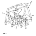
- FIG. 3 A tester developed by the applicant, which is designed according to the prior art described above, is characterized by Fig. 3 exemplified.
- a comparable device for adjusting the weight distribution in an asymmetric three-axle chassis of a locomotive known.
- the chassis is simultaneously loaded with four compressive forces acting from above.
- the load points are each between two axes on both sides of the chassis, wherein each provided on one side of the chassis means for the load entry in the load points of the relevant page are connected to each other via a crossbar.
- this device has a portal-like structure of a considerable size and is not designed for operation at changing locations.
- the object of the invention is to provide a comparison with the prior art more flexible solution for testing bogies of rail vehicles.
- a method should be specified and provide a performance of this method enabling bogie test, which is preferably also suitable as an assembly stand for removal and installation and for setting assemblies of bogies.
- the corresponding test and assembly should also require less space compared to the known from the prior art solutions for bogie test stands.
- a problem solving bogie test bench or test and assembly is characterized by the first device-related claim.
- Advantageous embodiments or further developments of the invention are given by the respective subclaims.
- the loads occurring on a bogie at its intended use on a trained test bench on the still unobstructed bogie be simulated.
- forces are introduced into the bogie, as they are caused in its proper use by the weight of a car body and by other operational loading conditions.
- the effect of these load conditions on the bogie and / or on a track traveled by the bogie is described by measured values obtained by means of transducers of the test bench and computationally processed.
- the forces acting on the simulation of load conditions are not introduced as compressive forces from above into the bogie to be tested.
- the respective force to be introduced for simulating an operating state is applied as a tensile force acting directly on the relevant bogie or on an element of the test bench resting directly on this bogie.
- the wheel contact forces or axle loads acting on the track in each case via the bogie are determined by means of transducers arranged in each case in a measuring device carrier of the correspondingly designed test stand.
- the test method may include determining the respective bogie height at different load conditions.
- the bogie height as known from the prior art, defined as the distance between a mark on the bogie and the top of the rail head of a track. This distance or bogie height can be determined, for example, by means of optical sensors arranged on a correspondingly designed test stand.
- the force acting on the simulation of a load condition can act directly or indirectly on the bogie via an additional element.
- the force acting directly on the bogie thereby engages the respective tensile force from the direction of the track at the top of the rotary pan of a bogie.
- a traction-conveying element is guided through the rotary pan and attached to the top thereof.
- Another variant of the method relates in particular to the testing of bogies which are equipped with air springs or sliders.
- the respective tensile force from the direction of the track attacks centrally on the underside of a yoke, which rests centrally between two axes of the bogie on the air springs or sliders.
- the yoke both a uniform force input on both outer sides of the bogie and an asymmetric load can be simulated.
- a task-solving testing and assembly for bogies of rail vehicles is arranged on a support structure below a bogie to be tested gauges, with means for generating and forwarding to simulate operational stress conditions in the still unobstructed, with his wheels at Aufstandsyaken the gauges positioned bogie forces to be initiated, equipped with transducers for detection by the simulated load conditions on the bogie and / or at the contact points of its wheels caused effects as well as with at least one evaluation unit and with controls.
- the corresponding test and assembly stand is designed such that at least one motor and means for reshaping a torque generated by the motor are arranged in a tensile force acting on the bogie from the direction of the support structure to simulate the loading conditions for the bogie.
- the motor for generating the load conditions simulating forces below the plane of the Aufstandsus the wheels of the bogie is arranged.
- the basic idea of the invention is that in conventional, known test benches above the measuring track, that is above the bogie and its wheel contact points in or on a portal arranged means for generating one of To shift simulation serving compressive force down, preferably to arrange them below the level of Radaufstandspar and to apply with their help the respectively required force as a tensile force.
- the device according to the invention also makes it possible to form such a test and assembly stand mobile. According to an advantageous embodiment of the invention, therefore, apart from the at least one evaluation unit and the controls, all the above elements of the test and assembly stand, including the engine and its torque in the acting on the bogie to be tested tensile force transforming means, therefore, at one Framework arranged.
- Such a frame and the elements arranged thereon for the realization of the test functions form a compact unit which can be loaded without the need for disassembly of elements of the test bench and brought to a place of use.
- the system is basically ready for immediate use.
- the units required for further evaluation of the measured values recorded by the transducers and any control modules for operation can likewise be mounted directly on the compact unit or simply at the place of use via corresponding interfaces provided on the unit, preferably standard interfaces or via a bus system with the remaining electrical or electronic components of the unit are coupled.
- the device in its capacity as a mounting stand, the device also allows assemblies of the bogie, which can be removed or installed or adjusted only under load, conveniently disassemble or assemble or adjust accordingly.
- the rotational movement of the motor shaft is converted by a deflection gear in a translational motion, which is transmitted via a communicating with the reversing gear and standing on the supporting structure of the test and assembly stand bogie drawbar or tension spindle on the bogie.
- the use of at least one traction cable and deflection rollers comes into consideration for the transformation of the rotational movement into a translatory movement. Another possibility is given by the use of at least one operated by the motor hydraulic cylinder.
- the test and assembly stand according to the invention is preferably developed such that the distance of the Ausstands. or the instrument carrier by means of motorized or manually operated spindles according to the respective track and the center distance of a bogie to be tested is adjustable.
- the arranged on the test and assembly stand transducers preferably comprise at least each below the wheels of the bogie to be tested positionable measuring chambers in which shear rods are arranged to detect the wheel wheels acting on a track on the wheels during the intended use of the bogie.
- the measuring device carriers which have already been mentioned several times, with the measuring chambers, which are preferably arranged therein for detecting wheel contact forces, can be used as is the case known in the art, be arranged in or on the rails of a measuring track
- the measuring device carriers are designed as displaceable prism receptacles which can be positioned according to the center distance of a bogie to be tested.
- these prism receptacles are designed as rolling prisms, so that it is possible to drive the wheels of the bogie without changing the location of the bogie.
- the wheels are thereby driven by means of the engine also used for generating the load conditions simulating forces via a corresponding gear or by means of one or more further arranged on the test and assembly stand motors.
- a test stand for bogies of track vehicles is shown, as it is known from the beginning of the description explained prior art.
- the illustration relates to an above-floor variant of such a test stand, which is shown in the drawing without the required roll-in or scissor lift.
- the most essential elements of this test stand are a measuring track 20 with measuring device carriers 2, 3, 4, 5 arranged thereon and a gantry 23 with a loading yoke extending transversely above the measuring track.
- the measuring track 20 and the portal 23 with the load yoke are based on a common substructure.
- the Fig. 1 shows a possible embodiment of the test and assembly stand according to the invention.
- a corresponding forces generating motor 6 is arranged below the plane of the wheel contact points 8, 9, 10, 11 of the bogie 12.
- a corresponding forces generating motor 6 is arranged below the plane of the wheel contact points 8, 9, 10, 11 of the bogie 12.
- a corresponding forces generating motor 6 is arranged below the plane of the wheel contact points 8, 9, 10, 11 of the bogie 12.
- a corresponding forces generating motor 6 is arranged below the plane of the wheel contact points 8, 9, 10, 11 of the bogie 12.
- a corresponding forces generating motor 6 is arranged below the plane of the wheel contact points 8, 9, 10, 11 of the bogie 12.
- a corresponding forces generating motor 6 is arranged below the plane of the wheel contact points 8, 9, 10, 11 of the bogie 12.
- a corresponding forces generating motor 6 is arranged below the plane of
- the wheels 13, 14, 15, 16 of the bogie 12 are positioned on roller prisms, through which measuring device carriers 2, 3, 4, 5 are formed, of which in each case a measuring chamber is received with at least one shear bar arranged therein.
- the transducers in the form of shear rods the wheel contact forces can be determined in a manner known per se, which occur at different load conditions simulated by corresponding tensile forces.
- the measuring device carriers 2, 3, 4, 5 or roller prisms are displaceable or positionable by means of further motors 21, 22 arranged on the stand with respect to the axial distance and the track width of the respective bogie 12 to be tested.
- All essential elements of the test stand namely the measuring transducers 2, 3, 4, 5 arranged in the form of roll prisms, the means for positioning the measuring device carriers 2, 3, 4, 5 and the motor 6 for generating and the pull rod 7
- simulating forces are, as can be seen from the figure, arranged on a compact frame 1.
- the corresponding frame 1 is dimensioned so that the plane of the Radaufstandsan 8, 9, 10, 11 is at the working height of a standing operator.
- the entire arrangement is completed by electrical or electronic units (not shown here) for operation and for computational further processing of the measured variables detected by means of the transducers.
- Corresponding units can but possibly also in the form of a remote control panel over Standard interfaces with the electrical or electronic elements, in particular be connected according to the respectively to be simulated load conditions to be simulated engine 6 and the transducers of the measuring stand. From the figure it can be seen that the test and assembly in this compact form of training can serve as a mobile unit that comparatively easy to load and brought to an audit of bogies 12 to an operator of appropriate track vehicles and on site without much effort practically immediately in operation can be taken.
- the Fig. 2 shows again a detail of the test and assembly stand after the Fig. 1 ,
- the corresponding wheel 13 or an axis 17, 18 of the bogie 12 are driven, so that, for example, the concentricity of the RadARS can be measured or checked.
- Supporting structure for example frame 2, 3, 4, 5 Meters carrier 6 engine 7 Drawbar or spindle 8, 9, 10, 11 contact points 12 bogie 13, 14, 15, 16 wheel 17, 18 axis 19 rotary pan 20 measuring track 21, 22 engine 23 portal
Landscapes
- Physics & Mathematics (AREA)
- General Physics & Mathematics (AREA)
- Investigating Strength Of Materials By Application Of Mechanical Stress (AREA)
- Testing Of Devices, Machine Parts, Or Other Structures Thereof (AREA)
- Force Measurement Appropriate To Specific Purposes (AREA)
Priority Applications (1)
| Application Number | Priority Date | Filing Date | Title |
|---|---|---|---|
| PL10722568T PL2425225T3 (pl) | 2009-04-27 | 2010-04-27 | Sposób kontroli wózków oraz stanowisko kontrolne i stanowisko montażowe |
Applications Claiming Priority (2)
| Application Number | Priority Date | Filing Date | Title |
|---|---|---|---|
| DE102009002678A DE102009002678B4 (de) | 2009-04-27 | 2009-04-27 | Prüfverfahren für Drehgestelle sowie Prüf- und Montagestand |
| PCT/DE2010/050024 WO2010124686A2 (de) | 2009-04-27 | 2010-04-27 | Prüfverfahren für drehgestelle sowie prüf- und montagestand |
Publications (2)
| Publication Number | Publication Date |
|---|---|
| EP2425225A2 EP2425225A2 (de) | 2012-03-07 |
| EP2425225B1 true EP2425225B1 (de) | 2013-05-08 |
Family
ID=42734731
Family Applications (1)
| Application Number | Title | Priority Date | Filing Date |
|---|---|---|---|
| EP10722568.2A Active EP2425225B1 (de) | 2009-04-27 | 2010-04-27 | Prüfverfahren für drehgestelle sowie prüf- und montagestand |
Country Status (10)
| Country | Link |
|---|---|
| US (1) | US8516881B2 (pl) |
| EP (1) | EP2425225B1 (pl) |
| CN (1) | CN102422140B (pl) |
| AU (1) | AU2010243988B2 (pl) |
| CA (1) | CA2759431C (pl) |
| DE (1) | DE102009002678B4 (pl) |
| ES (1) | ES2424247T3 (pl) |
| PL (1) | PL2425225T3 (pl) |
| RU (1) | RU2546913C2 (pl) |
| WO (1) | WO2010124686A2 (pl) |
Families Citing this family (28)
| Publication number | Priority date | Publication date | Assignee | Title |
|---|---|---|---|---|
| DE102011100207B4 (de) * | 2011-05-02 | 2014-08-21 | Schenck Process Gmbh | Verfahren zum Prüfen eines Drehgestells eines Schienenfahrzeugs sowie Prüfstand für ein Drehgestell eines Schienenfahrzeugs |
| CN103175748B (zh) * | 2011-12-20 | 2015-01-21 | 南车青岛四方机车车辆股份有限公司 | 转臂式轴箱静强度及疲劳试验装置及其方法 |
| CN103267648B (zh) * | 2013-05-23 | 2016-03-02 | 西南交通大学 | 铁道车辆转向架蛇行运动实验台 |
| RU2536571C1 (ru) * | 2013-08-09 | 2014-12-27 | Федеральное государственное бюджетное образовательное учреждение высшего профессионального образования "Национальный минерально-сырьевой университет "Горный" | Устройство для оценки ходовых качеств рельсового подвижного состава шахт и рудников |
| CN103454097B (zh) * | 2013-09-18 | 2015-08-12 | 哈尔滨广瀚新能动力有限公司 | 轨道车辆转向架静载综合检测系统 |
| RU2548827C1 (ru) * | 2013-10-31 | 2015-04-20 | Федеральное государственное бюджетное образовательное учреждение высшего профессионального образования "Национальный минерально-сырьевой университет "Горный" | Устройство для определения величины коэффициента сопротивления движению шахтных вагонеток |
| CN103558039B (zh) * | 2013-11-11 | 2016-08-17 | 唐山百川智能机器有限公司 | 动车组转向架尺寸测量调整设备 |
| CZ2015112A3 (cs) * | 2015-02-19 | 2016-07-07 | VĂšKV a.s. | Systém pro měření silových účinků v kontaktu mezi kolem kolejového vozidla a kolejnicí, způsob jeho kalibrace a kalibrační stav |
| CN105136488B (zh) * | 2015-08-05 | 2018-10-02 | 北京新联铁集团股份有限公司 | 一种用于磁悬浮列车转向架检测的试验装置及其检测方法 |
| CN105675316B (zh) * | 2016-04-18 | 2018-04-20 | 中车青岛四方车辆研究所有限公司 | 转向架试验可调式承载系统 |
| CN106556520A (zh) * | 2016-11-25 | 2017-04-05 | 中车青岛四方车辆研究所有限公司 | 转向架性能试验台 |
| DE102016224142A1 (de) * | 2016-12-05 | 2018-06-07 | Zf Friedrichshafen Ag | Modular aufbaubarer Antriebsstrangprüfstand für elektrische Kraftfahrzeugantriebe |
| CN106959216B (zh) * | 2017-05-24 | 2023-07-25 | 襄阳国铁机电股份有限公司 | 一种有轨电车转向架静载试验装置 |
| WO2019195782A1 (en) | 2018-04-05 | 2019-10-10 | Michigan Technological University | On-board propulsion testing apparatus |
| CZ2018202A3 (cs) * | 2018-04-26 | 2019-07-17 | VĂšKV a.s. | Mobilní modul zkušebního stavu pro stacionární zkoušky kolejových vozidel |
| CA3050444A1 (en) * | 2018-07-26 | 2020-01-26 | Secure Energy(Onsite Services) Inc. | Apparatus and method for wheel-assembly and traction-motor change out |
| CN110274780B (zh) * | 2019-08-02 | 2024-04-12 | 吉林大学 | 一种平移式变轨距转向架变轨功能及可靠性试验台 |
| CN110274779B (zh) * | 2019-08-02 | 2024-03-08 | 吉林大学 | 一种新型变轨距转向架变轨功能及可靠性试验台 |
| CN110625355B (zh) * | 2019-10-29 | 2024-08-13 | 通号轨道车辆有限公司 | 一种悬挂式轨道车辆转向架辅助装配装置 |
| WO2021225620A1 (en) | 2020-05-08 | 2021-11-11 | Orbion Space Technology, Inc. | Propulsion system for spacecraft |
| CN112110378A (zh) * | 2020-09-21 | 2020-12-22 | 中车长春轨道客车股份有限公司 | 轴距可调式自定心转向架落成工作台 |
| CN112504705B (zh) * | 2020-11-02 | 2022-05-03 | 中车唐山机车车辆有限公司 | 轨道车辆车体与转向架连接固结强度试验加载装置及方法 |
| WO2022122162A1 (de) * | 2020-12-10 | 2022-06-16 | Nencki Ag | Prüfstand zur prüfung von drehgestellen von schienenfahrzeugen |
| WO2022135711A1 (de) * | 2020-12-23 | 2022-06-30 | Nencki Ag | Prüfstand zur prüfung von drehgestellen von schienenfahrzeugen |
| US20220268651A1 (en) * | 2021-02-22 | 2022-08-25 | Diversified Products, LLC | Dynamometer For Use With Rail Equipment, And Systems And Methods Of Using Same |
| CN112834250B (zh) * | 2021-03-05 | 2022-06-17 | 中浙高铁轴承有限公司 | 一种高铁转向架综合试验台 |
| CN113146508B (zh) * | 2021-04-16 | 2023-09-19 | 中铁第一勘察设计院集团有限公司 | 车体落成转向架移动对位装置 |
| RU2761887C1 (ru) * | 2021-04-23 | 2021-12-13 | Федеральное государственное бюджетное образовательное учреждение высшего образования Иркутский государственный университет путей сообщения (ФГБОУ ВО ИрГУПС) | Стенд для определения динамических нагрузок, возникающих в колесных парах тележки грузового вагона при прохождении кривых участков пути |
Family Cites Families (26)
| Publication number | Priority date | Publication date | Assignee | Title |
|---|---|---|---|---|
| US340883A (en) * | 1886-04-27 | Boss kells | ||
| US2442491A (en) * | 1945-03-05 | 1948-06-01 | Marion W Gieskieng | Railway wheel checking device |
| US2452480A (en) * | 1945-08-17 | 1948-10-26 | James J Mason | Defect detector for railway car wheels |
| US3718040A (en) * | 1971-09-07 | 1973-02-27 | Bessemer And Lake Erie Railway | Method and apparatus for evaluating railroad track structure and car performance |
| US3820016A (en) * | 1972-07-03 | 1974-06-25 | M Gieskieng | Method and apparatus for the detection of cracks and flaws in rail wheels,rails and the like by sliding a prerecorded magnetic medium over the test piece |
| CH566883A5 (pl) * | 1973-07-16 | 1975-09-30 | Matisa Materiel Ind Sa | |
| DE2601259C3 (de) * | 1976-01-15 | 1979-03-29 | Fraunhofer-Gesellschaft Zur Foerderung Der Angewandten Forschung E.V., 8000 Muenchen | Einrichtung zur betriebsähnlichen Prüfung von Radsätzen |
| DE3604186A1 (de) * | 1986-02-10 | 1987-08-13 | Fraunhofer Ges Forschung | Verfahren und einrichtung zur pruefung von schienenfahrzeugraedern unter betriebsaehnlichen belastungsbedingungen |
| CH670228A5 (pl) * | 1986-02-27 | 1989-05-31 | Schweizerische Lokomotiv | |
| US4793047A (en) * | 1986-12-18 | 1988-12-27 | General Electric Company | Method of adjusting the distribution of locomotive axle loads |
| GB2266123A (en) | 1992-04-16 | 1993-10-20 | Keith Ebbrell | Dynamic monitoring apparatus for rail vehicle bearings |
| JPH09325094A (ja) * | 1996-06-05 | 1997-12-16 | Hitachi Ltd | 簡易評価機構 |
| NO992675L (no) * | 1999-06-02 | 2000-12-15 | Frank Chruickshank | Maskinkonsept for vedlikehold av jernbanevogner |
| GB9917203D0 (en) * | 1999-07-23 | 1999-09-22 | Aea Technology Plc | Railway wheel monitoring |
| RU2219514C2 (ru) * | 2002-02-12 | 2003-12-20 | Омский государственный университет путей сообщения | Стенд для технической диагностики рельсовых транспортных средств |
| US6725782B1 (en) * | 2003-03-24 | 2004-04-27 | Franz Plasser Bahnbaumaschinen-Industriegesellschaft M.B.H | Railroad test vehicle comprising a railroad measurement axle suspension |
| US7469479B2 (en) * | 2004-04-21 | 2008-12-30 | J. Müller AG | Method for measuring tracks |
| US20070203621A1 (en) * | 2004-11-23 | 2007-08-30 | Lioyd Haugen | Rail track evaluation system |
| RU50311U1 (ru) * | 2005-06-24 | 2005-12-27 | Морчиладзе Илья Геронтьевич | Стенд для проверки монтажа тележки грузового вагона |
| EP1995145B1 (en) * | 2006-03-13 | 2017-01-11 | Central Japan Railway Company | Carriage lateral movement-limiting system |
| EP1900597B1 (en) * | 2006-09-18 | 2009-08-05 | Bombardier Transportation GmbH | Diagnostic system and method for monitoring a rail system |
| DE102006051725A1 (de) * | 2006-10-30 | 2008-05-08 | Schenck Process Gmbh | Verfahren und Vorrichtung zum Positionieren eines Prüflings in einem Prüfstand für Drehgestelle von Schienenfahrzeugen |
| CN100445721C (zh) * | 2006-12-27 | 2008-12-24 | 西南交通大学 | 轨道车辆转向架参数测定台 |
| DE102007024066B4 (de) * | 2007-05-22 | 2017-06-14 | Knorr-Bremse Systeme für Schienenfahrzeuge GmbH | Drehgestell eines Schienenfahrzeugs mit einer Vorrichtung zur Fehlerüberwachung von Fahrwerkskomponenten |
| US20090095194A1 (en) * | 2007-10-12 | 2009-04-16 | Ajith Kuttannair Kumar | System and method for dynamically affecting a force applied through a rail vehicle axle |
| CN201191234Y (zh) * | 2008-04-23 | 2009-02-04 | 西南交通大学 | 铁路车辆转向架三向刚度测验装置 |
-
2009
- 2009-04-27 DE DE102009002678A patent/DE102009002678B4/de active Active
-
2010
- 2010-04-27 EP EP10722568.2A patent/EP2425225B1/de active Active
- 2010-04-27 US US13/138,935 patent/US8516881B2/en not_active Expired - Fee Related
- 2010-04-27 PL PL10722568T patent/PL2425225T3/pl unknown
- 2010-04-27 WO PCT/DE2010/050024 patent/WO2010124686A2/de not_active Ceased
- 2010-04-27 CA CA2759431A patent/CA2759431C/en not_active Expired - Fee Related
- 2010-04-27 ES ES10722568T patent/ES2424247T3/es active Active
- 2010-04-27 RU RU2011149189/11A patent/RU2546913C2/ru not_active IP Right Cessation
- 2010-04-27 CN CN201080018499.9A patent/CN102422140B/zh not_active Expired - Fee Related
- 2010-04-27 AU AU2010243988A patent/AU2010243988B2/en not_active Ceased
Also Published As
| Publication number | Publication date |
|---|---|
| CA2759431A1 (en) | 2010-11-04 |
| ES2424247T3 (es) | 2013-09-30 |
| US8516881B2 (en) | 2013-08-27 |
| WO2010124686A3 (de) | 2011-01-13 |
| CN102422140B (zh) | 2015-08-12 |
| US20120042720A1 (en) | 2012-02-23 |
| RU2546913C2 (ru) | 2015-04-10 |
| CA2759431C (en) | 2017-07-18 |
| AU2010243988A1 (en) | 2011-12-15 |
| RU2011149189A (ru) | 2013-06-10 |
| PL2425225T3 (pl) | 2013-10-31 |
| WO2010124686A2 (de) | 2010-11-04 |
| DE102009002678A1 (de) | 2010-10-28 |
| DE102009002678B4 (de) | 2012-04-26 |
| AU2010243988B2 (en) | 2017-01-12 |
| EP2425225A2 (de) | 2012-03-07 |
| CN102422140A (zh) | 2012-04-18 |
Similar Documents
| Publication | Publication Date | Title |
|---|---|---|
| EP2425225B1 (de) | Prüfverfahren für drehgestelle sowie prüf- und montagestand | |
| DE112009000488B4 (de) | Testsystem mit Strebenanordnung sowie Verfahren | |
| EP2853878B1 (de) | Kraftfahrzeugprüfsystem | |
| AT512260B1 (de) | Prüfvorrichtung für einen Rollen-Prüfstand | |
| DE102004021488B4 (de) | Prüfstand für Drehgestelle und/oder Radsätze von Schienenfahrzeugen | |
| EP4267932B1 (de) | Radträger zum tragen eines an einem drehgestell angeordneten laufrades und prüfstand zur prüfung von drehgestellen von schienenfahrzeugen | |
| DE102015204020A1 (de) | Mehrfachkonfigurationswindkanalwaage und Verfahren zum Umrüsten der Windkanalwaage | |
| WO2015062772A1 (de) | Mobile fahrzeugprüfanlage | |
| EP3182088B1 (de) | Verfahren zur funktionsprüfung von schwimmplatten als bestandteil eines fahrzeugprüfstandes | |
| EP1484593A2 (de) | Fahrzeugprüfstand | |
| DE10336042C5 (de) | Anordnung und Verfahren zum Prüfen von Rädern eines Schienenfahrzeugs | |
| DE102009024383A1 (de) | Vorrichtung zum Testen von plattenförmigen Werkstücken | |
| EP4290195B1 (de) | Verfahren und system zum kalibrieren einer gleiswaage | |
| EP4331797B1 (de) | Rütteleinrichtung einer betonsteinfertigungsanlage und verfahren zur bestimmung des vertikalen abstands zwischen rütteltisch und prallleisten so einer rütteleinrichtung | |
| AT526356B1 (de) | Prüfvorrichtung mit schwingungsentkoppelter Lagerung | |
| DE102016206420A1 (de) | Tragegestell für einen Bremsenprüfstand | |
| DE102020213971A1 (de) | Rollensatz für kraftfahrzeugprüfstände und prüfstand für kraftfahrzeuge mit einem solchen rollensatz | |
| DE102024112619A1 (de) | Prüfstandsystem für Fahrassistenztechnik und Verfahren | |
| DE202010018168U1 (de) | Anordnung zur automatischen, lagegenauen Ausrichtung eines Kraftfahrzeugs auf einem Prüfstand | |
| DE102011083086A1 (de) | Prüfvorrichtung für Gangways | |
| DE2148107A1 (de) | Hebezeug und messvorrichtung zum bestimmen der statischen unwucht von kraftfahrzeugraedern am fahrzeug | |
| DD250021A3 (de) | Vertikal bewegliche ueberroll- und rollvorrichtung | |
| DE2805798A1 (de) | Gleiswaage |
Legal Events
| Date | Code | Title | Description |
|---|---|---|---|
| PUAI | Public reference made under article 153(3) epc to a published international application that has entered the european phase |
Free format text: ORIGINAL CODE: 0009012 |
|
| 17P | Request for examination filed |
Effective date: 20111122 |
|
| AK | Designated contracting states |
Kind code of ref document: A2 Designated state(s): AT BE BG CH CY CZ DE DK EE ES FI FR GB GR HR HU IE IS IT LI LT LU LV MC MK MT NL NO PL PT RO SE SI SK SM TR |
|
| TPAC | Observations filed by third parties |
Free format text: ORIGINAL CODE: EPIDOSNTIPA |
|
| DAX | Request for extension of the european patent (deleted) | ||
| GRAP | Despatch of communication of intention to grant a patent |
Free format text: ORIGINAL CODE: EPIDOSNIGR1 |
|
| GRAS | Grant fee paid |
Free format text: ORIGINAL CODE: EPIDOSNIGR3 |
|
| GRAA | (expected) grant |
Free format text: ORIGINAL CODE: 0009210 |
|
| RBV | Designated contracting states (corrected) |
Designated state(s): AT BE BG CH CY CZ DK EE ES FI FR GB GR HR HU IE IS IT LI LT LU LV MC MK MT NL NO PL PT RO SE SI SK SM TR |
|
| AK | Designated contracting states |
Kind code of ref document: B1 Designated state(s): AT BE BG CH CY CZ DK EE ES FI FR GB GR HR HU IE IS IT LI LT LU LV MC MK MT NL NO PL PT RO SE SI SK SM TR |
|
| REG | Reference to a national code |
Ref country code: GB Ref legal event code: FG4D Free format text: NOT ENGLISH |
|
| REG | Reference to a national code |
Ref country code: AT Ref legal event code: REF Ref document number: 611307 Country of ref document: AT Kind code of ref document: T Effective date: 20130515 Ref country code: CH Ref legal event code: EP |
|
| REG | Reference to a national code |
Ref country code: IE Ref legal event code: FG4D Free format text: LANGUAGE OF EP DOCUMENT: GERMAN |
|
| REG | Reference to a national code |
Ref country code: DE Ref legal event code: R108 Effective date: 20130502 |
|
| REG | Reference to a national code |
Ref country code: CH Ref legal event code: NV Representative=s name: R. A. EGLI AND CO. PATENTANWAELTE, CH |
|
| REG | Reference to a national code |
Ref country code: ES Ref legal event code: FG2A Ref document number: 2424247 Country of ref document: ES Kind code of ref document: T3 Effective date: 20130930 |
|
| REG | Reference to a national code |
Ref country code: LT Ref legal event code: MG4D |
|
| REG | Reference to a national code |
Ref country code: NL Ref legal event code: VDEP Effective date: 20130508 |
|
| PG25 | Lapsed in a contracting state [announced via postgrant information from national office to epo] |
Ref country code: FI Free format text: LAPSE BECAUSE OF FAILURE TO SUBMIT A TRANSLATION OF THE DESCRIPTION OR TO PAY THE FEE WITHIN THE PRESCRIBED TIME-LIMIT Effective date: 20130508 Ref country code: NO Free format text: LAPSE BECAUSE OF FAILURE TO SUBMIT A TRANSLATION OF THE DESCRIPTION OR TO PAY THE FEE WITHIN THE PRESCRIBED TIME-LIMIT Effective date: 20130808 Ref country code: GR Free format text: LAPSE BECAUSE OF FAILURE TO SUBMIT A TRANSLATION OF THE DESCRIPTION OR TO PAY THE FEE WITHIN THE PRESCRIBED TIME-LIMIT Effective date: 20130809 Ref country code: LT Free format text: LAPSE BECAUSE OF FAILURE TO SUBMIT A TRANSLATION OF THE DESCRIPTION OR TO PAY THE FEE WITHIN THE PRESCRIBED TIME-LIMIT Effective date: 20130508 Ref country code: SI Free format text: LAPSE BECAUSE OF FAILURE TO SUBMIT A TRANSLATION OF THE DESCRIPTION OR TO PAY THE FEE WITHIN THE PRESCRIBED TIME-LIMIT Effective date: 20130508 Ref country code: IS Free format text: LAPSE BECAUSE OF FAILURE TO SUBMIT A TRANSLATION OF THE DESCRIPTION OR TO PAY THE FEE WITHIN THE PRESCRIBED TIME-LIMIT Effective date: 20130908 Ref country code: PT Free format text: LAPSE BECAUSE OF FAILURE TO SUBMIT A TRANSLATION OF THE DESCRIPTION OR TO PAY THE FEE WITHIN THE PRESCRIBED TIME-LIMIT Effective date: 20130909 Ref country code: SE Free format text: LAPSE BECAUSE OF FAILURE TO SUBMIT A TRANSLATION OF THE DESCRIPTION OR TO PAY THE FEE WITHIN THE PRESCRIBED TIME-LIMIT Effective date: 20130508 |
|
| REG | Reference to a national code |
Ref country code: PL Ref legal event code: T3 |
|
| PG25 | Lapsed in a contracting state [announced via postgrant information from national office to epo] |
Ref country code: CY Free format text: LAPSE BECAUSE OF FAILURE TO SUBMIT A TRANSLATION OF THE DESCRIPTION OR TO PAY THE FEE WITHIN THE PRESCRIBED TIME-LIMIT Effective date: 20130508 Ref country code: HR Free format text: LAPSE BECAUSE OF FAILURE TO SUBMIT A TRANSLATION OF THE DESCRIPTION OR TO PAY THE FEE WITHIN THE PRESCRIBED TIME-LIMIT Effective date: 20130508 Ref country code: BG Free format text: LAPSE BECAUSE OF FAILURE TO SUBMIT A TRANSLATION OF THE DESCRIPTION OR TO PAY THE FEE WITHIN THE PRESCRIBED TIME-LIMIT Effective date: 20130808 |
|
| RAP2 | Party data changed (patent owner data changed or rights of a patent transferred) |
Owner name: BASTIAN, RAINER Owner name: STUMVOLL, WOLFGANG |
|
| RIN2 | Information on inventor provided after grant (corrected) |
Inventor name: STUMVOLL, WOLFGANG Inventor name: BASTIAN, RAINER |
|
| PG25 | Lapsed in a contracting state [announced via postgrant information from national office to epo] |
Ref country code: LV Free format text: LAPSE BECAUSE OF FAILURE TO SUBMIT A TRANSLATION OF THE DESCRIPTION OR TO PAY THE FEE WITHIN THE PRESCRIBED TIME-LIMIT Effective date: 20130508 |
|
| PG25 | Lapsed in a contracting state [announced via postgrant information from national office to epo] |
Ref country code: EE Free format text: LAPSE BECAUSE OF FAILURE TO SUBMIT A TRANSLATION OF THE DESCRIPTION OR TO PAY THE FEE WITHIN THE PRESCRIBED TIME-LIMIT Effective date: 20130508 Ref country code: SK Free format text: LAPSE BECAUSE OF FAILURE TO SUBMIT A TRANSLATION OF THE DESCRIPTION OR TO PAY THE FEE WITHIN THE PRESCRIBED TIME-LIMIT Effective date: 20130508 Ref country code: DK Free format text: LAPSE BECAUSE OF FAILURE TO SUBMIT A TRANSLATION OF THE DESCRIPTION OR TO PAY THE FEE WITHIN THE PRESCRIBED TIME-LIMIT Effective date: 20130508 Ref country code: CZ Free format text: LAPSE BECAUSE OF FAILURE TO SUBMIT A TRANSLATION OF THE DESCRIPTION OR TO PAY THE FEE WITHIN THE PRESCRIBED TIME-LIMIT Effective date: 20130508 |
|
| PG25 | Lapsed in a contracting state [announced via postgrant information from national office to epo] |
Ref country code: RO Free format text: LAPSE BECAUSE OF FAILURE TO SUBMIT A TRANSLATION OF THE DESCRIPTION OR TO PAY THE FEE WITHIN THE PRESCRIBED TIME-LIMIT Effective date: 20130508 Ref country code: IT Free format text: LAPSE BECAUSE OF FAILURE TO SUBMIT A TRANSLATION OF THE DESCRIPTION OR TO PAY THE FEE WITHIN THE PRESCRIBED TIME-LIMIT Effective date: 20130508 Ref country code: NL Free format text: LAPSE BECAUSE OF FAILURE TO SUBMIT A TRANSLATION OF THE DESCRIPTION OR TO PAY THE FEE WITHIN THE PRESCRIBED TIME-LIMIT Effective date: 20130508 |
|
| PLBE | No opposition filed within time limit |
Free format text: ORIGINAL CODE: 0009261 |
|
| STAA | Information on the status of an ep patent application or granted ep patent |
Free format text: STATUS: NO OPPOSITION FILED WITHIN TIME LIMIT |
|
| 26N | No opposition filed |
Effective date: 20140211 |
|
| REG | Reference to a national code |
Ref country code: GB Ref legal event code: 732E Free format text: REGISTERED BETWEEN 20140522 AND 20140528 |
|
| REG | Reference to a national code |
Ref country code: CH Ref legal event code: PUEA Owner name: WOLFGANG STUMVOLL, DE Free format text: FORMER OWNER: STUMVOLL, WOLFGANG, DE |
|
| PG25 | Lapsed in a contracting state [announced via postgrant information from national office to epo] |
Ref country code: MC Free format text: LAPSE BECAUSE OF FAILURE TO SUBMIT A TRANSLATION OF THE DESCRIPTION OR TO PAY THE FEE WITHIN THE PRESCRIBED TIME-LIMIT Effective date: 20130508 Ref country code: LU Free format text: LAPSE BECAUSE OF FAILURE TO SUBMIT A TRANSLATION OF THE DESCRIPTION OR TO PAY THE FEE WITHIN THE PRESCRIBED TIME-LIMIT Effective date: 20140427 |
|
| REG | Reference to a national code |
Ref country code: FR Ref legal event code: TQ Owner name: BASTIAN, RAINER, DE Effective date: 20141125 Ref country code: FR Ref legal event code: TQ Owner name: STUMVOLL, WOLFGANG, DE Effective date: 20141125 |
|
| REG | Reference to a national code |
Ref country code: IE Ref legal event code: MM4A |
|
| PG25 | Lapsed in a contracting state [announced via postgrant information from national office to epo] |
Ref country code: IE Free format text: LAPSE BECAUSE OF NON-PAYMENT OF DUE FEES Effective date: 20140427 |
|
| REG | Reference to a national code |
Ref country code: AT Ref legal event code: PC Ref document number: 611307 Country of ref document: AT Kind code of ref document: T Owner name: RAINER BASTIAN, DE Effective date: 20150728 Ref country code: AT Ref legal event code: PC Ref document number: 611307 Country of ref document: AT Kind code of ref document: T Owner name: WOLFGANG STUMVOLL, DE Effective date: 20150728 |
|
| PG25 | Lapsed in a contracting state [announced via postgrant information from national office to epo] |
Ref country code: MT Free format text: LAPSE BECAUSE OF FAILURE TO SUBMIT A TRANSLATION OF THE DESCRIPTION OR TO PAY THE FEE WITHIN THE PRESCRIBED TIME-LIMIT Effective date: 20130508 |
|
| REG | Reference to a national code |
Ref country code: FR Ref legal event code: PLFP Year of fee payment: 7 |
|
| PG25 | Lapsed in a contracting state [announced via postgrant information from national office to epo] |
Ref country code: SM Free format text: LAPSE BECAUSE OF FAILURE TO SUBMIT A TRANSLATION OF THE DESCRIPTION OR TO PAY THE FEE WITHIN THE PRESCRIBED TIME-LIMIT Effective date: 20130508 |
|
| PG25 | Lapsed in a contracting state [announced via postgrant information from national office to epo] |
Ref country code: HU Free format text: LAPSE BECAUSE OF FAILURE TO SUBMIT A TRANSLATION OF THE DESCRIPTION OR TO PAY THE FEE WITHIN THE PRESCRIBED TIME-LIMIT; INVALID AB INITIO Effective date: 20100427 Ref country code: TR Free format text: LAPSE BECAUSE OF FAILURE TO SUBMIT A TRANSLATION OF THE DESCRIPTION OR TO PAY THE FEE WITHIN THE PRESCRIBED TIME-LIMIT Effective date: 20130508 |
|
| REG | Reference to a national code |
Ref country code: FR Ref legal event code: PLFP Year of fee payment: 8 |
|
| PG25 | Lapsed in a contracting state [announced via postgrant information from national office to epo] |
Ref country code: BE Free format text: LAPSE BECAUSE OF NON-PAYMENT OF DUE FEES Effective date: 20140430 |
|
| REG | Reference to a national code |
Ref country code: FR Ref legal event code: PLFP Year of fee payment: 9 |
|
| PG25 | Lapsed in a contracting state [announced via postgrant information from national office to epo] |
Ref country code: MK Free format text: LAPSE BECAUSE OF FAILURE TO SUBMIT A TRANSLATION OF THE DESCRIPTION OR TO PAY THE FEE WITHIN THE PRESCRIBED TIME-LIMIT Effective date: 20130508 |
|
| PGFP | Annual fee paid to national office [announced via postgrant information from national office to epo] |
Ref country code: ES Payment date: 20180523 Year of fee payment: 9 |
|
| PGFP | Annual fee paid to national office [announced via postgrant information from national office to epo] |
Ref country code: PL Payment date: 20180418 Year of fee payment: 9 Ref country code: AT Payment date: 20180418 Year of fee payment: 9 Ref country code: FR Payment date: 20180424 Year of fee payment: 9 |
|
| PGFP | Annual fee paid to national office [announced via postgrant information from national office to epo] |
Ref country code: GB Payment date: 20180424 Year of fee payment: 9 |
|
| REG | Reference to a national code |
Ref country code: AT Ref legal event code: MM01 Ref document number: 611307 Country of ref document: AT Kind code of ref document: T Effective date: 20190427 |
|
| GBPC | Gb: european patent ceased through non-payment of renewal fee |
Effective date: 20190427 |
|
| PG25 | Lapsed in a contracting state [announced via postgrant information from national office to epo] |
Ref country code: GB Free format text: LAPSE BECAUSE OF NON-PAYMENT OF DUE FEES Effective date: 20190427 Ref country code: AT Free format text: LAPSE BECAUSE OF NON-PAYMENT OF DUE FEES Effective date: 20190427 |
|
| PG25 | Lapsed in a contracting state [announced via postgrant information from national office to epo] |
Ref country code: FR Free format text: LAPSE BECAUSE OF NON-PAYMENT OF DUE FEES Effective date: 20190430 |
|
| REG | Reference to a national code |
Ref country code: ES Ref legal event code: FD2A Effective date: 20200901 |
|
| PG25 | Lapsed in a contracting state [announced via postgrant information from national office to epo] |
Ref country code: ES Free format text: LAPSE BECAUSE OF NON-PAYMENT OF DUE FEES Effective date: 20190428 |
|
| PG25 | Lapsed in a contracting state [announced via postgrant information from national office to epo] |
Ref country code: PL Free format text: LAPSE BECAUSE OF NON-PAYMENT OF DUE FEES Effective date: 20190427 |
|
| PGFP | Annual fee paid to national office [announced via postgrant information from national office to epo] |
Ref country code: CH Payment date: 20250423 Year of fee payment: 16 |