EP2421458B1 - Kryochirurgisches instrument - Google Patents
Kryochirurgisches instrument Download PDFInfo
- Publication number
- EP2421458B1 EP2421458B1 EP10713587.3A EP10713587A EP2421458B1 EP 2421458 B1 EP2421458 B1 EP 2421458B1 EP 10713587 A EP10713587 A EP 10713587A EP 2421458 B1 EP2421458 B1 EP 2421458B1
- Authority
- EP
- European Patent Office
- Prior art keywords
- section
- instrument
- tissue gripping
- gripping section
- tissue
- Prior art date
- Legal status (The legal status is an assumption and is not a legal conclusion. Google has not performed a legal analysis and makes no representation as to the accuracy of the status listed.)
- Active
Links
- 239000000463 material Substances 0.000 claims description 18
- 230000002093 peripheral effect Effects 0.000 claims description 15
- 239000012620 biological material Substances 0.000 claims description 13
- 238000001574 biopsy Methods 0.000 claims description 11
- 238000001816 cooling Methods 0.000 claims description 8
- 230000000694 effects Effects 0.000 claims description 7
- 239000004033 plastic Substances 0.000 claims description 6
- 229920003023 plastic Polymers 0.000 claims description 6
- 239000012530 fluid Substances 0.000 claims description 4
- 239000002184 metal Substances 0.000 claims description 3
- 238000010438 heat treatment Methods 0.000 claims description 2
- 238000009413 insulation Methods 0.000 claims description 2
- 239000011148 porous material Substances 0.000 claims description 2
- 210000001519 tissue Anatomy 0.000 description 43
- 239000000523 sample Substances 0.000 description 42
- 210000004072 lung Anatomy 0.000 description 13
- 238000001514 detection method Methods 0.000 description 10
- 210000004224 pleura Anatomy 0.000 description 9
- 125000006850 spacer group Chemical group 0.000 description 9
- 238000007710 freezing Methods 0.000 description 6
- 230000008014 freezing Effects 0.000 description 6
- 239000011248 coating agent Substances 0.000 description 5
- 238000000576 coating method Methods 0.000 description 5
- 238000013461 design Methods 0.000 description 3
- 238000000034 method Methods 0.000 description 3
- 230000008569 process Effects 0.000 description 3
- 239000004020 conductor Substances 0.000 description 2
- 230000007547 defect Effects 0.000 description 2
- 238000012986 modification Methods 0.000 description 2
- 230000004048 modification Effects 0.000 description 2
- 206010006417 Bronchial carcinoma Diseases 0.000 description 1
- 229910000906 Bronze Inorganic materials 0.000 description 1
- 208000029523 Interstitial Lung disease Diseases 0.000 description 1
- 239000004952 Polyamide Substances 0.000 description 1
- 208000027418 Wounds and injury Diseases 0.000 description 1
- 230000009471 action Effects 0.000 description 1
- 230000015572 biosynthetic process Effects 0.000 description 1
- 210000003123 bronchiole Anatomy 0.000 description 1
- 208000003362 bronchogenic carcinoma Diseases 0.000 description 1
- 239000010974 bronze Substances 0.000 description 1
- 238000004891 communication Methods 0.000 description 1
- 239000002826 coolant Substances 0.000 description 1
- KUNSUQLRTQLHQQ-UHFFFAOYSA-N copper tin Chemical compound [Cu].[Sn] KUNSUQLRTQLHQQ-UHFFFAOYSA-N 0.000 description 1
- 230000006378 damage Effects 0.000 description 1
- 230000001419 dependent effect Effects 0.000 description 1
- 238000011161 development Methods 0.000 description 1
- 230000018109 developmental process Effects 0.000 description 1
- 238000002405 diagnostic procedure Methods 0.000 description 1
- 238000005516 engineering process Methods 0.000 description 1
- 238000000605 extraction Methods 0.000 description 1
- 238000002594 fluoroscopy Methods 0.000 description 1
- 230000002757 inflammatory effect Effects 0.000 description 1
- 208000014674 injury Diseases 0.000 description 1
- 230000003902 lesion Effects 0.000 description 1
- 238000004519 manufacturing process Methods 0.000 description 1
- 239000003550 marker Substances 0.000 description 1
- 238000012544 monitoring process Methods 0.000 description 1
- 238000006213 oxygenation reaction Methods 0.000 description 1
- 210000003281 pleural cavity Anatomy 0.000 description 1
- 201000003144 pneumothorax Diseases 0.000 description 1
- 238000005498 polishing Methods 0.000 description 1
- 229920002647 polyamide Polymers 0.000 description 1
- 229920001296 polysiloxane Polymers 0.000 description 1
- 239000004810 polytetrafluoroethylene Substances 0.000 description 1
- 229920001343 polytetrafluoroethylene Polymers 0.000 description 1
- 229920002635 polyurethane Polymers 0.000 description 1
- 239000004814 polyurethane Substances 0.000 description 1
- 210000004879 pulmonary tissue Anatomy 0.000 description 1
- 230000009467 reduction Effects 0.000 description 1
- 210000002345 respiratory system Anatomy 0.000 description 1
- 238000005070 sampling Methods 0.000 description 1
Images


Classifications
-
- A—HUMAN NECESSITIES
- A61—MEDICAL OR VETERINARY SCIENCE; HYGIENE
- A61B—DIAGNOSIS; SURGERY; IDENTIFICATION
- A61B10/00—Other methods or instruments for diagnosis, e.g. instruments for taking a cell sample, for biopsy, for vaccination diagnosis; Sex determination; Ovulation-period determination; Throat striking implements
- A61B10/02—Instruments for taking cell samples or for biopsy
-
- A—HUMAN NECESSITIES
- A61—MEDICAL OR VETERINARY SCIENCE; HYGIENE
- A61B—DIAGNOSIS; SURGERY; IDENTIFICATION
- A61B18/00—Surgical instruments, devices or methods for transferring non-mechanical forms of energy to or from the body
- A61B18/02—Surgical instruments, devices or methods for transferring non-mechanical forms of energy to or from the body by cooling, e.g. cryogenic techniques
-
- A—HUMAN NECESSITIES
- A61—MEDICAL OR VETERINARY SCIENCE; HYGIENE
- A61B—DIAGNOSIS; SURGERY; IDENTIFICATION
- A61B17/00—Surgical instruments, devices or methods, e.g. tourniquets
- A61B2017/00743—Type of operation; Specification of treatment sites
- A61B2017/00809—Lung operations
-
- A—HUMAN NECESSITIES
- A61—MEDICAL OR VETERINARY SCIENCE; HYGIENE
- A61B—DIAGNOSIS; SURGERY; IDENTIFICATION
- A61B17/00—Surgical instruments, devices or methods, e.g. tourniquets
- A61B17/30—Surgical pincettes without pivotal connections
- A61B2017/306—Surgical pincettes without pivotal connections holding by means of suction
-
- A—HUMAN NECESSITIES
- A61—MEDICAL OR VETERINARY SCIENCE; HYGIENE
- A61B—DIAGNOSIS; SURGERY; IDENTIFICATION
- A61B18/00—Surgical instruments, devices or methods for transferring non-mechanical forms of energy to or from the body
- A61B2018/00005—Cooling or heating of the probe or tissue immediately surrounding the probe
- A61B2018/00041—Heating, e.g. defrosting
-
- A—HUMAN NECESSITIES
- A61—MEDICAL OR VETERINARY SCIENCE; HYGIENE
- A61B—DIAGNOSIS; SURGERY; IDENTIFICATION
- A61B18/00—Surgical instruments, devices or methods for transferring non-mechanical forms of energy to or from the body
- A61B2018/00964—Features of probes
-
- A—HUMAN NECESSITIES
- A61—MEDICAL OR VETERINARY SCIENCE; HYGIENE
- A61B—DIAGNOSIS; SURGERY; IDENTIFICATION
- A61B90/00—Instruments, implements or accessories specially adapted for surgery or diagnosis and not covered by any of the groups A61B1/00 - A61B50/00, e.g. for luxation treatment or for protecting wound edges
- A61B90/39—Markers, e.g. radio-opaque or breast lesions markers
Definitions
- the invention relates to a cryosurgical instrument for transbronchial biopsy.
- space-occupying lesions e.g., bronchial carcinoma or peripheral round
- transbronchial biopsy under fluoroscopic control is used as a routine diagnostic method.
- tissue sample from certain areas of the lung further from the central airway.
- C-arm e.g. a fine forceps advanced into the district to be examined so as to be able to specifically remove the tissue samples.
- the instruments When removing tissue in the visible area of the respiratory tract (central airway), the instruments are positioned under endoscopic view. On the other hand, in the case of tissue removal from peripheral lung tissue, the positioning of the instruments is carried out only indirectly under fluoroscopic control. This is associated with a higher complication rate.
- tissue samples biopsy
- the lung pleura pleura visceralis
- the pulmonary tissue causes a defect in the lung skin, air from the lungs flows into the pleural space, resulting in pneumothorax, which results in reduced oxygenation for the patient.
- a cryobiopsy probe is positioned too deep, ie too close to the pleura, the freezing of the tissue to the probe tip (probe head) can also cause the lung skin to freeze.
- a defect of the pleura may result.
- the difficulty lies in the fact that the instruments are very difficult to position during tissue removal from peripheral lung tissue and by experienced users to just before the pleura. In fluoroscopic monitoring, the user has only one 2D image available to control the position of the probe tip. It is therefore difficult to estimate the depth, ie the third dimension.
- the invention has for its object to provide an improved instrument of the type mentioned, which facilitates the examination for the doctor and reduces the risk of complications.
- This object is achieved by a cryosurgical instrument having the features of claim 19 or 10.
- Advantageous developments of the inventive concept are the subject of the dependent claims.
- An essential concept according to a first aspect of the invention is, in addition to a cooled tissue detection section located near the distal end, which is designed so that in the use of the instrument in the cooled state due to cryo-adhesion surrounding biological Material adheres to provide means on the instrument, which prevents adhesion of biological material or tissue immediately at the distal end of the instrument.
- a safety section provided distally of the tissue detection section, which has means for preventing or reducing the adherence of biological material.
- the tissue detection section is indeed arranged directly at the distal end of the instrument, but formed such that on a distal surface, in particular end face, the KryoadPSsions bin compared to the peripheral region is substantially reduced.
- the security section is designed so that it has low thermal conductivity at least in a boundary region to the tissue detection section. It can be provided that the low thermal conductivity is realized by reduced cross-sectional area and / or selection of a poorly heat-conductive material at least in the boundary region. It is understood that the security section can also be formed overall from poorly heat-conducting material or can be embodied with a reduced cross-sectional area with respect to the tissue detection section. As a material come here various plastic materials, with their typically low thermal conductivity, into consideration, and their concrete selection will be made in compliance with the specific requirements of medical technology. Only as an example here silicones, polyurethanes and polyamides may be mentioned.
- the security section has a high heat capacity dimensioned such that, during a short cooling period of the tissue detection section, in particular of less than 5 seconds, its temperature is above a value remains, which adheres to it as a result of cryoadhesive biological material.
- it may be formed of a hard metal, which typically has such a high heat capacity.
- the security portion is made of a material that reduces the cryoadhesion, or in any case is covered with such a material or surrounded by a spacer made of such material.
- a coating or a spacer for realizing this function may consist of a hard material reducing the kryo-adhesion.
- the security section has a, in particular electrical, heating device.
- An embodiment according to the second aspect of the invention is characterized by such a formation of coolants in the tissue detection section that they do not cool only the peripheral portion but the distal end, or thermal insulation is provided between the cooling means and the distal end.
- the peripheral portion, but not the distal end is formed of a material and / or with a geometry and / or structure which promote the adhesion of the biological material.
- the distal surface to which no biological material is to adhere assumes a substantially as low temperature as the tissue detection section, the adherence of biological material to the latter is prevented by the adhesion-promoting coating and / or Promoted adhesion-promoting geometry or surface structure such that the (in this embodiment quite well occurring) adherence of material to the distal end surface of the instrument is less pronounced opposite.
- tissue detection section a plurality of openings is provided, which are in fluid communication with a gas channel in the interior of the instrument body.
- the gas channel is connected in the use of the instrument with a suction device, so that the tissue-detecting portion laterally surrounding material or tissue sucked to this and thereby the KryoadPSsions bin is laterally reinforced.
- This embodiment can also be combined with a targeted adhesion-reducing embodiment of the immediate distal end of the instrument.
- the plurality of openings in the tissue-grasping portion can be realized in a simple and inexpensive manner by manufacturing from a porous material.
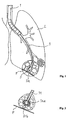
- Fig. 1 shows in a schematic longitudinal sectional view of a lung L with the distal end of an inserted flexible bronchoscope and an imported Kryobiopsiesonde 3.
- a highly flexible guide wire 5 shows the up passed to the pleura P and was bent over by the pleural contact.
- the design of the guide wire 5 with sufficiently low rigidity or high flexibility and from a well-recognized in the applied fluoroscopy control material gives him the function of a marker and allows the managing physician to refrain from further advancement of the instrument when wall contact to the pleura and thus an injury to avoid the pleura.
- FIG. 2 shows the distal end of another cryobiopsy probe 31, which at the distal end of the probe head (tissue detection section) 31a has a spacer (safety portion) 31b which does not freeze upon start-up of a cooling device (not shown) and thus prevents the lung peltus (pleura viseralis) from freezing to the probe tip.
- Fig. 3 shows another Kryobiopsiesonde 32, consisting of a flexible hose 32 'made of plastic; with a probe head (tissue detecting portion) 32a, made of metal, formed so that the probe head and the flexible tube have the same outer diameter.
- a spherical distal end surface 32b of the probe head is here provided with a non-stick coating which reduces the adhesion of surrounding tissue due to the cryo-adhesion effect to the remaining peripheral portion of the probe 32a.
- a non-stick coating which reduces the adhesion of surrounding tissue due to the cryo-adhesion effect to the remaining peripheral portion of the probe 32a. It can be a conventional and proven in medical use non-stick coating, such as PTFE-based, can be used.
- Fig. 4 shows another cryobiopsy probe 33, consisting of a flexible tube 33 ', with a freezer, a probe head 33a and a spacer 33b made of plastic probe tip by its design made of low thermal conductivity plastic material designed so that no tissue during the freezing process to the probe tip ( the spacer) can freeze.
- FIG. 12 shows another cryobiopsy probe 34 consisting of a flexible tube 34 'with a freezer (not shown) in the probe head 34a that projects beyond the flexible tube to better laterally free tissue, the probe tip having a spacer 34b (safety portion); which has poor thermal conductivity and poor thermal contact (small cross section) to the probe head.
- Fig. 6 shows another Kryobiopsiesonde 35, consisting of a flexible hose 35 ', with a freezer 35c in the probe head 35a, which in turn projects beyond the flexible tube to better laterally freeate tissue, the surface geometry being configured to adhere the frozen tissue by positive engagement (in the recesses) and the instrument end having a spacer 35b.
- Fig. 7 shows another cryobiopsy probe 36, consisting of a flexible tube 36 ', with a (not shown) freezer in the probe head 36a and a spacer 36b as a probe tip, the spacer has many small openings, advantageously from sintered bronze, whereby during the freezing process, a gaseous Fluid can escape to prevent tissue from adhering.
- FIG. 8 Figure 3 shows, partially in longitudinal section, another cryobiopsy probe 37, consisting of a flexible tube 37 'with a freezing device (not shown) in the probe head, which projects beyond the flexible tube to better laterally freeate tissue and a stepped safety section 37b, in addition to the Probe head suction openings 37 c are mounted to fix the tissue before the freezing process on the probe head by means of vacuum (negative pressure).
- FIG. 9 Figure 4 shows another cryobiopsy probe 38, consisting of a flexible tube 38 ', with a freezer in the probe head 38a and a thin, highly flexible superelastic probe tip 38b which flips or evades with little resistance, and of a material that is visible under fluoroscopic control, see Fig. 1 ,
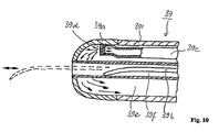
- Fig. 10 3 shows, in longitudinal section, the distal end of another cryobiopsy probe 39, consisting of a flexible tube 39 ', with a freezer in the probe head 39a, one or more gas feeds 39c, one or more expansion orifices 39d, and one or more gas recirculations (FIG. en) 39e for the expanding gas, and with a further channel 39f for introducing a guide wire 39b for positioning and Abstandkzalten to the lung skin (see. Fig. 1 ).
- another cryobiopsy probe 39 consisting of a flexible tube 39 ', with a freezer in the probe head 39a, one or more gas feeds 39c, one or more expansion orifices 39d, and one or more gas recirculations (FIG. en) 39e for the expanding gas, and with a further channel 39f for introducing a guide wire 39b for positioning and Abstandkzalten to the lung skin (see. Fig. 1 ).
Description
- Die Erfindung betrifft ein kryochirurgisches Instrument zur transbronchialen Biopsie. Bei Raumforderungen (z.B. Bronchialkarzinom oder peripherem Rundherd) bzw. entzündlichen, interstitiellen Lungenerkrankungen im peripheren Lungengewebe wird als eine Routinemethode der Diagnostik die transbronchiale Biopsie unter Durchleuchtungskontrolle angewandt. Aufgrund des Durchmessers des flexiblen Bronchoskops ist es oft unmöglich, hiermit eine Gewebeprobe aus bestimmten, weiter von den zentralen Atemwegen entfernen Bereichen der Lunge zu entnehmen. In diesem Fall wird unter Röntgenkontrolle (C-Bogen) z.B. eine feine Zange in den zu untersuchenden Bezirk vorgeschoben, um so gezielt die Gewebeproben entnehmen zu können.
- Flexible Fasszangen bzw. Kryobiopsiesonden zur Durchführung dieser Untersuchung sind bekannt, etwa aus der
EP 0 573 817 A1 . Bei der Gewebeentnahme mit der Kryobiopsie wird die Sondenspitze, d.h. der Sondenkopf, auf das zu behandelnde Gewebe aufgesetzt und ein Gewebebereich, die Gewebeprobe, aufgrund des Kühleffekts (Joule-Thomson-Effekt) am Sondenkopf festgefroren. Das Gewebe bzw. die spätere Gewebeprobe haftet somit an dem gekühlten Sondenkopf und kann durch eine kurze Zugbewegung aus dem umliegenden Gewebe herausgelöst werden, sieheWO 2008/074422 . - Bei der Gewebeentnahme im einsehbaren Bereich der Atemwege (zentrale Atemwege) erfolgt die Positionierung der Instrumente unter endoskopischer Sicht. Dagegen wird bei der Gewebeentnahme aus peripherem Lungengewebe die Positionierung der Instrumente lediglich indirekt unter Durchleuchtungskontrolle durchgeführt. Dies ist mit einer höheren Komplikationsrate verbunden. Bei der Entnahme von Gewebeproben (Biopsie) aus dem peripherem Lungengewebe ist darauf zu achten, dass das Lungengewebe, das mit einer hauchdünnen Hülle, dem Lungenfell (Pleura visceralis) überzogen ist, nicht durch z.B. zu hohe mechanische Kraft, verursacht durch das Instrument bei der Biopsie, durchstossen wird. Entsteht durch die Gewebeentnahme ein Defekt in dem Lungenfell, strömt Luft aus der Lunge in den Pleuraspalt, und es kommt somit zu einem Pneumothorax, der für den Patienten eine reduzierte Sauerstoffversorgung zur Folge hat. Wird andererseits eine Kryobiopsiesonde zu tief, also zu nahe an der Pleura positioniert, kann durch das Anfrieren des Gewebes an die Sondenspitze (Sondenkopf) auch ein Anfrieren des Lungenfells erfolgen. Bei der Extraktion des anhaftenden Gewebes an den Sondenkopf kann so ein Defekt der Pleura entstehen. Die Schwierigkeit liegt darin, dass die Instrumente bei der Gewebeentnahme aus peripherem Lungengewebe nur sehr schwer und von erfahrenen Anwendern bis kurz vor die Pleura positioniert werden können. Bei der Durchleuchtungskontrolle steht dem Anwender nur ein 2D-BiId zur Verfügung, um die Position der Sondenspitze zu kontrollieren. Es ist daher schwierig, auch die Tiefe, also die dritte Dimension, abzuschätzen.
- Der Erfindung liegt die Aufgabe zugrunde, ein verbessertes Instrument der genannten Art anzugeben, das die Untersuchung für den Arzt erleichtert und das Komplikationsrisiko senkt. Diese Aufgabe wird durch ein kryochirurgisches Instrument mit den Merkmalen des Anspruchs 19 oder 10 gelöst. Zweckmäßige Fortbildungen des Erfindungsgedankens sind Gegenstand der abhängigen Ansprüche.
- Ein wesentlicher Gedanke gemäß einem ersten Aspekt der Erfindung besteht darin, zusätzlich zu einem nahe dem distalen Ende angeordneten gekühlten Gewebserfassungsabschnitt, welcher derart ausgebildet ist, dass im Gebrauch des Instruments im gekühlten Zustand aufgrund von Kryoadhäsion umgebendes biologisches Material anhaftet, Mittel am Instrument vorzusehen, mit denen ein Anhaften von biologischem Material bzw. Gewebe unmittelbar am distalen Ende des Instruments verhindert wird. Dies geschieht durch einen distal vom Gewebserfassungsabschnitt vorgesehenen Sicherheitsabschnitt, welcher Mittel zum Verhindern oder Reduzieren des Anhaftens von biologischem Material aufweist. Gemäß einem zweiten, relativ unabhängigen Aspekt der Erfindung ist der Gewebserfassungsabschnitt zwar unmittelbar am distalen Ende des Instruments angeordnet, aber derart ausgebildet, dass an einer distalen Fläche, insbesondere Stirnfläche, der Kryoadhäsionseffekt gegenüber dem Umfangsbereich wesentlich reduziert ist.
- In einer Ausführung gemäß dem ersten Aspekt ist der Sicherheitsabschnitt so gestaltet, dass er mindestens in einem Grenzbereich zum Gewebserfassungsabschnitt niedrige Wärmeleitfähigkeit aufweist. Hierbei kann vorgesehen sein, dass die niedrige Wärmeleitfähigkeit durch reduzierte Querschnittsfläche und/oder Auswahl eines schlecht wärmeleitenden Materials mindestens im Grenzbereich realisiert ist. Es versteht sich, dass der Sicherheitsabschnitt auch insgesamt aus schlecht wärmeleitendem Material gebildet oder mit einer gegenüber dem Gewebserfassungsabschnitt reduzierten Querschnittsfläche ausgeführt sein kann. Als Material kommen hier diverse Kunststoffmaterialien, mit ihrer typischerweise niedrigen Wärmeleitfähigkeit, in Betracht, und deren konkrete Auswahl wird unter Beachtung der speziellen Anforderungen der Medizintechnik erfolgen. Lediglich als Beispiel seien hier Silikone, Polyurethane und Polyamide genannt.
- In einer weiteren Ausführung gemäß dem ersten Aspekt ist vorgesehen, dass der Sicherheitsabschnitt eine derart bemessene hohe Wärmekapazität aufweist, dass während einer kurzen Kühldauer des Gewebserfassungsabschnitts, insbesondere von weniger als 5 Sekunden, seine Temperatur oberhalb eines Werts bleibt, bei dem in Folge Kryoadhäsion biologisches Material an ihm anhaftet. Insbesondere kann er aus einem Hartmetall gebildet sein, welches typischerweise eine solche hohe Wärmekapazität aufweist. Weitere materialseitige Ausführungen erschl ießen sich dem Fachmann angesichts des konstruktiven Aufbaus des Instruments, speziell seiner Kühlung, sowie von Eigenheiten seiner Anwendung, ohne dass es dazu hier konkreterer Hinweise bedürfte.
- Bei einer weiteren Ausführung gemäß dem ersten Aspekt ist der Sicherheitsabschnitt aus einem die Kryoadhäsion reduzierenden Material gefertigt oder jedenfalls mit einem solchen Material bedeckt oder mit einem Abstandhalter aus einem solchen umgeben. Insbesondere kann eine Beschichtung oder ein Abstandshalter zur Realisierung dieser Funktion aus einem die Kryoadhäsion reduzierenden Hartstoff bestehen. In einer weiteren Ausführung gemäß dem ersten Aspekt der Erfindung ist vorgesehen, dass der Sicherheitsabschnitt eine, insbesondere elektrische, Heizeinrichtung aufweist.
- Mehrere der oben genannten Massnahmen können miteinander kombiniert sein. zweiten oder dritten Aspekt der Erfindung sinnvoll kombiniert sein.
- Eine Ausführung gemäß dem zweiten Aspekt der Erfindung zeichnet sich durch eine derartige Ausbildung von Kühlmitteln im Gewebserfassungsabschnitt aus, dass sie nur den Umfangsabschnitt nicht aber das distale Ende kühlen, oder zwischen den Kühlmitteln und dem distalen Ende eine thermische Isolierung vorgesehen ist.
- Hierdurch wird bewirkt, dass die distale Fläche benachbart zum Gewebserfassungsabschnitt eine deutlich höhere Temperatur als der Gewebserfassungsabschnitt selbst (beim Betrieb der Kühleinrichtung) behält, so dass die Temperaturerniedrigung jedenfalls nicht für einen gravierenden Kryoadhäsionseffekt ausreicht.
- In einer Abwandlung dieser Ausführung ist vorgesehen, dass der Umfangsabschnitt, nicht aber das distale Ende, aus einem Material und/oder mit einer Geometrie und/oder Struktur ausgebildet ist, die das Anhaften des biologischen Materials fördern. Hier wird zwar zugelassen, dass die distale Fläche, an der aus den o.a. Gründen kein biologisches Material anhaften soll, eine im Wesentlichen ebenso niedrige Temperatur wie der Gewebserfassungsabschnitt annimmt, das Anhaften von biologischem Material an dem Letzteren wird aber durch die haftungsvermittelnde Beschichtung und/oder haftungsfördernde Geometrie bzw. Oberflächenstruktur derart gefördert, dass das (bei dieser Ausführung durchaus auftretende) Anhaften von Material an der distalen Endfläche des Instruments dem gegenüber weniger ausgeprägt ist. Es versteht sich, dass stattdessen oder in Kombination mit dieser Ausführung auch vorgesehen sein kann, die distale Endfläche mit einer Antihaftbeschichtung zu versehen oder anderweitig (z.B. durch Polieren) so auszubilden, dass die Materialanhaftung dort relativ geringer ist.
- Ein ähnlicher Effekt wird bei einer weiteren Ausführung gemäß dem zweiten Aspekt der Erfindung erreicht, bei der im Gewebserfassungsabschnitt eine Vielzahl von Öffnungen vorgesehen ist, die mit einem Gaskanal im Inneren des Instrumenten-Grundkörpers in Fluidverbindung stehen. Der Gaskanal wird im Gebrauch des Instruments mit einer Ansaugeinrichtung verbunden, so dass den Gewebserfassungsabschnitt lateral umgebendes Material bzw. Gewebe an diesen angesaugt und hierdurch der Kryoadhäsionseffekt lateral verstärkt wird. Auch diese Ausführung kann mit einer gezielt haftungsvermindernden Ausgestaltung des unmittelbaren distalen Endes des Instruments kombiniert sein. Wie auch die weiter oben erwähnte Ausführung des Gewebserfassungsabschnittes mit einer Vielzahl kleiner Öffnungen (die dort eine andere Funktion erfüllt) kann die Vielzahl von Öffnungen im Gewebserfassungsabschnitt in einfacher und kostengünstiger Weise durch die Fertigung aus einem porösen Material realisiert werden.
- Vorteile und Zweckmäßigkeiten der Ausführungsbeispiele ergeben sich im Übrigen aus der nachfolgenden skizzenartigen Beschreibung von Ausführungsbeispielen anhand der Figuren. Von diesen zeigen:
-
Fig. 1 eine schematische Darstellung einer transbronchialen Biopsie mit einem flexiblen Bronchoskop und einem eingeführten Instrument, -
Fig. 2 eine schematische Darstellung einer transbronchialen Biopsie in den Bronchiolen mit einer Kryobiopsiesonde, -
Fig. 3 eine schematische Darstellung einer flexiblen Kryosonde. -
Fig. 4 eine schematische Darstellung einer flexiblen Kryosonde -
Fig. 5 eine schematische Darstellung einer flexiblen Kryosonde, -
Fig. 6 eine schematische Darstellung einer flexiblen Kryosonde, -
Fig. 7 eine schematische Darstellung einer flexiblen Kryosonde, -
Fig. 8 eine schematische Darstellung einer flexiblen Kryosonde, -
Fig. 9 eine schematische Darstellung einer flexiblen Kryosonde, und -
Fig. 10 eine schematische Darstellung einer flexiblen Kryosonde, -
Fig. 1 zeigt in einer schematischen Längsschnittdarstellung einen Lungenflügel L mit dem distalen Ende eines eingeführten flexiblen Bronchoskops l und einer eingeführten Kryobiopsiesonde 3. Wie der vergrößerte Ausschnitt im unteren Bildteil erkennen lässt, steht aus einem distalen Sondenabschnitt 3a des Instruments 3 ein hochflexibler Führungsdraht 5 hervor, der bis an die Pleura P geführt und durch den Pleurakontakt umgebogen wurde. Die Ausführung des Führungsdrahtes 5 mit hinreichend geringer Steifigkeit bzw. hoher Biegsamkeit sowie aus einem im angewandten Durchleuchtungskontrollverfahren gut erkennbaren Material verleiht ihm die Funktion eines Markierungsmittels und erlaubt es dem handhabenden Arzt, bei Wandkontakt zur Pleura ein weiteres Vorschieben des Instruments zu unterlassen und somit eine Verletzung der Pleura zu vermeiden.Fig. 2 zeigt das distale Ende einer weiteren Kryobiopsiesonde 31, die am distalen Ende des Sondenkopfes (Gewebserfassungsabschnittes) 31a einen Abstandshalter (Sicherheitsabschnitt) 31b aufweist, der bei Inbetriebnahme einer (nicht dargestellten) Kühleinrichtung nicht gefriert und so verhindert, dass das Lungenfell P (pleura viseralis) an die Sondenspitze anfriert.Fig. 3 zeigt eine weitere Kryobiopsiesonde 32, bestehend aus einem flexiblen Schlauch 32' aus Kunststoff; mit einem Sondenkopf (Gewebserfassungsabschnitt) 32a, aus Metall, so ausgebildet, dass der Sondenkopf und der flexible Schlauch den gleichen Außendurchmesser aufweisen. Eine sphärische distale Endfläche 32b des Sondenkopfes ist hier mit einer Antihaftbeschichtung versehen, die das Anhaften von umgebendem Gewebe aufgrund des Kryoadhäsionseffektes gegenüber dem verbleibenden Umfangsbereich der Sonde 32a vermindert. Es kann eine herkömmliche und im medizinischen Einsatz bewährte Antihaftbeschichtung, etwa auf PTFE-Basis, verwendet werden. -
Fig. 4 zeigt eine weitere Kryobiopsiesonde 33, bestehend aus einem flexiblen Schlauch 33', mit einer Gefriereinrichtung, einem Sondenkopf 33a und einem Abstandshalter 33b aus Kunststoff als Sondenspitze durch seine Ausführung aus Kunststoffmaterial mit niedriger Wärmeleitfähigkeit so ausgebildet, dass kein Gewebe während des Gefriervorgangs an die Sondenspitze (den Abstandshalter) anfrieren kann. -
Fig. 5 zeigt eine weitere Kryobiopsiesonde 34, bestehend aus einem flexiblen Schlauch 34', mit einer (nicht dargestellten) Gefriereinrichtung im Sondenkopf 34a, die über den flexiblen Schlauch hinaus ragt, um besser Gewebe lateral anzufrieren, wobei der Sondenspitze einen Abstandshalter 34b (Sicherheitsabschnitt) aufweist, der eine schlechte Wärmeleitfähigkeit besitzt und einen schlechten Wärmekontakt (kleinen Querschnitt) zum Sondenkopf aufweist. -
Fig. 6 zeigt eine weitere Kryobiopsiesonde 35, bestehend aus einem flexiblen Schlauch 35', mit einer Gefriereinrichtung 35c im Sondenkopf 35a, die wiederum über den flexiblen Schlauch hinaus ragt, um besser Gewebe lateral anzufrieren, wobei die Oberflächengeometrie so ausgebildet ist, dass das gefrorene Gewebe durch Formschluss (in den Vertiefungen) anhaftet, und wobei das Instrumentenende einen Abstandshalter 35b aufweist.Fig. 7 zeigt eine weitere Kryobiopsiesonde 36, bestehend aus einem flexiblen Schlauch 36', mit einer (nicht dargestellten) Gefriereinrichtung im Sondenkopf 36a und einem Abstandshalter 36b als Sondenspitze, wobei der Abstandshalter viele kleine Öffnungen aufweist, vorteilhaft aus Sinterbronze ist, wodurch während des Gefriervorgangs ein gasförmiges Medium ausströmen kann, um ein Anhaften von Gewebe zu verhindern. -
Fig. 8 zeigt, teilweise im Längsschnitt, eine weitere Kryobiopsiesonde 37, bestehend aus einem flexiblen Schlauch 37' mit einer (nicht dargestellten) Gefriereinrichtung im Sondenkopf, die über den flexiblen Schlauch hinausragt, um besser Gewebe lateral anzufrieren und einem abgestuften Sicherheitsabschnitt 37b, wobei zusätzlich an dem Sondenkopf Absaugöffnungen 37c angebracht sind um das Gewebe vor dem Gefriervorgang an dem Sondenkopf mittels Vakuum (Unterdruck) zu fixieren. -
Fig. 9 zeigt eine weitere Kryobiopsiesonde 38, bestehend aus einem flexiblen Schlauch 38', mit einer Gefriereinrichtung im Sondenkopf 38a und einer dünnen, hochflexiblen superelastischen Sondenspitze 38b, die sich bei geringem Widerstand umlegt oder ausweicht, und aus einem Werkstoff, der unter Durchleuchtungskontrolle sichtbar wird, sieheFig. 1 . -
Fig. 10 zeigt in Längsschnittdarstellung das distale Ende einer weiteren Kryobiopsiesonde 39, bestehend aus einem flexiblen Schlauch 39', mit einer Gefriereinrichtung im Sondenkopf 39a, die eine oder mehrere Gaszuführung(en) 39c, eine oder mehrere Expansionsöffnung(en) 39d und eine oder mehrere Gasrückführung(en) 39e für das expandierende Gas beinhaltet, und mit einem weiteren Kanal 39f zum Einbringen eines Führungsdrahtes 39b zur Positionierung und zum Abstandkzalten zum Lungenfell (vgl.Fig. 1 ). - Die Ausführung der Erfindung ist nicht auf die oben skizzenhaft beschriebenen Beispiele und hervorgehobenen Aspekte beschränkt, sondern ebenso in einer Vielzahl von Abwandlungen möglich, die im Rahmen fachgemäßen Handelns liegen.
Claims (10)
- Kryochirurgisches Instrument zur transbronchialen Biopsie, mit einem langgestreckten Instrumenten-Grundkörper mit einem distalen und einem proximalen Ende, bezogen auf die Gebrauchslage, einem nahe dem distalen Ende angeordneten gekühlten Gewebserfassungsabschnitt, welcher derart ausgebildet ist, dass im Gebrauch des Instruments im gekühlten Zustand aufgrund von Kryoadhäsion umgebendes biologisches Material anhaftet gekennzeichnet durch einen distal vorn Gewebserfassungsabschnitt vorgesehenen Sicherheitsabschnitt, welcher Mittel zum Verhindern oder Reduzieren des Anhaftens von biologischem Material aufweist.
- Instrument nach Anspruch 1, wobei der Sicherheitsabschnitt mindestens in einem Grenzbereich zum Gewebserfassungsabschnitt niedrige Wärmeleitfähigkeit aufweist und dazu aus einem Kunststoffmaterial besteht.
- Instrument nach Anspruch 2, wobei die niedrige Wärmeleitfähigkeit durch reduzierte Querschnittsfläche und/oder Auswahl eines Kunststoffmaterials mindestens im Grenzbereich realisiert ist.
- Instrument nach einem der vorangehenden Ansprüche, wobei der Sicherheitsabschnitt eine derart bemessene hohe Wärmekapazität aufweist, dass während einer kurzen Kühldauer des Gewebserfassungsabschnitts, insbesondere von weniger als 5 Sekunden, seine Temperatur oberhalb eines Werts bleibt, bei dem aufgrund von Kryoadhäsion biologisches Material an ihm anhaftet, wobei der Sicherheitsabschnitt dazu aus einem Hartmetall gebildet ist.
- Instrument nach einem der vorangehenden Ansprüche, wobei der Sicherheitsabschnitt aus einem die Kryoadhäsion gegenüber dem Umfangsbereich reduzierenden Material besteht oder mit einem solchen bedeckt ist.
- Instrument nach Anspruch 5, wobei der Sicherheitsabschnitt aus einem die Kryoadhäsion gegenüber dem Umfangsbereich reduzierenden Hartstoff beschichtet ist.
- Instrument nach einem der vorangehenden Ansprüche, wobei der Sicherheitsabschnitt eine, insbesondere elektrische, Heizeinrichtung aufweist.
- Instrument nach einem der vorangehenden Ansprüche, wobei über die Oberfläche des Sicherheitsabschnitts eine Vielzahl von Öffnungen verteilt ist, die mit einem Gaskanal im Inneren des InstrumentenGrundkörpers in Fluidveribindung stehen.
- Kryochirurgisches Instrument zur transbronchialen Biopsie, mit einem langgestreckten Instrumenten-Grundkörper mit einem distalen und einem proximalen Ende, bezogen auf die Gebrauchslage, einem am oder nahe dem distalen Ende angeordneten gekühlten Gewebserfassungsabschnitt, welcher derart ausgebildet ist, dass im Gebrauch des Instruments im gekühlten Zustand aufgrund von Kryoadhäsion umgebendes biologisches Material anhaftet, gekennzeichnet dadurch, dass der Gewebserfassungsabschnitt derart ausgebildet ist, dass der Kryoadhäsionseffekt an einer distalen Fläche, insbesondere Stirnfläche, des Instruments gegenüber dem Umfang sabschnitt des Gewebserfassungsabschnitts wesentlich reduziert ist, wobei dazu Kühlmittel im Gewebserfassungsabschnitt derart ausgebildet sind, dass sie nur den Umfangsabschnitt, nicht aber die distale Fläche kühlen, oder zwischen den Kühlmitteln und der distalen Fläche eine thermische Isolierung vorgesehen ist.
- Kryochirurgisches Instrument zur transbronchialen Biopsie, mit einem langgestreckten Instrumenten-Grundkörper mit einem distalen und einem proximalen Ende, bezogen auf die Gebrauchslage, einem am oder nahe dem distalen Ende angeordneten gekühlten Gewebserfassungsabschnitt, welcher derart ausgebildet ist, dass im Gebrauch des Instruments im gekühlten Zustand aufgrund von Kryoadhäsion umgebendes biologisches Material anhaftet, gekennzeichnet dadurch, dass der Gewebserfassungsabschnitt derart ausgebildet ist, dass der Kryoadhäsionseffekt an einer distalen Fläche, insbesondere Stirnfläche, des Instruments gegenüber dem Umfang sabschnitt des Gewebserfassungsabschnitts wesentlich reduziert ist, wobei der Umfangsabschnitt, nicht aber die distale Fläche mit einer Geometrie und/oder Struktur ausgebildet ist, die das Anhaften des biologischen Materials fördert,
indem im Gewebserfassungsabschnitt eine Vielzahl von Öffnungen vorgesehen ist, die mit einem Gaskanal im Inneren des Instrumenten-Grundkörpers in Fluidverbindung stehen, oder
indem der Sicherheitsabschnitt und/oder der Gewebserfassungsabschnitt aus porösem Material besteht, durch dessen Porosität die Vielzahl von Öffnungen realisiert ist.
Priority Applications (1)
| Application Number | Priority Date | Filing Date | Title |
|---|---|---|---|
| PL10713587T PL2421458T3 (pl) | 2009-04-21 | 2010-04-14 | Narzędzie kriochirurgiczne |
Applications Claiming Priority (2)
| Application Number | Priority Date | Filing Date | Title |
|---|---|---|---|
| DE102009018291A DE102009018291A1 (de) | 2009-04-21 | 2009-04-21 | Kryochirurgisches Instrument |
| PCT/EP2010/002291 WO2010121738A1 (de) | 2009-04-21 | 2010-04-14 | Kryochirurgisches instrument |
Publications (2)
| Publication Number | Publication Date |
|---|---|
| EP2421458A1 EP2421458A1 (de) | 2012-02-29 |
| EP2421458B1 true EP2421458B1 (de) | 2013-07-10 |
Family
ID=42224650
Family Applications (1)
| Application Number | Title | Priority Date | Filing Date |
|---|---|---|---|
| EP10713587.3A Active EP2421458B1 (de) | 2009-04-21 | 2010-04-14 | Kryochirurgisches instrument |
Country Status (7)
| Country | Link |
|---|---|
| US (2) | US20120071868A1 (de) |
| EP (1) | EP2421458B1 (de) |
| JP (1) | JP5567659B2 (de) |
| CN (1) | CN102481166B (de) |
| DE (1) | DE102009018291A1 (de) |
| PL (1) | PL2421458T3 (de) |
| WO (2) | WO2010121739A1 (de) |
Families Citing this family (11)
| Publication number | Priority date | Publication date | Assignee | Title |
|---|---|---|---|---|
| WO2010019481A1 (en) | 2008-08-11 | 2010-02-18 | Conceptx Medical, Inc. | Systems and methods for treating dyspnea, including via electrical afferent signal blocking |
| WO2013163322A1 (en) | 2012-04-24 | 2013-10-31 | Cibiem, Inc. | Endovascular catheters and methods for carotid body ablation |
| IL219477A0 (en) | 2012-04-30 | 2012-07-31 | Berger Thermal Res Ltd | A method for coupling between catheter tip and tissue by icing their interface and apparatus therefor |
| WO2013181667A1 (en) | 2012-06-01 | 2013-12-05 | Cibiem, Inc. | Percutaneous methods and devices for carotid body ablation |
| EP2854680A4 (de) | 2012-06-01 | 2016-07-20 | Cibiem Inc | Verfahren und vorrichtungen für kryogene halsschlagader-körperablation |
| EP3957262A1 (de) * | 2013-12-18 | 2022-02-23 | Novoxel Ltd. | Vorrichtungen für gewebevaporisation |
| WO2015138795A1 (en) | 2014-03-12 | 2015-09-17 | Cibiem, Inc. | Carotid body ablation with a transvenous ultrasound imaging and ablation catheter |
| CA2968644A1 (en) | 2014-12-19 | 2016-06-23 | Toufic AZAR | Surgical method and system for performing the same |
| JP6518784B2 (ja) * | 2015-03-26 | 2019-05-22 | スパイレーション インコーポレイテッド ディー ビー エイ オリンパス レスピラトリー アメリカ | サンプリング装置の遠位端部において局所的真空を生成する装置 |
| EP3323366B1 (de) | 2016-11-18 | 2020-09-30 | Erbe Elektromedizin GmbH | Kryosonde und verfahren zur herstellung einer solchen |
| CA3135707A1 (en) * | 2019-04-10 | 2020-10-15 | ArktiKus LLC | Cooling and refrigeration based on vacuum-driven water evaporation |
Family Cites Families (32)
| Publication number | Priority date | Publication date | Assignee | Title |
|---|---|---|---|---|
| US3298371A (en) * | 1965-02-11 | 1967-01-17 | Arnold S J Lee | Freezing probe for the treatment of tissue, especially in neurosurgery |
| US3536075A (en) * | 1967-08-01 | 1970-10-27 | Univ Northwestern | Cryosurgical instrument |
| US3749100A (en) * | 1968-08-13 | 1973-07-31 | Bio Controls Corp | Suppository electrode structure |
| DE3300677C2 (de) * | 1983-01-11 | 1986-12-18 | O.D.A.M. - Office de Distribution d'Appareils Médicaux, Wissembourg | Applikator zum Zuführen und/oder Abführen von Hochfrequenzenergie |
| CA1313482C (en) * | 1988-04-11 | 1993-02-09 | Judith Shevach Tufel | Hemorrhoid inflammation reducing device |
| GB2226497B (en) * | 1988-12-01 | 1992-07-01 | Spembly Medical Ltd | Cryosurgical probe |
| JP2646906B2 (ja) | 1991-09-20 | 1997-08-27 | 株式会社日立製作所 | 情報処理装置用携帯ケース |
| JPH0576415U (ja) * | 1992-03-19 | 1993-10-19 | 南雄 河野 | 前立腺肥大症凍結手術用プローベ |
| US5281215A (en) * | 1992-04-16 | 1994-01-25 | Implemed, Inc. | Cryogenic catheter |
| US5238002A (en) | 1992-06-08 | 1993-08-24 | C. R. Bard, Inc. | Disposable biopsy forceps |
| EP0646359B1 (de) * | 1993-10-05 | 2000-06-14 | S.L.T. Japan Co., Ltd. | Laser Ballon-Katheter |
| US5549600A (en) * | 1994-07-01 | 1996-08-27 | Cynosure, Inc. | Surgical laser probe with thermal cutting |
| US7220257B1 (en) * | 2000-07-25 | 2007-05-22 | Scimed Life Systems, Inc. | Cryotreatment device and method |
| US5906612A (en) * | 1997-09-19 | 1999-05-25 | Chinn; Douglas O. | Cryosurgical probe having insulating and heated sheaths |
| US5895403A (en) * | 1997-10-17 | 1999-04-20 | Collinsworth; Lonnie Rae | Surgical cutting tool |
| WO2000047121A2 (de) * | 1999-02-12 | 2000-08-17 | Nikolai Korpan | Vorrichtung für kryochirurgische eingriffe, insbesondere für die tumorbehandlung |
| EP1216002A4 (de) | 1999-05-25 | 2003-02-12 | Douglas O Chinn | Kryosonde mit isolierendem und beheiztem mantel |
| US6770070B1 (en) * | 2000-03-17 | 2004-08-03 | Rita Medical Systems, Inc. | Lung treatment apparatus and method |
| US6540694B1 (en) * | 2000-10-16 | 2003-04-01 | Sanarus Medical, Inc. | Device for biopsy tumors |
| CN1319683C (zh) | 2002-07-11 | 2007-06-06 | 联合工程公司 | 用于有助于从铸件上除去砂模的方法和装置 |
| US20040024392A1 (en) | 2002-08-05 | 2004-02-05 | Lewis James D. | Apparatus and method for cryosurgery |
| IL151486A0 (en) * | 2002-08-26 | 2003-04-10 | Levin Alexander | Cryosurgical instrument and its accessory system |
| US20050267529A1 (en) * | 2004-05-13 | 2005-12-01 | Heber Crockett | Devices, systems and methods for tissue repair |
| EA200700344A1 (ru) * | 2004-07-20 | 2007-08-31 | Серджинетикс, Инк. | Многоэлектродный электрохирургический инструмент |
| US8348855B2 (en) * | 2005-08-29 | 2013-01-08 | Galil Medical Ltd. | Multiple sensor device for measuring tissue temperature during thermal treatment |
| JP2009524469A (ja) * | 2006-01-26 | 2009-07-02 | ガリル メディカル リミテッド | 複数の冷凍プローブの調和された挿入のための装置及び方法 |
| CA2659261C (en) * | 2006-07-28 | 2017-03-07 | Centre Hospitalier Universitaire De Quebec | Probe, sleeve, system, method and kit for performing percutaneous thermotherapy |
| US7909227B2 (en) * | 2006-12-19 | 2011-03-22 | Endocare, Inc. | Cryosurgical probe with vacuum insulation tube assembly |
| DE102007020582A1 (de) * | 2006-12-19 | 2008-06-26 | Erbe Elektromedizin Gmbh | Kryochirurgisches Instrument und Verfahren zum Abtrennen einer Gewebeprobe von umliegendem Gewebe eines zu behandelnden biologischen Gewebes |
| WO2008156353A1 (en) * | 2007-06-18 | 2008-12-24 | Wittens Cornelis Hendrikus Ann | Cryo probe, method for shaping a cryo probe |
| US20100324546A1 (en) * | 2007-07-09 | 2010-12-23 | Alexander Levin | Cryosheath |
| DE102009049683B4 (de) * | 2009-10-19 | 2016-06-09 | Richard Wolf Gmbh | Endoskopisches Instrument |
-
2009
- 2009-04-21 DE DE102009018291A patent/DE102009018291A1/de not_active Withdrawn
-
2010
- 2010-04-14 US US13/265,789 patent/US20120071868A1/en not_active Abandoned
- 2010-04-14 EP EP10713587.3A patent/EP2421458B1/de active Active
- 2010-04-14 PL PL10713587T patent/PL2421458T3/pl unknown
- 2010-04-14 WO PCT/EP2010/002292 patent/WO2010121739A1/de active Application Filing
- 2010-04-14 WO PCT/EP2010/002291 patent/WO2010121738A1/de active Application Filing
- 2010-04-14 JP JP2012506373A patent/JP5567659B2/ja not_active Expired - Fee Related
- 2010-04-14 CN CN201080027449.7A patent/CN102481166B/zh not_active Expired - Fee Related
-
2017
- 2017-06-30 US US15/638,649 patent/US11229476B2/en active Active
Also Published As
| Publication number | Publication date |
|---|---|
| WO2010121738A1 (de) | 2010-10-28 |
| JP5567659B2 (ja) | 2014-08-06 |
| US20170360416A1 (en) | 2017-12-21 |
| DE102009018291A1 (de) | 2010-10-28 |
| WO2010121739A1 (de) | 2010-10-28 |
| CN102481166B (zh) | 2015-01-28 |
| CN102481166A (zh) | 2012-05-30 |
| JP2012523936A (ja) | 2012-10-11 |
| EP2421458A1 (de) | 2012-02-29 |
| PL2421458T3 (pl) | 2013-10-31 |
| US11229476B2 (en) | 2022-01-25 |
| US20120071868A1 (en) | 2012-03-22 |
Similar Documents
| Publication | Publication Date | Title |
|---|---|---|
| EP2421458B1 (de) | Kryochirurgisches instrument | |
| DE102013203335B4 (de) | Lungenbiopsienadel | |
| US9326754B2 (en) | Method and apparatus for tissue sampling | |
| DE60021300T2 (de) | Geschlitzter Drainagekatheter mit Stylet | |
| DE60318595T2 (de) | Biopsievorrichtungen | |
| DE102008024946B4 (de) | Kryochirurgisches Instrument zur Gewinnung einer Gewebeprobe | |
| CN104519806B (zh) | 内窥镜活体取样器械、内窥镜、及获取活检样本的方法 | |
| DE69433302T2 (de) | Vorrichtung zur mehrfachen probenentnahme | |
| EP2114276B1 (de) | Kryochirurgisches instrument zum abtrennen einer gewebeprobe von umliegendem gewebe eines zu behandelnden biologischen gewebes | |
| US11096678B2 (en) | Systems and methods for eccentric nodule tissue acquisition | |
| DE69432434T2 (de) | Katheter mit unperforierter schutzbarriere | |
| DE112016000756T5 (de) | Vorrichtung zum Erzeugen eines lokalen Vakuums an einem distalen Ende einer Probennahmevorrichtunng | |
| US20180116645A1 (en) | Stylet and Needle Combinations Used to Collect Tissue Samples During Endoscopic Procedures | |
| EP1575430B1 (de) | Optisches biopsieinstrument | |
| DE69433382T2 (de) | Vorrichtung zur wiederholten probenentnahme mittels beweglicher probenröhrchen | |
| AT514209B1 (de) | Vorrichtung zur Probennahme | |
| WO2008116563A1 (de) | Instrument für die medizinische untersuchung von engen körperkanälen | |
| EP3656332A1 (de) | Handstück zur handhabung einer lichtleiterfaser bei einem laserchirurgischen eingriff | |
| EP0943292A1 (de) | Spiralsonde | |
| DE112016005402T5 (de) | Hülsen zur nadeleinführung | |
| DE102008061063A1 (de) | Kryosonde, Kryochirurgisches Gerät | |
| DE102019105198A1 (de) | Katheteranordnung mit versatzvorrichtung zur gewebeprobenahme | |
| DE3732582A1 (de) | Aspirationskanuele zur gewebeprobeentnahme aus der gebaermutterhoehle | |
| DE102015114538A1 (de) | Mehrlumenkatheter zur Durchführung endoskopischer Interventionen | |
| AT409454B (de) | Kryomammotom |
Legal Events
| Date | Code | Title | Description |
|---|---|---|---|
| PUAI | Public reference made under article 153(3) epc to a published international application that has entered the european phase |
Free format text: ORIGINAL CODE: 0009012 |
|
| 17P | Request for examination filed |
Effective date: 20111021 |
|
| AK | Designated contracting states |
Kind code of ref document: A1 Designated state(s): AT BE BG CH CY CZ DE DK EE ES FI FR GB GR HR HU IE IS IT LI LT LU LV MC MK MT NL NO PL PT RO SE SI SK SM TR |
|
| DAX | Request for extension of the european patent (deleted) | ||
| 17Q | First examination report despatched |
Effective date: 20120920 |
|
| GRAP | Despatch of communication of intention to grant a patent |
Free format text: ORIGINAL CODE: EPIDOSNIGR1 |
|
| INTG | Intention to grant announced |
Effective date: 20130327 |
|
| GRAS | Grant fee paid |
Free format text: ORIGINAL CODE: EPIDOSNIGR3 |
|
| GRAA | (expected) grant |
Free format text: ORIGINAL CODE: 0009210 |
|
| AK | Designated contracting states |
Kind code of ref document: B1 Designated state(s): AT BE BG CH CY CZ DE DK EE ES FI FR GB GR HR HU IE IS IT LI LT LU LV MC MK MT NL NO PL PT RO SE SI SK SM TR |
|
| REG | Reference to a national code |
Ref country code: GB Ref legal event code: FG4D Free format text: NOT ENGLISH |
|
| REG | Reference to a national code |
Ref country code: CH Ref legal event code: EP Ref country code: AT Ref legal event code: REF Ref document number: 620482 Country of ref document: AT Kind code of ref document: T Effective date: 20130715 |
|
| REG | Reference to a national code |
Ref country code: IE Ref legal event code: FG4D Free format text: LANGUAGE OF EP DOCUMENT: GERMAN |
|
| REG | Reference to a national code |
Ref country code: DE Ref legal event code: R096 Ref document number: 502010003960 Country of ref document: DE Effective date: 20130905 |
|
| PG25 | Lapsed in a contracting state [announced via postgrant information from national office to epo] |
Ref country code: SI Free format text: LAPSE BECAUSE OF FAILURE TO SUBMIT A TRANSLATION OF THE DESCRIPTION OR TO PAY THE FEE WITHIN THE PRESCRIBED TIME-LIMIT Effective date: 20130710 |
|
| REG | Reference to a national code |
Ref country code: PL Ref legal event code: T3 |
|
| REG | Reference to a national code |
Ref country code: NL Ref legal event code: VDEP Effective date: 20130710 |
|
| REG | Reference to a national code |
Ref country code: LT Ref legal event code: MG4D |
|
| PG25 | Lapsed in a contracting state [announced via postgrant information from national office to epo] |
Ref country code: PT Free format text: LAPSE BECAUSE OF FAILURE TO SUBMIT A TRANSLATION OF THE DESCRIPTION OR TO PAY THE FEE WITHIN THE PRESCRIBED TIME-LIMIT Effective date: 20131111 Ref country code: IS Free format text: LAPSE BECAUSE OF FAILURE TO SUBMIT A TRANSLATION OF THE DESCRIPTION OR TO PAY THE FEE WITHIN THE PRESCRIBED TIME-LIMIT Effective date: 20131110 Ref country code: HR Free format text: LAPSE BECAUSE OF FAILURE TO SUBMIT A TRANSLATION OF THE DESCRIPTION OR TO PAY THE FEE WITHIN THE PRESCRIBED TIME-LIMIT Effective date: 20130710 Ref country code: CY Free format text: LAPSE BECAUSE OF FAILURE TO SUBMIT A TRANSLATION OF THE DESCRIPTION OR TO PAY THE FEE WITHIN THE PRESCRIBED TIME-LIMIT Effective date: 20130814 Ref country code: LT Free format text: LAPSE BECAUSE OF FAILURE TO SUBMIT A TRANSLATION OF THE DESCRIPTION OR TO PAY THE FEE WITHIN THE PRESCRIBED TIME-LIMIT Effective date: 20130710 Ref country code: SE Free format text: LAPSE BECAUSE OF FAILURE TO SUBMIT A TRANSLATION OF THE DESCRIPTION OR TO PAY THE FEE WITHIN THE PRESCRIBED TIME-LIMIT Effective date: 20130710 Ref country code: NO Free format text: LAPSE BECAUSE OF FAILURE TO SUBMIT A TRANSLATION OF THE DESCRIPTION OR TO PAY THE FEE WITHIN THE PRESCRIBED TIME-LIMIT Effective date: 20131010 |
|
| PG25 | Lapsed in a contracting state [announced via postgrant information from national office to epo] |
Ref country code: FI Free format text: LAPSE BECAUSE OF FAILURE TO SUBMIT A TRANSLATION OF THE DESCRIPTION OR TO PAY THE FEE WITHIN THE PRESCRIBED TIME-LIMIT Effective date: 20130710 Ref country code: ES Free format text: LAPSE BECAUSE OF FAILURE TO SUBMIT A TRANSLATION OF THE DESCRIPTION OR TO PAY THE FEE WITHIN THE PRESCRIBED TIME-LIMIT Effective date: 20131021 Ref country code: GR Free format text: LAPSE BECAUSE OF FAILURE TO SUBMIT A TRANSLATION OF THE DESCRIPTION OR TO PAY THE FEE WITHIN THE PRESCRIBED TIME-LIMIT Effective date: 20131011 Ref country code: LV Free format text: LAPSE BECAUSE OF FAILURE TO SUBMIT A TRANSLATION OF THE DESCRIPTION OR TO PAY THE FEE WITHIN THE PRESCRIBED TIME-LIMIT Effective date: 20130710 Ref country code: NL Free format text: LAPSE BECAUSE OF FAILURE TO SUBMIT A TRANSLATION OF THE DESCRIPTION OR TO PAY THE FEE WITHIN THE PRESCRIBED TIME-LIMIT Effective date: 20130710 |
|
| PG25 | Lapsed in a contracting state [announced via postgrant information from national office to epo] |
Ref country code: CY Free format text: LAPSE BECAUSE OF FAILURE TO SUBMIT A TRANSLATION OF THE DESCRIPTION OR TO PAY THE FEE WITHIN THE PRESCRIBED TIME-LIMIT Effective date: 20130710 |
|
| PG25 | Lapsed in a contracting state [announced via postgrant information from national office to epo] |
Ref country code: RO Free format text: LAPSE BECAUSE OF FAILURE TO SUBMIT A TRANSLATION OF THE DESCRIPTION OR TO PAY THE FEE WITHIN THE PRESCRIBED TIME-LIMIT Effective date: 20130710 Ref country code: SK Free format text: LAPSE BECAUSE OF FAILURE TO SUBMIT A TRANSLATION OF THE DESCRIPTION OR TO PAY THE FEE WITHIN THE PRESCRIBED TIME-LIMIT Effective date: 20130710 Ref country code: EE Free format text: LAPSE BECAUSE OF FAILURE TO SUBMIT A TRANSLATION OF THE DESCRIPTION OR TO PAY THE FEE WITHIN THE PRESCRIBED TIME-LIMIT Effective date: 20130710 Ref country code: DK Free format text: LAPSE BECAUSE OF FAILURE TO SUBMIT A TRANSLATION OF THE DESCRIPTION OR TO PAY THE FEE WITHIN THE PRESCRIBED TIME-LIMIT Effective date: 20130710 Ref country code: CZ Free format text: LAPSE BECAUSE OF FAILURE TO SUBMIT A TRANSLATION OF THE DESCRIPTION OR TO PAY THE FEE WITHIN THE PRESCRIBED TIME-LIMIT Effective date: 20130710 |
|
| PLBE | No opposition filed within time limit |
Free format text: ORIGINAL CODE: 0009261 |
|
| STAA | Information on the status of an ep patent application or granted ep patent |
Free format text: STATUS: NO OPPOSITION FILED WITHIN TIME LIMIT |
|
| 26N | No opposition filed |
Effective date: 20140411 |
|
| REG | Reference to a national code |
Ref country code: DE Ref legal event code: R097 Ref document number: 502010003960 Country of ref document: DE Effective date: 20140411 |
|
| PG25 | Lapsed in a contracting state [announced via postgrant information from national office to epo] |
Ref country code: LU Free format text: LAPSE BECAUSE OF FAILURE TO SUBMIT A TRANSLATION OF THE DESCRIPTION OR TO PAY THE FEE WITHIN THE PRESCRIBED TIME-LIMIT Effective date: 20140414 Ref country code: MC Free format text: LAPSE BECAUSE OF FAILURE TO SUBMIT A TRANSLATION OF THE DESCRIPTION OR TO PAY THE FEE WITHIN THE PRESCRIBED TIME-LIMIT Effective date: 20130710 |
|
| REG | Reference to a national code |
Ref country code: CH Ref legal event code: PL |
|
| REG | Reference to a national code |
Ref country code: IE Ref legal event code: MM4A |
|
| PG25 | Lapsed in a contracting state [announced via postgrant information from national office to epo] |
Ref country code: LI Free format text: LAPSE BECAUSE OF NON-PAYMENT OF DUE FEES Effective date: 20140430 Ref country code: CH Free format text: LAPSE BECAUSE OF NON-PAYMENT OF DUE FEES Effective date: 20140430 |
|
| PG25 | Lapsed in a contracting state [announced via postgrant information from national office to epo] |
Ref country code: IE Free format text: LAPSE BECAUSE OF NON-PAYMENT OF DUE FEES Effective date: 20140414 |
|
| PG25 | Lapsed in a contracting state [announced via postgrant information from national office to epo] |
Ref country code: MT Free format text: LAPSE BECAUSE OF FAILURE TO SUBMIT A TRANSLATION OF THE DESCRIPTION OR TO PAY THE FEE WITHIN THE PRESCRIBED TIME-LIMIT Effective date: 20130710 |
|
| REG | Reference to a national code |
Ref country code: FR Ref legal event code: PLFP Year of fee payment: 7 |
|
| PG25 | Lapsed in a contracting state [announced via postgrant information from national office to epo] |
Ref country code: SM Free format text: LAPSE BECAUSE OF FAILURE TO SUBMIT A TRANSLATION OF THE DESCRIPTION OR TO PAY THE FEE WITHIN THE PRESCRIBED TIME-LIMIT Effective date: 20130710 |
|
| REG | Reference to a national code |
Ref country code: AT Ref legal event code: MM01 Ref document number: 620482 Country of ref document: AT Kind code of ref document: T Effective date: 20150414 |
|
| PG25 | Lapsed in a contracting state [announced via postgrant information from national office to epo] |
Ref country code: BG Free format text: LAPSE BECAUSE OF FAILURE TO SUBMIT A TRANSLATION OF THE DESCRIPTION OR TO PAY THE FEE WITHIN THE PRESCRIBED TIME-LIMIT Effective date: 20130710 |
|
| PG25 | Lapsed in a contracting state [announced via postgrant information from national office to epo] |
Ref country code: HU Free format text: LAPSE BECAUSE OF FAILURE TO SUBMIT A TRANSLATION OF THE DESCRIPTION OR TO PAY THE FEE WITHIN THE PRESCRIBED TIME-LIMIT; INVALID AB INITIO Effective date: 20100414 Ref country code: TR Free format text: LAPSE BECAUSE OF FAILURE TO SUBMIT A TRANSLATION OF THE DESCRIPTION OR TO PAY THE FEE WITHIN THE PRESCRIBED TIME-LIMIT Effective date: 20130710 Ref country code: BE Free format text: LAPSE BECAUSE OF FAILURE TO SUBMIT A TRANSLATION OF THE DESCRIPTION OR TO PAY THE FEE WITHIN THE PRESCRIBED TIME-LIMIT Effective date: 20140430 |
|
| PG25 | Lapsed in a contracting state [announced via postgrant information from national office to epo] |
Ref country code: AT Free format text: LAPSE BECAUSE OF NON-PAYMENT OF DUE FEES Effective date: 20150414 |
|
| REG | Reference to a national code |
Ref country code: FR Ref legal event code: PLFP Year of fee payment: 8 |
|
| REG | Reference to a national code |
Ref country code: FR Ref legal event code: PLFP Year of fee payment: 9 |
|
| PG25 | Lapsed in a contracting state [announced via postgrant information from national office to epo] |
Ref country code: MK Free format text: LAPSE BECAUSE OF FAILURE TO SUBMIT A TRANSLATION OF THE DESCRIPTION OR TO PAY THE FEE WITHIN THE PRESCRIBED TIME-LIMIT Effective date: 20130710 |
|
| PGFP | Annual fee paid to national office [announced via postgrant information from national office to epo] |
Ref country code: IT Payment date: 20220421 Year of fee payment: 13 Ref country code: GB Payment date: 20220419 Year of fee payment: 13 Ref country code: FR Payment date: 20220427 Year of fee payment: 13 Ref country code: DE Payment date: 20220527 Year of fee payment: 13 |
|
| PGFP | Annual fee paid to national office [announced via postgrant information from national office to epo] |
Ref country code: PL Payment date: 20220318 Year of fee payment: 13 |
|
| REG | Reference to a national code |
Ref country code: DE Ref legal event code: R119 Ref document number: 502010003960 Country of ref document: DE |
|
| GBPC | Gb: european patent ceased through non-payment of renewal fee |
Effective date: 20230414 |
|
| PG25 | Lapsed in a contracting state [announced via postgrant information from national office to epo] |
Ref country code: GB Free format text: LAPSE BECAUSE OF NON-PAYMENT OF DUE FEES Effective date: 20230414 |
|
| PG25 | Lapsed in a contracting state [announced via postgrant information from national office to epo] |
Ref country code: GB Free format text: LAPSE BECAUSE OF NON-PAYMENT OF DUE FEES Effective date: 20230414 Ref country code: FR Free format text: LAPSE BECAUSE OF NON-PAYMENT OF DUE FEES Effective date: 20230430 Ref country code: DE Free format text: LAPSE BECAUSE OF NON-PAYMENT OF DUE FEES Effective date: 20231103 |