US11229476B2 - Cryosurgical instrument - Google Patents
Cryosurgical instrument Download PDFInfo
- Publication number
- US11229476B2 US11229476B2 US15/638,649 US201715638649A US11229476B2 US 11229476 B2 US11229476 B2 US 11229476B2 US 201715638649 A US201715638649 A US 201715638649A US 11229476 B2 US11229476 B2 US 11229476B2
- Authority
- US
- United States
- Prior art keywords
- section
- instrument
- safety
- cryosurgical instrument
- cross
- Prior art date
- Legal status (The legal status is an assumption and is not a legal conclusion. Google has not performed a legal analysis and makes no representation as to the accuracy of the status listed.)
- Active
Links
Images


Classifications
-
- A—HUMAN NECESSITIES
- A61—MEDICAL OR VETERINARY SCIENCE; HYGIENE
- A61B—DIAGNOSIS; SURGERY; IDENTIFICATION
- A61B18/00—Surgical instruments, devices or methods for transferring non-mechanical forms of energy to or from the body
- A61B18/02—Surgical instruments, devices or methods for transferring non-mechanical forms of energy to or from the body by cooling, e.g. cryogenic techniques
-
- A—HUMAN NECESSITIES
- A61—MEDICAL OR VETERINARY SCIENCE; HYGIENE
- A61B—DIAGNOSIS; SURGERY; IDENTIFICATION
- A61B10/00—Other methods or instruments for diagnosis, e.g. instruments for taking a cell sample, for biopsy, for vaccination diagnosis; Sex determination; Ovulation-period determination; Throat striking implements
- A61B10/02—Instruments for taking cell samples or for biopsy
-
- A—HUMAN NECESSITIES
- A61—MEDICAL OR VETERINARY SCIENCE; HYGIENE
- A61B—DIAGNOSIS; SURGERY; IDENTIFICATION
- A61B17/00—Surgical instruments, devices or methods, e.g. tourniquets
- A61B2017/00743—Type of operation; Specification of treatment sites
- A61B2017/00809—Lung operations
-
- A—HUMAN NECESSITIES
- A61—MEDICAL OR VETERINARY SCIENCE; HYGIENE
- A61B—DIAGNOSIS; SURGERY; IDENTIFICATION
- A61B17/00—Surgical instruments, devices or methods, e.g. tourniquets
- A61B17/30—Surgical pincettes without pivotal connections
- A61B2017/306—Surgical pincettes without pivotal connections holding by means of suction
-
- A—HUMAN NECESSITIES
- A61—MEDICAL OR VETERINARY SCIENCE; HYGIENE
- A61B—DIAGNOSIS; SURGERY; IDENTIFICATION
- A61B18/00—Surgical instruments, devices or methods for transferring non-mechanical forms of energy to or from the body
- A61B2018/00005—Cooling or heating of the probe or tissue immediately surrounding the probe
- A61B2018/00041—Heating, e.g. defrosting
-
- A—HUMAN NECESSITIES
- A61—MEDICAL OR VETERINARY SCIENCE; HYGIENE
- A61B—DIAGNOSIS; SURGERY; IDENTIFICATION
- A61B18/00—Surgical instruments, devices or methods for transferring non-mechanical forms of energy to or from the body
- A61B2018/00964—Features of probes
-
- A—HUMAN NECESSITIES
- A61—MEDICAL OR VETERINARY SCIENCE; HYGIENE
- A61B—DIAGNOSIS; SURGERY; IDENTIFICATION
- A61B90/00—Instruments, implements or accessories specially adapted for surgery or diagnosis and not covered by any of the groups A61B1/00 - A61B50/00, e.g. for luxation treatment or for protecting wound edges
- A61B90/39—Markers, e.g. radio-opaque or breast lesions markers
Definitions
- Embodiments of the invention relate to a cryosurgical instrument, in particular a biopsy instrument for transbronchial biopsy.
- the transbronchial biopsy under fluoroscopic control is performed as a routine diagnostic procedure of masses (e.g., bronchial carcinoma or a peripheral round lesion) and/or inflammatory interstitial pulmonary disease in the peripheral tissue of the lungs. Due to the diameter of the flexible bronchoscope, it is frequently impossible to remove a tissue sample from certain pulmonary regions that are remote from the central respiratory tract. In this case, fine forceps are advanced under fluoroscopic control (C-arm) to the region to be examined to be able to remove tissue samples in a targeted manner.
- C-arm fluoroscopic control
- cryobiopsy probes for performing this procedure have been known, for example, from European publication EP 0 573 817 A1.
- the probe tip i.e., the probe head
- a tissue region the tissue sample
- the tissue, or the later tissue sample adheres to the cooled probe head and can be detached from the surrounding tissue by a short pulling motion; see WO 2008/074422.
- the instruments When tissue is removed from the visualizable region of the respiratory tract (central respiratory tract), the instruments are positioned under endoscopic visualization. Contrary to this procedure, when tissue is removed from the peripheral pulmonary tissue, the instruments are positioned only indirectly under fluoroscopic control. This is associated with a higher rate of complications.
- tissue samples are taken (biopsy) from the peripheral pulmonary tissue
- care must be taken so that the pulmonary tissue that is covered with an extremely thin sheath, the pleura ( Pleura visceralis ), is not punctured by the instrument used for the biopsy, e.g., by too great a mechanical force.
- any damage is caused to the pleura as a result of the tissue removal, air flows out of the lung and into the pleural cavity and results in a pneumothorax that results in a reduced oxygen supply for the patient.
- a cryobiopsy probe is positioned too deeply, i.e., too close to the pleura, it is possible that the pleura will also freeze to the probe tip when freezing the tissue to the probe tip (probe head). Damage to the pleura may occur when the tissue adhering to the probe head is extracted.
- An object of the embodiments of the invention is to provide an improved instrument of the above-mentioned type, said instrument facilitating the examination by the physician and lowering the risk of complications.
- tissue grasping section located near the distal end, said tissue grasping section being designed such that, when the instrument is being used in a cooled state, surrounding biological material will adhere due to cryoadhesion.
- a safety section provided distally from the tissue grasping section, said safety section comprising means for preventing or reducing the adhesion of biological material.
- the tissue grasping section is indeed directly arranged on the distal end of the instrument; however, it is designed such that the cryoadhesion effect on a distal surface, in particular the end surface, is substantially reduced compared to that of the peripheral region.
- the safety section is designed such that it exhibits low thermal conductivity—at least in a border region of the tissue grasping section.
- the low thermal conductivity can be accomplished by a reduced cross-sectional surface and/or by the selection of a material that is a poor thermal conductor—at least in the border region.
- the entire safety section may consist of a material that is a poor thermal conductor or be designed with a cross-sectional area that is reduced compared to that of the tissue grasping section.
- Appropriate materials are, in particular, diverse plastic materials displaying their typically low thermal conductivity, and their specific selection will take into consideration the special requirements of medical technology. Mentioned here, as examples only, are silicones, polyurethanes and polyamides.
- the safety section exhibits a thermal capacity that is dimensioned such that the temperature of said safety section remains above a value at which biological material will adhere to said safety section during a short cooling duration of the tissue grasping section, in particular a duration of less than 5 seconds.
- said safety section may be made of a hard metal that, typically, exhibits such a high thermal capacity. Additional embodiments relating to the materials are obvious to the person skilled in the art, namely, considering the design of the instrument, specifically its cooling, and also considering the particularities of its use.
- the safety section is made of a material that reduces cryoadhesion or, at any rate, is covered by such a material, or is enclosed by a spacer of such a material.
- a coating or spacer may, in particular, consist of a hard substance that reduces cryoadhesion.
- the safety section comprises a heating device, in particular an electric heating device.
- a plurality of openings that are in fluid communication with a gas channel inside the instrument base body are distributed over the surface of the safety section.
- the gas channel is connected to a pressure generating device that supplies a pressurized fluid (e.g., gas), said fluid being disposed to exit through the many small openings.
- a pressurized fluid e.g., gas
- One embodiment in accordance with the second aspect is characterized in that cooling agents are provided in the tissue grasping section such that they only cool the peripheral section, but not the distal surface, or in that a thermal insulation can be provided between the cooling agents and the distal surface.
- a modification of this embodiment provides that the peripheral section, but not the distal surface, be made of a material and/or have a geometric configuration and/or structure that promote the adhesion of the biological material. Indeed, in this case it is permissible that the distal surface, where no biological material is to adhere for the aforementioned reasons, assumes an essentially equally low temperature as the tissue grasping section; however, the adhesion of biological material to the latter is promoted by the adhesion-conveying coating and/or adhesion-promoting geometric configuration or surface structure such that the adhesion of material (that certainly occurs in this embodiment) is less pronounced on the distal end surface of the instrument compared therewith.
- distal end surface with an anti-adhesive coating or to finish it in another way (e.g., by polishing) such that the adhesion of the material is relatively lower in that location.
- tissue grasping section is provided with a plurality of openings that are in fluid communication with a gas channel on the inside the instrument base body.
- the gas channel is connected with an aspirating device, so that material or tissue laterally surrounding the tissue grasping section is aspirated and, as a result of this, the cryoadhesion effect is laterally intensified.
- This embodiment can also be combined with a targeted adhesion-reducing embodiment of the immediate distal end of the instrument.
- the plurality of openings in the tissue grasping section can be implemented in a simple and cost-effective manner by using a porous material for fabrication.
- FIG. 1 is a schematic representation of a transbronchial biopsy with a flexible bronchoscope and an inserted instrument
- FIG. 2 is a schematic representation of a transbronchial biopsy in the bronchioli with a cryobiopsy probe
- FIG. 3 is a schematic representation of a flexible cryoprobe in accordance with an embodiment of the invention.
- FIG. 4 is a schematic representation of a flexible cryoprobe in accordance with an embodiment of the invention.
- FIG. 5 is a schematic representation of a flexible cryoprobe in accordance with an embodiment of the invention.
- FIG. 6 is a schematic representation of a flexible cryoprobe in accordance with an embodiment of the invention.
- FIG. 7 is a schematic representation of a flexible cryoprobe in accordance with an embodiment of the invention.
- FIG. 8 is a schematic representation of a flexible cryoprobe in accordance with an embodiment of the invention.
- FIG. 9 is a schematic representation of a flexible cryoprobe in accordance with an embodiment of the invention.
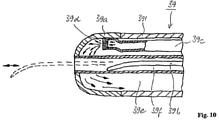
- FIG. 10 is a schematic representation of a flexible cryoprobe in accordance with an embodiment of the invention.
- FIG. 1 shows a schematic representation of the longitudinal section of a lung L, with the distal end of an inserted flexible bronchoscope 1 and an inserted cryobiopsy probe 3 .
- a highly flexible guidewire 5 projects from a distal probe section 3 a of the instrument 3 , said guidewire 5 having been guided up to the pleura P and having been bent over due to contact with the pleura P.
- said guidewire 5 has the function of a marker means and allows the physician handling it to stop any additional advancement of the instrument upon contact with the pleura wall, avoiding any injury to the pleura.
- FIG. 2 shows the distal end of another cryobiopsy probe 31 comprising a spacer (safety section) 31 b on the distal end of the probe head (tissue grasping section) 31 a , which spacer will not freeze when a cooling device (not shown) is activated, preventing the pleura P ( Pleura visceralis ) from freezing to the probe tip.
- a spacer safety section
- pleura P Pleura visceralis
- FIG. 3 shows another cryobiopsy probe 32 comprising a flexible tube 32 ′ of plastic material, a probe head (tissue grasping section) 32 a of metal designed such that the probe head and the flexible tube have the same outside diameter.
- a spherical distal end surface 32 b of the probe head is provided with an anti-adhesive coating that minimizes the adhesion of surrounding tissue caused by the cryoadhesion effect, compared with the remaining peripheral region of the probe 32 a .
- a conventional anti-adhesive coating for example, on a PTFE basis—proven in medical applications can be used.
- FIG. 4 shows another cryobiopsy probe 33 comprising a flexible tube 33 ′, a freezing device, a probe head 33 a and a spacer 33 b of plastic material as the probe tip, said spacer being made of plastic material exhibiting low thermal conductivity such that no tissue can freeze to the probe tip (spacer) during the freezing process.
- FIG. 5 shows another cryobiopsy probe 34 comprising a flexible tube 34 ′, a freezing device (not illustrated) in the probe head 34 a , said freezing device projecting beyond the flexible tube to better freeze tissue in a lateral direction; in which case, the probe tip comprises a spacer 34 b (safety section) that is a poor thermal conductor and exhibits poor thermal contact (small cross-section) with the probe head.
- a spacer 34 b safety section
- FIG. 6 shows another cryobiopsy probe 35 comprising a flexible tube 35 ′, a freezing device 35 c in the probe head 35 a , said freezing device again projecting beyond the flexible tube to better freeze tissue in a lateral direction; in which case, the geometric configuration of the surface is such that the frozen tissue adheres due to a positive connection (in the recesses), and in which case the instrument end comprises a spacer 35 b.
- FIG. 7 shows another cryobiopsy probe 36 comprising a flexible tube 36 ′, a freezing device (not illustrated) in the probe head 36 a , and a spacer 36 b as the probe head; in which case, the spacer has many small openings and is preferably made of sintered bronze, as a result of which a gaseous medium can flow out during the freezing process to prevent any adhesion of tissue.
- FIG. 8 shows, partially in longitudinal section, another cryobiopsy probe 37 comprising a flexible tube 37 ′, a freezing device (not illustrated) in the probe head, said freezing device projecting beyond the flexible tube to better freeze tissue in a lateral direction, and comprising a stepped safety section 37 b , in which additional aspiration openings 37 c are provided on the probe head to fixate the tissue by vacuum (negative pressure) to the probe head prior to the freezing process.
- FIG. 9 shows another cryobiopsy probe 38 comprising a flexible tube 38 ′, a freezing device in the probe head 38 a , and a thin, highly flexible, super-elastic probe tip 38 b that will bend or yield with minimal resistance and that consists of a material that will be visible under fluoroscopic control (see FIG. 1 ).
- FIG. 10 shows a representation of a longitudinal section of the distal end of another cryobiopsy probe 39 comprising a flexible tube 39 ′, a freezing device in the probe head 39 a that contains one or more gas supply lines 39 c , one or more expansion openings 39 d and one or more gas return lines 39 e for the expanding gas, and that contains an additional channel 39 f for introducing a guidewire 39 b for positioning and maintaining a distance from the pleura (see FIG. 1 ).
Abstract
Description
Claims (20)
Applications Claiming Priority (3)
| Application Number | Priority Date | Filing Date | Title |
|---|---|---|---|
| DE102009018291A DE102009018291A1 (en) | 2009-04-21 | 2009-04-21 | Cryosurgical instrument |
| DE102009018291.8 | 2009-04-21 | ||
| PCT/EP2010/002291 WO2010121738A1 (en) | 2009-04-21 | 2010-04-14 | Cryosurgical instrument |
Related Parent Applications (2)
| Application Number | Title | Priority Date | Filing Date |
|---|---|---|---|
| PCT/EP2010/002291 Continuation WO2010121738A1 (en) | 2009-04-21 | 2010-04-14 | Cryosurgical instrument |
| US13/265,789 Continuation US20120071868A1 (en) | 2009-04-21 | 2010-04-14 | Cryosurgical instrument |
Publications (2)
| Publication Number | Publication Date |
|---|---|
| US20170360416A1 US20170360416A1 (en) | 2017-12-21 |
| US11229476B2 true US11229476B2 (en) | 2022-01-25 |
Family
ID=42224650
Family Applications (2)
| Application Number | Title | Priority Date | Filing Date |
|---|---|---|---|
| US13/265,789 Abandoned US20120071868A1 (en) | 2009-04-21 | 2010-04-14 | Cryosurgical instrument |
| US15/638,649 Active US11229476B2 (en) | 2009-04-21 | 2017-06-30 | Cryosurgical instrument |
Family Applications Before (1)
| Application Number | Title | Priority Date | Filing Date |
|---|---|---|---|
| US13/265,789 Abandoned US20120071868A1 (en) | 2009-04-21 | 2010-04-14 | Cryosurgical instrument |
Country Status (7)
| Country | Link |
|---|---|
| US (2) | US20120071868A1 (en) |
| EP (1) | EP2421458B1 (en) |
| JP (1) | JP5567659B2 (en) |
| CN (1) | CN102481166B (en) |
| DE (1) | DE102009018291A1 (en) |
| PL (1) | PL2421458T3 (en) |
| WO (2) | WO2010121738A1 (en) |
Families Citing this family (11)
| Publication number | Priority date | Publication date | Assignee | Title |
|---|---|---|---|---|
| US9089700B2 (en) | 2008-08-11 | 2015-07-28 | Cibiem, Inc. | Systems and methods for treating dyspnea, including via electrical afferent signal blocking |
| DE112013002175T5 (en) | 2012-04-24 | 2015-01-22 | Cibiem, Inc. | Endovascular catheters and procedures for ablation of the carotid body |
| IL219477A0 (en) | 2012-04-30 | 2012-07-31 | Berger Thermal Res Ltd | A method for coupling between catheter tip and tissue by icing their interface and apparatus therefor |
| US9398930B2 (en) | 2012-06-01 | 2016-07-26 | Cibiem, Inc. | Percutaneous methods and devices for carotid body ablation |
| WO2013181660A1 (en) | 2012-06-01 | 2013-12-05 | Cibiem, Inc. | Methods and devices for cryogenic carotid body ablation |
| EP3957262A1 (en) * | 2013-12-18 | 2022-02-23 | Novoxel Ltd. | Devices for tissue vaporization |
| WO2015138795A1 (en) | 2014-03-12 | 2015-09-17 | Cibiem, Inc. | Carotid body ablation with a transvenous ultrasound imaging and ablation catheter |
| WO2016098082A1 (en) | 2014-12-19 | 2016-06-23 | Azar Toufic | Surgical method and system for performing the same |
| CN107427291B (en) | 2015-03-26 | 2020-09-15 | 捷锐士股份有限公司 | Device for generating a partial vacuum at the distal end of a sampling device |
| EP3323366B1 (en) | 2016-11-18 | 2020-09-30 | Erbe Elektromedizin GmbH | Cryoprobe and method for producing same |
| WO2020208604A1 (en) * | 2019-04-10 | 2020-10-15 | ArktiKus LLC | Cooling and refrigeration based on vacuum-driven water evaporation |
Citations (29)
| Publication number | Priority date | Publication date | Assignee | Title |
|---|---|---|---|---|
| US3298371A (en) * | 1965-02-11 | 1967-01-17 | Arnold S J Lee | Freezing probe for the treatment of tissue, especially in neurosurgery |
| US3536075A (en) * | 1967-08-01 | 1970-10-27 | Univ Northwestern | Cryosurgical instrument |
| US3749100A (en) * | 1968-08-13 | 1973-07-31 | Bio Controls Corp | Suppository electrode structure |
| US4605012A (en) * | 1983-01-11 | 1986-08-12 | Odam, Societe Anonyme | Applicator for supplying radio-frequency energy to and from an object |
| US4938221A (en) * | 1988-04-11 | 1990-07-03 | Tuffel Judith S | Hemorrhoid inflammation reducing device |
| US5078713A (en) * | 1988-12-01 | 1992-01-07 | Spembly Medical Limited | Cryosurgical probe |
| JPH0576415A (en) | 1991-09-20 | 1993-03-30 | Hitachi Ltd | Portable case for information processor or the like |
| EP0573817A1 (en) | 1992-06-08 | 1993-12-15 | C.R. Bard, Inc. | Disposable biopsy forceps |
| US5281215A (en) * | 1992-04-16 | 1994-01-25 | Implemed, Inc. | Cryogenic catheter |
| US5549600A (en) * | 1994-07-01 | 1996-08-27 | Cynosure, Inc. | Surgical laser probe with thermal cutting |
| US5895403A (en) | 1997-10-17 | 1999-04-20 | Collinsworth; Lonnie Rae | Surgical cutting tool |
| CA2371776A1 (en) | 1999-05-25 | 2000-11-30 | Douglas O. Chinn | Cryosurgical probe having insulating and heated sheaths |
| US6224590B1 (en) * | 1993-10-05 | 2001-05-01 | S.L.T. Japan Co., Ltd. | Laser balloon catheter |
| US20020045842A1 (en) | 2000-10-16 | 2002-04-18 | Van Bladel Kevin H. | Device for biopsy of tumors |
| JP2003535615A (en) | 1999-02-12 | 2003-12-02 | コルパン,ニコライ | Cryosurgical devices, especially for the treatment of tumors |
| WO2004007121A1 (en) | 2002-07-11 | 2004-01-22 | Consolidated Engineering Company, Inc. | Method and apparatus for assisting removal of sand moldings from castings |
| US20040024392A1 (en) | 2002-08-05 | 2004-02-05 | Lewis James D. | Apparatus and method for cryosurgery |
| US6770070B1 (en) * | 2000-03-17 | 2004-08-03 | Rita Medical Systems, Inc. | Lung treatment apparatus and method |
| US20050267529A1 (en) | 2004-05-13 | 2005-12-01 | Heber Crockett | Devices, systems and methods for tissue repair |
| US20060025757A1 (en) * | 2004-07-20 | 2006-02-02 | Heim Warren P | Multielectrode electrosurgical instrument |
| WO2007026354A1 (en) | 2005-08-29 | 2007-03-08 | Galil Medical Ltd. | Multiple sensor device for measuring tissue temperature during thermal treatment |
| WO2007086056A2 (en) | 2006-01-26 | 2007-08-02 | Galil Medical Ltd. | Device for coordinated insertion of a plurality of cryoprobes |
| US20070250050A1 (en) * | 2000-07-25 | 2007-10-25 | Scimed Life Systems, Inc. A Minnesota Corporation | Cryotreatment device and method |
| WO2008011730A1 (en) | 2006-07-28 | 2008-01-31 | Centre Hospitalier Universitaire Du Quebec | Probe, sleeve, system, method and kit for performing percutaneous thermotherapy |
| WO2008074422A1 (en) | 2006-12-19 | 2008-06-26 | Erbe Elektromedizin Gmbh | Cryosurgical instrument for separating a tissue sample from surrounding tissue of a biological tissue that is to be treated |
| WO2008079696A2 (en) | 2006-12-19 | 2008-07-03 | Endocare, Inc. | Cryosurgical probe with vacuum insulation tube assembly |
| WO2008156353A1 (en) | 2007-06-18 | 2008-12-24 | Wittens Cornelis Hendrikus Ann | Cryo probe, method for shaping a cryo probe |
| WO2009007963A1 (en) | 2007-07-09 | 2009-01-15 | Arbel Medical Ltd. | Cryosheath |
| US20110092772A1 (en) * | 2009-10-19 | 2011-04-21 | Richard Wolf Gmbh | Endoscopic instument with an led illumination module |
Family Cites Families (3)
| Publication number | Priority date | Publication date | Assignee | Title |
|---|---|---|---|---|
| JPH0576415U (en) * | 1992-03-19 | 1993-10-19 | 南雄 河野 | Prostatic hyperplasia cryosurgery probe |
| US5906612A (en) * | 1997-09-19 | 1999-05-25 | Chinn; Douglas O. | Cryosurgical probe having insulating and heated sheaths |
| IL151486A0 (en) * | 2002-08-26 | 2003-04-10 | Levin Alexander | Cryosurgical instrument and its accessory system |
-
2009
- 2009-04-21 DE DE102009018291A patent/DE102009018291A1/en not_active Withdrawn
-
2010
- 2010-04-14 US US13/265,789 patent/US20120071868A1/en not_active Abandoned
- 2010-04-14 EP EP10713587.3A patent/EP2421458B1/en active Active
- 2010-04-14 WO PCT/EP2010/002291 patent/WO2010121738A1/en active Application Filing
- 2010-04-14 WO PCT/EP2010/002292 patent/WO2010121739A1/en active Application Filing
- 2010-04-14 JP JP2012506373A patent/JP5567659B2/en not_active Expired - Fee Related
- 2010-04-14 CN CN201080027449.7A patent/CN102481166B/en not_active Expired - Fee Related
- 2010-04-14 PL PL10713587T patent/PL2421458T3/en unknown
-
2017
- 2017-06-30 US US15/638,649 patent/US11229476B2/en active Active
Patent Citations (34)
| Publication number | Priority date | Publication date | Assignee | Title |
|---|---|---|---|---|
| US3298371A (en) * | 1965-02-11 | 1967-01-17 | Arnold S J Lee | Freezing probe for the treatment of tissue, especially in neurosurgery |
| US3536075A (en) * | 1967-08-01 | 1970-10-27 | Univ Northwestern | Cryosurgical instrument |
| US3749100A (en) * | 1968-08-13 | 1973-07-31 | Bio Controls Corp | Suppository electrode structure |
| US4605012A (en) * | 1983-01-11 | 1986-08-12 | Odam, Societe Anonyme | Applicator for supplying radio-frequency energy to and from an object |
| US4938221A (en) * | 1988-04-11 | 1990-07-03 | Tuffel Judith S | Hemorrhoid inflammation reducing device |
| US5078713A (en) * | 1988-12-01 | 1992-01-07 | Spembly Medical Limited | Cryosurgical probe |
| JPH0576415A (en) | 1991-09-20 | 1993-03-30 | Hitachi Ltd | Portable case for information processor or the like |
| US5281215A (en) * | 1992-04-16 | 1994-01-25 | Implemed, Inc. | Cryogenic catheter |
| EP0573817A1 (en) | 1992-06-08 | 1993-12-15 | C.R. Bard, Inc. | Disposable biopsy forceps |
| US6224590B1 (en) * | 1993-10-05 | 2001-05-01 | S.L.T. Japan Co., Ltd. | Laser balloon catheter |
| US5549600A (en) * | 1994-07-01 | 1996-08-27 | Cynosure, Inc. | Surgical laser probe with thermal cutting |
| US5895403A (en) | 1997-10-17 | 1999-04-20 | Collinsworth; Lonnie Rae | Surgical cutting tool |
| JP2003535615A (en) | 1999-02-12 | 2003-12-02 | コルパン,ニコライ | Cryosurgical devices, especially for the treatment of tumors |
| CA2371776A1 (en) | 1999-05-25 | 2000-11-30 | Douglas O. Chinn | Cryosurgical probe having insulating and heated sheaths |
| JP2003500097A (en) | 1999-05-25 | 2003-01-07 | チン,ダグラス・オゥ | Cryosurgical probe with insulated and heated sheath |
| US6770070B1 (en) * | 2000-03-17 | 2004-08-03 | Rita Medical Systems, Inc. | Lung treatment apparatus and method |
| US20070250050A1 (en) * | 2000-07-25 | 2007-10-25 | Scimed Life Systems, Inc. A Minnesota Corporation | Cryotreatment device and method |
| US20020045842A1 (en) | 2000-10-16 | 2002-04-18 | Van Bladel Kevin H. | Device for biopsy of tumors |
| WO2004007121A1 (en) | 2002-07-11 | 2004-01-22 | Consolidated Engineering Company, Inc. | Method and apparatus for assisting removal of sand moldings from castings |
| US20040024392A1 (en) | 2002-08-05 | 2004-02-05 | Lewis James D. | Apparatus and method for cryosurgery |
| JP2005534460A (en) | 2002-08-05 | 2005-11-17 | ゴア エンタープライズ ホールディングス,インコーポレイティド | Improved apparatus and method for cryosurgery |
| US20050267529A1 (en) | 2004-05-13 | 2005-12-01 | Heber Crockett | Devices, systems and methods for tissue repair |
| US20060025757A1 (en) * | 2004-07-20 | 2006-02-02 | Heim Warren P | Multielectrode electrosurgical instrument |
| WO2007026354A1 (en) | 2005-08-29 | 2007-03-08 | Galil Medical Ltd. | Multiple sensor device for measuring tissue temperature during thermal treatment |
| WO2007086056A2 (en) | 2006-01-26 | 2007-08-02 | Galil Medical Ltd. | Device for coordinated insertion of a plurality of cryoprobes |
| WO2008011730A1 (en) | 2006-07-28 | 2008-01-31 | Centre Hospitalier Universitaire Du Quebec | Probe, sleeve, system, method and kit for performing percutaneous thermotherapy |
| US20090264876A1 (en) * | 2006-07-28 | 2009-10-22 | Centre Hospitalier Universitaire De Quebec | Probe, sleeve, system, method and kit for performing percutaneous thermotherapy |
| WO2008074422A1 (en) | 2006-12-19 | 2008-06-26 | Erbe Elektromedizin Gmbh | Cryosurgical instrument for separating a tissue sample from surrounding tissue of a biological tissue that is to be treated |
| DE102007020582A1 (en) | 2006-12-19 | 2008-06-26 | Erbe Elektromedizin Gmbh | A cryosurgical instrument and method for separating a tissue sample from surrounding tissue of a biological tissue to be treated |
| WO2008079696A2 (en) | 2006-12-19 | 2008-07-03 | Endocare, Inc. | Cryosurgical probe with vacuum insulation tube assembly |
| JP2010512873A (en) | 2006-12-19 | 2010-04-30 | エルベ・エレクトロメディティン・ゲゼルシャフト・ミット・ベシュレンクテル・ハフツング | Cryosurgical instrument for separating tissue samples from surrounding tissues of the biological tissue to be processed |
| WO2008156353A1 (en) | 2007-06-18 | 2008-12-24 | Wittens Cornelis Hendrikus Ann | Cryo probe, method for shaping a cryo probe |
| WO2009007963A1 (en) | 2007-07-09 | 2009-01-15 | Arbel Medical Ltd. | Cryosheath |
| US20110092772A1 (en) * | 2009-10-19 | 2011-04-21 | Richard Wolf Gmbh | Endoscopic instument with an led illumination module |
Also Published As
| Publication number | Publication date |
|---|---|
| PL2421458T3 (en) | 2013-10-31 |
| EP2421458A1 (en) | 2012-02-29 |
| CN102481166B (en) | 2015-01-28 |
| JP2012523936A (en) | 2012-10-11 |
| WO2010121739A1 (en) | 2010-10-28 |
| EP2421458B1 (en) | 2013-07-10 |
| CN102481166A (en) | 2012-05-30 |
| WO2010121738A1 (en) | 2010-10-28 |
| US20120071868A1 (en) | 2012-03-22 |
| DE102009018291A1 (en) | 2010-10-28 |
| JP5567659B2 (en) | 2014-08-06 |
| US20170360416A1 (en) | 2017-12-21 |
Similar Documents
| Publication | Publication Date | Title |
|---|---|---|
| US11229476B2 (en) | Cryosurgical instrument | |
| US10792022B2 (en) | Tissue sampling devices, systems and methods | |
| EP1296607B1 (en) | Device for biopsy and treatment of breast tumors | |
| JP5213873B2 (en) | Cryosurgical instrument for separating tissue samples from surrounding tissues of the biological tissue to be processed | |
| US8668654B1 (en) | Cytological brushing system | |
| CN102946935A (en) | Apparatus for manually manipulating hollow organs | |
| US9023040B2 (en) | Electrosurgical cutting devices | |
| US20110071427A1 (en) | Cryosurgical instrument for obtaining a tissue sample, method for chilling a probe head of a cryosurgical probe | |
| JP2007522864A (en) | Medical cutting tool with adjustable rotary blade | |
| JP2009533150A (en) | Instruments and methods for endoscopic resection of tissue | |
| AU2001245794A1 (en) | Lung treatment apparatus | |
| WO2001070114A1 (en) | Lung treatment apparatus | |
| WO2009097220A2 (en) | Cryosurgery system having unintegrated delivery and visualization apparatus | |
| JP2019524353A (en) | Method and apparatus for performing cryotherapy of peripheral lung lesions | |
| US20080114346A1 (en) | Cryosurgical Instrument | |
| EP1508309A1 (en) | Cryoprobe with reshapeable tip | |
| EP2094207B1 (en) | High pressure and high temperature vapor catheters and systems | |
| CN209770532U (en) | Cryoprobe and cryosurgical device | |
| WO2008156353A1 (en) | Cryo probe, method for shaping a cryo probe | |
| JP2022126612A (en) | Real-time sampling device | |
| JP2019505268A (en) | Medical device and method of use | |
| Lifton | Development of a flexible cryo-instrument for gastrointestinal endoscopy |
Legal Events
| Date | Code | Title | Description |
|---|---|---|---|
| STPP | Information on status: patent application and granting procedure in general |
Free format text: FINAL REJECTION MAILED |
|
| STPP | Information on status: patent application and granting procedure in general |
Free format text: RESPONSE AFTER FINAL ACTION FORWARDED TO EXAMINER |
|
| STPP | Information on status: patent application and granting procedure in general |
Free format text: ADVISORY ACTION MAILED |
|
| STPP | Information on status: patent application and granting procedure in general |
Free format text: DOCKETED NEW CASE - READY FOR EXAMINATION |
|
| STPP | Information on status: patent application and granting procedure in general |
Free format text: NON FINAL ACTION MAILED |
|
| STPP | Information on status: patent application and granting procedure in general |
Free format text: RESPONSE TO NON-FINAL OFFICE ACTION ENTERED AND FORWARDED TO EXAMINER |
|
| STPP | Information on status: patent application and granting procedure in general |
Free format text: RESPONSE AFTER FINAL ACTION FORWARDED TO EXAMINER |
|
| STPP | Information on status: patent application and granting procedure in general |
Free format text: ADVISORY ACTION MAILED |
|
| STPP | Information on status: patent application and granting procedure in general |
Free format text: RESPONSE TO NON-FINAL OFFICE ACTION ENTERED AND FORWARDED TO EXAMINER |
|
| STPP | Information on status: patent application and granting procedure in general |
Free format text: FINAL REJECTION MAILED |
|
| STPP | Information on status: patent application and granting procedure in general |
Free format text: RESPONSE AFTER FINAL ACTION FORWARDED TO EXAMINER |
|
| STPP | Information on status: patent application and granting procedure in general |
Free format text: NOTICE OF ALLOWANCE MAILED -- APPLICATION RECEIVED IN OFFICE OF PUBLICATIONS |
|
| AS | Assignment |
Owner name: ERBE ELEKTROMEDIZIN GMBH, GERMANY Free format text: ASSIGNMENT OF ASSIGNORS INTEREST;ASSIGNORS:FISCHER, KLAUS;SZYRACH, MARA;ENDERLE, MARKUS;REEL/FRAME:058097/0538 Effective date: 20111124 |
|
| STPP | Information on status: patent application and granting procedure in general |
Free format text: PUBLICATIONS -- ISSUE FEE PAYMENT VERIFIED |
|
| STCF | Information on status: patent grant |
Free format text: PATENTED CASE |