EP2420263A1 - Blutverarbeitungseinheit mit umlaufender Blutsströmung - Google Patents
Blutverarbeitungseinheit mit umlaufender Blutsströmung Download PDFInfo
- Publication number
- EP2420263A1 EP2420263A1 EP10191140A EP10191140A EP2420263A1 EP 2420263 A1 EP2420263 A1 EP 2420263A1 EP 10191140 A EP10191140 A EP 10191140A EP 10191140 A EP10191140 A EP 10191140A EP 2420263 A1 EP2420263 A1 EP 2420263A1
- Authority
- EP
- European Patent Office
- Prior art keywords
- blood
- core
- heat exchanger
- elongate
- hollow fibers
- Prior art date
- Legal status (The legal status is an assumption and is not a legal conclusion. Google has not performed a legal analysis and makes no representation as to the accuracy of the status listed.)
- Granted
Links
- 239000008280 blood Substances 0.000 title claims abstract description 235
- 210000004369 blood Anatomy 0.000 title claims abstract description 235
- 238000012545 processing Methods 0.000 title claims abstract description 83
- 230000017531 blood circulation Effects 0.000 title claims abstract description 31
- 239000007789 gas Substances 0.000 claims description 77
- 239000012510 hollow fiber Substances 0.000 claims description 64
- 239000012530 fluid Substances 0.000 claims description 29
- 238000004891 communication Methods 0.000 claims description 9
- QVGXLLKOCUKJST-UHFFFAOYSA-N atomic oxygen Chemical compound [O] QVGXLLKOCUKJST-UHFFFAOYSA-N 0.000 description 11
- 229910052760 oxygen Inorganic materials 0.000 description 11
- 239000001301 oxygen Substances 0.000 description 11
- CURLTUGMZLYLDI-UHFFFAOYSA-N Carbon dioxide Chemical compound O=C=O CURLTUGMZLYLDI-UHFFFAOYSA-N 0.000 description 6
- 238000010926 purge Methods 0.000 description 6
- 239000000463 material Substances 0.000 description 5
- 238000012546 transfer Methods 0.000 description 4
- 230000008081 blood perfusion Effects 0.000 description 3
- 229910002092 carbon dioxide Inorganic materials 0.000 description 3
- 239000001569 carbon dioxide Substances 0.000 description 3
- 230000002612 cardiopulmonary effect Effects 0.000 description 3
- 238000010438 heat treatment Methods 0.000 description 2
- 210000004072 lung Anatomy 0.000 description 2
- 239000012528 membrane Substances 0.000 description 2
- 238000000034 method Methods 0.000 description 2
- 230000010412 perfusion Effects 0.000 description 2
- 239000004033 plastic Substances 0.000 description 2
- 229920003023 plastic Polymers 0.000 description 2
- 229920000728 polyester Polymers 0.000 description 2
- 229920000642 polymer Polymers 0.000 description 2
- 238000001356 surgical procedure Methods 0.000 description 2
- 210000003462 vein Anatomy 0.000 description 2
- XLYOFNOQVPJJNP-UHFFFAOYSA-N water Substances O XLYOFNOQVPJJNP-UHFFFAOYSA-N 0.000 description 2
- 208000002330 Congenital Heart Defects Diseases 0.000 description 1
- 229920000914 Metallic fiber Polymers 0.000 description 1
- 239000004743 Polypropylene Substances 0.000 description 1
- FAPWRFPIFSIZLT-UHFFFAOYSA-M Sodium chloride Chemical compound [Na+].[Cl-] FAPWRFPIFSIZLT-UHFFFAOYSA-M 0.000 description 1
- 206010057469 Vascular stenosis Diseases 0.000 description 1
- 238000007792 addition Methods 0.000 description 1
- 210000000709 aorta Anatomy 0.000 description 1
- 210000001367 artery Anatomy 0.000 description 1
- 230000005587 bubbling Effects 0.000 description 1
- 208000028831 congenital heart disease Diseases 0.000 description 1
- 238000012937 correction Methods 0.000 description 1
- 238000009792 diffusion process Methods 0.000 description 1
- 208000037265 diseases, disorders, signs and symptoms Diseases 0.000 description 1
- 208000035475 disorder Diseases 0.000 description 1
- 210000001105 femoral artery Anatomy 0.000 description 1
- 239000000835 fiber Substances 0.000 description 1
- 238000002955 isolation Methods 0.000 description 1
- 239000002184 metal Substances 0.000 description 1
- 238000012986 modification Methods 0.000 description 1
- 230000004048 modification Effects 0.000 description 1
- 238000006213 oxygenation reaction Methods 0.000 description 1
- -1 polypropylene Polymers 0.000 description 1
- 229920001155 polypropylene Polymers 0.000 description 1
- 229920002635 polyurethane Polymers 0.000 description 1
- 239000004814 polyurethane Substances 0.000 description 1
- 239000011780 sodium chloride Substances 0.000 description 1
- 230000002792 vascular Effects 0.000 description 1
Images


Classifications
-
- A—HUMAN NECESSITIES
- A61—MEDICAL OR VETERINARY SCIENCE; HYGIENE
- A61M—DEVICES FOR INTRODUCING MEDIA INTO, OR ONTO, THE BODY; DEVICES FOR TRANSDUCING BODY MEDIA OR FOR TAKING MEDIA FROM THE BODY; DEVICES FOR PRODUCING OR ENDING SLEEP OR STUPOR
- A61M1/00—Suction or pumping devices for medical purposes; Devices for carrying-off, for treatment of, or for carrying-over, body-liquids; Drainage systems
- A61M1/14—Dialysis systems; Artificial kidneys; Blood oxygenators ; Reciprocating systems for treatment of body fluids, e.g. single needle systems for hemofiltration or pheresis
- A61M1/16—Dialysis systems; Artificial kidneys; Blood oxygenators ; Reciprocating systems for treatment of body fluids, e.g. single needle systems for hemofiltration or pheresis with membranes
- A61M1/1698—Blood oxygenators with or without heat-exchangers
-
- A—HUMAN NECESSITIES
- A61—MEDICAL OR VETERINARY SCIENCE; HYGIENE
- A61M—DEVICES FOR INTRODUCING MEDIA INTO, OR ONTO, THE BODY; DEVICES FOR TRANSDUCING BODY MEDIA OR FOR TAKING MEDIA FROM THE BODY; DEVICES FOR PRODUCING OR ENDING SLEEP OR STUPOR
- A61M1/00—Suction or pumping devices for medical purposes; Devices for carrying-off, for treatment of, or for carrying-over, body-liquids; Drainage systems
- A61M1/14—Dialysis systems; Artificial kidneys; Blood oxygenators ; Reciprocating systems for treatment of body fluids, e.g. single needle systems for hemofiltration or pheresis
- A61M1/32—Oxygenators without membranes
-
- A—HUMAN NECESSITIES
- A61—MEDICAL OR VETERINARY SCIENCE; HYGIENE
- A61M—DEVICES FOR INTRODUCING MEDIA INTO, OR ONTO, THE BODY; DEVICES FOR TRANSDUCING BODY MEDIA OR FOR TAKING MEDIA FROM THE BODY; DEVICES FOR PRODUCING OR ENDING SLEEP OR STUPOR
- A61M1/00—Suction or pumping devices for medical purposes; Devices for carrying-off, for treatment of, or for carrying-over, body-liquids; Drainage systems
- A61M1/36—Other treatment of blood in a by-pass of the natural circulatory system, e.g. temperature adaptation, irradiation ; Extra-corporeal blood circuits
- A61M1/3621—Extra-corporeal blood circuits
- A61M1/3627—Degassing devices; Buffer reservoirs; Drip chambers; Blood filters
-
- A—HUMAN NECESSITIES
- A61—MEDICAL OR VETERINARY SCIENCE; HYGIENE
- A61M—DEVICES FOR INTRODUCING MEDIA INTO, OR ONTO, THE BODY; DEVICES FOR TRANSDUCING BODY MEDIA OR FOR TAKING MEDIA FROM THE BODY; DEVICES FOR PRODUCING OR ENDING SLEEP OR STUPOR
- A61M1/00—Suction or pumping devices for medical purposes; Devices for carrying-off, for treatment of, or for carrying-over, body-liquids; Drainage systems
- A61M1/36—Other treatment of blood in a by-pass of the natural circulatory system, e.g. temperature adaptation, irradiation ; Extra-corporeal blood circuits
- A61M1/3621—Extra-corporeal blood circuits
- A61M1/3666—Cardiac or cardiopulmonary bypass, e.g. heart-lung machines
- A61M1/3667—Cardiac or cardiopulmonary bypass, e.g. heart-lung machines with assisted venous return
-
- B—PERFORMING OPERATIONS; TRANSPORTING
- B01—PHYSICAL OR CHEMICAL PROCESSES OR APPARATUS IN GENERAL
- B01D—SEPARATION
- B01D63/00—Apparatus in general for separation processes using semi-permeable membranes
- B01D63/02—Hollow fibre modules
-
- F—MECHANICAL ENGINEERING; LIGHTING; HEATING; WEAPONS; BLASTING
- F28—HEAT EXCHANGE IN GENERAL
- F28D—HEAT-EXCHANGE APPARATUS, NOT PROVIDED FOR IN ANOTHER SUBCLASS, IN WHICH THE HEAT-EXCHANGE MEDIA DO NOT COME INTO DIRECT CONTACT
- F28D21/00—Heat-exchange apparatus not covered by any of the groups F28D1/00 - F28D20/00
- F28D21/0015—Heat and mass exchangers, e.g. with permeable walls
-
- F—MECHANICAL ENGINEERING; LIGHTING; HEATING; WEAPONS; BLASTING
- F28—HEAT EXCHANGE IN GENERAL
- F28D—HEAT-EXCHANGE APPARATUS, NOT PROVIDED FOR IN ANOTHER SUBCLASS, IN WHICH THE HEAT-EXCHANGE MEDIA DO NOT COME INTO DIRECT CONTACT
- F28D7/00—Heat-exchange apparatus having stationary tubular conduit assemblies for both heat-exchange media, the media being in contact with different sides of a conduit wall
- F28D7/10—Heat-exchange apparatus having stationary tubular conduit assemblies for both heat-exchange media, the media being in contact with different sides of a conduit wall the conduits being arranged one within the other, e.g. concentrically
- F28D7/103—Heat-exchange apparatus having stationary tubular conduit assemblies for both heat-exchange media, the media being in contact with different sides of a conduit wall the conduits being arranged one within the other, e.g. concentrically consisting of more than two coaxial conduits or modules of more than two coaxial conduits
-
- F—MECHANICAL ENGINEERING; LIGHTING; HEATING; WEAPONS; BLASTING
- F28—HEAT EXCHANGE IN GENERAL
- F28D—HEAT-EXCHANGE APPARATUS, NOT PROVIDED FOR IN ANOTHER SUBCLASS, IN WHICH THE HEAT-EXCHANGE MEDIA DO NOT COME INTO DIRECT CONTACT
- F28D7/00—Heat-exchange apparatus having stationary tubular conduit assemblies for both heat-exchange media, the media being in contact with different sides of a conduit wall
- F28D7/16—Heat-exchange apparatus having stationary tubular conduit assemblies for both heat-exchange media, the media being in contact with different sides of a conduit wall the conduits being arranged in parallel spaced relation
- F28D7/1615—Heat-exchange apparatus having stationary tubular conduit assemblies for both heat-exchange media, the media being in contact with different sides of a conduit wall the conduits being arranged in parallel spaced relation the conduits being inside a casing and extending at an angle to the longitudinal axis of the casing; the conduits crossing the conduit for the other heat exchange medium
- F28D7/1623—Heat-exchange apparatus having stationary tubular conduit assemblies for both heat-exchange media, the media being in contact with different sides of a conduit wall the conduits being arranged in parallel spaced relation the conduits being inside a casing and extending at an angle to the longitudinal axis of the casing; the conduits crossing the conduit for the other heat exchange medium with particular pattern of flow of the heat exchange media, e.g. change of flow direction
-
- F—MECHANICAL ENGINEERING; LIGHTING; HEATING; WEAPONS; BLASTING
- F28—HEAT EXCHANGE IN GENERAL
- F28F—DETAILS OF HEAT-EXCHANGE AND HEAT-TRANSFER APPARATUS, OF GENERAL APPLICATION
- F28F13/00—Arrangements for modifying heat-transfer, e.g. increasing, decreasing
- F28F13/06—Arrangements for modifying heat-transfer, e.g. increasing, decreasing by affecting the pattern of flow of the heat-exchange media
-
- F—MECHANICAL ENGINEERING; LIGHTING; HEATING; WEAPONS; BLASTING
- F28—HEAT EXCHANGE IN GENERAL
- F28F—DETAILS OF HEAT-EXCHANGE AND HEAT-TRANSFER APPARATUS, OF GENERAL APPLICATION
- F28F21/00—Constructions of heat-exchange apparatus characterised by the selection of particular materials
- F28F21/06—Constructions of heat-exchange apparatus characterised by the selection of particular materials of plastics material
- F28F21/062—Constructions of heat-exchange apparatus characterised by the selection of particular materials of plastics material the heat-exchange apparatus employing tubular conduits
-
- A—HUMAN NECESSITIES
- A61—MEDICAL OR VETERINARY SCIENCE; HYGIENE
- A61M—DEVICES FOR INTRODUCING MEDIA INTO, OR ONTO, THE BODY; DEVICES FOR TRANSDUCING BODY MEDIA OR FOR TAKING MEDIA FROM THE BODY; DEVICES FOR PRODUCING OR ENDING SLEEP OR STUPOR
- A61M1/00—Suction or pumping devices for medical purposes; Devices for carrying-off, for treatment of, or for carrying-over, body-liquids; Drainage systems
- A61M1/36—Other treatment of blood in a by-pass of the natural circulatory system, e.g. temperature adaptation, irradiation ; Extra-corporeal blood circuits
- A61M1/3621—Extra-corporeal blood circuits
- A61M1/3623—Means for actively controlling temperature of blood
-
- A—HUMAN NECESSITIES
- A61—MEDICAL OR VETERINARY SCIENCE; HYGIENE
- A61M—DEVICES FOR INTRODUCING MEDIA INTO, OR ONTO, THE BODY; DEVICES FOR TRANSDUCING BODY MEDIA OR FOR TAKING MEDIA FROM THE BODY; DEVICES FOR PRODUCING OR ENDING SLEEP OR STUPOR
- A61M2206/00—Characteristics of a physical parameter; associated device therefor
- A61M2206/10—Flow characteristics
- A61M2206/14—Static flow deviators in tubes disturbing laminar flow in tubes, e.g. archimedes screws
-
- A—HUMAN NECESSITIES
- A61—MEDICAL OR VETERINARY SCIENCE; HYGIENE
- A61M—DEVICES FOR INTRODUCING MEDIA INTO, OR ONTO, THE BODY; DEVICES FOR TRANSDUCING BODY MEDIA OR FOR TAKING MEDIA FROM THE BODY; DEVICES FOR PRODUCING OR ENDING SLEEP OR STUPOR
- A61M2206/00—Characteristics of a physical parameter; associated device therefor
- A61M2206/10—Flow characteristics
- A61M2206/16—Rotating swirling helical flow, e.g. by tangential inflows
-
- A—HUMAN NECESSITIES
- A61—MEDICAL OR VETERINARY SCIENCE; HYGIENE
- A61M—DEVICES FOR INTRODUCING MEDIA INTO, OR ONTO, THE BODY; DEVICES FOR TRANSDUCING BODY MEDIA OR FOR TAKING MEDIA FROM THE BODY; DEVICES FOR PRODUCING OR ENDING SLEEP OR STUPOR
- A61M2206/00—Characteristics of a physical parameter; associated device therefor
- A61M2206/10—Flow characteristics
- A61M2206/18—Coaxial flows, e.g. one flow within another
-
- A—HUMAN NECESSITIES
- A61—MEDICAL OR VETERINARY SCIENCE; HYGIENE
- A61M—DEVICES FOR INTRODUCING MEDIA INTO, OR ONTO, THE BODY; DEVICES FOR TRANSDUCING BODY MEDIA OR FOR TAKING MEDIA FROM THE BODY; DEVICES FOR PRODUCING OR ENDING SLEEP OR STUPOR
- A61M2206/00—Characteristics of a physical parameter; associated device therefor
- A61M2206/10—Flow characteristics
- A61M2206/20—Flow characteristics having means for promoting or enhancing the flow, actively or passively
-
- B—PERFORMING OPERATIONS; TRANSPORTING
- B01—PHYSICAL OR CHEMICAL PROCESSES OR APPARATUS IN GENERAL
- B01D—SEPARATION
- B01D2313/00—Details relating to membrane modules or apparatus
- B01D2313/08—Flow guidance means within the module or the apparatus
-
- B—PERFORMING OPERATIONS; TRANSPORTING
- B01—PHYSICAL OR CHEMICAL PROCESSES OR APPARATUS IN GENERAL
- B01D—SEPARATION
- B01D2313/00—Details relating to membrane modules or apparatus
- B01D2313/19—Specific flow restrictors
-
- B—PERFORMING OPERATIONS; TRANSPORTING
- B01—PHYSICAL OR CHEMICAL PROCESSES OR APPARATUS IN GENERAL
- B01D—SEPARATION
- B01D2313/00—Details relating to membrane modules or apparatus
- B01D2313/22—Cooling or heating elements
- B01D2313/221—Heat exchangers
-
- B—PERFORMING OPERATIONS; TRANSPORTING
- B01—PHYSICAL OR CHEMICAL PROCESSES OR APPARATUS IN GENERAL
- B01D—SEPARATION
- B01D2313/00—Details relating to membrane modules or apparatus
- B01D2313/32—Intermediate chambers
-
- F—MECHANICAL ENGINEERING; LIGHTING; HEATING; WEAPONS; BLASTING
- F28—HEAT EXCHANGE IN GENERAL
- F28D—HEAT-EXCHANGE APPARATUS, NOT PROVIDED FOR IN ANOTHER SUBCLASS, IN WHICH THE HEAT-EXCHANGE MEDIA DO NOT COME INTO DIRECT CONTACT
- F28D21/00—Heat-exchange apparatus not covered by any of the groups F28D1/00 - F28D20/00
- F28D2021/0019—Other heat exchangers for particular applications; Heat exchange systems not otherwise provided for
- F28D2021/005—Other heat exchangers for particular applications; Heat exchange systems not otherwise provided for for medical applications
-
- F—MECHANICAL ENGINEERING; LIGHTING; HEATING; WEAPONS; BLASTING
- F28—HEAT EXCHANGE IN GENERAL
- F28F—DETAILS OF HEAT-EXCHANGE AND HEAT-TRANSFER APPARATUS, OF GENERAL APPLICATION
- F28F2260/00—Heat exchangers or heat exchange elements having special size, e.g. microstructures
-
- Y—GENERAL TAGGING OF NEW TECHNOLOGICAL DEVELOPMENTS; GENERAL TAGGING OF CROSS-SECTIONAL TECHNOLOGIES SPANNING OVER SEVERAL SECTIONS OF THE IPC; TECHNICAL SUBJECTS COVERED BY FORMER USPC CROSS-REFERENCE ART COLLECTIONS [XRACs] AND DIGESTS
- Y10—TECHNICAL SUBJECTS COVERED BY FORMER USPC
- Y10S—TECHNICAL SUBJECTS COVERED BY FORMER USPC CROSS-REFERENCE ART COLLECTIONS [XRACs] AND DIGESTS
- Y10S128/00—Surgery
- Y10S128/03—Heart-lung
-
- Y—GENERAL TAGGING OF NEW TECHNOLOGICAL DEVELOPMENTS; GENERAL TAGGING OF CROSS-SECTIONAL TECHNOLOGIES SPANNING OVER SEVERAL SECTIONS OF THE IPC; TECHNICAL SUBJECTS COVERED BY FORMER USPC CROSS-REFERENCE ART COLLECTIONS [XRACs] AND DIGESTS
- Y10—TECHNICAL SUBJECTS COVERED BY FORMER USPC
- Y10S—TECHNICAL SUBJECTS COVERED BY FORMER USPC CROSS-REFERENCE ART COLLECTIONS [XRACs] AND DIGESTS
- Y10S261/00—Gas and liquid contact apparatus
- Y10S261/28—Blood oxygenators
Definitions
- the disclosure pertains generally to blood processing units used in blood perfusion systems.
- Blood perfusion entails encouraging blood through the vessels of the body.
- blood perfusion systems typically entail the use of one or more pumps in an extracorporeal circuit that is interconnected with the vascular system of a patient.
- Cardiopulmonary bypass surgery typically requires a perfusion system that provides for the temporary cessation of the heart to create a still operating field by replacing the function of the heart and lungs. Such isolation allows for the surgical correction of vascular stenosis, valvular disorders, and congenital heart defects.
- an extracorporeal blood circuit is established that includes at least one pump and an oxygenation device to replace the functions of the heart and lungs.
- oxygen-poor blood i.e., venous blood
- venous blood is gravity-drained or vacuum suctioned from a large vein entering the heart or other veins in the body (e.g., femoral) and is transferred through a venous line in the extracorporeal circuit.
- the venous blood is pumped to an oxygenator that provides for oxygen transfer to the blood.
- Oxygen may be introduced into the blood by transfer across a membrane or, less frequently, by bubbling oxygen through the blood. Concurrently, carbon dioxide is removed across the membrane.
- the oxygenated blood is filtered and then returned through an arterial line to the aorta, femoral artery, or other artery.
- Example 1 is a blood processing apparatus including a housing having a blood inlet and a blood outlet, the blood inlet extending into an interior of the housing.
- a core is arranged coaxially within the housing, the core having a core interior in fluid communication with the blood inlet, the core including an outer surface and an elongate core aperture formed within the outer surface and extending generally parallel to a core longitudinal axis, the elongate core aperture configured to permit blood to exit from the core interior.
- Heat exchanger hollow fibers are disposed about the core such that a heat exchanger fluid may flow through the heat exchanger hollow fibers and blood passing from the elongate core aperture may flow across the heat exchanger hollow fibers.
- a cylindrical shell is arranged coaxially about the heat exchanger hollow fibers, the cylindrical shell including an elongate shell aperture configured to permit blood to exit from the cylindrical shell.
- Gas exchanger hollow fibers are disposed about the inner cylindrical shell such that gases may flow through the gas exchange hollow fibers and blood passing from the elongate shell aperture may flow across the gas exchanger hollow fibers and towards the blood outlet.
- the shell aperture is disposed at a location substantially diametrically opposite the location of the core aperture, such that blood flows across the heat exchanger hollow fibers is substantially circumferential.
- Example 2 is the blood processing apparatus of Example 1, wherein the cylindrical shell further includes a plurality of lobes configures to impart a radial flow component to the blood.
- Example 3 is the blood processing apparatus of any of Examples 1-2, further comprising an elongate collection space disposed between the gas exchanger hollow fibers and the housing, the collection space diametrically opposed to the elongate shell aperture and in fluid communication with the blood outlet.
- Example 4 is the blood processing apparatus of any of Examples 1-3, wherein the shell aperture comprises a radially disposed aperture disposed near an end of the cylindrical shell opposite that of the blood inlet such that blood exiting the radially disposed aperture flows over the gas exchanger hollow fibers in a longitudinal direction.
- Example 5 is the blood processing apparatus of any of Examples 1-4, wherein the housing defines an annular space configured to collect blood passing over the gas exchanger hollow fibers and direct the blood towards the blood outlet.
- Example 6 is the blood processing apparatus of any of Examples 1-5, wherein the core includes a pair of elongate core apertures disposed generally parallel to each other and in close proximity to each other within the outer surface such that blood exiting a first of the pair elongate core apertures flows in a first circumferential direction and blood exiting a second of the pair of elongate core apertures flows in a second circumferential direction generally opposite the first circumferential direction.
- Example 7 is the blood processing apparatus of any of Examples 1-6, wherein the outer surface of the core comprises a plurality of longitudinally extending core ribs that are configured to impart a radial component to blood flow around the heat exchanger core.
- Example 8 is the blood processing apparatus of any of Examples 1-7, wherein the cylindrical shell has an inner surface and a plurality of longitudinally extending shell ribs on the inner surface of the cylindrical shell that are configured to impart a radial component to blood flow around the core.
- Example 9 is the blood processing apparatus of any of Examples 1-8, wherein the outer surface of the heat exchanger core further comprises a plurality of transverse ribs that are configured to provide a space between the heat exchanger core and the heat exchanger hollow fibers.
- Example 10 is the blood processing apparatus of claim any of Examples 1-9, wherein the cylindrical shell comprises an elongate shell aperture disposed diametrically opposed to the pair of elongate core apertures.
- Example 11 is a blood processing apparatus including an outer housing having a blood inlet and a blood outlet.
- a heat exchanger core is arranged within the housing and having a core interior in fluid communication with the blood inlet, the heat exchanger core including an outer surface and an elongate channel formed through the outer surface such that blood may exit from the core interior with a generally circumferential flow configuration.
- Heat exchanger hollow fibers are disposed about the heat exchanger core such that a heat exchanger fluid may flow through the heat exchanger hollow fibers and blood exiting from the core aperture may flow across the heat exchanger hollow fibers.
- a cylindrical shell is arranged coaxially about the heat exchanger hollow fibers, the cylindrical shell including an elongate channel formed within an inner surface of the shell, at a circumferential location generally opposite a location of the elongate channel, and a radially disposed shell aperture disposed near an end opposite the blood outlet, wherein the elongate channel and the shell aperture are in fluid communication, such that blood passing over the heat exchanger hollow fibers flows into the elongate channel and exits the cylindrical shell through the shell aperture.
- Gas exchanger hollow fibers are disposed about the cylindrical shell such that gases may flow through the gas exchange hollow fibers and blood passing from the cylindrical shell may flow across the gas exchanger hollow fibers towards the blood outlet in a longitudinal flow path.
- Example 12 is the blood processing apparatus of Example 11, wherein the inner surface of the cylindrical shell further includes a plurality of lobes configures to impart a radial flow component to the blood.
- Example 13 is the blood processing apparatus of Example 11 or 12, wherein the heat exchanger core includes a pair of elongate core apertures disposed generally parallel to each other and in close proximity to each other within the outer surface such that blood exiting a first of the pair elongate core apertures flows in a first circumferential direction and blood exiting a second of the pair of elongate core apertures flows in a second circumferential direction generally opposite the first circumferential direction.
- Example 14 is the blood processing apparatus of any of Examples 11-13, wherein the outer surface of the core comprises a plurality of longitudinally extending core ribs that are configured to impart a radial component to blood flow around the heat exchanger core.
- Example 15 is the blood processing apparatus of any of Examples 11-14, wherein the cylindrical shell has an inner surface and a plurality of longitudinally extending shell ribs on the inner surface of the cylindrical shell that are configured to impart a radial component to blood flow around the core.
- FIG. 1 is a schematic illustration of a blood processing apparatus in accordance with an embodiment of the invention.
- Figure 2 is a cross-sectional view of a blood processing apparatus in accordance with an embodiment of the invention.
- Figure 3 is a cross-sectional view of an embodiment of a blood processing apparatus in accordance with an embodiment of the invention.
- Figure 4 is a cross-sectional view of an embodiment of a blood processing apparatus in accordance with an embodiment of the invention.
- Figure 5 is a cross-sectional view of an embodiment of a blood processing apparatus in accordance with an embodiment of the invention.
- Figure 6 is a cross-sectional view of an embodiment of a blood processing apparatus in accordance with an embodiment of the invention.
- Figure 7 is a cross-sectional view of an embodiment of a blood processing apparatus in accordance with an embodiment of the invention.
- Figure 8 is a partial cross-sectional perspective view of an embodiment of a blood processing apparatus in accordance with an embodiment of the invention.
- Figure 9 is a cross-sectional view of an embodiment of a blood processing apparatus in accordance with an embodiment of the invention.
- Figures 10 and 11 are perspective views of portions of the blood processing apparatus of Figure 8 .
- the disclosure pertains to a blood processing apparatus that, according to various exemplary embodiments, includes one or more of a heat exchanger and a gas exchanger (also commonly referred to as an oxygenator).
- the term oxygenator may be used to refer to an integrated structure that combines a heat exchanger and a gas exchanger in a unitary device.
- the heat exchanger and gas exchanger are disposed in a concentric fashion with one component located inside of the other component.
- the heat exchanger and gas exchanger are structurally distinct structures operably coupled to each other.
- an oxygenator may be used in an extracorporeal blood circuit.
- An extracorporeal blood circuit such as may be used in a bypass procedure, may include several different elements such as a heart-lung machine, a blood reservoir, as well as an oxygenator.
- FIG. 1 is a schematic illustration of a blood processing apparatus or oxygenator 10. While the internal components are not visible in this illustration, the oxygenator 10 may include one or more of a heat exchanger and a gas exchanger. According to some embodiments, the heat exchanger and the gas exchanger are integrated into a single structure that forms an oxygenator housing.
- the oxygenator 10 includes a housing 12, a first end cap 14 that is secured to the housing 12 and a second end cap 16 that is secured to the housing 12.
- the housing 12 may include other structure that enables attachment of the housing 12 to other devices. While the housing 12 is illustrated as largely cylindrical in shape, in some embodiments, the housing 12 may have a triangular, rectangular or other parallelogram cross-sectional shape.
- Each of the heat exchanger and the gas exchanger may have generally the same sectional shape or each may have a different sectional shape.
- the heat exchanger may be inside the gas exchanger while in other embodiments the gas exchanger may be located within the heat exchanger.
- the heat exchanger and the gas exchanger may be concentric.
- a blood inlet 18 extends into the housing 12 and a blood outlet 20 exits the housing 12.
- the blood processing apparatus 10 includes a gas exchanger and thus may include a gas inlet 22 and a gas outlet 24.
- the blood processing apparatus 10 includes a heat exchanger and thus may include a heat exchanger fluid inlet 26 and a heat exchanger fluid outlet 28 that is behind (in the illustrated orientation) the heating fluid inlet 26.
- the heat exchanger fluid inlet 26 may be disposed at one end of the housing 12 while the heat exchanger fluid outlet 28 may be disposed at an opposite end of the housing 12.
- the blood processing apparatus 10 may include one or more purge ports 30 that may be used for purging air bubbles from the interior of the blood processing apparatus 10.
- the positions of the inlets, outlets and purge port are merely illustrative, as other arrangements and configurations are contemplated.
- the purge port may include a valve or a threaded cap.
- the purge port operates to permit gases (e.g., air bubbles) that exit the blood to be vented or aspirated and removed from the blood processing apparatus 10.
- Figures 2-5 are views of a blood processing apparatus 50 in which blood flow through the heat exchanger is circumferential and blood flow through the gas exchanger is also circumferential.
- Figures 2 and 3 are cross-sectional views showing how blood flows through the blood processing apparatus 50 while Figures 4 and 5 show how heat exchanger fluid and exchanges gases, respectively, flow through the blood processing apparatus 50.
- the blood processing apparatus 50 includes a blood inlet 52 and a blood outlet 54.
- the blood inlet 52 is fluidly coupled to a heat exchanger core 56 such that blood entering the blood inlet 52 flows into the heat exchanger core 56.
- the heat exchanger core 56 includes an elongate core aperture 58 (e.g., a slot or channel extending at least partially along the longitudinal axis of the heat exchanger core 56) that allows blood to exit the heat exchanger core 56 and flow through a heat exchanger portion 62.
- the elongate core aperture 58 permits blood to exit the core 56 in a generally radial direction, such that the blood may then flow through the heat exchanger portion 62 in a circumferential flow direction as illustrated in Figure 2 .
- the elongate core aperture extends longitudinally along substantially the entire effective length of the heat exchanger core 56.
- the elongate core aperture 58 is replaced with a series of shorter apertures.
- the core aperture 58 may extend from between about 1 and about 15 degrees about the circumference of the heat exchanger core 56. In one exemplary embodiment, the core aperture 58 extends about 5 degrees about the circumference.
- the blood processing apparatus 50 includes an inner cylindrical shell 64 that delineates the heat exchanger portion 62 from a gas exchanger portion 66.
- the cylindrical shell 64 includes an elongate shell aperture 68 that permits blood to flow into the gas exchanger portion 66.
- the elongate shell aperture 68 permits blood to flow through the gas exchanger portion 66 in a circumferential fashion as seen in Figure 3 .
- the elongate shell aperture 68 may be disposed in the cylindrical shell 64 at a location substantially diametrically opposite the location of the core aperture 58.
- the circumferential blood flow through the heat exchanger portion 62 and through the gas exchanger portion 66 may be influenced by the relative location of internal structures within the blood processing apparatus 50.
- the elongate shell aperture 68 is diametrically opposed (e.g., radially spaced about 180 degrees from) the elongate core aperture 58. Blood exits the elongate core aperture 58 and flows circumferentially through the heat exchanger portion 62 towards the elongate shell aperture 68.
- the elongate collection space 70 is diametrically opposed to the elongate shell aperture 68 (and hence radially aligned with the elongate core aperture 58). Blood exits the elongate shell aperture 68 and flows circumferentially through the gas exchanger portion 66 towards the elongate collection space 70 before exiting the blood processing apparatus 50 through the blood outlet 54.
- the heat exchanger portion 62 includes a number of hollow fibers through which a heating fluid (e.g., water) can flow.
- a heating fluid e.g., water
- the blood may flow around and past the hollow fibers and thus be suitably heated (or cooled).
- the hollow fibers may be polymeric.
- metallic fibers may be used.
- the heat exchanger portion 62 may instead include a metal bellows or other structure having a substantial surface area (e.g., fins) for facilitating heat transfer with the blood.
- the hollow fibers may be formed of polyurethane, polyester, or any other suitable polymer or plastic material.
- the hollow fibers have an outer diameter of between about 0.2 and 1.0 millimeters or, more specifically, between about 0.25 and 0.5 millimeters.
- the hollow fibers may be woven into mats that can range, for example, from about 80 to about 200 millimeters in width. In some embodiments, the mats are arranged in a criss-cross configuration.
- the gas exchanger portion 66 may include a number of microporous hollow fibers through which a gas such as oxygen may flow.
- the blood may flow around and past the hollow fibers. Due to concentration gradients, oxygen may diffuse through the microporous hollow fibers into the blood while carbon dioxide may diffuse into the hollow fibers and out of the blood.
- the hollow fibers are made of polypropylene, polyester, or any other suitable polymer or plastic material. According to various embodiments, the hollow fibers have an outer diameter of about 0.38 millimeters. According to other embodiments, the microporous hollow fibers having a diameter of between about 0.2 and 1.0 millimeters, or more specifically, between about 0.25 and 0.5 millimeters.
- the hollow fibers may be woven into mats that can range, for example, from about 80 to about 200 millimeters in width. In some embodiments, the mats are in a criss-cross configuration.
- the blood processing apparatus 50 includes additional structural features.
- the blood processing apparatus 50 has a housing 72, a first end cap 74 and a second end cap 76.
- the first end cap 74 may include a gas inlet 78 while the second end cap 76 may include a gas outlet 80.
- the second end cap 76 may include a heat exchanger fluid inlet 82 and a heat exchanger fluid outlet 84 (see Figure 4 ).
- the housing 50 may include a purge port 83.
- heat exchanger fluid (such as heated or cooled water, saline or other suitable fluid) enters through the heat exchanger fluid inlet 82, passes through the heat exchanger hollow fibers within the heat exchanger portion 62, and then exits the blood processing apparatus 50 through the heat exchanger fluid outlet 84.
- the heat exchanger fluid flows through the hollow fibers while the blood passes over and around the hollow fibers.
- heated fluid is used to maintain and/or increase a temperature of the blood before it is returned or otherwise provided to the patient.
- cooled fluid is used if, for example, there is a desire to cool the patient's body.
- gases e.g., oxygen pass
- gases enter through the gas inlet 78, passes through the microporous hollow fibers within the gas exchanger portion 66 and exits the blood processing apparatus 50 through the gas outlet 80.
- the pressure or flow rate of oxygen through the blood processing apparatus 50 may be varied in order to achieve a desired diffusion rate of, for example, carbon dioxide diffusing out of the blood and oxygen diffusing into the blood.
- the oxygen flows through the hollow fibers while the blood flows around and over the hollow fibers.
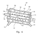
- Figure 6 is a cross-sectional view of a blood processing apparatus 100 in which blood flow through the heat exchanger portion is circumferential, while blood flow through the gas exchanger portion is longitudinal.
- the blood processing apparatus 100 includes a housing 102, a first end cap 104 and a second end cap 106.
- the blood processing apparatus 100 includes a blood inlet 108 and a blood outlet 110.
- a gas inlet 112 permits oxygen to be provided to the gas exchanger portion while a gas outlet 114 permits gases to exit the blood processing apparatus 100.
- the blood processing apparatus 100 includes a heat exchanger core 116, a heat exchanger element 118 disposed about the heat exchanger core 116, a cylindrical shell 120 disposed about the heat exchanger element 118 and a gas exchanger element 122, all disposed inside the outer shell or housing 102.
- the heat exchanger element 118 and the gas exchanger element 122 may each include a number of hollow fibers as discussed with respect to the blood processing apparatus 50.
- the housing 102 includes an annular portion 124 that is in fluid communication with the blood outlet 110.
- blood enters the blood processing apparatus 100 through the blood inlet 108 and passes into the heat exchanger core 116.
- the blood fills the heat exchanger core 116 and exits through an elongate core aperture 126 and thus enters the heat exchanger element 118.
- the heat exchanger core 116 includes a single elongate core aperture 126 while in other embodiments the heat exchanger core 116 may include two or more elongate core apertures 126.
- the elongate aperture 126 allows or directs blood to flow through the heat exchanger element 118 in a circumferential direction.
- the cylindrical shell 120 includes an elongate collector or channel 127.
- the channel 127 may be disposed at a location substantially diametrically opposed to the location of the elongate core aperture 126. Locating the channel 127 substantially opposite the location of the core aperture 126 causes blood to flow in a generally circumferential flow pattern within the heat exchanger element 118.
- the channel 127 may extend from between about 1 and about 15 degrees about the circumference of the cylindrical shell 120. In one exemplary embodiment, the channel 127 extends about 5 degrees about the circumference.
- the shell aperture 128, in various embodiments, extends entirely or substantially around the circumference of the cylindrical shell 120, such that blood exits the inner cylindrical shell 120 around the entire or substantially the entire circumference of the shell 120.
- the radially disposed shell aperture 128 may be located near an end of the blood processing apparatus 100 that is opposite the blood outlet 110, thereby causing the blood to flow through the gas exchanger element 122 in a longitudinal direction. Blood then collects in the annular portion 124 before exiting the blood processing apparatus 100 through the blood outlet 110.
- Figure 7 is a cross-sectional view of a blood processing apparatus 150 in which blood flow through the heat exchanger portion is longitudinal while blood flow through the gas exchanger portion is either radial or circumferential.
- the blood processing apparatus 150 includes a housing 152, a first end cap 154 and a second end cap 156.
- the blood processing apparatus 150 includes a blood inlet 158 and a blood outlet 160.
- a gas inlet 162 permits oxygen to be provided to the gas exchanger portion while a gas outlet 164 permits gases to exit the blood processing apparatus 150.
- the blood processing apparatus 150 includes a heat exchanger core 170, a heat exchanger element 172 disposed about the heat exchanger core 170, a cylindrical shell 174 disposed about the heat exchanger element 172 and a gas exchanger element 176 disposed about the cylindrical shell 174.
- the heat exchanger element 172 and the gas exchanger element 176 may each include a number of hollow fibers as discussed above with respect to the blood processing apparatus 50.
- the heat exchanger core 170 includes a single core aperture 177 while in other embodiments the heat exchanger core 170 may include two or more core apertures 177.
- the core aperture 177 may extend partially or entirely around the circumference of heat exchanger core 170.
- the blood enters the heat exchanger element 172 at a first end near the blood inlet 158.
- the blood then flows longitudinally through the heat exchanger element 172 and exits through a radially disposed shell aperture 178 in the cylindrical shell 174.
- the radially disposed shell aperture 178 is located at a second end that is opposite the first end, thereby causing the blood to flow in a longitudinal direction through the heat exchanger element 172.
- the blood After blood passes through the heat exchanger element 172, the blood exits the inner cylindrical shell 174 through the radially disposed shell aperture 178 and enters an elongate collector 180 that is disposed between the cylindrical shell 174 and the gas exchanger element 176.
- the collector 180 is formed in the cylindrical shell 174.
- the elongate collector 180 is configured to permit blood exiting the elongate collector 180 and entering the gas exchanger element 176 to flow in a circumferential direction.
- the elongate collector 180 may include an elongate channel or may include one or more apertures disposed longitudinally along the gas exchanger element 176.
- the blood flow exits at one circumferential location, such that blood flows through the gas exchanger element along a generally cylindrical flow path.
- the elongate collector 180 includes a plurality or channel or apertures disposed at various locations about the circumference of the elongate collector, such that blood flows through the gas exchanger element 176 in a generally radial direction. Blood exiting the gas exchanger element 176 passes into a tapered portion 182 that directs the blood through the blood outlet 160.
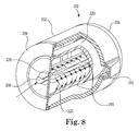
- Figures 8-10 show various views of a blood processing apparatus 200 where blood flow through the heat exchanger portion is both circumferential and radial, while blood flow through the gas exchanger portion is circumferential.
- the blood processing apparatus 200 includes a housing 202, a first end cap 204 and a second end cap 206.
- the blood processing apparatus 200 includes a blood inlet 208 and a blood outlet 210.
- the blood processing apparatus 200 includes a core 216, a heat exchanger element 218 disposed about the core 216, a cylindrical shell 220 disposed about the heat exchanger element 218, and a gas exchanger element 222 disposed about the cylindrical shell 220.
- the heat exchanger element 218 and the gas exchanger element 222 may each include a number of hollow fibers as discussed above with respect to the blood processing apparatus 50.
- the blood enters through the blood inlet 208 and passes into the core 216.
- the blood fills the core 216 and exits through a series of core apertures 226.
- the apertures are arranged to form a first elongate row and a second elongate row, with each row generally parallel to and in close proximity to the other row.
- the core 216 includes a first elongate channel and a second elongate channel, with each channel generally parallel to and in close proximity to the other channel.
- the elongate core apertures 226 permit blood to flow through the heat exchanger element 118 in a circumferential direction.
- the core apertures 226 are configured such that blood exiting the core 216 will flow through each of the first and second rows or channels, with blood exiting the first row or channel deflected or directed in a first circumferential direction and blood exiting the second row or channel deflected or directed in a second circumferential direction.
- blood flow thus exits the core and flows in a circumferential fashion through the heat exchanger element 218, with some blood flowing in one direction and some blood flowing in an opposite direction.
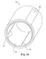
- FIG 10 is a perspective view of the cylindrical shell 220 according to various exemplary embodiments.
- the cylindrical shell 220 includes an inner surface 230.
- one or more elongate shell ribs or lobes 232 may be disposed on the inner surface 230 and may be configured to cause at least some of the blood flowing past the one or more shell ribs or lobes 232 to demonstrate a modified circumferential flow, which includes a radial flow component.
- the inner surface 230 of the cylindrical shell 220 may have between two and eight distinct lobes 232, and in one embodiment the inner surface 230 has four lobes 232.
- the lobes 232 are formed by adding additional material the inner surface, such that the internal diameter of the cylindrical shell 220, at the point where one lobe meets another lobe, is reduced by between about 5 and about 20 percent. In other embodiments, the lobes 232 are formed by removing material from the inner surface 230 or by some combination of adding and removing material.
- the blood will contact the lobes 232, which will in turn impart a radial flow component on the blood.
- the blood will then be flowing through the heat exchanger element 218 with an overall flow configuration that includes both a circumferential flow component and a radial flow component.
- the arrows shown in the heat exchanger element 218 in Figure 9 represent the blood flow pattern caused by the lobes 232, according to this exemplary embodiment.
- the core 216 includes exterior channels 217. As shown in Figure 9 , the core 216 includes four channels 217. In various embodiments, the channels are configures to further enhance the radial flow component of the blood. In various embodiments, the channels 217 are disposed at a location on the perimeter of the core 216 that is configured to cooperate with the lobes 232 formed in the inside surface of the cylindrical shell 220. For example, the channels 217 and lobes 232 may be circumferentially offset from one another such that blood is deflected radially inward by the lobes 232, simultaneous continued to move in the circumferential flow pattern, then is deflected radially outward by the channels 217. This configuration may then continue around the entire circumference of the core 216. In this manner, the combined radial and circumferential flow pattern of blood within the heat exchanger element 218 may be enhanced.
- Figure 11 is a perspective view of the heat exchanger core 216.
- the heat exchanger core 216 has an outer surface 234.
- one or more elongate core ribs 236 may be disposed on the inner surface 234 and may be configured to cause at least some of the blood flowing past the one or more elongate core ribs 236 to demonstrate a modified circumferential flow (e.g., to have both a circumferential and a radial flow component).
- the outer surface 234 may include a plurality of transverse ribs 238.
- the radially disposed ribs 238 extend radially outward from the core 216 to provide a space between the heat exchanger core 216 and the hollow fibers wrapped about the core 216. This space enhances blood flow around the fibers, which enhances heat transfer and reduces pressure drop in the heat exchanger.
- the ribs are disposed along substantially the entire effective length of the heat exchanger core 216. The ribs may be disposed generally transverse to a longitudinal axis of the core 216.
- the blood After blood passes through the heat exchanger element 218, the blood exits the cylindrical shell 220 through an elongate shell aperture 228.
- the elongate shell aperture 228 may be diametrically opposed from the elongate core aperture 226, thereby causing blood to flow in a circumferential direction.
- the blood enters the gas exchange element 222 and passes circumferentially towards the blood outlet 210.
Landscapes
- Health & Medical Sciences (AREA)
- Engineering & Computer Science (AREA)
- Heart & Thoracic Surgery (AREA)
- Vascular Medicine (AREA)
- Thermal Sciences (AREA)
- Physics & Mathematics (AREA)
- General Engineering & Computer Science (AREA)
- Mechanical Engineering (AREA)
- Life Sciences & Earth Sciences (AREA)
- Anesthesiology (AREA)
- Animal Behavior & Ethology (AREA)
- General Health & Medical Sciences (AREA)
- Public Health (AREA)
- Veterinary Medicine (AREA)
- Hematology (AREA)
- Biomedical Technology (AREA)
- Cardiology (AREA)
- Emergency Medicine (AREA)
- Urology & Nephrology (AREA)
- Pulmonology (AREA)
- Chemical & Material Sciences (AREA)
- Chemical Kinetics & Catalysis (AREA)
- External Artificial Organs (AREA)
Priority Applications (8)
| Application Number | Priority Date | Filing Date | Title |
|---|---|---|---|
| EP12187501.7A EP2543403B1 (de) | 2010-08-19 | 2010-11-15 | Blutverarbeitungseinheit mit umlaufender Blutsströmung |
| EP10191140.2A EP2420263B1 (de) | 2010-08-19 | 2010-11-15 | Blutverarbeitungseinheit mit umlaufender Blutsströmung |
| US12/947,171 US8795220B2 (en) | 2010-08-19 | 2010-11-16 | Blood processing unit with circumferential blood flow |
| BR112013009973A BR112013009973A2 (pt) | 2010-11-15 | 2011-10-21 | unidade de processamento de sangue com fluxo de sangue circunferencial |
| JP2013538297A JP5913345B2 (ja) | 2010-11-15 | 2011-10-21 | 円周方向血液流れの血液処理ユニット |
| CN201180054953.0A CN103209722B (zh) | 2010-11-15 | 2011-10-21 | 具有周向血液流动的血液处理单元 |
| PCT/IB2011/054725 WO2012066439A1 (en) | 2010-11-15 | 2011-10-21 | Blood processing unit with circumferential blood flow |
| JP2016023341A JP6082485B2 (ja) | 2010-11-15 | 2016-02-10 | 円周方向血液流れの血液処理ユニット |
Applications Claiming Priority (2)
| Application Number | Priority Date | Filing Date | Title |
|---|---|---|---|
| EP10173436.6A EP2420262B1 (de) | 2010-08-19 | 2010-08-19 | Blutverarbeitungseinheit mit modifiziertem Fließpfad |
| EP10191140.2A EP2420263B1 (de) | 2010-08-19 | 2010-11-15 | Blutverarbeitungseinheit mit umlaufender Blutsströmung |
Related Child Applications (2)
| Application Number | Title | Priority Date | Filing Date |
|---|---|---|---|
| EP12187501.7A Division-Into EP2543403B1 (de) | 2010-08-19 | 2010-11-15 | Blutverarbeitungseinheit mit umlaufender Blutsströmung |
| EP12187501.7A Division EP2543403B1 (de) | 2010-08-19 | 2010-11-15 | Blutverarbeitungseinheit mit umlaufender Blutsströmung |
Publications (2)
| Publication Number | Publication Date |
|---|---|
| EP2420263A1 true EP2420263A1 (de) | 2012-02-22 |
| EP2420263B1 EP2420263B1 (de) | 2015-06-17 |
Family
ID=43425894
Family Applications (4)
| Application Number | Title | Priority Date | Filing Date |
|---|---|---|---|
| EP13161841.5A Active EP2612685B1 (de) | 2010-08-19 | 2010-08-19 | Blutverarbeitungseinheit mit modifiziertem Fließpfad |
| EP10173436.6A Active EP2420262B1 (de) | 2010-08-19 | 2010-08-19 | Blutverarbeitungseinheit mit modifiziertem Fließpfad |
| EP10191140.2A Not-in-force EP2420263B1 (de) | 2010-08-19 | 2010-11-15 | Blutverarbeitungseinheit mit umlaufender Blutsströmung |
| EP12187501.7A Not-in-force EP2543403B1 (de) | 2010-08-19 | 2010-11-15 | Blutverarbeitungseinheit mit umlaufender Blutsströmung |
Family Applications Before (2)
| Application Number | Title | Priority Date | Filing Date |
|---|---|---|---|
| EP13161841.5A Active EP2612685B1 (de) | 2010-08-19 | 2010-08-19 | Blutverarbeitungseinheit mit modifiziertem Fließpfad |
| EP10173436.6A Active EP2420262B1 (de) | 2010-08-19 | 2010-08-19 | Blutverarbeitungseinheit mit modifiziertem Fließpfad |
Family Applications After (1)
| Application Number | Title | Priority Date | Filing Date |
|---|---|---|---|
| EP12187501.7A Not-in-force EP2543403B1 (de) | 2010-08-19 | 2010-11-15 | Blutverarbeitungseinheit mit umlaufender Blutsströmung |
Country Status (2)
| Country | Link |
|---|---|
| US (7) | US8394049B2 (de) |
| EP (4) | EP2612685B1 (de) |
Cited By (1)
| Publication number | Priority date | Publication date | Assignee | Title |
|---|---|---|---|---|
| CN110958912A (zh) * | 2017-07-28 | 2020-04-03 | 东洋纺株式会社 | 中空纤维膜组件 |
Families Citing this family (19)
| Publication number | Priority date | Publication date | Assignee | Title |
|---|---|---|---|---|
| US8318092B2 (en) | 2010-04-29 | 2012-11-27 | Sorin Group Italia S.R.L. | Oxygenator with integrated arterial filter |
| US8388566B2 (en) | 2010-04-29 | 2013-03-05 | Sorin Group Italia, S.r.l. | Oxygenator with integrated arterial filter including filter frame |
| EP2612685B1 (de) | 2010-08-19 | 2014-10-08 | Sorin Group Italia S.r.l. | Blutverarbeitungseinheit mit modifiziertem Fließpfad |
| EP2524712B1 (de) * | 2011-05-17 | 2018-12-12 | Sorin Group Italia S.r.l. | Blutverarbeitungseinheit mit Blutquerstrom |
| EP3092015B1 (de) | 2014-01-09 | 2018-09-19 | Sorin Group Italia S.r.l. | Blutverarbeitungseinheit mit einem wärmetauscherkern zur bereitstellung eines modifizierten fliesspfades |
| JP6386580B2 (ja) | 2014-02-28 | 2018-09-05 | ソリン・グループ・イタリア・ソシエタ・ア・レスポンサビリタ・リミタータSorin Group Italia S.r.l. | 追加される充填量を最小にする、酸素供給器と一体化される動脈フィルタを提供するためのシステム |
| EP3131663A2 (de) | 2014-03-29 | 2017-02-22 | Princeton Trade and Technology Inc. | Blutverarbeitungskartuschen und systeme sowie verfahren für extrakorporale bluttherapien |
| US10589015B2 (en) | 2014-10-20 | 2020-03-17 | The Regents Of The University Of Michigan | Gated-concentric artificial lung |
| JP6490216B2 (ja) | 2014-11-12 | 2019-03-27 | ソリン・グループ・イタリア・ソシエタ・ア・レスポンサビリタ・リミタータSorin Group Italia S.r.l. | 中空繊維血液処理装置用の弾性保護管 |
| WO2016181189A1 (en) | 2015-05-12 | 2016-11-17 | Sorin Group Italia S.R.L. | Blood gas exchanger with restriction element or elements to reduce gas exchange |
| US10426884B2 (en) | 2015-06-26 | 2019-10-01 | Novaflux Inc. | Cartridges and systems for outside-in flow in membrane-based therapies |
| US10399040B2 (en) | 2015-09-24 | 2019-09-03 | Novaflux Inc. | Cartridges and systems for membrane-based therapies |
| KR101762228B1 (ko) * | 2015-11-27 | 2017-07-27 | 재단법인 아산사회복지재단 | 혈액 산화기 |
| EP3515528A1 (de) | 2016-09-22 | 2019-07-31 | Christopher J Plott | Vorrichtungen und verfahren zur extrakorporalen aufbereitung von blut |
| JP6994052B2 (ja) | 2017-06-01 | 2022-01-14 | ソリン・グループ・イタリア・ソシエタ・ア・レスポンサビリタ・リミタータ | 断熱性を有する人工肺 |
| EP3668556A4 (de) | 2017-08-15 | 2021-06-23 | University of Maryland, Baltimore | Zweikammer-gasaustauscher und verfahren zur verwendung zur unterstützung der atmung |
| JP6948465B2 (ja) * | 2017-10-10 | 2021-10-13 | ソリン・グループ・イタリア・ソシエタ・ア・レスポンサビリタ・リミタータSorin Group Italia S.r.l. | 熱交換器(hex)内の向流血液/水流路を備えた血液処理ユニット(bpu) |
| US11541157B2 (en) | 2019-06-18 | 2023-01-03 | Michigan Critical Care Consultants, Inc. | Membrane oxygenator with gas exchange fiber lumen access based on fiber effective length |
| US11925739B2 (en) | 2019-10-23 | 2024-03-12 | Seagate Technology Llc | Artificial kidney |
Citations (6)
| Publication number | Priority date | Publication date | Assignee | Title |
|---|---|---|---|---|
| US5578267A (en) * | 1992-05-11 | 1996-11-26 | Minntech Corporation | Cylindrical blood heater/oxygenator |
| WO1997019714A1 (en) * | 1995-11-30 | 1997-06-05 | Minnesota Mining And Manufacturing Company | Blood oxygenator and heat exchanger |
| WO1997033636A1 (en) * | 1996-01-11 | 1997-09-18 | Medtronic, Inc. | Blood oxygenator with heat exchanger |
| US5817278A (en) * | 1994-11-25 | 1998-10-06 | Dideco S.P.A. | Blood oxygenator and method of oxygenating blood |
| US20040175292A1 (en) * | 2000-08-08 | 2004-09-09 | Dideco S.P.A. | Device for oxygenating blood in an extracorporeal circuit |
| EP1834656A1 (de) * | 2006-03-17 | 2007-09-19 | Eurosets S.r.l. | Integrierte Vorrichtung zum Erwärmen und Anreichern mit Sauerstoff von Blut in einem extrakorporalen Kreislauf |
Family Cites Families (102)
| Publication number | Priority date | Publication date | Assignee | Title |
|---|---|---|---|---|
| US3339341A (en) | 1965-12-22 | 1967-09-05 | Du Pont | Fluid separation process and apparatus |
| JPS445526Y1 (de) | 1968-07-22 | 1969-02-28 | ||
| FR2214502B1 (de) * | 1973-01-18 | 1976-05-14 | Rhone Poulenc Ind | |
| FR2231421B1 (de) | 1973-05-30 | 1976-05-07 | Rhone Poulenc Ind | |
| JPS52126681A (en) | 1976-04-16 | 1977-10-24 | Asahi Chem Ind Co Ltd | Improved hollow fiber fluid separating apparatus |
| SE421999B (sv) | 1977-10-17 | 1982-02-15 | Gambro Dialysatoren | Anordning for diffusion och/eller filtration av emnen mellan tva fluider via semipermeabla membran vilken anordning innefattar parallellkopplade banor innehallande seriekopplade kamrar |
| IT1091268B (it) * | 1977-12-15 | 1985-07-06 | Hospal Dasco Spa | Perfezionamento ad un emodializzatore |
| JPS5935631B2 (ja) | 1980-07-24 | 1984-08-29 | テルモ株式会社 | 体液「ろ」過装置 |
| US4707268A (en) | 1982-10-18 | 1987-11-17 | Baxter Travenol Laboratories, Inc. | Hollow fiber potted microfilter |
| US4902476A (en) | 1983-01-14 | 1990-02-20 | Baxter International Inc. | Heat exchanger and blood oxygenator apparatus |
| JPS59147603A (ja) | 1983-02-10 | 1984-08-24 | Kuraray Co Ltd | 保護体付き中空糸束 |
| JPS6053156A (ja) | 1983-09-01 | 1985-03-26 | 三菱レイヨン株式会社 | 血液浄化器 |
| EP0312125B1 (de) | 1983-11-11 | 1992-03-04 | TERUMO KABUSHIKI KAISHA trading as TERUMO CORPORATION | Einrichtung zum Aufnehmen und Behandeln von Blut |
| CA1251109A (en) | 1984-04-24 | 1989-03-14 | Tohru Takemura | Blood oxygenator using a hollow-fiber membrane |
| CA1258436A (en) | 1984-08-01 | 1989-08-15 | Michael A. Smoot | Mat structure for use in filtration devices |
| JPS63139562A (ja) | 1986-12-01 | 1988-06-11 | 株式会社 日本メデイカル・サプライ | 中空糸型人工肺 |
| US4758341A (en) | 1987-04-20 | 1988-07-19 | The Dow Chemical Company | Membrane separation device |
| JPS6440060A (en) | 1987-08-06 | 1989-02-10 | Ube Industries | Artificial lung provided with built-in heat exchanger |
| JPS6476868A (en) | 1987-09-18 | 1989-03-22 | Nippon Medical Supply | Improved pump-oxygenator |
| US5120501A (en) | 1988-10-20 | 1992-06-09 | Baxter International Inc. | Integrated membrane blood oxygenator/heat exchanger |
| US5316724A (en) * | 1989-03-31 | 1994-05-31 | Baxter International Inc. | Multiple blood path membrane oxygenator |
| JPH0347271A (ja) | 1989-07-14 | 1991-02-28 | Terumo Corp | 液体処理器 |
| US5270004A (en) | 1989-10-01 | 1993-12-14 | Minntech Corporation | Cylindrical blood heater/oxygenator |
| EP0519132A1 (de) * | 1989-10-18 | 1992-12-23 | Exxon Research And Engineering Company | Hohlfasermodul |
| JPH03169329A (ja) | 1989-11-30 | 1991-07-23 | Nok Corp | 中空糸膜モジュールの製造方法 |
| JP3228518B2 (ja) | 1990-12-14 | 2001-11-12 | 日機装株式会社 | 人工心肺装置 |
| JPH05177117A (ja) | 1991-10-23 | 1993-07-20 | Hisateru Takano | 物質交換装置 |
| JP3284568B2 (ja) | 1991-10-31 | 2002-05-20 | 株式会社ジェイ・エム・エス | 人工肺用入口ヘッダーおよびそれを使用した人工肺 |
| US5192439A (en) | 1992-02-03 | 1993-03-09 | Electromedics, Inc. | Blood collection reservoir and filter device |
| WO1994003266A1 (en) | 1992-08-03 | 1994-02-17 | Maloney James V Jr | Improved mass and thermal transfer means for use in heart lung machines, dialyzers, and other applications |
| IT1255820B (it) * | 1992-08-10 | 1995-11-16 | Nicola Ghelli | Scambiatore di calore in circuito ematico extracorporeo |
| US5489413A (en) * | 1992-11-03 | 1996-02-06 | Cobe Laboratories, Inc. | Hollow fiber blood oxygenator |
| US5501663A (en) | 1993-07-02 | 1996-03-26 | Medtronic Electromedics, Inc. | Inflatable percutaneous oxygenator with transverse hollow fibers |
| US5514095A (en) | 1994-04-04 | 1996-05-07 | Haemonetics Corporation | Apparatus for heating, filtering and eliminating gas from biological fluids |
| JPH08168525A (ja) | 1994-12-19 | 1996-07-02 | Terumo Corp | 中空糸膜型血液処理器の製造方法及びその製造装置 |
| US5651765A (en) | 1995-04-27 | 1997-07-29 | Avecor Cardiovascular Inc. | Blood filter with concentric pleats and method of use |
| EP0765683B1 (de) | 1995-09-25 | 1998-07-01 | MEDOS Medizintechnik GmbH | Vorrichtung zur Behandlung von Flüssigkeiten, insbesondere von Blut |
| US5770149A (en) | 1995-10-31 | 1998-06-23 | Baxter International | Extracorporeal blood oxygenation system having integrated blood pump, heat exchanger and membrane oxygenator |
| SE506613C2 (sv) * | 1996-05-30 | 1998-01-19 | Votinex Management Sa | Filter- och värmeväxlaranordning |
| US5762869A (en) * | 1996-07-24 | 1998-06-09 | Gish Biomedical, Inc. | Blood oxygenator |
| JP3574902B2 (ja) | 1996-11-15 | 2004-10-06 | サイテック株式会社 | 中空糸型ダイアライザー |
| JPH1147268A (ja) | 1997-08-06 | 1999-02-23 | Terumo Corp | 中空糸膜型人工肺 |
| US6241945B1 (en) | 1998-03-16 | 2001-06-05 | Life Science Holdings, Inc. | Modular combined pump, filtration, oxygenation and/or debubbler apparatus |
| BR9910313B1 (pt) | 1998-05-08 | 2008-11-18 | reservatàrio de sangue/permutador tÉrmico combinado. | |
| US6113782A (en) | 1998-07-28 | 2000-09-05 | Terumo Cardiovascular Systems Corporation | Potting of tubular bundles in housing |
| US6193681B1 (en) | 1998-09-14 | 2001-02-27 | American Immuno Tech, Llc. | Septicemia prevention and treatment system |
| JP3992377B2 (ja) | 1998-09-18 | 2007-10-17 | テルモ株式会社 | 熱交換機能内蔵中空糸膜型人工肺 |
| US6454999B1 (en) * | 1998-12-30 | 2002-09-24 | Cardiovention, Inc. | Integrated blood pump and oxygenator system having extended blood flow path |
| JP4041254B2 (ja) * | 1999-12-15 | 2008-01-30 | テルモ株式会社 | 中空糸膜型人工肺 |
| DE50113701D1 (de) | 2000-03-07 | 2008-04-17 | Mat Adsorption Technologies Gm | Modul mit membranelementen in cross-flow und in dead-end anordnung |
| US6459937B1 (en) | 2000-04-25 | 2002-10-01 | Pacesetter, Inc. | Endocardial pacing lead with detachable tip electrode assembly |
| US6730267B2 (en) | 2001-02-09 | 2004-05-04 | Cardiovention, Inc. | Integrated blood handling system having active gas removal system and methods of use |
| US6755894B2 (en) * | 2001-05-02 | 2004-06-29 | Praxair Technology, Inc. | Hollow fiber membrane gas separation cartridge and gas purification assembly |
| US6623638B2 (en) | 2001-06-01 | 2003-09-23 | Baxter International Inc. | Hemodialyzer having improved dialysate perfusion |
| US7156155B2 (en) * | 2001-09-25 | 2007-01-02 | Honda Motor Co., Ltd. | Heat storage unit and manufacturing method therefor |
| CN2511309Y (zh) | 2001-11-16 | 2002-09-18 | 广东省医疗器械研究所 | 膜式氧合器 |
| US20030175149A1 (en) | 2002-03-18 | 2003-09-18 | Bruce Searles | Renewable, modifiable, membrane gas exchanger |
| DE60331403D1 (de) | 2002-12-26 | 2010-04-08 | Nipro Corp | Dialysator und dessen Herstellungsverfahren |
| JP4214910B2 (ja) | 2002-12-26 | 2009-01-28 | ニプロ株式会社 | 透析器およびその製造方法 |
| JP4218433B2 (ja) | 2003-06-13 | 2009-02-04 | 株式会社Sumco | 単結晶棒引上げ用ワイヤの荷重付加装置 |
| JP4337573B2 (ja) | 2004-02-10 | 2009-09-30 | 株式会社ジェイ・エム・エス | 熱交換器、その製造方法及び人工心肺装置 |
| DE102004012049B4 (de) | 2004-03-11 | 2006-02-09 | Siemens Ag | Verfahren zum Befestigen eines Blechpaketes für die Statorwicklung eines Linearmotors am Fahrweg |
| CN2772515Y (zh) | 2004-04-23 | 2006-04-19 | 广东省医疗器械研究所 | 一种中空纤维膜式氧合器 |
| JP4366268B2 (ja) | 2004-07-23 | 2009-11-18 | テルモ株式会社 | 人工肺 |
| DE102005031582A1 (de) | 2005-07-06 | 2007-01-11 | Maquet Cardiopulmonary Ag | Vorrichtung zur Behandlung von Blut in einem extrakorporalen Blutkreislauf |
| DE102005039446B4 (de) | 2005-08-18 | 2009-06-25 | Ilias-Medical Gmbh | Vorrichtung zur An- und Abreicherung von Stoffen in einer Flüssigkeit |
| DE602005022122D1 (de) | 2005-08-22 | 2010-08-12 | St Jude Medical | Werkzeug zur befestigung einer herzstimulatorleitung an einem gewünschten punkt im herz |
| US20070107884A1 (en) * | 2005-10-27 | 2007-05-17 | Sirkar Kamalesh K | Polymeric hollow fiber heat exchange systems |
| EP1810704B1 (de) * | 2006-01-19 | 2015-04-22 | Terumo Kabushiki Kaisha | Oxygenator |
| JP4500776B2 (ja) | 2006-01-19 | 2010-07-14 | テルモ株式会社 | 人工肺 |
| JP4855119B2 (ja) | 2006-03-28 | 2012-01-18 | テルモ株式会社 | フィルタ部材および人工肺 |
| JP4714082B2 (ja) | 2006-06-07 | 2011-06-29 | 株式会社東芝 | 屋外装置の発光素子表示構造 |
| DE102007010112A1 (de) | 2007-02-28 | 2008-09-04 | Rheinisch-Westfälische Technische Hochschule Aachen | Vorrichtung für den Stoff- und/oder Energieaustausch |
| KR100902674B1 (ko) | 2007-10-10 | 2009-06-15 | 엔에이치엔(주) | 문서 탐색 서비스 제공 방법 및 시스템 |
| JP5020111B2 (ja) | 2008-02-04 | 2012-09-05 | 株式会社小松製作所 | 油圧制御装置および油圧制御方法、油圧制御装置の調整方法 |
| US20100272607A1 (en) * | 2009-04-23 | 2010-10-28 | Carpenter Walt L | Radial design oxygenator with heat exchanger and inlet mandrel |
| US20100269342A1 (en) | 2009-04-23 | 2010-10-28 | Carpenter Walt L | Method of making radial design oxygenator with heat exchanger |
| EP2421576B1 (de) | 2009-04-23 | 2017-07-19 | Medtronic Inc. | Radialer oxygenator mit wärmeaustauscher |
| US20100272606A1 (en) | 2009-04-23 | 2010-10-28 | Carpenter Walt L | Radial flow oxygenator/heat exchanger |
| EP2295646B1 (de) | 2009-08-28 | 2012-06-27 | BAUER Maschinen GmbH | Bohrvorrichtung und Bohrverfahren |
| CN201510571U (zh) | 2009-09-29 | 2010-06-23 | 山东威高新生医疗器械有限公司 | 膜式氧合器 |
| JP5418275B2 (ja) | 2010-02-15 | 2014-02-19 | ニプロ株式会社 | 熱交換器および熱交換器一体型人工肺 |
| CN101837151B (zh) | 2010-03-19 | 2012-07-04 | 南方医科大学珠江医院 | 双向灌注式生物反应器控制系统和方法 |
| DE102010027973A1 (de) | 2010-04-20 | 2011-10-20 | Ilias-Medical Gmbh | Verfahren und Vorrichtung zur Herstellung eines Membranmodus |
| US8318092B2 (en) | 2010-04-29 | 2012-11-27 | Sorin Group Italia S.R.L. | Oxygenator with integrated arterial filter |
| US8388566B2 (en) | 2010-04-29 | 2013-03-05 | Sorin Group Italia, S.r.l. | Oxygenator with integrated arterial filter including filter frame |
| CA2800658C (en) | 2010-05-26 | 2018-09-11 | The Charles Stark Draper Laboratory, Inc. | Microfabricated artificial lung assist device, and methods of use and manufacture thereof |
| EP2612685B1 (de) | 2010-08-19 | 2014-10-08 | Sorin Group Italia S.r.l. | Blutverarbeitungseinheit mit modifiziertem Fließpfad |
| EP2524712B1 (de) | 2011-05-17 | 2018-12-12 | Sorin Group Italia S.r.l. | Blutverarbeitungseinheit mit Blutquerstrom |
| BR112013009973A2 (pt) | 2010-11-15 | 2016-08-02 | Sorin Group Italia Srl | unidade de processamento de sangue com fluxo de sangue circunferencial |
| US8518259B2 (en) | 2011-01-27 | 2013-08-27 | Medtronic, Inc. | De-airing oxygenator for treating blood in an extracorporeal blood circuit |
| CN201978219U (zh) | 2011-02-09 | 2011-09-21 | 朱宗涛 | 可控制流量的血液体外循环氧合器 |
| WO2012133372A1 (ja) | 2011-03-31 | 2012-10-04 | テルモ株式会社 | 人工肺 |
| US8865067B2 (en) | 2011-04-29 | 2014-10-21 | Medtronic, Inc. | Combination oxygenator and arterial filter device for treating blood in an extracorporeal blood circuit |
| US8685319B2 (en) | 2011-04-29 | 2014-04-01 | Medtronic, Inc. | Combination oxygenator and arterial filter device with a fiber bundle of continuously wound hollow fibers for treating blood in an extracorporeal blood circuit |
| WO2012163372A1 (de) | 2011-05-31 | 2012-12-06 | Ali Kashefi | Vorrichtung für den stoff- und/oder energieaustausch zwischen zwei medien |
| JP5844585B2 (ja) | 2011-09-15 | 2016-01-20 | ソリン・グループ・イタリア・ソシエタ・ア・レスポンサビリタ・リミタータ | 変更された流路を有する血液処理ユニット |
| EP3092015B1 (de) | 2014-01-09 | 2018-09-19 | Sorin Group Italia S.r.l. | Blutverarbeitungseinheit mit einem wärmetauscherkern zur bereitstellung eines modifizierten fliesspfades |
| CN106163584B (zh) | 2014-01-20 | 2019-03-19 | 优罗塞斯有限责任公司 | 用于病人血液体外氧合的装置 |
| JP6386580B2 (ja) | 2014-02-28 | 2018-09-05 | ソリン・グループ・イタリア・ソシエタ・ア・レスポンサビリタ・リミタータSorin Group Italia S.r.l. | 追加される充填量を最小にする、酸素供給器と一体化される動脈フィルタを提供するためのシステム |
| JP6490216B2 (ja) | 2014-11-12 | 2019-03-27 | ソリン・グループ・イタリア・ソシエタ・ア・レスポンサビリタ・リミタータSorin Group Italia S.r.l. | 中空繊維血液処理装置用の弾性保護管 |
| WO2016181189A1 (en) | 2015-05-12 | 2016-11-17 | Sorin Group Italia S.R.L. | Blood gas exchanger with restriction element or elements to reduce gas exchange |
-
2010
- 2010-08-19 EP EP13161841.5A patent/EP2612685B1/de active Active
- 2010-08-19 EP EP10173436.6A patent/EP2420262B1/de active Active
- 2010-08-20 US US12/860,062 patent/US8394049B2/en active Active
- 2010-11-15 EP EP10191140.2A patent/EP2420263B1/de not_active Not-in-force
- 2010-11-15 EP EP12187501.7A patent/EP2543403B1/de not_active Not-in-force
- 2010-11-16 US US12/947,171 patent/US8795220B2/en active Active
-
2013
- 2013-01-30 US US13/753,638 patent/US8652406B2/en active Active
-
2014
- 2014-01-16 US US14/156,937 patent/US9402943B2/en active Active
-
2016
- 2016-07-20 US US15/215,527 patent/US10159777B2/en active Active
-
2018
- 2018-11-28 US US16/203,483 patent/US11160912B2/en active Active
-
2021
- 2021-10-07 US US17/496,330 patent/US20220023519A1/en active Pending
Patent Citations (6)
| Publication number | Priority date | Publication date | Assignee | Title |
|---|---|---|---|---|
| US5578267A (en) * | 1992-05-11 | 1996-11-26 | Minntech Corporation | Cylindrical blood heater/oxygenator |
| US5817278A (en) * | 1994-11-25 | 1998-10-06 | Dideco S.P.A. | Blood oxygenator and method of oxygenating blood |
| WO1997019714A1 (en) * | 1995-11-30 | 1997-06-05 | Minnesota Mining And Manufacturing Company | Blood oxygenator and heat exchanger |
| WO1997033636A1 (en) * | 1996-01-11 | 1997-09-18 | Medtronic, Inc. | Blood oxygenator with heat exchanger |
| US20040175292A1 (en) * | 2000-08-08 | 2004-09-09 | Dideco S.P.A. | Device for oxygenating blood in an extracorporeal circuit |
| EP1834656A1 (de) * | 2006-03-17 | 2007-09-19 | Eurosets S.r.l. | Integrierte Vorrichtung zum Erwärmen und Anreichern mit Sauerstoff von Blut in einem extrakorporalen Kreislauf |
Cited By (1)
| Publication number | Priority date | Publication date | Assignee | Title |
|---|---|---|---|---|
| CN110958912A (zh) * | 2017-07-28 | 2020-04-03 | 东洋纺株式会社 | 中空纤维膜组件 |
Also Published As
| Publication number | Publication date |
|---|---|
| EP2543403A3 (de) | 2013-12-18 |
| US20130142696A1 (en) | 2013-06-06 |
| US8394049B2 (en) | 2013-03-12 |
| EP2420263B1 (de) | 2015-06-17 |
| EP2420262B1 (de) | 2013-04-17 |
| US8652406B2 (en) | 2014-02-18 |
| US20120046594A1 (en) | 2012-02-23 |
| EP2420262A1 (de) | 2012-02-22 |
| EP2543403B1 (de) | 2014-12-17 |
| US9402943B2 (en) | 2016-08-02 |
| US20220023519A1 (en) | 2022-01-27 |
| EP2612685B1 (de) | 2014-10-08 |
| EP2612685A1 (de) | 2013-07-10 |
| US20120121463A1 (en) | 2012-05-17 |
| US8795220B2 (en) | 2014-08-05 |
| US20160354529A1 (en) | 2016-12-08 |
| US10159777B2 (en) | 2018-12-25 |
| US20190091395A1 (en) | 2019-03-28 |
| EP2543403A2 (de) | 2013-01-09 |
| US11160912B2 (en) | 2021-11-02 |
| US20140227133A1 (en) | 2014-08-14 |
Similar Documents
| Publication | Publication Date | Title |
|---|---|---|
| EP2420263B1 (de) | Blutverarbeitungseinheit mit umlaufender Blutsströmung | |
| EP2524712B1 (de) | Blutverarbeitungseinheit mit Blutquerstrom | |
| JP6082485B2 (ja) | 円周方向血液流れの血液処理ユニット | |
| JP5913345B2 (ja) | 円周方向血液流れの血液処理ユニット | |
| EP3092015B1 (de) | Blutverarbeitungseinheit mit einem wärmetauscherkern zur bereitstellung eines modifizierten fliesspfades | |
| JP5844585B2 (ja) | 変更された流路を有する血液処理ユニット | |
| JP6030210B2 (ja) | 変更された流路を有する血液処理ユニット | |
| US10814056B2 (en) | Elastic protection tube for a hollow fiber blood processing apparatus | |
| US20240165310A1 (en) | Blood processing unit (bpu) with countercurrent blood/water flow paths in the heat exchanger (hex) |
Legal Events
| Date | Code | Title | Description |
|---|---|---|---|
| AK | Designated contracting states |
Kind code of ref document: A1 Designated state(s): AL AT BE BG CH CY CZ DE DK EE ES FI FR GB GR HR HU IE IS IT LI LT LU LV MC MK MT NL NO PL PT RO RS SE SI SK SM TR |
|
| AX | Request for extension of the european patent |
Extension state: BA ME |
|
| PUAI | Public reference made under article 153(3) epc to a published international application that has entered the european phase |
Free format text: ORIGINAL CODE: 0009012 |
|
| 17P | Request for examination filed |
Effective date: 20120810 |
|
| RAP1 | Party data changed (applicant data changed or rights of an application transferred) |
Owner name: SORIN GROUP ITALIA S.R.L. |
|
| 17Q | First examination report despatched |
Effective date: 20131120 |
|
| GRAP | Despatch of communication of intention to grant a patent |
Free format text: ORIGINAL CODE: EPIDOSNIGR1 |
|
| INTG | Intention to grant announced |
Effective date: 20150127 |
|
| GRAS | Grant fee paid |
Free format text: ORIGINAL CODE: EPIDOSNIGR3 |
|
| GRAA | (expected) grant |
Free format text: ORIGINAL CODE: 0009210 |
|
| AK | Designated contracting states |
Kind code of ref document: B1 Designated state(s): AL AT BE BG CH CY CZ DE DK EE ES FI FR GB GR HR HU IE IS IT LI LT LU LV MC MK MT NL NO PL PT RO RS SE SI SK SM TR |
|
| REG | Reference to a national code |
Ref country code: GB Ref legal event code: FG4D |
|
| REG | Reference to a national code |
Ref country code: CH Ref legal event code: EP |
|
| REG | Reference to a national code |
Ref country code: AT Ref legal event code: REF Ref document number: 731548 Country of ref document: AT Kind code of ref document: T Effective date: 20150715 |
|
| REG | Reference to a national code |
Ref country code: IE Ref legal event code: FG4D |
|
| REG | Reference to a national code |
Ref country code: DE Ref legal event code: R096 Ref document number: 602010025250 Country of ref document: DE |
|
| REG | Reference to a national code |
Ref country code: FR Ref legal event code: PLFP Year of fee payment: 6 |
|
| PG25 | Lapsed in a contracting state [announced via postgrant information from national office to epo] |
Ref country code: LT Free format text: LAPSE BECAUSE OF FAILURE TO SUBMIT A TRANSLATION OF THE DESCRIPTION OR TO PAY THE FEE WITHIN THE PRESCRIBED TIME-LIMIT Effective date: 20150617 Ref country code: HR Free format text: LAPSE BECAUSE OF FAILURE TO SUBMIT A TRANSLATION OF THE DESCRIPTION OR TO PAY THE FEE WITHIN THE PRESCRIBED TIME-LIMIT Effective date: 20150617 Ref country code: FI Free format text: LAPSE BECAUSE OF FAILURE TO SUBMIT A TRANSLATION OF THE DESCRIPTION OR TO PAY THE FEE WITHIN THE PRESCRIBED TIME-LIMIT Effective date: 20150617 Ref country code: NO Free format text: LAPSE BECAUSE OF FAILURE TO SUBMIT A TRANSLATION OF THE DESCRIPTION OR TO PAY THE FEE WITHIN THE PRESCRIBED TIME-LIMIT Effective date: 20150917 |
|
| REG | Reference to a national code |
Ref country code: NL Ref legal event code: FP |
|
| REG | Reference to a national code |
Ref country code: AT Ref legal event code: MK05 Ref document number: 731548 Country of ref document: AT Kind code of ref document: T Effective date: 20150617 |
|
| REG | Reference to a national code |
Ref country code: LT Ref legal event code: MG4D |
|
| PG25 | Lapsed in a contracting state [announced via postgrant information from national office to epo] |
Ref country code: LV Free format text: LAPSE BECAUSE OF FAILURE TO SUBMIT A TRANSLATION OF THE DESCRIPTION OR TO PAY THE FEE WITHIN THE PRESCRIBED TIME-LIMIT Effective date: 20150617 Ref country code: GR Free format text: LAPSE BECAUSE OF FAILURE TO SUBMIT A TRANSLATION OF THE DESCRIPTION OR TO PAY THE FEE WITHIN THE PRESCRIBED TIME-LIMIT Effective date: 20150918 Ref country code: RS Free format text: LAPSE BECAUSE OF FAILURE TO SUBMIT A TRANSLATION OF THE DESCRIPTION OR TO PAY THE FEE WITHIN THE PRESCRIBED TIME-LIMIT Effective date: 20150617 Ref country code: BG Free format text: LAPSE BECAUSE OF FAILURE TO SUBMIT A TRANSLATION OF THE DESCRIPTION OR TO PAY THE FEE WITHIN THE PRESCRIBED TIME-LIMIT Effective date: 20150917 |
|
| PG25 | Lapsed in a contracting state [announced via postgrant information from national office to epo] |
Ref country code: EE Free format text: LAPSE BECAUSE OF FAILURE TO SUBMIT A TRANSLATION OF THE DESCRIPTION OR TO PAY THE FEE WITHIN THE PRESCRIBED TIME-LIMIT Effective date: 20150617 |
|
| PG25 | Lapsed in a contracting state [announced via postgrant information from national office to epo] |
Ref country code: RO Free format text: LAPSE BECAUSE OF NON-PAYMENT OF DUE FEES Effective date: 20150617 Ref country code: PT Free format text: LAPSE BECAUSE OF FAILURE TO SUBMIT A TRANSLATION OF THE DESCRIPTION OR TO PAY THE FEE WITHIN THE PRESCRIBED TIME-LIMIT Effective date: 20151019 Ref country code: CZ Free format text: LAPSE BECAUSE OF FAILURE TO SUBMIT A TRANSLATION OF THE DESCRIPTION OR TO PAY THE FEE WITHIN THE PRESCRIBED TIME-LIMIT Effective date: 20150617 Ref country code: SK Free format text: LAPSE BECAUSE OF FAILURE TO SUBMIT A TRANSLATION OF THE DESCRIPTION OR TO PAY THE FEE WITHIN THE PRESCRIBED TIME-LIMIT Effective date: 20150617 Ref country code: PL Free format text: LAPSE BECAUSE OF FAILURE TO SUBMIT A TRANSLATION OF THE DESCRIPTION OR TO PAY THE FEE WITHIN THE PRESCRIBED TIME-LIMIT Effective date: 20150617 Ref country code: ES Free format text: LAPSE BECAUSE OF FAILURE TO SUBMIT A TRANSLATION OF THE DESCRIPTION OR TO PAY THE FEE WITHIN THE PRESCRIBED TIME-LIMIT Effective date: 20150617 Ref country code: IS Free format text: LAPSE BECAUSE OF FAILURE TO SUBMIT A TRANSLATION OF THE DESCRIPTION OR TO PAY THE FEE WITHIN THE PRESCRIBED TIME-LIMIT Effective date: 20151017 Ref country code: AT Free format text: LAPSE BECAUSE OF FAILURE TO SUBMIT A TRANSLATION OF THE DESCRIPTION OR TO PAY THE FEE WITHIN THE PRESCRIBED TIME-LIMIT Effective date: 20150617 |
|
| REG | Reference to a national code |
Ref country code: DE Ref legal event code: R097 Ref document number: 602010025250 Country of ref document: DE |
|
| PLBE | No opposition filed within time limit |
Free format text: ORIGINAL CODE: 0009261 |
|
| STAA | Information on the status of an ep patent application or granted ep patent |
Free format text: STATUS: NO OPPOSITION FILED WITHIN TIME LIMIT |
|
| PG25 | Lapsed in a contracting state [announced via postgrant information from national office to epo] |
Ref country code: DK Free format text: LAPSE BECAUSE OF FAILURE TO SUBMIT A TRANSLATION OF THE DESCRIPTION OR TO PAY THE FEE WITHIN THE PRESCRIBED TIME-LIMIT Effective date: 20150617 |
|
| 26N | No opposition filed |
Effective date: 20160318 |
|
| PG25 | Lapsed in a contracting state [announced via postgrant information from national office to epo] |
Ref country code: LU Free format text: LAPSE BECAUSE OF FAILURE TO SUBMIT A TRANSLATION OF THE DESCRIPTION OR TO PAY THE FEE WITHIN THE PRESCRIBED TIME-LIMIT Effective date: 20151115 Ref country code: MC Free format text: LAPSE BECAUSE OF FAILURE TO SUBMIT A TRANSLATION OF THE DESCRIPTION OR TO PAY THE FEE WITHIN THE PRESCRIBED TIME-LIMIT Effective date: 20150617 |
|
| REG | Reference to a national code |
Ref country code: CH Ref legal event code: PL |
|
| PG25 | Lapsed in a contracting state [announced via postgrant information from national office to epo] |
Ref country code: CH Free format text: LAPSE BECAUSE OF NON-PAYMENT OF DUE FEES Effective date: 20151130 Ref country code: LI Free format text: LAPSE BECAUSE OF NON-PAYMENT OF DUE FEES Effective date: 20151130 |
|
| REG | Reference to a national code |
Ref country code: IE Ref legal event code: MM4A |
|
| PG25 | Lapsed in a contracting state [announced via postgrant information from national office to epo] |
Ref country code: SI Free format text: LAPSE BECAUSE OF FAILURE TO SUBMIT A TRANSLATION OF THE DESCRIPTION OR TO PAY THE FEE WITHIN THE PRESCRIBED TIME-LIMIT Effective date: 20150617 |
|
| REG | Reference to a national code |
Ref country code: FR Ref legal event code: PLFP Year of fee payment: 7 |
|
| PG25 | Lapsed in a contracting state [announced via postgrant information from national office to epo] |
Ref country code: IE Free format text: LAPSE BECAUSE OF NON-PAYMENT OF DUE FEES Effective date: 20151115 |
|
| PG25 | Lapsed in a contracting state [announced via postgrant information from national office to epo] |
Ref country code: BE Free format text: LAPSE BECAUSE OF FAILURE TO SUBMIT A TRANSLATION OF THE DESCRIPTION OR TO PAY THE FEE WITHIN THE PRESCRIBED TIME-LIMIT Effective date: 20150617 |
|
| PG25 | Lapsed in a contracting state [announced via postgrant information from national office to epo] |
Ref country code: HU Free format text: LAPSE BECAUSE OF FAILURE TO SUBMIT A TRANSLATION OF THE DESCRIPTION OR TO PAY THE FEE WITHIN THE PRESCRIBED TIME-LIMIT; INVALID AB INITIO Effective date: 20101115 Ref country code: SM Free format text: LAPSE BECAUSE OF FAILURE TO SUBMIT A TRANSLATION OF THE DESCRIPTION OR TO PAY THE FEE WITHIN THE PRESCRIBED TIME-LIMIT Effective date: 20150617 |
|
| PG25 | Lapsed in a contracting state [announced via postgrant information from national office to epo] |
Ref country code: CY Free format text: LAPSE BECAUSE OF FAILURE TO SUBMIT A TRANSLATION OF THE DESCRIPTION OR TO PAY THE FEE WITHIN THE PRESCRIBED TIME-LIMIT Effective date: 20150617 Ref country code: SE Free format text: LAPSE BECAUSE OF FAILURE TO SUBMIT A TRANSLATION OF THE DESCRIPTION OR TO PAY THE FEE WITHIN THE PRESCRIBED TIME-LIMIT Effective date: 20150617 |
|
| PG25 | Lapsed in a contracting state [announced via postgrant information from national office to epo] |
Ref country code: MT Free format text: LAPSE BECAUSE OF FAILURE TO SUBMIT A TRANSLATION OF THE DESCRIPTION OR TO PAY THE FEE WITHIN THE PRESCRIBED TIME-LIMIT Effective date: 20150617 |
|
| REG | Reference to a national code |
Ref country code: FR Ref legal event code: PLFP Year of fee payment: 8 |
|
| PG25 | Lapsed in a contracting state [announced via postgrant information from national office to epo] |
Ref country code: MK Free format text: LAPSE BECAUSE OF FAILURE TO SUBMIT A TRANSLATION OF THE DESCRIPTION OR TO PAY THE FEE WITHIN THE PRESCRIBED TIME-LIMIT Effective date: 20150617 |
|
| REG | Reference to a national code |
Ref country code: FR Ref legal event code: PLFP Year of fee payment: 9 |
|
| PG25 | Lapsed in a contracting state [announced via postgrant information from national office to epo] |
Ref country code: AL Free format text: LAPSE BECAUSE OF FAILURE TO SUBMIT A TRANSLATION OF THE DESCRIPTION OR TO PAY THE FEE WITHIN THE PRESCRIBED TIME-LIMIT Effective date: 20150617 |
|
| PGFP | Annual fee paid to national office [announced via postgrant information from national office to epo] |
Ref country code: NL Payment date: 20181114 Year of fee payment: 9 |
|
| PGFP | Annual fee paid to national office [announced via postgrant information from national office to epo] |
Ref country code: DE Payment date: 20181030 Year of fee payment: 9 |
|
| PGFP | Annual fee paid to national office [announced via postgrant information from national office to epo] |
Ref country code: FR Payment date: 20181011 Year of fee payment: 9 Ref country code: IT Payment date: 20181122 Year of fee payment: 9 Ref country code: GB Payment date: 20181114 Year of fee payment: 9 Ref country code: TR Payment date: 20181031 Year of fee payment: 9 |
|
| REG | Reference to a national code |
Ref country code: DE Ref legal event code: R119 Ref document number: 602010025250 Country of ref document: DE |
|
| REG | Reference to a national code |
Ref country code: NL Ref legal event code: MM Effective date: 20191201 |
|
| GBPC | Gb: european patent ceased through non-payment of renewal fee |
Effective date: 20191115 |
|
| PG25 | Lapsed in a contracting state [announced via postgrant information from national office to epo] |
Ref country code: NL Free format text: LAPSE BECAUSE OF NON-PAYMENT OF DUE FEES Effective date: 20191201 |
|
| PG25 | Lapsed in a contracting state [announced via postgrant information from national office to epo] |
Ref country code: DE Free format text: LAPSE BECAUSE OF NON-PAYMENT OF DUE FEES Effective date: 20200603 Ref country code: GB Free format text: LAPSE BECAUSE OF NON-PAYMENT OF DUE FEES Effective date: 20191115 Ref country code: FR Free format text: LAPSE BECAUSE OF NON-PAYMENT OF DUE FEES Effective date: 20191130 Ref country code: IT Free format text: LAPSE BECAUSE OF NON-PAYMENT OF DUE FEES Effective date: 20191115 |
|
| PG25 | Lapsed in a contracting state [announced via postgrant information from national office to epo] |
Ref country code: TR Free format text: LAPSE BECAUSE OF NON-PAYMENT OF DUE FEES Effective date: 20191115 |