EP2415681B1 - Lager- und Transportvorrichtung - Google Patents
Lager- und Transportvorrichtung Download PDFInfo
- Publication number
- EP2415681B1 EP2415681B1 EP11001733.2A EP11001733A EP2415681B1 EP 2415681 B1 EP2415681 B1 EP 2415681B1 EP 11001733 A EP11001733 A EP 11001733A EP 2415681 B1 EP2415681 B1 EP 2415681B1
- Authority
- EP
- European Patent Office
- Prior art keywords
- storage
- elements
- transport device
- grooves
- profile
- Prior art date
- Legal status (The legal status is an assumption and is not a legal conclusion. Google has not performed a legal analysis and makes no representation as to the accuracy of the status listed.)
- Not-in-force
Links
- 238000010276 construction Methods 0.000 claims description 7
- 238000003780 insertion Methods 0.000 claims description 5
- 230000037431 insertion Effects 0.000 claims description 5
- 239000002184 metal Substances 0.000 claims description 2
- 238000003801 milling Methods 0.000 description 3
- 239000011521 glass Substances 0.000 description 2
- 238000004873 anchoring Methods 0.000 description 1
- 238000013459 approach Methods 0.000 description 1
- 210000000078 claw Anatomy 0.000 description 1
- 239000002131 composite material Substances 0.000 description 1
- 230000006835 compression Effects 0.000 description 1
- 238000007906 compression Methods 0.000 description 1
- 230000001419 dependent effect Effects 0.000 description 1
- 238000005516 engineering process Methods 0.000 description 1
- 238000001746 injection moulding Methods 0.000 description 1
- 239000000463 material Substances 0.000 description 1
- 238000000034 method Methods 0.000 description 1
- 239000000243 solution Substances 0.000 description 1
- 239000002023 wood Substances 0.000 description 1
Images


Classifications
-
- B—PERFORMING OPERATIONS; TRANSPORTING
- B65—CONVEYING; PACKING; STORING; HANDLING THIN OR FILAMENTARY MATERIAL
- B65D—CONTAINERS FOR STORAGE OR TRANSPORT OF ARTICLES OR MATERIALS, e.g. BAGS, BARRELS, BOTTLES, BOXES, CANS, CARTONS, CRATES, DRUMS, JARS, TANKS, HOPPERS, FORWARDING CONTAINERS; ACCESSORIES, CLOSURES, OR FITTINGS THEREFOR; PACKAGING ELEMENTS; PACKAGES
- B65D19/00—Pallets or like platforms, with or without side walls, for supporting loads to be lifted or lowered
- B65D19/38—Details or accessories
- B65D19/44—Elements or devices for locating articles on platforms
-
- B—PERFORMING OPERATIONS; TRANSPORTING
- B65—CONVEYING; PACKING; STORING; HANDLING THIN OR FILAMENTARY MATERIAL
- B65D—CONTAINERS FOR STORAGE OR TRANSPORT OF ARTICLES OR MATERIALS, e.g. BAGS, BARRELS, BOTTLES, BOXES, CANS, CARTONS, CRATES, DRUMS, JARS, TANKS, HOPPERS, FORWARDING CONTAINERS; ACCESSORIES, CLOSURES, OR FITTINGS THEREFOR; PACKAGING ELEMENTS; PACKAGES
- B65D25/00—Details of other kinds or types of rigid or semi-rigid containers
- B65D25/02—Internal fittings
- B65D25/10—Devices to locate articles in containers
- B65D25/107—Grooves, ribs, or the like, situated on opposed walls and between which the articles are located
-
- B—PERFORMING OPERATIONS; TRANSPORTING
- B65—CONVEYING; PACKING; STORING; HANDLING THIN OR FILAMENTARY MATERIAL
- B65D—CONTAINERS FOR STORAGE OR TRANSPORT OF ARTICLES OR MATERIALS, e.g. BAGS, BARRELS, BOTTLES, BOXES, CANS, CARTONS, CRATES, DRUMS, JARS, TANKS, HOPPERS, FORWARDING CONTAINERS; ACCESSORIES, CLOSURES, OR FITTINGS THEREFOR; PACKAGING ELEMENTS; PACKAGES
- B65D85/00—Containers, packaging elements or packages, specially adapted for particular articles or materials
- B65D85/30—Containers, packaging elements or packages, specially adapted for particular articles or materials for articles particularly sensitive to damage by shock or pressure
- B65D85/48—Containers, packaging elements or packages, specially adapted for particular articles or materials for articles particularly sensitive to damage by shock or pressure for glass sheets
-
- B—PERFORMING OPERATIONS; TRANSPORTING
- B65—CONVEYING; PACKING; STORING; HANDLING THIN OR FILAMENTARY MATERIAL
- B65D—CONTAINERS FOR STORAGE OR TRANSPORT OF ARTICLES OR MATERIALS, e.g. BAGS, BARRELS, BOTTLES, BOXES, CANS, CARTONS, CRATES, DRUMS, JARS, TANKS, HOPPERS, FORWARDING CONTAINERS; ACCESSORIES, CLOSURES, OR FITTINGS THEREFOR; PACKAGING ELEMENTS; PACKAGES
- B65D2519/00—Pallets or like platforms, with or without side walls, for supporting loads to be lifted or lowered
- B65D2519/00004—Details relating to pallets
- B65D2519/00258—Overall construction
- B65D2519/00313—Overall construction of the base surface
- B65D2519/00328—Overall construction of the base surface shape of the contact surface of the base
- B65D2519/00333—Overall construction of the base surface shape of the contact surface of the base contact surface having a stringer-like shape
-
- B—PERFORMING OPERATIONS; TRANSPORTING
- B65—CONVEYING; PACKING; STORING; HANDLING THIN OR FILAMENTARY MATERIAL
- B65D—CONTAINERS FOR STORAGE OR TRANSPORT OF ARTICLES OR MATERIALS, e.g. BAGS, BARRELS, BOTTLES, BOXES, CANS, CARTONS, CRATES, DRUMS, JARS, TANKS, HOPPERS, FORWARDING CONTAINERS; ACCESSORIES, CLOSURES, OR FITTINGS THEREFOR; PACKAGING ELEMENTS; PACKAGES
- B65D2519/00—Pallets or like platforms, with or without side walls, for supporting loads to be lifted or lowered
- B65D2519/00004—Details relating to pallets
- B65D2519/00258—Overall construction
- B65D2519/00492—Overall construction of the side walls
- B65D2519/00532—Frame structures
-
- B—PERFORMING OPERATIONS; TRANSPORTING
- B65—CONVEYING; PACKING; STORING; HANDLING THIN OR FILAMENTARY MATERIAL
- B65D—CONTAINERS FOR STORAGE OR TRANSPORT OF ARTICLES OR MATERIALS, e.g. BAGS, BARRELS, BOTTLES, BOXES, CANS, CARTONS, CRATES, DRUMS, JARS, TANKS, HOPPERS, FORWARDING CONTAINERS; ACCESSORIES, CLOSURES, OR FITTINGS THEREFOR; PACKAGING ELEMENTS; PACKAGES
- B65D2519/00—Pallets or like platforms, with or without side walls, for supporting loads to be lifted or lowered
- B65D2519/00004—Details relating to pallets
- B65D2519/00547—Connections
- B65D2519/00577—Connections structures connecting side walls, including corner posts, to each other
- B65D2519/00582—Connections structures connecting side walls, including corner posts, to each other structures intended to be disassembled, i.e. collapsible or dismountable
-
- B—PERFORMING OPERATIONS; TRANSPORTING
- B65—CONVEYING; PACKING; STORING; HANDLING THIN OR FILAMENTARY MATERIAL
- B65D—CONTAINERS FOR STORAGE OR TRANSPORT OF ARTICLES OR MATERIALS, e.g. BAGS, BARRELS, BOTTLES, BOXES, CANS, CARTONS, CRATES, DRUMS, JARS, TANKS, HOPPERS, FORWARDING CONTAINERS; ACCESSORIES, CLOSURES, OR FITTINGS THEREFOR; PACKAGING ELEMENTS; PACKAGES
- B65D2519/00—Pallets or like platforms, with or without side walls, for supporting loads to be lifted or lowered
- B65D2519/00004—Details relating to pallets
- B65D2519/00547—Connections
- B65D2519/00636—Connections structures connecting side walls to the pallet
- B65D2519/00641—Structures intended to be disassembled
-
- B—PERFORMING OPERATIONS; TRANSPORTING
- B65—CONVEYING; PACKING; STORING; HANDLING THIN OR FILAMENTARY MATERIAL
- B65D—CONTAINERS FOR STORAGE OR TRANSPORT OF ARTICLES OR MATERIALS, e.g. BAGS, BARRELS, BOTTLES, BOXES, CANS, CARTONS, CRATES, DRUMS, JARS, TANKS, HOPPERS, FORWARDING CONTAINERS; ACCESSORIES, CLOSURES, OR FITTINGS THEREFOR; PACKAGING ELEMENTS; PACKAGES
- B65D2519/00—Pallets or like platforms, with or without side walls, for supporting loads to be lifted or lowered
- B65D2519/00004—Details relating to pallets
- B65D2519/00547—Connections
- B65D2519/00671—Connections structures connecting corner posts to the pallet
- B65D2519/00676—Structures intended to be disassembled
-
- B—PERFORMING OPERATIONS; TRANSPORTING
- B65—CONVEYING; PACKING; STORING; HANDLING THIN OR FILAMENTARY MATERIAL
- B65D—CONTAINERS FOR STORAGE OR TRANSPORT OF ARTICLES OR MATERIALS, e.g. BAGS, BARRELS, BOTTLES, BOXES, CANS, CARTONS, CRATES, DRUMS, JARS, TANKS, HOPPERS, FORWARDING CONTAINERS; ACCESSORIES, CLOSURES, OR FITTINGS THEREFOR; PACKAGING ELEMENTS; PACKAGES
- B65D2519/00—Pallets or like platforms, with or without side walls, for supporting loads to be lifted or lowered
- B65D2519/00004—Details relating to pallets
- B65D2519/00736—Details
- B65D2519/0081—Elements or devices for locating articles
- B65D2519/00815—Elements or devices for locating articles on the pallet
-
- B—PERFORMING OPERATIONS; TRANSPORTING
- B65—CONVEYING; PACKING; STORING; HANDLING THIN OR FILAMENTARY MATERIAL
- B65D—CONTAINERS FOR STORAGE OR TRANSPORT OF ARTICLES OR MATERIALS, e.g. BAGS, BARRELS, BOTTLES, BOXES, CANS, CARTONS, CRATES, DRUMS, JARS, TANKS, HOPPERS, FORWARDING CONTAINERS; ACCESSORIES, CLOSURES, OR FITTINGS THEREFOR; PACKAGING ELEMENTS; PACKAGES
- B65D2519/00—Pallets or like platforms, with or without side walls, for supporting loads to be lifted or lowered
- B65D2519/00004—Details relating to pallets
- B65D2519/00736—Details
- B65D2519/00865—Collapsible, i.e. at least two constitutive elements remaining hingedly connected
- B65D2519/00875—Collapsible, i.e. at least two constitutive elements remaining hingedly connected collapsible side walls
Definitions
- the present invention relates to a storage and transport device for wall components.
- the anchor elements are inserted into an opening of the post.
- the fixing takes place in that claws formed at the ends of the anchoring elements engage behind the edge of a groove or opening and in this way fix the connecting device to the post.
- the drive consists of a gearbox, usually eccentric operated.
- Comparable systems are shown and described in US Pat WO 2009/000390 A1 and the same. It can be with such connectors under associated profile systems, for example, also described in EP 0 412 339 A2 , for example, booths create.
- walls are built up of posts and bars, usually formed from completely similar strand elements with hollow profile areas and undercut groove areas. This is done by, for example, that a post is connected in its end regions with the end edges of a bolt via corresponding terminal connector. In this way creates a kind of frame that shows open undercut grooves on the inner wall. In these grooves can easily insert a Ausfachelement, such as a pressboard, a glass plate or the like. However, it remains at least one free edge on which then, for example, in turn, a post or a bolt must be placed, which then has to be connected to the adjacent post / latch elements.
- FIGS. 1 to 3 show the state of the art.
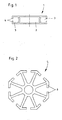
- Fig. 1 shows the cross section of a rectangular profile 1, which has a rectangular hollow chamber 2 in the middle and on both sides thereof groove portions 3.
- the grooves 3 are partially closed, by the legs 4, so that there is an undercut groove, behind which can engage the mushroom-like heads of clamp connectors.
- the elements are tightened, for example by turning an eccentric. They move relative to a body, not shown, which in turn is used in a hollow chamber 2 of a profile and fixed there. In this way, therefore, a profile 1 with its front edge attached to a similar profile 1 and connected to this permanently but releasably.
- FIG. 2 is an octagonal post, in which a plurality of grooves are formed, whose undercut legs are denoted by 6.
- Such octagonal profiles can be used for example as posts.
- Fig. 3 shows a conventional wall.
- the two adjacent side edges 9 are inserted into the grooves 3 each of a profile 1.
- clamp connectors are used, which are then connected to the groove 6 of the profile 5 engage behind this.
- the profiles 1 are practically as long as the side edges 9, while the profile 5 is extended by a length relative to the edge 8, so that the connector 1 can be connected to the profile 5.
- the edge 10 is free. This would now serve the connection to the next wall or between the profiles 1, another edge profile 1 along the edge 10 could be lengthened, for example, also the post element of the adjacent wall.
- an edge profile element which on the one hand has a groove which serves to receive a free edge of a plate element.
- the opposite is a spring element is formed.
- This spring element can be used grooves corresponding posts or bars profiles.
- the edge profile element has an area for connection with another profile element.
- This edge profile element makes it possible to initially form a complete frame of profile elements, so post, locking elements and the edge profile element represent the four edges of a closed rectangle.
- Fig. 4 shows an example of such a wallboard element. Furthermore, the once made wallboard element can be reused again and again, without having to constantly be assembled and disassembled.
- the same Wandbauplatten 1952 can be connected together in the simplest way on site.
- the locking elements of a Wandbauplatten varieties can be connected with their free end edges by means of corresponding terminal connector with the post element of the next wallboard element. Since the edge profile element has a spring, this is automatically inserted into the groove of the post element. In this way, very quickly prefabricated Wandbauplattenimplantation can be assembled into a whole wall. Even a superstructure is easily possible. In the corner can then using appropriate corner profiles or multiple profiles - such as the in Fig. 2 shown - fast wallboard panels are built over the corner. In this way, rooms can be created very easily and very quickly.
- Such novel wall elements can be prefabricated. On site, they are then assembled and assembled to the desired buildings, such as exhibition buildings, etc. It is known to stack such wall elements, for example, with the interposition of cushioning elements and to transport in this way. This has the disadvantage that the wall elements constantly have to be relocated manually, for example, from a stack of storage in a hall on a transport vehicle, at the destination again on a stack and the like. Despite temporary storage of upholstery elements, the edge areas are easily and often damaged. Also, the surface areas can be easily damaged by improper handling or be defaced, so that the wall elements must be replaced.
- the present invention the object of the invention to provide a device for storage and transport of wall components, which is easy to build and easy to handle with little economic effort, and which makes it possible to safely store a number of wall panels and to transport.
- the storage and transport device makes it possible to use the prefabricated Wandbauplatten shame arranged using the recording grooves and spaced from each other and thus to protect against damage during storage and transport.
- the fully assembled device can then be placed in a warehouse or placed on transport vehicles for transport purposes. On-site, the device can be spent with all used Wandbauplatten implantn to the site, so that there removed the Wandbauplattenmaschine and can be used to create the desired wall.
- the storage and transport devices are stackable. Empty storage and transport devices are dismantled so far that they can be easily stored space-saving and possibly also stacked. Using the pallet area, the disassembled devices can also be readily moved singly or in stacks.
- base element and roof element define only two opposite surfaces of the storage and transport device. These do not necessarily have to be arranged at the top and bottom, they can also be arranged left and right.
- one of the frame-forming frame members is formed so as to be usable as a pallet, for example.
- the wallboard elements are practically transversely in the transport device.
- the transport device can also be high in such a case, so that a plurality of wallboard elements with end edges abutting one another or one behind the other are arranged.
- the grooves For the training of the grooves for the wall elements there are different approaches. These may be short or long profile pieces with a U-shaped cross-section, the spaces between pin elements, plate elements, wave profiles or recesses produced by milling, injection molding or other methods in plates or profile pieces. According to the invention, the grooves have on one side a V-shaped feed delta, wherein the feed delta of two adjacent grooves are formed on opposite sides.
- the sides, so the one base plate and a roof plate connecting elements are designed as a frame construction. These can be divisible, hinged or otherwise foldable. Also, base and roof elements can be designed as pure frame structures to save weight.
- a hinged or hinged locking bracket which is pre-set after assembly before the inserted wallboard elements for security purposes.
- the storage and transport device is preferably formed of metal, but may also be wholly or partly made of plastic profiles or other materials, such as wood or the like.
- the storage and transport device according to the invention can be stored to save space even by the dismantling.
- Composite it serves for the insertion of wallboard elements.
- the grooves can in principle be adapted to the cross-sectional contours of the wallboard elements accordingly.
- the Wandbauplattenetti are secured and without mutually damaging each other in the transport device. According to the invention this can be fitted from both sides, with building board elements can be inserted alternately with thick end posts.
- FIGS. 1 to 4 serve to explain belonging to the prior art wallboard, which serves to understand the execution of a storage / transport device according to the invention.
- a storage / transport device 21 comprises a base 22 and a roof 23 and the intermediate side frame 24.
- the base 22 is designed as a pallet 25.
- the wall elements can be used.
- FIGS. 6 and 7 an embodiment for a base or a roof is shown.
- a groove plate 28 is shown on a base frame or a base plate 27 .
- this grooves are introduced for example by milling, in which wallboard or wall elements are inserted. These grooves can be made by milling in plates or generated by the application of strips. Also Leisten publishede, U-profiles or the like are suitable. In this way, the grooves can also be flexibly adapted to Wandbauplattensysteme.
- the grooves on one side have a V-shaped feed delta. In this way, the plates can be easily inserted and the edge profiles with a larger cross-section can be easily positioned there.
- the side frames 24 may be separated from the base plate and the roof member, or are hinged, demountable, telescoping or collapsible.
- An empty storage and transport container can be merged to save space in this way.
- a variety of such containers can be stacked and stored and transported in this way space-saving.
- a built-up storage and transport container is then equipped with construction panels, as for example in Fig. 8 and in an alternative embodiment in FIG Fig. 9 is shown.
- Fig. 8 stand the Wandbauplatten 7 vertically in the storage / transport device 21. These are mutually inserted from both sides into the grooves. Both sides are then closed by a bracket, not shown, to prevent slipping out of the plates. In this way, the plates are safely spaced and can be stored and transported in this way.
- the plates are inserted horizontally in the storage and transport device. It is also possible to use several plate levels one above the other. In the illustrated embodiment according to Fig. 9 two wall panels 7 are abutting horizontally inserted into the device.
Landscapes
- Engineering & Computer Science (AREA)
- Mechanical Engineering (AREA)
- Load-Bearing And Curtain Walls (AREA)
- Packaging Frangible Articles (AREA)
- Pallets (AREA)
- Packaging Of Annular Or Rod-Shaped Articles, Wearing Apparel, Cassettes, Or The Like (AREA)
- Residential Or Office Buildings (AREA)
Description
- Die vorliegende Erfindung betrifft eine Lager und Transportvorrichtung für Wandbauelemente.
- Systeme für den Aufbau von Wänden, insbesondere den mobilen Aufbau, sind insbesondere für den Bereich Messebau bekannt, Stand der Technik und umfangreichem Einsatz. Solche Systeme für Regelsysteme, Messeaufbauten und dergleichen verwenden üblicherweise Klemmverbindersysteme. Zwischen Rahmenteilen wie Pfosten, Regalbrettern und ähnlichen Verbindungsstrukturen werden lösbare Verbinder eingesetzt. So lässt sich eine Schnellverbindetechnik realisieren, so dass ein belastbarer Aufbau erreicht werden kann. Um eine hohe Mobilität erreichen zu können, sind ein schneller Auf-und Abbau angestrebt. Beispielsweise wird ein gattungsgemäßes System in der
EP 1 234 985 B1 offenbart, dort Klemmverbindersystem genannt. Eine Ankereinheit der Verbindungsvorrichtung ist klauenförmig ausgebildet. Sie weist bewegbare Ankerelemente auf, die mit Streben eines Gegenelementes wie einem Pfosten oder dergleichen verbindbar sind. Hierzu werden die Ankerelemente in eine Öffnung des Pfostens eingeführt. Das Festlegen erfolgt dadurch, dass an den Enden der Ankerelemente ausgebildete Klauen den Rand einer Nut oder Öffnung hintergreifen und auf diese Weise die Verbindungsvorrichtung am Pfosten festlegen. Der Antrieb besteht aus einem Getriebe, meistens exzenterbetätigt. - Vergleichbare Systeme sind gezeigt und beschrieben in der
WO 2009/000390 A1 und dergleichen. Es lassen sich mit derartigen Verbindern unter zugehörigen Profilsystemen, beispielsweise auch beschrieben inEP 0 412 339 A2 , beispielsweise Messestände kreieren. - Im Stand der Technik ist es bekannt, dass aus Pfosten und Riegeln, meistens gebildet aus völlig gleichartigen Strangelementen mit Hohlprofilbereichen und hinterschnittenen Nutbereichen, Wände aufgebaut werden. Dies erfolgt dadurch, dass beispielsweise ein Pfosten in seinen Endbereichen mit den Stirnkanten eines Riegels über entsprechende Klemmverbinder verbunden wird. Auf diese Weise entsteht eine Art Rahmen, der offene hinterschnittene Nuten an der Innenwandung zeigt. In diese Nuten lässt sich ohne weiteres ein Ausfachelement, beispielsweise eine Pressspanplatte, eine Glasplatte oder dergleichen einschieben. Es verbleibt jedoch mindestens eine freie Kante, auf die dann beispielsweise wiederum ein Pfosten bzw. ein Riegel aufgesetzt werden muss, der dann mit den angrenzenden Pfosten-/Riegelelementen verbunden werden muss.
- Als Beispiel für entsprechende Strangprofile sind die
Figuren 1 und 2 beigelegt. Eine Zusammenbaumöglichkeit ergibt sich aus derFigur 3 . DieFiguren 1 bis 3 zeigen alle den Stand der Technik. -
Fig. 1 zeigt den Querschnitt eines Rechteckprofils 1, welches in der Mitte eine rechteckige Hohlkammer 2 und an beiden Seiten davon Nutebereiche 3 aufweist. Die Nuten 3 sind teilgeschlossen, und zwar durch die Schenkel 4, so dass sich eine hinterschnittene Nut ergibt, hinter die die pilzartigen Köpfe von Klemmverbindern eingreifen können. Dabei gibt es entweder sogenannte Hammerkopfverbinder, die in eine Einsetzposition in die Nut 3 eingeschoben und dann durch querdrehen hinter die Schenkel 4 gebracht werden, und es gibt sogenannte Klemmverbinder, bei welchen zwei Federelemente die Schenkel 4 hintergreifend in die Nut 3 eingesetzt sind. In beiden Fällen werden die Elemente beispielsweise durch Drehen eines Exzenters angezogen. Dabei bewegen sie sich relativ zu einem nicht gezeigten Körper, der wiederum in einer Hohlkammer 2 eines Profils eingesetzt und dort befestigt ist. Auf diese Weise kann also ein Profil 1 mit seiner Stirnkante an ein gleichartiges Profil 1 angesetzt und mit diesem dauerhaft aber lösbar verbunden werden. - Ein alternatives Profil ist in dem Querschnitt in
Fig. 2 gezeigt, wobei es sich um einen achteckigen Pfosten handelt, bei welchem eine Vielzahl von Nuten gebildet sind, deren hinterschnittene Schenkel mit 6 bezeichnet sind. Derartige Achteckprofile können beispielsweise als Pfosten eingesetzt werden. -
Fig. 3 , ebenfalls Stand der Technik, zeigt eine herkömmliche Wand. Ein Wandelement 7, beispielsweise eine Pressspanplatte, eine Glasscheibe, eine Hartfaserplatte oder dergleichen, die lackiert oder sonst wie dekoriert sein kann, ist mit einer Längskante 8 in die Nut eines Profils 5 eingesetzt. Die beiden daran angrenzenden Seitenkanten 9 sind in die Nuten 3 jeweils eines Profils 1 eingesetzt. In die Hohlkammern 2 der Profile 1 sind Klemmverbinder eingesetzt, die dann die Nut 6 des Profils 5 hintergreifend mit diesen verbunden werden. Wie die Verbindungsstelle 11 zeigt, sind dabei die Profile 1 praktisch so lang wie die Seitenkanten 9, während das Profil 5 um eine Länge gegenüber der Kante 8 verlängert ist, so dass die Verbinder 1 mit dem Profil 5 verbunden werden können. Es ist offensichtlich, dass die Kante 10 freisteht. Diese würde nunmehr dem Anschluss an die nächste Wand dienen können oder zwischen die Profile 1 könnte ein weiteres Kantenprofil 1 entlang der Kante 10 langgesetzt werden, beispielsweise ebenfalls das Pfostenelement der benachbarten Wand. - Es versteht sich von selbst, dass anstelle des Profils 5 an dieser Stelle auch ein weiteres Profil 1 als Pfosten eingesetzt und mit den Riegeln 1 an den Querkanten 9 verbunden werden kann. Dieser aus dem Stand der Technik bekannten Wände werden vor Ort montiert.
- Vom Ablauf her werden also die erforderlichen Pfostenelemente und Riegelelemente vorgefertigt. Die notwendige Anzahl von Verbindern wird bereitgelegt und die notwendige Anzahl von Wandbauplatten wird bereitgelegt. Alle diese Elemente werden separat transportiert. Vor Ort wird dann Wand für Wand aufgebaut. Es zeigt sich, dass damit sehr viel Arbeit vor Ort aufgewandt werden muss. Darüber hinaus sind die Kanten der Wandelemente gefährdet. Das ständige Aufbauen und natürlich nach Abschluss einer Messe beispielsweise erforderliche Wiederabbauen und Transportieren in Einzelteilen ist weder für die Profilelemente noch die Verbinder noch für die Wandbauplatten vorteilhaft. Die Elemente unterliegen einem erheblichen Verschleiß und sind erheblichen Beschädigungsgefahren ausgesetzt.
- Im Stand der Technik ist es neuerdings bekannt, ein Kantenprofilelement einzusetzen, welches einerseits eine Nut aufweist, die zur Aufnahme der einer freien Kante eines Plattenelementes dient. Dem gegenüberliegend wird ein Federelement ausgebildet. Dieses Federelement kann Nuten entsprechender Pfosten- oder Riegel-Profile eingesetzt werden. Darüber hinaus hat das Kantenprofilelement einen Bereich zur Verbindung mit einem weiteren Profilelement.
- Dieses Kantenprofilelement ermöglicht es, zunächst einmal einen vollständigen Rahmen aus Profilelementen zu bilden, also Pfosten-, Riegelelemente und das Kantenprofilelement stellen die vier Kanten eines geschlossenen Rechtecks dar. Zum inneren weisen umlaufend vier Nuten von den Pfosten- und Riegelelementen sowie den Kantenprofilelement. Diese Nuten dienen der Aufnahme einer Wandbauplatte. Da die Elemente, also die Pfosten-, Riegel- und Kantenprofilelemente miteinander verbindbar sind, entsteht auf diese Weise ein vorgefertigtes Wandbauplattenelement. Ein derartiges vorgefertigtes Wandbauplattenelement kann in seiner Gesamtheit transportiert werden, so dass die Wandbauplatte im Kantenbereich nicht mehr Beschädigungen unterliegt.
Fig. 4 zeigt beispielhaft ein derartiges Wandbauplattenelement. Weiterhin kann das einmal gefertigte Wandbauplattenelement immer wiederverwendet werden, ohne dass es ständig zusammengebaut und zerlegt werden muss. Darüber hinaus können gleiche Wandbauplattenelemente vor Ort auf einfachste Weise miteinander verbunden werden. Dabei können die Riegelelemente des einen Wandbauplattenelementes mit ihren freien Stirnkanten mittels entsprechender Klemmverbinder mit dem Pfostenelement des nächsten Wandbauplattenelementes verbunden werden. Da das Kantenprofilelement eine Feder aufweist, setzt sich diese automatisch in die Nut des Pfostenelementes ein. Auf diese Weise können sehr schnell vorgefertigte Wandbauplattenelemente zu einer ganzen Wand zusammengebaut werden. Sogar ein Übereinanderbau ist ohne weiteres möglich. Im Eckbereich können dann unter Verwendung entsprechender Eckprofile oder Mehrfachprofile - wie beispielsweise das inFig. 2 gezeigte - schnell Wandbauplattenelemente über die Ecke gebaut werden. Auf diese Weise lassen sich sehr leicht und sehr schnell Räume erzeugen. - Derartige Neuartige Wandelemente können vorgefertigt werden. Vor Ort werden sie dann zu den gewünschten Bauten, beispielsweise Messebauten usw., zusammen gesetzt und montiert. Es ist bekannt, derartige Wandelemente, beispielsweise unter Zwischenlegung von Polsterelementen zu stapeln und auf diese Weise zu transportieren. Dies hat den Nachteil, dass die Wandelemente ständig wieder manuell verlagert werden müssen, beispielsweise von einem Lagerstapel in einer Halle auf einem Transportfahrzeug, am Bestimmungsort wieder auf einen Stapel und dergleichen. Trotz Zwischenlagerung von Polsterelementen werden die Kantenbereiche leicht und oft beschädigt. Auch können die Flächenbereiche durch eine unsachgemäße Handhabung leicht beschädigt oder verunstaltet werden, sodass die Wandbauelemente ersetzt werden müssen.
- Ausgehend vom vorbeschriebenen Stand der Technik liegt der vorliegenden Erfindung die A u f g a b e zugrunde, eine Vorrichtung zur Lagerung und zum Transport von Wandbauelementen bereitzustellen, die mit geringem wirtschaftlichen Aufwand einfach erstellbar und leicht handhabbar ist, und die es ermöglicht, eine Anzahl von Wandbauplatten sicher zu lagern und zu transportieren.
- Zur technischen Lösung dieser Aufgabe wird mit der Erfindung eine Lager- und Transportvorrichtung mit den Merkmalen des Anspruches 1 vorgeschlagen. Weitere Vorteile und Merkmale der Erfindung ergeben sich aus den Unteransprüchen.
- Die erfindungsgemäße Lager- und Transportvorrichtung ermöglicht es, die vorgefertigten Wandbauplattenelemente unter Verwendung der Aufnahme Nuten geordnet und zueinander beabstandet einzusetzen und somit während Lagerung und Transport vor Beschädigungen zu schützen. Die fertig bestückte Vorrichtung kann dann in einem Lager aufgestellt oder zu Transportzwecken auf Transportfahrzeuge aufgesetzt werden. Vorort kann die Vorrichtung mit allen eingesetzten Wandbauplattenelementen zum Aufstellungsort verbracht werden, sodass dort die Wandbauplattenelemente entnommen und zum Erstellen der gewünschten Wand verwendet werden können. Erfindungsgemäß sind die Lager- und Transportvorrichtungen stapelbar. Leere Lager- und Transportvorrichtungen sind soweit zerlegbar, dass sie ohne weiteres platzsparend und gegebenenfalls ebenfalls gestapelt gelagert werden können. Unter Verwendung des Palettenbereiches lassen sich auch die zerlegten Vorrichtungen ohne weiteres Einzeln oder in Stapeln bewegen.
- Die Begriffe Basiselement und Dachelement definieren lediglich zwei gegenüberliegende Oberflächen der Lager- und Transportvorrichtung. Diese müssen nicht zwingend oben und unten angeordnet sein, sie können auch links und rechts angeordnet sein. In diesem Fall ist eines der einen Boden bildenden Rahmenelemente so ausgebildet, dass es beispielsweise wie eine Palette nutzbar ist. In einem solchen Fall liegen die Wandbauplattenelemente praktisch quer in der Transportvorrichtung. Die Transportvorrichtung kann in einem solchen Fall auch hoch sein, sodass mehrere Wandbauplattenelemente mit Stirnkanten aneinanderstoßend übereinander oder hintereinander angeordnet sind.
- Für die Ausbildung der Aufnahmenuten für die Wandbauelemente gibt es unterschiedliche Lösungsansätze. Dies können kurze oder lange Profilstücke mit U-förmigen Querschnitt sein, die Zwischenräume zwischen Stiftelementen, Plattenelementen, Wellenprofile oder auch durch Fräsung, Spritzgiesen oder sonstige Verfahren hergestellte Vertiefungen in Platten oder Profilstücken. Erfindungsgemäß weisen die Nuten einseitig ein V-förmiges Zuführungsdelta auf, wobei die Zuführungsdelta von zwei benachbarten Nuten an einander gegenüberliegenden Seiten ausgebildet sind.
- Die Seiten, also die eine Basisplatte und eine Dachplatte verbindenden Elemente sind als Rahmenkonstruktion ausgebildet. Diese können teilbar, klappbar oder sonst wie faltbar sein. Auch können Basis und Dachelemente als reine Rahmenkonstruktionen ausgebildet sein, um Gewicht zu sparen.
- An der Seite, von der aus das Lager- und Transportelement vorzugsweise mit Wandbauplattenelementen bestückt wird, ist gemäß der Erfindung vorgesehen, einen schwenkbaren oder klappbaren Sperrbügel einzusetzen, der nach der Bestückung vor die eingeschobenen Wandbauplattenelemente zu Sicherungszwecken vorgesetzt wird.
- Die Lager- und Transportvorrichtung ist vorzugsweise aus Metall gebildet, kann aber auch ganz oder teilweise aus Kunststoffprofilen oder anderen Materialien, wie beispielsweise Holz oder dergleichen gefertigt sein.
- Die erfindungsgemäße Lager- und Transportvorrichtung ist selbst durch die Zerlegbarkeit platzsparend lagerbar. Zusammengesetzt dient sie dem Einschieben von Wandbauplattenelementen. Dabei können die Nuten grundsätzlich den Querschnittskonturen der Wandbauplattenelemente entsprechend angepasst sein. Die Wandbauplattenelemente stehen gesichert und ohne einander gegenseitig beschädigen zu können, in der Transportvorrichtung. Erfindungsgemäß kann diese von beiden Seiten bestückt werden, wobei Bauplattenelemente mit dicken Endpfosten alternierend eingeschoben werden können.
- Die Erfindung ist mit geringem wirtschaftlichem Aufwand herstellbar und dient zur beschädigungsfreien und sicheren Lagerung von Wandbauplattenelement und zu deren Transport zum Bestimmungsort. Vorort können die Vorrichtungen entleert, gegebenenfalls zusammen gelegt und zweckmäßig zwischengelagert werden, bis die Wandbauplattenelemente wieder zum Lager zurücktransportiert werden müssen.
-
Fig. 1 eine Schnittdarstellung durch ein Hohlprofilelement (Stand der Technik); -
Fig. 2 eine Schnittdarstellung durch ein weiteres Profilelement (Stand der Technik); -
Fig. 3 eine schematische Darstellung eines Wandbauelementes nach dem Stand der Technik; -
Fig. 4 eine schematische Draufsicht auf ein Wandbauplattenelement (Stand der Technik); -
Fig. 5 eine schematische perspektivische Darstellung eines Ausführungsbeispiels für eine Lager-/Transportvorrichtung nach der Erfindung; -
Fig. 6 eine Darstellung eines Ausführungsbeispiels für eine Nutplatte; -
Fig. 7 eine Seitenansicht der Nutplatte gemäßFig. 6 ; -
Fig. 8 eine schematische Seitenansicht der Ausführung gemäßFig. 5 , bestückt mit Wandbauplatten und -
Fig. 9 ein alternatives Ausführungsbeispiel mit quer gelagerten Wandbauplatten. - In den Figuren sind gleiche Elemente mit gleichen Bezugszeichen versehen.
- Die
Figuren 1 bis 4 dienen der Erläuterung von zum Stand der Technik gehörenden Wandbauplatten, was dem Verständnis der Ausführung einer erfindungsgemäßen Lager-/Transportvorrichtung dient. - Die in
Fig. 5 gezeigte Ausführungsform einer Lager-/Transportvorrichtung 21 umfasst eine Basis 22 und ein Dach 23 sowie an den dazwischen liegenden Seitenrahmen 24. Im gezeigten Ausführungsbeispiel ist die Basis 22 als Palette 25 ausgeführt. Über die offenen Seiten 26 lassen sich die Wandbauelemente einsetzen. - Gemäß
Figuren 6 und 7 ist ein Ausführungsbeispiel für eine Basis bzw. ein Dach gezeigt. Auf einem Grundrahmen oder einer Grundplatte 27 ist im gezeigten Ausführungsbeispiel eine Nutplatte 28 gezeigt. In diese sind Nuten beispielsweise durch Fräsen eingebracht, in welche Wandbauplatten oder Wandbauelemente einschiebbar sind. Diese Nuten können durch Fräsen in Platten eingebracht werden oder durch das Aufbringen von Leisten erzeugt werden. Auch Leistenstücke, U-Profile oder dergleichen sind geeignet. Auf diese Weise können die Nuten auch flexibel an Wandbauplattensysteme anpassbar sein. Erfindungsgemäß haben die Nuten einseitig ein V-förmiges Zuführungsdelta. Auf diese Weise lassen sich die Platten leicht einschieben und die Randprofile mit größerem Querschnitt können dort leicht positioniert werden. - Die Seitenrahmen 24 können von der Basisplatte und dem Dachelement getrennt werden oder sind denen gegenüber klappbar, zerlegbar, teleskopartig oder zusammenfaltbar. Ein leerer Lager- und Transportbehälter kann auf diese Weise platzsparend zusammengelegt werden. Eine Vielzahl solcher Behälter kann gestapelt und auf diese Weise platzsparend gelagert und transportiert werden.
- Ein aufgebauter Lager- und Transportbehälter wird dann mit Bauplatten bestückt, wie dies beispielsweise in
Fig. 8 und in einer alternativen Ausführungsweise inFig. 9 gezeigt ist. - In dem Ausführungsbeispiel gemäß
Fig. 8 stehen die Wandbauplatten 7 senkrecht in der Lager-/Transportvorrichtung 21. Diese sind von beiden Seiten wechselseitig in die Nuten eingeschoben. Beide Seiten werden anschließend durch einen nicht gezeigten Bügel verschlossen, um ein Herausrutschen der Platten zu verhindern. Auf diese Weise stehen die Platten sicher beabstandet und lassen sich auf diese Weise lagern und transportieren. - Bei dem Ausführungsbeispiel gemäß
Fig. 9 sind die Platten horizontal in die Lager- und Transportvorrichtung eingeschoben. Dabei ist es auch möglich, mehrere Plattenebenen übereinander einzusetzen. Im gezeigten Ausführungsbeispiel gemäßFig. 9 sind zwei Wandbauplatten 7 aneinanderstoßend horizontal in die Vorrichtung eingesetzt. - Die beschriebenen Ausführungsbeispiele dienen nur der Erläuterung und sind nicht beschränkend.
-
- 1
- Hohlprofil
- 2
- Hohlkammer
- 3
- Nut
- 4
- Schenkel
- 5
- Profil
- 6
- Nutschenkel
- 7
- Wandbauplatte
- 8
- Seitenkanten
- 9
- Seitenkanten
- 10
- Seitenkanten
- 11
- Eckbereich
- 15
- Kantenprofil
- 21
- Lager-/Transportvorrichtung
- 22
- Basis
- 23
- Dach
- 24
- Rahmen
- 25
- Palette
- 26
- freie Seite
- 27
- Grundrahmen
- 28
- Nutplatte
- 29
- Nut
Claims (9)
- Lager- und Transportvorrichtung (21) für Wandelemente (7), umfassen ein Basiselement (22), ein Dachelement (23) und wenigstens vier zwischen Basis- und Dachelement angeordneten Pfostenelementen, wobei wenigstens eines der Basis- oder Dachelemente Nuten (29) für das Einschieben von Wandbauelementen (7) aufweist, dadurch gekennzeichnet, dass die Nuten (29) einseitig ein V-förmiges Zuführungsdelta aufweisen, wobei die Zuführungsdelta von zwei benachbarten Nuten (29) an einander gegenüberliegenden Seiten ausgebildet sind.
- Lager-und Transportvorrichtung nach Anspruch 1, dadurch gekennzeichnet, dass das Basiselement (22) als Palettenplatte (25) ausgebildet ist.
- Lager-und Transportvorrichtung nach einem der vorgehenden Ansprüche, dadurch gekennzeichnet, dass diese eine Platte (28) mit eingebrachten Nuten (29) aufweist.
- Lager-und Transportvorrichtung nach Anspruch 3, dadurch gekennzeichnet, dass die Platte (28) eine Vielzahl paralleler Nuten (29) aufweist.
- Lager-und Transportvorrichtung nach einem der vorgehenden Ansprüche, dadurch gekennzeichnet, dass die Pfostenelemente Teil einer Rahmenkonstruktion (24) sind.
- Lager-und Transportvorrichtung nach einem der vorgehenden Ansprüche, dadurch gekennzeichnet, dass das Dachelement (23) als Rahmenelement ausgebildet ist.
- Lager-und Transportvorrichtung nach einem der vorgehenden Ansprüche, dadurch gekennzeichnet, dass diese einen Sperrbügel aufweist.
- Lager- und Transportvorrichtung nach einem der vorgehenden Ansprüche, dadurch gekennzeichnet, dass diese zusammenlegbar ausbildet ist.
- Lager-und Transportvorrichtung nach einem der vorgehenden Ansprüche, dadurch gekennzeichnet, dass diese wenigstens teilweise aus Metall gebildet ist.
Priority Applications (2)
| Application Number | Priority Date | Filing Date | Title |
|---|---|---|---|
| SI201130091T SI2415681T1 (sl) | 2010-08-06 | 2011-03-02 | Skladiščna in transportna priprava |
| PL11001733T PL2415681T3 (pl) | 2010-08-06 | 2011-03-02 | Urządzenie magazynowe i transportowe |
Applications Claiming Priority (1)
| Application Number | Priority Date | Filing Date | Title |
|---|---|---|---|
| DE202010011126U DE202010011126U1 (de) | 2010-08-06 | 2010-08-06 | Lager und Transportvorrichtung |
Publications (2)
| Publication Number | Publication Date |
|---|---|
| EP2415681A1 EP2415681A1 (de) | 2012-02-08 |
| EP2415681B1 true EP2415681B1 (de) | 2013-10-02 |
Family
ID=43299491
Family Applications (1)
| Application Number | Title | Priority Date | Filing Date |
|---|---|---|---|
| EP11001733.2A Not-in-force EP2415681B1 (de) | 2010-08-06 | 2011-03-02 | Lager- und Transportvorrichtung |
Country Status (7)
| Country | Link |
|---|---|
| EP (1) | EP2415681B1 (de) |
| DE (1) | DE202010011126U1 (de) |
| DK (1) | DK2415681T3 (de) |
| ES (1) | ES2435639T3 (de) |
| PL (1) | PL2415681T3 (de) |
| RU (1) | RU2011132787A (de) |
| SI (1) | SI2415681T1 (de) |
Families Citing this family (2)
| Publication number | Priority date | Publication date | Assignee | Title |
|---|---|---|---|---|
| DE202012101930U1 (de) | 2012-05-25 | 2012-07-04 | Hestex Systems B.V. | Bausystem, insbesondere Messebausystem |
| CN114601279B (zh) * | 2022-03-24 | 2025-10-24 | 庄清海 | 一种匾额储存保护系统 |
Family Cites Families (9)
| Publication number | Priority date | Publication date | Assignee | Title |
|---|---|---|---|---|
| DE2234949B2 (de) * | 1972-07-15 | 1976-09-16 | Rheinische Ziehglas AG, 5000 Köln | Stapelbare transportvorrichtung fuer glasscheiben |
| US4445616A (en) * | 1982-06-07 | 1984-05-01 | American Motors Corporation | Cargo container with adjustable retaining mechanism |
| ES2036078T3 (es) | 1989-08-11 | 1993-05-01 | Gerd Und Bernd Vieler Kg. | Bastidor con un acoplador que conecta barras perfiladas. |
| DE9200323U1 (de) * | 1992-01-14 | 1993-01-28 | Lohse, Frank, Dipl.-Ing. (FH), 6330 Wetzlar | Container |
| FR2704214B1 (fr) * | 1993-04-19 | 1995-05-24 | Yves Le Loarer | Container portable destiné au transport de plaques de matériaux fragiles. |
| DE19908824C2 (de) * | 1999-03-01 | 2001-04-26 | Holzindustrie Fuerst Zu Fuerst | Mehrweg-Transportbehälter |
| DE20103064U1 (de) | 2001-02-21 | 2001-06-28 | Hestex Systems B.V., Apeldoorn | Klemmverbindersystem |
| EP2006550A1 (de) | 2007-06-23 | 2008-12-24 | Hestex Systems B.V. | Verbindungsvorrichtung |
| DE202008011823U1 (de) * | 2008-09-05 | 2009-02-19 | Bachmann, Eberhard | Vorrichtung zur Lagerung und/oder zum Transport |
-
2010
- 2010-08-06 DE DE202010011126U patent/DE202010011126U1/de not_active Ceased
-
2011
- 2011-03-02 DK DK11001733.2T patent/DK2415681T3/da active
- 2011-03-02 SI SI201130091T patent/SI2415681T1/sl unknown
- 2011-03-02 PL PL11001733T patent/PL2415681T3/pl unknown
- 2011-03-02 EP EP11001733.2A patent/EP2415681B1/de not_active Not-in-force
- 2011-03-02 ES ES11001733T patent/ES2435639T3/es active Active
- 2011-08-04 RU RU2011132787/12A patent/RU2011132787A/ru not_active Application Discontinuation
Also Published As
| Publication number | Publication date |
|---|---|
| SI2415681T1 (sl) | 2014-02-28 |
| DE202010011126U1 (de) | 2010-12-02 |
| PL2415681T3 (pl) | 2014-03-31 |
| ES2435639T3 (es) | 2013-12-20 |
| EP2415681A1 (de) | 2012-02-08 |
| RU2011132787A (ru) | 2013-02-10 |
| DK2415681T3 (da) | 2013-10-14 |
Similar Documents
| Publication | Publication Date | Title |
|---|---|---|
| DE19932815B4 (de) | Spielfeldbegrenzung | |
| EP2754784B1 (de) | System zur Errichtung einer Wind- und/oder Sichtschutzwand | |
| DE202009007881U1 (de) | Transportpalette zum Transport von Warengut, insbesondere von Solarpaneelen bzw. von Solarmodulen | |
| EP2392742B1 (de) | Kantenprofilelement | |
| AT513227B1 (de) | Wandkonstruktion für den Garten- und Landschaftsbau | |
| EP2415681B1 (de) | Lager- und Transportvorrichtung | |
| DE651562C (de) | Baugeruest, zusammengesetzt aus einer Anzahl von Bauelementen mit durchgehenden Bohrungen zum Durchstecken von Verbindungsmitteln | |
| EP0038086A2 (de) | Bausatz zur Herstellung von Gestellen, Möbeln, Regalen, transportablen Bauwerken und aus diesem Bausatz hergestellter Gegenstand | |
| DE1286721B (de) | Regal | |
| DE9201737U1 (de) | Bauelementensatz zum Aufbau von Böden, Wänden, Decken oder dergleichen und dafür vorgesehenes Profilelement | |
| DE10244244A1 (de) | Modulgerüst | |
| EP1834545A2 (de) | Regalsystem | |
| DE68914795T2 (de) | Verschalung zur Herstellung von Säulen aus Beton oder Zement. | |
| EP0624694A2 (de) | Pyramidenförmiges Dachgerüst, insbesondere für ein Glasdach | |
| DE102012104166B4 (de) | Terrassenmodul einer Holzterrasse | |
| DE2626407A1 (de) | Biegesteife steckverbindung zum verbinden von regal-, geruest-, tribuenen-, treppen- oder dergleichen bauteilen | |
| DE202007011171U1 (de) | Transport- und Lagerpalette | |
| DE2352298C3 (de) | Quaderförmiges Bauelement fur ein Arbeitsgerüst o.dgl | |
| DE202015104127U1 (de) | Modulares Wandelement | |
| AT15685U1 (de) | Hochbeet oder Komposter aus Beton-Einzelelementen | |
| DE202014100432U1 (de) | Transportbehälter | |
| DE844057C (de) | Zusammensetzbare und zerlegbare Schalungen aus vorfabrizierten Elementen fuer den Betonbau | |
| AT206144B (de) | Anlage zur Bildung von Einordnungsfächern, insbesondere zur Einlagerung von Waren | |
| DE2344992A1 (de) | Mittel zur verbindung und herstellung von moebeln, teilen von moebeln, moebelrahmen oder aehnlichem | |
| DE8034252U1 (de) | Glastransport-Gestell |
Legal Events
| Date | Code | Title | Description |
|---|---|---|---|
| AK | Designated contracting states |
Kind code of ref document: A1 Designated state(s): AL AT BE BG CH CY CZ DE DK EE ES FI FR GB GR HR HU IE IS IT LI LT LU LV MC MK MT NL NO PL PT RO RS SE SI SK SM TR |
|
| AX | Request for extension of the european patent |
Extension state: BA ME |
|
| PUAI | Public reference made under article 153(3) epc to a published international application that has entered the european phase |
Free format text: ORIGINAL CODE: 0009012 |
|
| 17P | Request for examination filed |
Effective date: 20120802 |
|
| GRAP | Despatch of communication of intention to grant a patent |
Free format text: ORIGINAL CODE: EPIDOSNIGR1 |
|
| RIC1 | Information provided on ipc code assigned before grant |
Ipc: B65D 85/48 20060101ALI20130523BHEP Ipc: B65D 19/44 20060101AFI20130523BHEP Ipc: B65D 25/10 20060101ALN20130523BHEP |
|
| INTG | Intention to grant announced |
Effective date: 20130611 |
|
| RIN1 | Information on inventor provided before grant (corrected) |
Inventor name: SINT NICOLAAS, ARIE |
|
| GRAS | Grant fee paid |
Free format text: ORIGINAL CODE: EPIDOSNIGR3 |
|
| GRAA | (expected) grant |
Free format text: ORIGINAL CODE: 0009210 |
|
| AK | Designated contracting states |
Kind code of ref document: B1 Designated state(s): AL AT BE BG CH CY CZ DE DK EE ES FI FR GB GR HR HU IE IS IT LI LT LU LV MC MK MT NL NO PL PT RO RS SE SI SK SM TR |
|
| REG | Reference to a national code |
Ref country code: GB Ref legal event code: FG4D Free format text: NOT ENGLISH |
|
| REG | Reference to a national code |
Effective date: 20131010 Ref country code: DK Ref legal event code: T3 |
|
| REG | Reference to a national code |
Ref country code: AT Ref legal event code: REF Ref document number: 634473 Country of ref document: AT Kind code of ref document: T Effective date: 20131015 Ref country code: CH Ref legal event code: NV Representative=s name: E. BLUM AND CO. AG PATENT- UND MARKENANWAELTE , CH Ref country code: CH Ref legal event code: EP |
|
| REG | Reference to a national code |
Ref country code: SE Ref legal event code: TRGR |
|
| REG | Reference to a national code |
Ref country code: IE Ref legal event code: FG4D Free format text: LANGUAGE OF EP DOCUMENT: GERMAN |
|
| REG | Reference to a national code |
Ref country code: NL Ref legal event code: T3 |
|
| REG | Reference to a national code |
Ref country code: DE Ref legal event code: R096 Ref document number: 502011001405 Country of ref document: DE Effective date: 20131128 |
|
| REG | Reference to a national code |
Ref country code: ES Ref legal event code: FG2A Ref document number: 2435639 Country of ref document: ES Kind code of ref document: T3 Effective date: 20131220 |
|
| REG | Reference to a national code |
Ref country code: LT Ref legal event code: MG4D |
|
| REG | Reference to a national code |
Ref country code: HU Ref legal event code: AG4A Ref document number: E018795 Country of ref document: HU |
|
| PG25 | Lapsed in a contracting state [announced via postgrant information from national office to epo] |
Ref country code: NO Free format text: LAPSE BECAUSE OF FAILURE TO SUBMIT A TRANSLATION OF THE DESCRIPTION OR TO PAY THE FEE WITHIN THE PRESCRIBED TIME-LIMIT Effective date: 20140102 Ref country code: IS Free format text: LAPSE BECAUSE OF FAILURE TO SUBMIT A TRANSLATION OF THE DESCRIPTION OR TO PAY THE FEE WITHIN THE PRESCRIBED TIME-LIMIT Effective date: 20140202 Ref country code: LT Free format text: LAPSE BECAUSE OF FAILURE TO SUBMIT A TRANSLATION OF THE DESCRIPTION OR TO PAY THE FEE WITHIN THE PRESCRIBED TIME-LIMIT Effective date: 20131002 Ref country code: FI Free format text: LAPSE BECAUSE OF FAILURE TO SUBMIT A TRANSLATION OF THE DESCRIPTION OR TO PAY THE FEE WITHIN THE PRESCRIBED TIME-LIMIT Effective date: 20131002 Ref country code: HR Free format text: LAPSE BECAUSE OF FAILURE TO SUBMIT A TRANSLATION OF THE DESCRIPTION OR TO PAY THE FEE WITHIN THE PRESCRIBED TIME-LIMIT Effective date: 20131002 |
|
| PG25 | Lapsed in a contracting state [announced via postgrant information from national office to epo] |
Ref country code: CY Free format text: LAPSE BECAUSE OF FAILURE TO SUBMIT A TRANSLATION OF THE DESCRIPTION OR TO PAY THE FEE WITHIN THE PRESCRIBED TIME-LIMIT Effective date: 20131002 Ref country code: RS Free format text: LAPSE BECAUSE OF FAILURE TO SUBMIT A TRANSLATION OF THE DESCRIPTION OR TO PAY THE FEE WITHIN THE PRESCRIBED TIME-LIMIT Effective date: 20131002 Ref country code: LV Free format text: LAPSE BECAUSE OF FAILURE TO SUBMIT A TRANSLATION OF THE DESCRIPTION OR TO PAY THE FEE WITHIN THE PRESCRIBED TIME-LIMIT Effective date: 20131002 |
|
| PG25 | Lapsed in a contracting state [announced via postgrant information from national office to epo] |
Ref country code: PT Free format text: LAPSE BECAUSE OF FAILURE TO SUBMIT A TRANSLATION OF THE DESCRIPTION OR TO PAY THE FEE WITHIN THE PRESCRIBED TIME-LIMIT Effective date: 20140203 |
|
| REG | Reference to a national code |
Ref country code: DE Ref legal event code: R097 Ref document number: 502011001405 Country of ref document: DE |
|
| PG25 | Lapsed in a contracting state [announced via postgrant information from national office to epo] |
Ref country code: EE Free format text: LAPSE BECAUSE OF FAILURE TO SUBMIT A TRANSLATION OF THE DESCRIPTION OR TO PAY THE FEE WITHIN THE PRESCRIBED TIME-LIMIT Effective date: 20131002 |
|
| PLBE | No opposition filed within time limit |
Free format text: ORIGINAL CODE: 0009261 |
|
| STAA | Information on the status of an ep patent application or granted ep patent |
Free format text: STATUS: NO OPPOSITION FILED WITHIN TIME LIMIT |
|
| PG25 | Lapsed in a contracting state [announced via postgrant information from national office to epo] |
Ref country code: SK Free format text: LAPSE BECAUSE OF FAILURE TO SUBMIT A TRANSLATION OF THE DESCRIPTION OR TO PAY THE FEE WITHIN THE PRESCRIBED TIME-LIMIT Effective date: 20131002 Ref country code: RO Free format text: LAPSE BECAUSE OF FAILURE TO SUBMIT A TRANSLATION OF THE DESCRIPTION OR TO PAY THE FEE WITHIN THE PRESCRIBED TIME-LIMIT Effective date: 20131002 |
|
| 26N | No opposition filed |
Effective date: 20140703 |
|
| REG | Reference to a national code |
Ref country code: DE Ref legal event code: R097 Ref document number: 502011001405 Country of ref document: DE Effective date: 20140703 |
|
| PG25 | Lapsed in a contracting state [announced via postgrant information from national office to epo] |
Ref country code: LU Free format text: LAPSE BECAUSE OF FAILURE TO SUBMIT A TRANSLATION OF THE DESCRIPTION OR TO PAY THE FEE WITHIN THE PRESCRIBED TIME-LIMIT Effective date: 20140302 |
|
| REG | Reference to a national code |
Ref country code: IE Ref legal event code: MM4A |
|
| PG25 | Lapsed in a contracting state [announced via postgrant information from national office to epo] |
Ref country code: IE Free format text: LAPSE BECAUSE OF NON-PAYMENT OF DUE FEES Effective date: 20140302 |
|
| PG25 | Lapsed in a contracting state [announced via postgrant information from national office to epo] |
Ref country code: MT Free format text: LAPSE BECAUSE OF FAILURE TO SUBMIT A TRANSLATION OF THE DESCRIPTION OR TO PAY THE FEE WITHIN THE PRESCRIBED TIME-LIMIT Effective date: 20131002 |
|
| REG | Reference to a national code |
Ref country code: FR Ref legal event code: PLFP Year of fee payment: 6 |
|
| PG25 | Lapsed in a contracting state [announced via postgrant information from national office to epo] |
Ref country code: SM Free format text: LAPSE BECAUSE OF FAILURE TO SUBMIT A TRANSLATION OF THE DESCRIPTION OR TO PAY THE FEE WITHIN THE PRESCRIBED TIME-LIMIT Effective date: 20131002 Ref country code: NO Free format text: LAPSE BECAUSE OF FAILURE TO SUBMIT A TRANSLATION OF THE DESCRIPTION OR TO PAY THE FEE WITHIN THE PRESCRIBED TIME-LIMIT Effective date: 20140101 |
|
| PG25 | Lapsed in a contracting state [announced via postgrant information from national office to epo] |
Ref country code: MC Free format text: LAPSE BECAUSE OF FAILURE TO SUBMIT A TRANSLATION OF THE DESCRIPTION OR TO PAY THE FEE WITHIN THE PRESCRIBED TIME-LIMIT Effective date: 20131002 |
|
| PG25 | Lapsed in a contracting state [announced via postgrant information from national office to epo] |
Ref country code: BG Free format text: LAPSE BECAUSE OF FAILURE TO SUBMIT A TRANSLATION OF THE DESCRIPTION OR TO PAY THE FEE WITHIN THE PRESCRIBED TIME-LIMIT Effective date: 20131002 Ref country code: GR Free format text: LAPSE BECAUSE OF FAILURE TO SUBMIT A TRANSLATION OF THE DESCRIPTION OR TO PAY THE FEE WITHIN THE PRESCRIBED TIME-LIMIT Effective date: 20140103 |
|
| PG25 | Lapsed in a contracting state [announced via postgrant information from national office to epo] |
Ref country code: TR Free format text: LAPSE BECAUSE OF FAILURE TO SUBMIT A TRANSLATION OF THE DESCRIPTION OR TO PAY THE FEE WITHIN THE PRESCRIBED TIME-LIMIT Effective date: 20131002 |
|
| REG | Reference to a national code |
Ref country code: FR Ref legal event code: PLFP Year of fee payment: 7 |
|
| PGFP | Annual fee paid to national office [announced via postgrant information from national office to epo] |
Ref country code: SE Payment date: 20170321 Year of fee payment: 7 |
|
| PGFP | Annual fee paid to national office [announced via postgrant information from national office to epo] |
Ref country code: SI Payment date: 20170302 Year of fee payment: 7 Ref country code: PL Payment date: 20170302 Year of fee payment: 7 Ref country code: HU Payment date: 20170316 Year of fee payment: 7 Ref country code: DK Payment date: 20170321 Year of fee payment: 7 |
|
| PGFP | Annual fee paid to national office [announced via postgrant information from national office to epo] |
Ref country code: CZ Payment date: 20170412 Year of fee payment: 7 |
|
| PGFP | Annual fee paid to national office [announced via postgrant information from national office to epo] |
Ref country code: IT Payment date: 20170323 Year of fee payment: 7 |
|
| REG | Reference to a national code |
Ref country code: DE Ref legal event code: R082 Ref document number: 502011001405 Country of ref document: DE Representative=s name: RAUSCH WANISCHECK-BERGMANN BRINKMANN PARTNERSC, DE |
|
| REG | Reference to a national code |
Ref country code: FR Ref legal event code: PLFP Year of fee payment: 8 |
|
| PGFP | Annual fee paid to national office [announced via postgrant information from national office to epo] |
Ref country code: NL Payment date: 20180329 Year of fee payment: 8 Ref country code: GB Payment date: 20180329 Year of fee payment: 8 |
|
| PGFP | Annual fee paid to national office [announced via postgrant information from national office to epo] |
Ref country code: AT Payment date: 20180403 Year of fee payment: 8 Ref country code: FR Payment date: 20180329 Year of fee payment: 8 Ref country code: BE Payment date: 20180329 Year of fee payment: 8 |
|
| PG25 | Lapsed in a contracting state [announced via postgrant information from national office to epo] |
Ref country code: MK Free format text: LAPSE BECAUSE OF FAILURE TO SUBMIT A TRANSLATION OF THE DESCRIPTION OR TO PAY THE FEE WITHIN THE PRESCRIBED TIME-LIMIT Effective date: 20131002 |
|
| PGFP | Annual fee paid to national office [announced via postgrant information from national office to epo] |
Ref country code: CH Payment date: 20180419 Year of fee payment: 8 Ref country code: ES Payment date: 20180430 Year of fee payment: 8 Ref country code: DE Payment date: 20180528 Year of fee payment: 8 |
|
| REG | Reference to a national code |
Ref country code: DK Ref legal event code: EBP Effective date: 20180331 |
|
| PG25 | Lapsed in a contracting state [announced via postgrant information from national office to epo] |
Ref country code: AL Free format text: LAPSE BECAUSE OF FAILURE TO SUBMIT A TRANSLATION OF THE DESCRIPTION OR TO PAY THE FEE WITHIN THE PRESCRIBED TIME-LIMIT Effective date: 20131002 Ref country code: SE Free format text: LAPSE BECAUSE OF NON-PAYMENT OF DUE FEES Effective date: 20180303 |
|
| PG25 | Lapsed in a contracting state [announced via postgrant information from national office to epo] |
Ref country code: CZ Free format text: LAPSE BECAUSE OF NON-PAYMENT OF DUE FEES Effective date: 20180302 Ref country code: SI Free format text: LAPSE BECAUSE OF NON-PAYMENT OF DUE FEES Effective date: 20180303 |
|
| REG | Reference to a national code |
Ref country code: SI Ref legal event code: KO00 Effective date: 20181008 |
|
| PG25 | Lapsed in a contracting state [announced via postgrant information from national office to epo] |
Ref country code: HU Free format text: LAPSE BECAUSE OF NON-PAYMENT OF DUE FEES Effective date: 20180303 |
|
| PG25 | Lapsed in a contracting state [announced via postgrant information from national office to epo] |
Ref country code: IT Free format text: LAPSE BECAUSE OF NON-PAYMENT OF DUE FEES Effective date: 20180302 |
|
| PG25 | Lapsed in a contracting state [announced via postgrant information from national office to epo] |
Ref country code: DK Free format text: LAPSE BECAUSE OF NON-PAYMENT OF DUE FEES Effective date: 20180331 |
|
| REG | Reference to a national code |
Ref country code: DE Ref legal event code: R119 Ref document number: 502011001405 Country of ref document: DE |
|
| REG | Reference to a national code |
Ref country code: CH Ref legal event code: PL |
|
| REG | Reference to a national code |
Ref country code: NL Ref legal event code: MM Effective date: 20190401 |
|
| REG | Reference to a national code |
Ref country code: AT Ref legal event code: MM01 Ref document number: 634473 Country of ref document: AT Kind code of ref document: T Effective date: 20190302 |
|
| GBPC | Gb: european patent ceased through non-payment of renewal fee |
Effective date: 20190302 |
|
| PG25 | Lapsed in a contracting state [announced via postgrant information from national office to epo] |
Ref country code: PL Free format text: LAPSE BECAUSE OF NON-PAYMENT OF DUE FEES Effective date: 20180302 |
|
| REG | Reference to a national code |
Ref country code: BE Ref legal event code: MM Effective date: 20190331 |
|
| PG25 | Lapsed in a contracting state [announced via postgrant information from national office to epo] |
Ref country code: NL Free format text: LAPSE BECAUSE OF NON-PAYMENT OF DUE FEES Effective date: 20190401 Ref country code: CH Free format text: LAPSE BECAUSE OF NON-PAYMENT OF DUE FEES Effective date: 20190331 Ref country code: LI Free format text: LAPSE BECAUSE OF NON-PAYMENT OF DUE FEES Effective date: 20190331 Ref country code: AT Free format text: LAPSE BECAUSE OF NON-PAYMENT OF DUE FEES Effective date: 20190302 Ref country code: GB Free format text: LAPSE BECAUSE OF NON-PAYMENT OF DUE FEES Effective date: 20190302 Ref country code: DE Free format text: LAPSE BECAUSE OF NON-PAYMENT OF DUE FEES Effective date: 20191001 |
|
| PG25 | Lapsed in a contracting state [announced via postgrant information from national office to epo] |
Ref country code: FR Free format text: LAPSE BECAUSE OF NON-PAYMENT OF DUE FEES Effective date: 20190331 Ref country code: BE Free format text: LAPSE BECAUSE OF NON-PAYMENT OF DUE FEES Effective date: 20190331 |
|
| REG | Reference to a national code |
Ref country code: ES Ref legal event code: FD2A Effective date: 20200724 |
|
| PG25 | Lapsed in a contracting state [announced via postgrant information from national office to epo] |
Ref country code: ES Free format text: LAPSE BECAUSE OF NON-PAYMENT OF DUE FEES Effective date: 20190303 |