EP2413070B1 - Automatic ice maker - Google Patents
Automatic ice maker Download PDFInfo
- Publication number
- EP2413070B1 EP2413070B1 EP09842334.6A EP09842334A EP2413070B1 EP 2413070 B1 EP2413070 B1 EP 2413070B1 EP 09842334 A EP09842334 A EP 09842334A EP 2413070 B1 EP2413070 B1 EP 2413070B1
- Authority
- EP
- European Patent Office
- Prior art keywords
- water
- ice making
- time period
- deicing
- feeding
- Prior art date
- Legal status (The legal status is an assumption and is not a legal conclusion. Google has not performed a legal analysis and makes no representation as to the accuracy of the status listed.)
- Active
Links
Images


Classifications
-
- F—MECHANICAL ENGINEERING; LIGHTING; HEATING; WEAPONS; BLASTING
- F25—REFRIGERATION OR COOLING; COMBINED HEATING AND REFRIGERATION SYSTEMS; HEAT PUMP SYSTEMS; MANUFACTURE OR STORAGE OF ICE; LIQUEFACTION SOLIDIFICATION OF GASES
- F25C—PRODUCING, WORKING OR HANDLING ICE
- F25C1/00—Producing ice
- F25C1/12—Producing ice by freezing water on cooled surfaces, e.g. to form slabs
-
- F—MECHANICAL ENGINEERING; LIGHTING; HEATING; WEAPONS; BLASTING
- F25—REFRIGERATION OR COOLING; COMBINED HEATING AND REFRIGERATION SYSTEMS; HEAT PUMP SYSTEMS; MANUFACTURE OR STORAGE OF ICE; LIQUEFACTION SOLIDIFICATION OF GASES
- F25C—PRODUCING, WORKING OR HANDLING ICE
- F25C2400/00—Auxiliary features or devices for producing, working or handling ice
- F25C2400/14—Water supply
-
- F—MECHANICAL ENGINEERING; LIGHTING; HEATING; WEAPONS; BLASTING
- F25—REFRIGERATION OR COOLING; COMBINED HEATING AND REFRIGERATION SYSTEMS; HEAT PUMP SYSTEMS; MANUFACTURE OR STORAGE OF ICE; LIQUEFACTION SOLIDIFICATION OF GASES
- F25C—PRODUCING, WORKING OR HANDLING ICE
- F25C2600/00—Control issues
- F25C2600/04—Control means
-
- F—MECHANICAL ENGINEERING; LIGHTING; HEATING; WEAPONS; BLASTING
- F25—REFRIGERATION OR COOLING; COMBINED HEATING AND REFRIGERATION SYSTEMS; HEAT PUMP SYSTEMS; MANUFACTURE OR STORAGE OF ICE; LIQUEFACTION SOLIDIFICATION OF GASES
- F25C—PRODUCING, WORKING OR HANDLING ICE
- F25C2700/00—Sensing or detecting of parameters; Sensors therefor
- F25C2700/04—Level of water
-
- F—MECHANICAL ENGINEERING; LIGHTING; HEATING; WEAPONS; BLASTING
- F25—REFRIGERATION OR COOLING; COMBINED HEATING AND REFRIGERATION SYSTEMS; HEAT PUMP SYSTEMS; MANUFACTURE OR STORAGE OF ICE; LIQUEFACTION SOLIDIFICATION OF GASES
- F25C—PRODUCING, WORKING OR HANDLING ICE
- F25C2700/00—Sensing or detecting of parameters; Sensors therefor
- F25C2700/14—Temperature of water
-
- F—MECHANICAL ENGINEERING; LIGHTING; HEATING; WEAPONS; BLASTING
- F25—REFRIGERATION OR COOLING; COMBINED HEATING AND REFRIGERATION SYSTEMS; HEAT PUMP SYSTEMS; MANUFACTURE OR STORAGE OF ICE; LIQUEFACTION SOLIDIFICATION OF GASES
- F25D—REFRIGERATORS; COLD ROOMS; ICE-BOXES; COOLING OR FREEZING APPARATUS NOT OTHERWISE PROVIDED FOR
- F25D2700/00—Means for sensing or measuring; Sensors therefor
- F25D2700/10—Sensors measuring the temperature of the evaporator
Definitions
- the present invention relates to an automatic ice making machine designed in such a manner that, in ice making operation, a refrigerant is supplied to an evaporator and also ice making water is supplied from an ice making water tank to an ice making unit to produce ice in the ice making unit, and makeup water is additionally supplied from an external water source via a water feeding means to an ice making water tank having a reduced amount of ice making water storage.
- a flow-down type automatic ice making machine As an automatic ice making machine automatically producing a large amount of ice blocks, a flow-down type automatic ice making machine is known, for example, in which a vertically installed ice making unit is provided with an evaporation tube that is led out of a refrigeration system, and ice making water is spray supplied to the ice making unit that is cooled by this evaporation tube to produce ice blocks, and in which, in deicing operation, ice blocks are separated from the ice making unit to fall down and release.
- This automatic ice making machine is equipped with an ice making water tank to store a required amount of ice making water and is configured to, in ice making operation, pump the ice making water in the ice making water tank with an ice making water pump to supply it to the ice making unit, and to collect ice making water failed to freeze into the ice making water tank and then send it again towards the ice making unit.
- deicing water is spray supplied to a back face of the ice making unit to promote melting a frozen face with ice blocks and also the deicing water is collected into the ice making water tank, and this is used as ice making water in ice making operation for the next time.
- the ice making water tank needs a capacity capable of storing at least an amount of ice making water for one cycle of ice making operation (hereinafter, referred to as a necessary amount of ice making water), which has been a factor causing upsizing of the ice making water tank.
- an automatic ice making machine in which an ice making water tank having a capacity less than the necessary amount of ice making water is employed and, in a case where ice making water in the ice making water tank is lacking during ice making operation, water at normal temperature is additionally supplied from an external water source to the ice making water tank via a water feeding means as makeup water.
- a float switch is equipped in the ice making water tank, and when the float switch detects a lower limit water level of ice making water during ice making operation, supply of makeup water is started by the water feeding means. Then, when the float switch detects an upper limit water level of ice making water, the water feeding means is designed to stop the supply of makeup water. This avoids upsizing of the ice making water tank to allow the entire size of the ice making machine to be compact and also to reduce the deicing time period (refer to Patent Document 1).
- Patent Document 1 Japanese Laid-Open Patent [Kokai] Publication No. Hei 6-74626 .
- US 5 291 747 A describes an electric control apparatus for an ice making machine including an initial water supply cycle control device for opening a water valve for a predetermined time, and a water level sensor mounted within a water tank for detecting whether or not a level of water in the water tank is more than a predetermined level.
- a first check-up device is provided for permitting operation of a defrost/water supply cycle and an ice making cycle when the level of water in the water tank exceeds the predetermined level after an initial water supply cycle is conducted under control of an initial water supply control device.
- a second check-up device permits operation of the ice making cycle when the level of water in the water tank exceeds the predetermined level after the defrost/water supply cycle, and repeats operation at the initial water supply cycle when the level of water in the water tank is less than the predetermined level after the defrost/water supply cycle.
- the amount of makeup water to be supplied by one cycle of water feeding is defined as a constant amount between the lower limit water level and the upper limit water level detected by the float switch.
- the temperature of makeup water is high as in summer, for example, the temperature of ice making water in the ice making water tank rises due to the makeup water supplied to the ice making water tank, and when the ice making water with rising temperature is supplied to the ice making unit, ice blocks under production in the ice making unit are melted by the ice making water, and the melted water ends up being collected into the ice making water tank together with the ice making water.
- the melted water is stored in the ice making water tank, so that the water level of the ice making water in the ice making water tank reaches the upper limit water level in a short period of time, and the amount of makeup water to be substantially supplied from the water feeding means for one cycle of water feeding becomes less.
- the overall amount of fed water is lacking, which has been a cause of production of ice blocks smaller in size at the time of ice making completion.
- the temperature of makeup water when the temperature of makeup water is low as in winter, for example, the temperature rise of the ice making water in the ice making water tank is suppressed and a slight amount of the ice blocks in the ice making unit is melted by the ice making water. Therefore, the water level of the ice making water in the ice making water tank rises slowly for the melted water collected less, and the amount of the makeup water to be substantially supplied from the water feeding means becomes more compared to a case of makeup water at high temperature. If such water feeding is carried out a plurality of times, then the overall amount of fed water becomes excessive, which can be a cause of production of huge ice blocks in the ice making unit at the time of ice making completion. Then, the production of huge ice blocks has sometimes caused deicing fault, or the huge ice blocks have sometimes caused deformation or damage in the ice making unit or the like.
- the present invention is proposed to solve them suitably, and it is an object of the present invention to provide an automatic ice making machine that is designed to modify an amount of water feeding depending on a temperature of makeup water.
- an automatic ice making machine having an ice making unit to which ice making water is supplied while being cooled by an evaporator in ice making operation to produce ice and to which deicing water is supplied from an external water source while being heated by the evaporator in deicing operation to separate the ice, and an ice making water tank which is capable of storing ice making water to be supplied to the ice making unit in ice making operation and in which ice making water having flown down the ice making unit is collected, includes:
- an automatic ice making machine having an ice making unit to which ice making water is supplied while being cooled by an evaporator in ice making operation to produce ice, and an ice making water tank which is capable of storing ice making water to be supplied to the ice making unit in ice making operation, in which ice making water having flown down the ice making unit is collected, and to which ice making water is supplied from an external water source before ice making operation is started, includes:
- makeup water is supplied in the feeding amount of water at high temperature, which is more than the feeding amount of water at low temperature, at the time of additional supply of makeup water in ice making operation, so that it is possible to prevent a decrease in ice making capacity due to lack in water feeding and to produce ice in an appropriate size.
- makeup water is additionally supplied in the feeding amount of water at low temperature, which is less compared to the case of high temperature, so that it is possible to prevent deicing abnormity and deformation, damage, or the like in the ice making unit due to excessive water feeding.
- the amount of feeding water is modified based on the reference temperature reaching time period that is varied depending on the temperature of the ice making water from an external water source identical to that of the makeup water, so that water feeding can be carried out in the feeding amount of water precisely reflecting the temperature of makeup water and it is possible to securely prevent lack in water feeding and excessive water feeding.
- the amount of feeding water is designed to be modified depending on the temperature of makeup water, so that it is possible to prevent a decrease in ice making capacity due to lack in an amount of feeding water and occurrence of deicing fault or the like due to an excessive amount of feeding water.
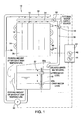
- an automatic ice making machine 10 is a so-called flow-down type automatic ice making machine and is equipped with an ice making unit 16 provided with an evaporation tube (evaporator) 14 led out of a refrigeration system (not shown) between a pair of ice making plates 12, 12 disposed facing each other (only one of them is shown in Fig. 1 ) and capable of production of ice blocks (ice), and an ice making water tank 18 provided below the ice making unit 16 and capable of storing ice making water.
- evaporation tube evaporator
- a refrigerant is designed to be supplied to the evaporation tube 14 from the refrigeration system in ice making operation to cool the ice making unit 16, and also a hot gas is designed to be supplied thereto from the refrigeration system in deicing operation to heat the ice making unit 16.
- the evaporation tube 14 is equipped with a temperature gauge 20 on an exit side of the ice making unit 16 to measure the temperature of the refrigerant heat exchanged with the ice making unit 16 by communicating through the evaporation tube 14 or the hot gas.
- the ice making water tank 18 is equipped with a float switch 22 and is designed to be capable of detecting the water level of ice making water in the ice making water tank 18 by allowing a float 22a of the float switch 22 to go up and down in accordance with the water level of ice making water.
- the capacity of the ice making water tank 18 is set to be less than the necessary amount of ice making water required to produce complete ice in the ice making unit 16 in ice making operation for one cycle (for example, set to be 1/2 to 1/3 of the necessary amount of ice making water). Accordingly, when the ice making water in the ice making water tank 18 is reduced to a predetermined amount in ice making operation, water at normal temperature is designed to be additionally supplied from an external water supply source (external water source) via a water feeding tube 38 described later as makeup water. The additional supply of makeup water carried out in ice making operation is performed a plurality of times (for example, two to three times).
- a lower water level and an upper water level above the lower water level are set as water levels of ice making water, and when the water level of ice making water is at the lower water level or the upper water level, the float switch 22 is designed to send a detection signal thereof to a control means (described later) 24.
- An ice guiding plate 26 is equipped between the ice making unit 16 and the ice making water tank 18 and is designed to guide ice blocks fallen down from the ice making unit 16 with the ice guiding plate 26 in deicing operation to release them to an ice storage, not shown.
- a plurality of return holes (not shown) are opened, and ice making water that has been supplied to the ice making unit 16 and has failed to freeze (unfrozen water) is designed to be collected into the ice making water tank 18 via the return holes. Deicing water that has been supplied to the ice making unit 16 in deicing operation is also collected into the ice making water tank 18 via the return holes to be used as ice making water in ice making operation for the next time.
- An ice making water supply tube 28 is led out of a bottom portion of the ice making water tank 18, and in the middle of the supply tube 28, an ice making water pump 30 is equipped to pump ice making water in the ice making water tank 18 to the ice making unit 16.
- the ice making water supply tube 28 is connected to an ice making water spray (ice making water supply means) 32 that extends above the ice making unit 16, and ice making water is designed to be spray supplied to the ice making unit 16 via the ice making water spray 32.
- a deicing water spray (deicing water supply means) 34 is provided to supply deicing water between the ice making plates 12, 12.
- This deicing water spray 34 is connected to an external water supply source, and water at normal temperature is supplied between the ice making plates 12, 12 via the deicing water spray 34 as deicing water.
- the deicing water spray 34 is equipped with a deicing water valve 36, and by opening and closing the deicing water valve 36, the supply of deicing water from the deicing water spray 34 is designed to be controllable. The opening and closing control of this deicing water valve 36 is carried out by the control means 24.
- the water feeding tube 38 is led out of the external water supply source identical to that of the deicing water spray 34, and an open end of the water feeding tube 38 is opened in the upper inside of the ice making water tank 18.
- makeup water is configured to be supplied to the ice making water tank 18 via the water feeding tube 38.
- This water feeding tube 38 is equipped with a water feeding valve (water feeding means) 40, and by opening and closing the water feeding valve 40, water feeding to the ice making water tank 18 is controlled. The opening and closing control of this water feeding valve 40 is carried out by the control means 24.
- the control means 24 is configured to control overall operation of the automatic ice making machine 10, and also to control the opening and closing of the water feeding valve 40 in a method of water feeding (hereinafter, referred to as a water feeding mode) determined based on the time period of completing deicing operation immediately before the ice making operation in ice making operation.
- the control means 24 is equipped with a deicing timer 42 to keep time of a deicing completion time period T 1 from the start of deicing operation to separation of ice produced in the ice making unit 16 and a delay timer 44 to keep time of a first delay time period that delays timing of stopping water feeding.
- a deicing water longest supply time period U 1 which is a longest time period of deicing water supply to the ice making unit 16 in deicing operation is preset as a deicing base elapsed time period.
- the deicing timer 42 is designed to be activated concurrently with start of deicing operation, and to be stopped when a measured temperature of the temperature gauge 20 (temperature of the hot gas) reaches a deicing completion temperature (for example, approximately 9°C) to keep time of the deicing completion time period T 1 .
- a deicing completion temperature for example, approximately 9°C
- the deicing completion time period T 1 is varied based on the temperature of deicing water, and thus by keeping time of the deicing completion time period T 1 , the temperature of makeup water can be figured out indirectly that is supplied from the water source same as that of the deicing water.
- the deicing water longest supply time period U 1 is preset in the control means 24 to limit the amount of deicing water supply from the perspective of energy saving or the like. Accordingly, when the deicing water longest supply time period U 1 has elapsed in deicing operation, deicing water is not supplied in deicing operation thereafter to carry out deicing only with the hot gas.
- the deicing water longest supply time period U 1 refers to the time period required to completely separate the ice blocks produced in the ice making unit 16.
- the deicing water longest supply time period U 1 is approximately six minutes.
- the control means 24 determines high-low of the temperature of deicing water relative to the base temperature by comparing/determining the deicing completion time period T 1 and the deicing water longest supply time period U 1 , which enables to indirectly figure out the temperature of makeup water supplied from the external water supply source identical to that of the deicing water.
- the control means 24 determines the amount of feeding water to be the feeding amount of water at low temperature and controls the water feeding valve 40 so as to carry out water feeding in the feeding amount of water at low temperature in ice making operation for the next time (hereinafter, referred to as a low temperature mode).
- the control means 24 determines the amount of feeding water to be the feeding amount of water at high temperature, which is more than the feeding amount of water at low temperature, and controls the water feeding valve 40 so as to carry out water feeding in the feeding amount of water at high temperature in ice making operation for the next time (hereinafter, referred to as a high temperature mode).
- the base temperature of deicing water is set for each model of the automatic ice making machine 10, and the deicing water longest supply time period U 1 is determined in accordance with the set value of the base temperature.
- the control means 24 is designed to open the water feeding valve 40 after the water level of ice making water in the ice making water tank 18 reaches the lower water level, and then to close the water feeding valve 40 when the water level of the ice making water reaches the upper water level. That is, the feeding amount of water at low temperature becomes the amount of feeding water by which the water level of ice making water in the ice making water tank 18 reaches the upper water level from the lower water level (refer to Fig. 2 ).
- the control means 24 opens the water feeding valve 40 after the water level of ice making water in the ice making water tank 18 reaches the lower water level, and then opens the water feeding valve 40 after the water level of the ice making water reaches the upper water level further until the first delay time period elapses. That is, suppose the water level of ice making water at the time when the first delay time period has elapsed is set as a delayed upper water level, the feeding amount of water at high temperature becomes the amount of feeding water by which the water level of ice making water reaches the delayed upper water level from the lower water level (refer to Fig. 2 ).
- the control means 24 determines the amount of feeding water in ice making operation based on the deicing completion time period T 1 in deicing operation, so that the control means 24 cannot determine the amount of feeding water in the first ice making operation without going through deicing operation.
- the control means 24 is supposed to be preset so that the amount of feeding water is, for example, the feeding amount of water at low temperature.
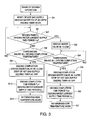
- the control means 24 allows a hot gas to be supplied to the evaporation tube 14 and also the deicing water valve 36 to be opened, and thus the deicing water is supplied between the ice making plates 12, 12 from the external water supply source via the deicing water spray 34.
- the deicing timer 42 built in the control means 24 is activated to start keeping time of the deicing completion time period T 1 (Step S1).
- the ice making unit 16 is heated by the hot gas and the deicing water to start melting ice blocks gradually on the ice making plate 12.
- the deicing operation progresses, the ice blocks are detached and fall down from the ice making plate 12 to be released to the ice storage via the ice guiding plate 26.
- control means 24 determines whether or not the time measured by the deicing timer 42 is equal to or greater than the deicing water longest supply time period U 1 (Step S2). In a case where the time measured by the deicing timer 42 is equal to or greater than the deicing water longest supply time period U 1 (Yes in Step S2), the control means 24 closes the deicing water valve 36 to stop supply of deicing water (Step S3). That is, supply of deicing water more than that is stopped to suppress the amount of deicing water consumption and to suppress the running cost. Deicing operation thereafter is carried out only by heating the ice making unit 16 with the hot gas.
- the control means 24 determines whether or not the temperature measured by the temperature gauge 20 reaches the deicing completion temperature (Step S4), and when the temperature measured by the temperature gauge 20 reaches the deicing completion temperature (Yes in Step S4), the control means 24 finishes the deicing operation and also stops the deicing timer 42 (Step S5). Then, the control means 24 compares the deicing completion time period T 1 and the deicing water longest supply time period U 1 , resulting in the deicing completion time period T 1 being equal to or greater than the deicing water longest supply U 1 (Step S6), so that the water feeding mode is determined to be in the low temperature mode (Step S7). That is, since the temperature of deicing water (makeup water) is lower than the base temperature, the control means 24 determines to supply makeup water in the feeding amount of water at low temperature at the time of water feeding in ice making operation for the next time.
- Step S8 determines whether or not the temperature measured by the temperature gauge 20 reaches the deicing completion temperature. Then, when the temperature measured by the temperature gauge 20 reaches the deicing completion temperature (Yes in Step S8), the control means 24 finishes the deicing operation and also stops the deicing timer 42 (Step S9).
- the control means 24 compares the deicing completion time period T 1 and the deicing water longest supply time period U 1 , resulting in the deicing completion time period T 1 being shorter than the deicing water longest supply U 1 (Step S10), so that the water feeding mode is determined to be in the high temperature mode (Step S11). That is, since the temperature of deicing water (makeup water) is high, the control means 24 determines to supply makeup water in the feeding amount of water at high temperature at the time of water feeding in ice making operation for the next time.
- Step S1 an operation method in ice making operation is described.
- the control means 24 allows a refrigerant to be supplied to the evaporation tube 14 and also activates the ice making water pump 30 to allow ice making water to be circulatively supplied to the ice making unit 16 (Step S1).
- Step S3 the control means 24 opens the water feeding valve 40 to start additional supply of makeup water to the ice making water tank 18 (Step S3).
- the ice making water pump 30 is activated also at the time of water feeding and ice making water in the ice making water tank 18 continues to be supplied to the ice making unit 16, while the amount of feeding water from the water feeding tube 38 is set to be more than the amount of ice making water supply to the ice making unit 16, and thus the water level of ice making water in the ice making water tank 18 starts rising.
- Step S4 when the water level of ice making water in the ice making water tank 18 reaches the upper water level (Yes in Step S4), the float switch 22 detects that to send a detection signal to the control means 24. Then, the control means 24 closes the water feeding valve 40 to stop supply of makeup water. That is, in the low temperature mode, makeup water is supplied in the feeding amount of water at low temperature from the lower water level to the upper water level of the ice making water tank 18 at the time of water feeding (refer to Fig. 2 ). In ice making operation thereafter, every time the ice making water in the ice making water tank 18 is at the lower water level, water feeding in the low temperature mode is repeated. Then, ice blocks in predetermined dimensions are produced on the ice making plate 12, and when the temperature measured by the temperature gauge 20 becomes the ice making completion temperature, the control means 24 finishes the ice making operation to shift it to deicing operation.
- Step S1 a description is given to an operation method in the high temperature mode, which is the case where the temperature of deicing water (makeup water) is higher than the base temperature, with reference to the flowchart in Fig. 5 .
- the control means 24 allows a refrigerant to be supplied to the evaporation tube 14 and also activates the ice making water pump 30 to allow ice making water to be circulatively supplied to the ice making unit 16 (Step S1).
- Step S3 the control means 24 opens the water feeding valve 40 to start supply of makeup water to the ice making water tank 18. Then, the water level of ice making water in the ice making water tank 18 starts rising.
- Step S5 When the water level of ice making water in the ice making water tank 18 reaches the upper water level (Yes in Step S4), the float switch 22 detects that and the control means 24 allows the delay timer 44 to be activated (Step S5). That is, even when the water level of ice making water in the ice making water tank 18 reaches the upper water level, water feeding is carried out without stopping. Then, when the delay timer 44 keeps time of the first delay time period (for example, three seconds) (Yes in Step S6), the control means 24 closes the water feeding valve 40 to stop water feeding. At this time, the water level of ice making water in the ice making water tank 18 has reached the delayed upper water level.
- the delay timer 44 keeps time of the first delay time period (for example, three seconds)
- the automatic ice making machine 10 of Embodiment 1 by allowing the timing of stopping water feeding to be delayed by the first delay time period in the high temperature mode, the water feeding time period is extended and it becomes possible to supply makeup water in the feeding amount of water at high temperature, which is more than the feeding amount of water at low temperature. Accordingly, a more amount of makeup water to be supplied to the ice making water tank 18 is secured to prevent lack in water feeding and thus ice blocks in an appropriate size can be produced at the time of ice making completion.
- the feeding amount of makeup water is determined based on the deicing completion time period T 1 varied depending on the temperature of deicing water (makeup water), so that water feeding can be carried out in an amount precisely reflecting the temperature of makeup water and thus it is possible to securely prevent lack in water feeding and excessive water feeding of makeup water.
- the water feeding mode is not determined in the first deicing operation, and in the first ice making operation, water feeding is carried out in the feeding amount of water at low temperature regardless of the temperature of makeup water.
- the control means 24 may also determine the water feeding mode from the first deicing operation. That is, as the first deicing operation is started, the control means 24 activates the deicing timer 42 to keep time of the deicing completion time period T 1. Then, by comparing the deicing completion time period T 1 and the deicing water longest supply time period U 1 , the water feeding mode may also be determined. It should be noted that no ice block has been produced in the ice making unit 16 in the first deicing operation, so that the temperature gauge 20 immediately measures the deicing completion temperature. Therefore, the control means 24 determines that the deicing completion time period T 1 is shorter than the deicing water longest supply time period U 1 , so that the water feeding mode always ends up being determined to be in the high temperature mode in the first deicing operation.
- the amount of feeding water in the high temperature mode is secured by delaying the timing of stopping water feeding during water feeding
- the amount of feeding water is designed to be secured in the high temperature mode by delaying the timing of starting water feeding during water feeding. That is, the delay timer 44 built in the control means 24 is designed to be activated when the water level of ice making water in the ice making water tank 18 reaches the lower water level in the high temperature mode to keep time of the second delay time period (for example, three seconds). Then, the control means 24 is set to open the water feeding valve 40 after the second delay time period has elapsed to start water feeding.
- ice making water in the ice making water tank 18 is supplied to the ice making unit 16 even while the second delay time period elapses, so that the water level of ice making water continues to be lowered.
- water feeding is started after ice making water reaches a water level below the lower water level (delayed lower water level).
- the control means 24 is set to stop water feeding when ice making water reaches the upper water level. That is, in the modification, the feeding amount of water at high temperature to be fed in the high temperature mode becomes the amount by which the water level of ice making water reaches the upper water level from the delayed lower water level.
- the feeding amount of water at low temperature to be fed in the low temperature mode is, in the same manner as Embodiment 1, set in the amount by which the water level of ice making water reaches the upper water level from the lower water level.
- the method of determining the water feeding mode in deicing operation is, in the same manner as Embodiment 1, designed to be determined by comparing the deicing completion time period T 1 and the deicing water longest supply time period U 1 .
- the control means 24 allows a refrigerant to be supplied to the evaporation tube 14 and also activates the ice making water pump 30 to supply ice making water to the ice making unit 16, thereby allowing ice making operation to be started (Step S 1).
- Step S3 When ice making water in the ice making water tank 18 is reduced and the float switch 22 detects the lower water level (Yes in Step S2), the control means 24 activates the delay timer 44 to keep time of the second delay time period (Step S3). Then, ice making water in the ice making water tank 18 is reduced until the second delay time period elapses, and the water level of ice making water continues to be lowered.
- Step S5 the control means 24 opens the water feeding valve 40 to start water feeding.
- the water level of ice making water in the ice making water tank 18 has reached the delayed lower water level (refer to Fig. 6 ).
- the control means 24 closes the water feeding valve 40 to stop water feeding (Step S7).
- the start of water feeding is delayed by the second delay time period, reaching the upper water level, when the water feeding is stopped.
- the second delay time period has elapsed after the lower water level is detected, and then water feeding is started to reach the upper water level, and then further stopping of water feeding is delayed by the first delay time period. This may also allow makeup water to be supplied from the delayed lower water level to the delayed upper water level, so as to allow more makeup water to be supplied to the ice making water tank 18.
- Embodiment 2 Next, an automatic ice making machine according to Embodiment 2 is described.
- Embodiment 2 descriptions are given only to configurations different from those of Embodiment 1, and descriptions for the configurations identical to those of Embodiment 1 are omitted by assigning same reference numerals.
- the control means 24 is designed to determine the water feeding mode by comparing/determining the deicing completion time period T 1 and a minimum deicing time period (deicing base elapsed time period) U 2 in deicing operation.
- This minimum deicing time period U 2 is the time necessary to store deicing water to the upper water level in the ice making water tank 18 since deicing operation has started, and deicing operation is continued at least for the minimum deicing time period U 2 .
- the minimum deicing time period U 2 is determined by the capacity of the ice making water tank 18 or the flow rate of deicing water supplied from the deicing water spray 34, and for example, the minimum deicing time period U 2 is set to be two minutes.
- the control means 24 determines the water feeding mode to be in the low temperature mode.
- the control means 24 determines the water feeding mode to be in the high temperature mode.
- the method of water feeding in the high temperature mode can employ a method of delaying the water feeding time period after detecting the upper water level (refer to Fig. 5 ), or, as in the modification of Embodiment 1, can employ a method of delaying water feeding start time after detecting the lower water level (refer to Fig. 7 ).
- the method of water feeding in the low temperature mode is same as that in Embodiment 1 (refer to Fig. 4 ).
- Step S1 when deicing operation is started, the control means 24 supplies a hot gas to the evaporation tube 14 and also opens the deicing water valve 36 to supply deicing water from the external water supply source via the deicing water spray 34 to the ice making unit 16 (Step S1).
- the control means 24 activates the deicing timer 42 to keep time of the deicing completion time period T 1 .
- the control means 24 determines whether or not the temperature measured by the temperature gauge 20 is the deicing completion temperature (Step S2).
- Step S2 if the temperature measured by the temperature gauge 20 is the deicing completion temperature (Yes in Step S2), the control means 24 stops the deicing timer 42 to measure the deicing completion time period T 1 (Step S3). Then, the control means 24 compares/determines the deicing completion time period T 1 and the minimum deicing time period U 2 (Step S4), and in a case where the deicing completion time period T 1 is equal to or greater than the minimum deicing time period U 2 (Yes in Step S4), it closes the deicing water valve 36 and also stops the supply of a hot gas to the evaporation tube 14 to finish deicing operation (Step S5). Then, since the deicing completion time period T 1 is equal to or greater than the minimum deicing time period U 2 , the control means 24 determines the water feeding mode in ice making operation for the next time to be in the low temperature mode (Step S6).
- Step S7 the control means 24 determines the water feeding mode to be in the high temperature mode. Then, the control means 24 sustains deicing operation until the minimum deicing time period U 2 elapses (Step S8), and when the deicing time elapses the minimum deicing time period U 2 (Yes in Step S8), the control means 24 finishes the deicing operation (Step S9).
- the water feeding mode is determined on the basis of the minimum deicing time period U 2 , so that an appropriate water feeding mode can be determined depending on the temperature of makeup water (deicing water).
- the water feeding mode can be determined using the minimum deicing time period U 2 preset in the control means 24, so that it is not necessary to separately set the deicing base elapsed time period in the control means 24.
- water feeding is carried out in a method same as that of Embodiment 1 or the modification of Embodiment 1 in ice making operation for the next time. That is, in the high temperature mode where makeup water is high in temperature, makeup water in the feeding amount of water at high temperature is supplied during water feeding, causing no decrease in the ice making capacity due to lack in water feeding. In addition, if makeup water is low in temperature, makeup water in the feeding amount of water at low temperature is fed and thus production of huge ice blocks due to excessive water feeding can be prevented.
- Embodiment 3 an automatic ice making machine according to Embodiment 3 is described below. Also in Embodiment 3, descriptions are given only to configurations different from Embodiment 1, and descriptions for the configurations same as Embodiment 1 are omitted by assigning same reference numerals.
- Fig. 9 is an illustrating drawing showing an automatic ice making machine 48 according to Embodiment 3.
- a predetermined deicing base elapsed time period U 3 is preset in a control means 46, and when determining the water feeding mode, the control means 46 is designed to compare/determine the deicing completion time period T 1 and the deicing base elapsed time period U 3 .
- This deicing base elapsed time period U 3 refers to time required to completely separate ice blocks in the ice making unit 16 in a case of deicing operation with deicing water at a predetermined base temperature. For example, when the base temperature of deicing water is set at 11°C, the deicing base elapsed time period U 3 is five minutes.
- the control means 46 is designed to determine that makeup water is low in temperature in the same manner as deicing water to determine the water feeding mode to be in the low temperature mode.
- the deicing is promoted so that the deicing completion time period T 1 is shorter than the deicing base elapsed time period U 3 , and the control means 46 is designed to determine that makeup water is high in temperature in the same manner as deicing water to determine the water feeding mode to be in the high temperature mode.
- the base temperature of deicing water is set for each model of the automatic ice making machine 48, and the deicing base elapsed time period U3 is determined in accordance with the set base temperature.
- the method of water feeding in the high temperature mode is designed to sustain water feeding until the first delay time period is passed after the water level of ice making water in the ice making water tank 18 reaches the upper water level during water feeding.
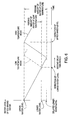
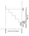
- the first delay time period is not always set to be a constant time period (for example, three seconds) as in Embodiment 1, but the first delay time period is designed to be modified in accordance with the deicing completion time period T 1. That is, the control means 46 has a delay time calculation unit 50, and the delay time calculation unit 50 is designed to calculate the first delay time period based on the deicing completion time period T 1 of deicing operation (refer to Fig. 12 ). Specifically, as shown in Fig.
- the first delay time period is set to be five seconds when the deicing completion time period T 1 is 40 seconds or less, and the first delay time period is reduced stepwise by one second per 52 seconds of the deicing completion time period T 1 between 40 seconds and 5 minutes (300 seconds).
- the first delay time period becomes four seconds when the deicing completion time period T 1 is 92 seconds, and the first delay time period becomes three seconds when the deicing completion time period T 1 is 144 seconds.
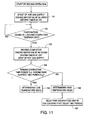
- the control means 46 allows a hot gas to be supplied to the evaporation tube 14 and also opens the deicing water valve 36 to supply deicing water to the ice making unit 16 from the external water supply source via the deicing water spray 34 (Step S1).
- the control means 46 activates the deicing timer 42 concurrently with starting deicing operation to keep time of the deicing completion time period T 1 .
- Step S3 when the temperature measured by the temperature gauge 20 reaches the deicing completion temperature (Yes in Step S2), the control means 46 finishes the deicing operation and also stops the deicing timer 42 to measure the deicing completion time period T 1 (Step S3).
- the control means 46 determines whether or not the deicing completion time period T 1 is equal to or greater than the deicing base elapsed time period U 3 (Step S4), and when the deicing completion time period T 1 is equal to or greater than the deicing base elapsed time period U 3 (Yes in Step S4), the control means 46 determines the water feeding mode to be in the low temperature mode (Step S5). In contrast, in a case where the deicing completion time period T 1 is shorter than the deicing base elapsed time period U 3 (No in Step S4), the control means 46 determines the water feeding mode to be in the high temperature mode (Step S6).
- the delay time calculation unit 50 determines the first delay time period from the deicing completion time period T 1 (Step S7). For example, in a case where the deicing completion time period T 1 is 92 seconds, the delay time calculation unit 50 determines the first delay time period to be four seconds.
- the water feeding mode and the first delay time period are determined. Then, when shifted to ice making operation, in a case of the high temperature mode, the timing of stopping water feeding is delayed by the first delay time period. That is, in the high temperature mode, water feeding is started when the water level of ice making water in the ice making water tank 18 reaches the lower water level, and at the point in time where the water level of the ice making water reaches the upper water level, the delay timer 44 keeps time of the first delay time period. Then, at the point in time where the delay timer 44 keeps time of the first delay time period (in the previous example, four seconds) calculated in the delay time calculation unit 50, the control means 46 stops water feeding.
- the automatic ice making machine 48 of Embodiment 3 by modifying the first delay time period in accordance with the deicing completion time period T 1 , as shown in Fig. 12 , it is possible to feed water in an appropriate feeding amount of water at high temperature corresponding to the temperature of makeup water (deicing water). Accordingly, more flexible water feeding can be carried out compared to a case of water feeding always in a constant feeding amount of water at high temperature, and thus a decrease in ice making capacity due to lack in water feeding can be prevented more securely.
- the first delay time period is modified stepwise by one second in accordance with the deicing completion time period T 1 , while the first delay time period may also be modified proportionally (linearly) in accordance with the deicing completion time period T 1 .
- the first delay time period is modified in accordance with the deicing completion time period T 1, while the second delay time period may also be modified in accordance with the deicing completion time period T 1 .
- Embodiment 4 a description is given below to an automatic ice making machine according to Embodiment 4. Also in Embodiment 4, descriptions are given only to configurations different from Embodiment 1 and descriptions for configurations same as Embodiment 1 are omitted by assigning same reference numerals.
- Fig. 13 is a schematic diagram illustrating an automatic ice making machine 52 according to Embodiment 4.
- a control means 56 according to Embodiment 4 is designed to determine the water feeding mode during ice making operation. That is, the control means 56 has, instead of the deicing timer 42 to keep time of the deicing completion time period T 1 , a built-in ice making timer 54 to keep time of a reference temperature reaching time period T 2 .
- an ice making base elapsed time period U 4 is preset, and the control means 56 is designed to compare the reference temperature reaching time period T 2 and the ice making base elapsed time period U 4 upon determining the water feeding mode.
- the reference temperature reaching time period T 2 refers to time required for the temperature on the exit side of the ice making unit 16 in the evaporation tube 14 (temperature measured by the temperature gauge 20) to reach a preset reference temperature from the start of ice making operation.
- This reference temperature refers to a temperature on the exit side of the ice making unit 16 at the time when ice making operation progresses to some extent to cool ice making water and the ice making unit 16 and thus ice blocks are started to be produced in the ice making unit 16.
- ice making water in the ice making water tank 18 at the time when ice making operation is started is water supplied as deicing water from the external water supply source during deicing operation, so that when the ice making water is high in temperature, it takes time to cool the ice making water. Accordingly, when ice making water is high in temperature, it takes time to decrease the temperature of a refrigerant on the exit side of the ice making unit 16, and the reference temperature reaching time period T 2 becomes longer in which the temperature measured by the temperature gauge 20 reaches the reference temperature.
- the ice making base elapsed time period U 4 refers to a time period required for the temperature gauge 20 to reach the reference temperature in a case of starting ice making operation in a state where ice making water at a predetermined base temperature is stored in the ice making water tank 18. For example, when the base temperature of ice making water is set at 10°C and the reference temperature is set at 2°C, the ice making base elapsed time period U 4 is three minutes.
- the control means 56 determines that the temperature of makeup water from the external water supply source identical to that of the ice making water (deicing water) is also high in temperature, and thus it determines the water feeding mode to be in the high temperature mode.
- the control means 56 determines that the temperature of makeup water from the external water supply source identical to that of ice making water (deicing water) is also low in temperature, and thus it determines the water feeding mode to be in the low temperature mode.
- the base temperature and the reference temperature of ice making water are set for each model of the automatic ice making machine 52, and the ice making base elapsed time period U4 is determined based on the base temperature and the reference temperature.
- the method of water feeding in the high temperature mode is designed to start water feeding after the second delay time period has passed since the water level of ice making water in the ice making water tank 18 reaches the lower water level.
- the second delay time period is always a constant time period (for example, three seconds)
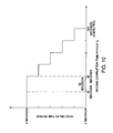
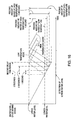
- the second delay time period is designed to be modified in accordance with the reference temperature reaching time period T 2 . That is, the control means 56 has a delay time calculation unit 58 and the delay time calculation unit 58 calculates the second delay time period based on the reference temperature reaching time period T 2 . For example, as shown in Fig.
- the second delay time period becomes 0 seconds when the reference temperature reaching time period T 2 is equal to or less than three minutes, and the second delay time period is designed to be increased stepwise by one second per 84 seconds of the reference temperature reaching time period T 2 between three and ten minutes and to be five seconds for ten minutes or more. Accordingly, the second delay time period becomes one second when the reference temperature reaching time period T 2 is four minutes and 24 seconds, and the second delay time period becomes two seconds when the reference temperature reaching time period T 2 is five minutes and 48 seconds. As thus described, by modifying the second delay time period in accordance with the reference temperature reaching time period T 2 , it becomes possible to feed water in an optimum feeding amount of water at high temperature depending on the temperature of ice making water (makeup water).
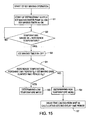
- the control means 56 allows a refrigerant to be supplied to the evaporation tube 14, and also activates the ice making water pump 30 to circulatively supply ice making water to the ice making unit 16 (Step S1).
- the ice making timer 54 activates the ice making timer 54 to keep time of the reference temperature reaching time period T 2 .
- ice making water supplied to the ice making water tank 18 in deicing operation is high in temperature in an initial stage of ice making operation, and thus is cooled while being circulatively supplied to the ice making unit 16. Accordingly, the temperature on the exit side of the ice making unit 16 in the evaporation tube 14 (temperature measured by the temperature gauge 20) becomes high depending on the temperature of ice making water at the time when ice making operation is started.
- Step S5 When the temperature of ice making water is gradually decreased as ice making operation progresses, the temperature measured by the temperature gauge 20 is also decreased. Then, when the temperature measured by the temperature gauge 20 reaches the reference temperature (2°C) (Yes in Step S2), the control means 56 stops the ice making timer 54 to measure the reference temperature reaching time period T 2 (Step S3). Then, it compares the reference temperature reaching time period T 2 and the ice making base elapsed time period U 4 (Step S4), and when the reference temperature reaching time period T 2 is equal to or less than the ice making base elapsed time period U 4 (Yes in Step S4), the control means 56 determines the water feeding mode to be in the low temperature mode (Step S5).
- the control means 56 determines the water feeding mode to be in the high temperature mode (Step S6). Further, in a case where the water feeding mode is determined to be in the high temperature mode, the control means 56 allows the delay time calculation unit 58 to calculate the second delay time period (Step S7). Then, the delay time calculation unit 58 calculates the second delay time period in accordance with the reference temperature reaching time period T 2 . For example, in a case where the reference temperature reaching time period T 2 is five minutes and 24 seconds, the delay time calculation unit 58 sets the second delay time period to be two seconds.
- the water feeding mode is determined during ice making operation, and the ice making operation is continued without change. Then, in a case of the high temperature mode, when the water level of ice making water in the ice making water tank 18 reaches the lower water level, the float switch 22 detects that and the control means 56 activates the delay timer 44. Then, when the time measured by the delay timer 44 becomes the second delay time period (for example, two seconds) calculated in the delay time calculation unit 58, the control means 56 opens the water feeding valve 40 to start water feeding. At this time, the water level of ice making water becomes the delayed lower water level.
- the control means 56 closes the water feeding valve 40 to stop water feeding. That is, in the high temperature mode, the timing of starting water feeding is delayed by the second delay time period calculated in the delay time calculation unit 58, so that it is possible to feed water in the feeding amount of water at high temperature of from the delayed lower water level to the upper water level. Moreover, an appropriate value is set for the second delay time period in accordance with the reference temperature reaching time period T 2 (temperature of ice making water), so that it is possible to carry out more flexible water feeding compared to a case of water feeding always in a constant feeding amount of water at high temperature (refer to Fig. 16 ). Accordingly, it is possible to eliminate waste of water feeding in the high temperature mode and thus the running cost becomes inexpensive, and also a decrease in ice making capacity due to lack in water feeding does not occur.
- water feeding is designed to be started after the water level of ice making water in the ice making water tank 18 reaches the lower water level and to stop water feeding when the water level of ice making water reaches the upper water level. Accordingly, in a case of ice making water (makeup water) at low temperature, less makeup water compared to the feeding amount of water at high temperature is fed, so that it is possible to prevent occurrence of deicing fault, and a failure or the like in the ice making unit 16 by production of huge ice blocks in the ice making unit 16.
- the second delay time period is modified stepwise by one second in accordance with the reference temperature reaching time period T 2 , while the second delay time period may also be modified proportionally (linearly) in accordance with the reference temperature reaching time period T 2 .
- the second delay time period is modified, while it is also possible to modify the first delay time period, as in Embodiment 3, in accordance with the reference temperature reaching time period T 2 .
- a description is given to a so-called flow-down type automatic ice making machine, while in the present invention to determine the water feeding mode during ice making operation, it is possible to employ a sealing type automatic ice making machine or the like of a closed cell system or an open cell system.
- the automatic ice making machine is not limited to Embodiments and the modification mentioned above but the following modifications are possible.
Landscapes
- Engineering & Computer Science (AREA)
- Physics & Mathematics (AREA)
- Mechanical Engineering (AREA)
- Thermal Sciences (AREA)
- General Engineering & Computer Science (AREA)
- Production, Working, Storing, Or Distribution Of Ice (AREA)
Applications Claiming Priority (2)
| Application Number | Priority Date | Filing Date | Title |
|---|---|---|---|
| JP2009074850A JP5198337B2 (ja) | 2009-03-25 | 2009-03-25 | 自動製氷機 |
| PCT/JP2009/069575 WO2010109724A1 (ja) | 2009-03-25 | 2009-11-18 | 自動製氷機 |
Publications (3)
| Publication Number | Publication Date |
|---|---|
| EP2413070A1 EP2413070A1 (en) | 2012-02-01 |
| EP2413070A4 EP2413070A4 (en) | 2013-01-09 |
| EP2413070B1 true EP2413070B1 (en) | 2014-04-16 |
Family
ID=42780426
Family Applications (1)
| Application Number | Title | Priority Date | Filing Date |
|---|---|---|---|
| EP09842334.6A Active EP2413070B1 (en) | 2009-03-25 | 2009-11-18 | Automatic ice maker |
Country Status (5)
| Country | Link |
|---|---|
| US (1) | US9146049B2 (enExample) |
| EP (1) | EP2413070B1 (enExample) |
| JP (1) | JP5198337B2 (enExample) |
| CN (1) | CN102348946B (enExample) |
| WO (1) | WO2010109724A1 (enExample) |
Families Citing this family (25)
| Publication number | Priority date | Publication date | Assignee | Title |
|---|---|---|---|---|
| CN102346448B (zh) * | 2010-08-03 | 2014-11-12 | 曼尼托沃食品服务有限公司 | 用于通知制冰周期启动时延的低压控制 |
| JP5755465B2 (ja) * | 2011-02-28 | 2015-07-29 | ホシザキ電機株式会社 | 自動製氷機 |
| US9625199B2 (en) * | 2012-07-11 | 2017-04-18 | Mainitowoc Foodservice Companies, Llc | Methods and apparatus for adjusting ice slab bridge thickness and initiate ice harvest following the freeze cycle |
| WO2014189476A1 (en) * | 2013-05-20 | 2014-11-27 | Enzi̇lhan Hakan Isik | Apparatus for recirculating cold water in ice machines |
| DE102014221318A1 (de) * | 2014-10-21 | 2016-04-21 | BSH Hausgeräte GmbH | Haushaltskältegerät mit Eisbereiter |
| US9385475B1 (en) | 2015-02-06 | 2016-07-05 | Cooper Technologies Company | Indicating handles for electrical connectors |
| KR101707636B1 (ko) * | 2016-04-25 | 2017-02-17 | 주식회사 카이저제빙기 | 신속제빙용 수직형 제빙기 |
| KR101867094B1 (ko) * | 2017-03-06 | 2018-06-14 | 주식회사 아이스트로 | 제빙기 |
| JP2019219095A (ja) * | 2018-06-19 | 2019-12-26 | ホシザキ株式会社 | 製氷機 |
| CN110794881B (zh) * | 2018-08-03 | 2023-12-19 | 星崎美国公司 | 制冰机中的超声波储箱控制 |
| US11506438B2 (en) | 2018-08-03 | 2022-11-22 | Hoshizaki America, Inc. | Ice machine |
| US11243017B2 (en) * | 2019-09-09 | 2022-02-08 | Haier Us Appliance Solutions, Inc. | Drained plumbing system for an ice maker |
| US11656017B2 (en) | 2020-01-18 | 2023-05-23 | True Manufacturing Co., Inc. | Ice maker |
| US11602059B2 (en) | 2020-01-18 | 2023-03-07 | True Manufacturing Co., Inc. | Refrigeration appliance with detachable electronics module |
| US11255589B2 (en) | 2020-01-18 | 2022-02-22 | True Manufacturing Co., Inc. | Ice maker |
| US11913699B2 (en) | 2020-01-18 | 2024-02-27 | True Manufacturing Co., Inc. | Ice maker |
| US11802727B2 (en) | 2020-01-18 | 2023-10-31 | True Manufacturing Co., Inc. | Ice maker |
| US11578905B2 (en) | 2020-01-18 | 2023-02-14 | True Manufacturing Co., Inc. | Ice maker, ice dispensing assembly, and method of deploying ice maker |
| US11391500B2 (en) | 2020-01-18 | 2022-07-19 | True Manufacturing Co., Inc. | Ice maker |
| US11620624B2 (en) | 2020-02-05 | 2023-04-04 | Walmart Apollo, Llc | Energy-efficient systems and methods for producing and vending ice |
| US11519652B2 (en) | 2020-03-18 | 2022-12-06 | True Manufacturing Co., Inc. | Ice maker |
| US11674731B2 (en) | 2021-01-13 | 2023-06-13 | True Manufacturing Co., Inc. | Ice maker |
| US11686519B2 (en) | 2021-07-19 | 2023-06-27 | True Manufacturing Co., Inc. | Ice maker with pulsed fill routine |
| CN114018310B (zh) * | 2021-09-17 | 2023-11-03 | 合肥美的洗衣机有限公司 | 下水通道结冰检测方法、装置、电子设备及存储介质 |
| CN113970219B (zh) * | 2021-10-27 | 2023-04-11 | 海信冰箱有限公司 | 冰箱及冰箱的控制方法 |
Family Cites Families (24)
| Publication number | Priority date | Publication date | Assignee | Title |
|---|---|---|---|---|
| JPS5749107Y2 (enExample) * | 1978-05-31 | 1982-10-27 | ||
| AU636726B2 (en) * | 1990-03-19 | 1993-05-06 | Mitsubishi Denki Kabushiki Kaisha | Air conditioning system |
| US5291747A (en) * | 1991-08-13 | 1994-03-08 | Hoshizaki Denki Kabushiki Kaisha | Electric control apparatus for ice making machine |
| JP3220248B2 (ja) | 1992-08-26 | 2001-10-22 | ホシザキ電機株式会社 | 流下式製氷機 |
| US5440895A (en) * | 1994-01-24 | 1995-08-15 | Copeland Corporation | Heat pump motor optimization and sensor fault detection |
| JP3292669B2 (ja) * | 1997-01-20 | 2002-06-17 | 株式会社東芝 | 冷蔵庫の自動製氷装置 |
| JP3890713B2 (ja) * | 1997-11-27 | 2007-03-07 | 株式会社デンソー | 冷凍サイクル装置 |
| JP2000258009A (ja) * | 1999-03-08 | 2000-09-22 | Hoshizaki Electric Co Ltd | 自動製氷機 |
| US7000422B2 (en) * | 2000-03-14 | 2006-02-21 | Hussmann Corporation | Refrigeration system and method of configuring the same |
| US6321548B1 (en) * | 2000-03-31 | 2001-11-27 | Heatcraft Inc. | Apparatus for automatically closing a cooling system expansion valve in response to power loss |
| AU2410601A (en) * | 2000-06-07 | 2001-12-17 | Samsung Electronics Co., Ltd. | System for controlling starting of air conditioner and control method thereof |
| WO2004083971A2 (en) * | 2003-03-13 | 2004-09-30 | Imi Cornelius Inc. | Icemaker control system |
| JP4255807B2 (ja) * | 2003-11-06 | 2009-04-15 | 株式会社不二工機 | 電磁リリーフ弁付膨張弁 |
| JP4693403B2 (ja) * | 2003-12-16 | 2011-06-01 | オットー・エゲルホフ・ゲーエムベーハー・ウント・コンパニ・カーゲー | 遮断弁、遮断弁を有するキット、及び膨張弁 |
| US7212887B2 (en) * | 2004-01-20 | 2007-05-01 | Carrier Corporation | Service and diagnostic tool for HVAC systems |
| KR100631539B1 (ko) * | 2004-10-26 | 2006-10-09 | 엘지전자 주식회사 | 멀티형 공기조화기의 통신선 오결선 검출시스템 및 방법 |
| ES2510665T3 (es) * | 2005-02-24 | 2014-10-21 | Mitsubishi Electric Corporation | Sistema de aire acondicionado |
| EP2021705B1 (en) * | 2006-06-01 | 2013-03-20 | Carrier Corporation | System and method for controlled expansion valve adjustment |
| WO2008016348A1 (en) * | 2006-08-01 | 2008-02-07 | Carrier Corporation | Operation and control of tandem compressors and reheat function |
| JP2008064322A (ja) * | 2006-09-04 | 2008-03-21 | Hoshizaki Electric Co Ltd | 自動製氷機 |
| US20080216490A1 (en) * | 2007-03-08 | 2008-09-11 | Hoshizaki Denki Kabushiki Kaisha | Operation method for automatic ice maker |
| JP5052173B2 (ja) * | 2007-03-23 | 2012-10-17 | ホシザキ電機株式会社 | 自動製氷機の運転方法 |
| WO2009098751A1 (ja) * | 2008-02-04 | 2009-08-13 | Mitsubishi Electric Corporation | 空調給湯複合システム |
| EP2309213B1 (en) * | 2009-10-12 | 2013-05-01 | LG Electronics Inc. | Air conditioning system and method for controlling operation thereof |
-
2009
- 2009-03-25 JP JP2009074850A patent/JP5198337B2/ja not_active Expired - Fee Related
- 2009-11-18 US US13/201,207 patent/US9146049B2/en active Active
- 2009-11-18 EP EP09842334.6A patent/EP2413070B1/en active Active
- 2009-11-18 CN CN2009801579663A patent/CN102348946B/zh not_active Expired - Fee Related
- 2009-11-18 WO PCT/JP2009/069575 patent/WO2010109724A1/ja not_active Ceased
Also Published As
| Publication number | Publication date |
|---|---|
| EP2413070A4 (en) | 2013-01-09 |
| JP2010230177A (ja) | 2010-10-14 |
| US9146049B2 (en) | 2015-09-29 |
| US20120000226A1 (en) | 2012-01-05 |
| CN102348946A (zh) | 2012-02-08 |
| EP2413070A1 (en) | 2012-02-01 |
| WO2010109724A1 (ja) | 2010-09-30 |
| JP5198337B2 (ja) | 2013-05-15 |
| CN102348946B (zh) | 2013-08-28 |
Similar Documents
| Publication | Publication Date | Title |
|---|---|---|
| EP2413070B1 (en) | Automatic ice maker | |
| KR101688133B1 (ko) | 제빙장치 및 이를 구비한 냉장고 및 이 냉장고의 제빙방법 | |
| US8042344B2 (en) | Automatic ice making machine and operation method therefor | |
| KR101455392B1 (ko) | 냉장고용 제빙 어셈블리 및 제빙 어셈블리의 수위 감지방법 | |
| EP2414750B1 (en) | Ice making technology | |
| KR101668251B1 (ko) | 냉장고 및 그 동작방법 | |
| US20080092567A1 (en) | Ice maker with ice bin level control | |
| EP1589305A1 (en) | Ice-Making Apparatus | |
| KR101659021B1 (ko) | 제빙장치 및 이를 구비한 냉장고 | |
| US20180017313A1 (en) | Refrigerator and method of operating the same | |
| KR102036897B1 (ko) | 제빙장치 제어시스템 및 그 제어방법 | |
| KR101707636B1 (ko) | 신속제빙용 수직형 제빙기 | |
| KR101867094B1 (ko) | 제빙기 | |
| JP5294781B2 (ja) | 自動製氷機の異常検知方法 | |
| KR101718019B1 (ko) | 제빙기용 절전 장치 및 제빙기의 절전 방법 | |
| KR20190068107A (ko) | 제빙장치 제어시스템 및 그 제어방법 | |
| KR20190068108A (ko) | 제빙장치 제어시스템 및 그 제어방법 | |
| KR100636553B1 (ko) | 자동 제빙기의 급수 제어 장치 및 급수 제어 방법 | |
| KR100755866B1 (ko) | 냉각 장치 및 이의 제어 방법 | |
| KR101442838B1 (ko) | 냉장고용 제빙 어셈블리 및 제빙 어셈블리의 물넘침 방지방법 | |
| KR101672054B1 (ko) | 냉장고용 제빙기의 제어방법 | |
| JPH09145210A (ja) | 自動製氷機付き冷凍冷蔵庫 | |
| JP2020118321A (ja) | 流下式製氷機 | |
| JP4749886B2 (ja) | 製氷機 | |
| KR100557764B1 (ko) | 제빙장치 및 그 제어방법 |
Legal Events
| Date | Code | Title | Description |
|---|---|---|---|
| PUAI | Public reference made under article 153(3) epc to a published international application that has entered the european phase |
Free format text: ORIGINAL CODE: 0009012 |
|
| 17P | Request for examination filed |
Effective date: 20110818 |
|
| AK | Designated contracting states |
Kind code of ref document: A1 Designated state(s): AT BE BG CH CY CZ DE DK EE ES FI FR GB GR HR HU IE IS IT LI LT LU LV MC MK MT NL NO PL PT RO SE SI SK SM TR |
|
| DAX | Request for extension of the european patent (deleted) | ||
| A4 | Supplementary search report drawn up and despatched |
Effective date: 20121206 |
|
| RIC1 | Information provided on ipc code assigned before grant |
Ipc: F25C 1/22 20060101AFI20121130BHEP |
|
| GRAP | Despatch of communication of intention to grant a patent |
Free format text: ORIGINAL CODE: EPIDOSNIGR1 |
|
| INTG | Intention to grant announced |
Effective date: 20131129 |
|
| GRAS | Grant fee paid |
Free format text: ORIGINAL CODE: EPIDOSNIGR3 |
|
| GRAA | (expected) grant |
Free format text: ORIGINAL CODE: 0009210 |
|
| AK | Designated contracting states |
Kind code of ref document: B1 Designated state(s): AT BE BG CH CY CZ DE DK EE ES FI FR GB GR HR HU IE IS IT LI LT LU LV MC MK MT NL NO PL PT RO SE SI SK SM TR |
|
| REG | Reference to a national code |
Ref country code: GB Ref legal event code: FG4D |
|
| REG | Reference to a national code |
Ref country code: CH Ref legal event code: EP |
|
| REG | Reference to a national code |
Ref country code: AT Ref legal event code: REF Ref document number: 662816 Country of ref document: AT Kind code of ref document: T Effective date: 20140515 |
|
| REG | Reference to a national code |
Ref country code: IE Ref legal event code: FG4D |
|
| REG | Reference to a national code |
Ref country code: DE Ref legal event code: R096 Ref document number: 602009023373 Country of ref document: DE Effective date: 20140528 |
|
| REG | Reference to a national code |
Ref country code: AT Ref legal event code: MK05 Ref document number: 662816 Country of ref document: AT Kind code of ref document: T Effective date: 20140416 |
|
| REG | Reference to a national code |
Ref country code: NL Ref legal event code: VDEP Effective date: 20140416 |
|
| REG | Reference to a national code |
Ref country code: LT Ref legal event code: MG4D |
|
| PG25 | Lapsed in a contracting state [announced via postgrant information from national office to epo] |
Ref country code: IS Free format text: LAPSE BECAUSE OF FAILURE TO SUBMIT A TRANSLATION OF THE DESCRIPTION OR TO PAY THE FEE WITHIN THE PRESCRIBED TIME-LIMIT Effective date: 20140816 Ref country code: CY Free format text: LAPSE BECAUSE OF FAILURE TO SUBMIT A TRANSLATION OF THE DESCRIPTION OR TO PAY THE FEE WITHIN THE PRESCRIBED TIME-LIMIT Effective date: 20140416 Ref country code: NL Free format text: LAPSE BECAUSE OF FAILURE TO SUBMIT A TRANSLATION OF THE DESCRIPTION OR TO PAY THE FEE WITHIN THE PRESCRIBED TIME-LIMIT Effective date: 20140416 Ref country code: BG Free format text: LAPSE BECAUSE OF FAILURE TO SUBMIT A TRANSLATION OF THE DESCRIPTION OR TO PAY THE FEE WITHIN THE PRESCRIBED TIME-LIMIT Effective date: 20140716 Ref country code: GR Free format text: LAPSE BECAUSE OF FAILURE TO SUBMIT A TRANSLATION OF THE DESCRIPTION OR TO PAY THE FEE WITHIN THE PRESCRIBED TIME-LIMIT Effective date: 20140717 Ref country code: NO Free format text: LAPSE BECAUSE OF FAILURE TO SUBMIT A TRANSLATION OF THE DESCRIPTION OR TO PAY THE FEE WITHIN THE PRESCRIBED TIME-LIMIT Effective date: 20140716 Ref country code: LT Free format text: LAPSE BECAUSE OF FAILURE TO SUBMIT A TRANSLATION OF THE DESCRIPTION OR TO PAY THE FEE WITHIN THE PRESCRIBED TIME-LIMIT Effective date: 20140416 Ref country code: FI Free format text: LAPSE BECAUSE OF FAILURE TO SUBMIT A TRANSLATION OF THE DESCRIPTION OR TO PAY THE FEE WITHIN THE PRESCRIBED TIME-LIMIT Effective date: 20140416 |
|
| PG25 | Lapsed in a contracting state [announced via postgrant information from national office to epo] |
Ref country code: LV Free format text: LAPSE BECAUSE OF FAILURE TO SUBMIT A TRANSLATION OF THE DESCRIPTION OR TO PAY THE FEE WITHIN THE PRESCRIBED TIME-LIMIT Effective date: 20140416 Ref country code: AT Free format text: LAPSE BECAUSE OF FAILURE TO SUBMIT A TRANSLATION OF THE DESCRIPTION OR TO PAY THE FEE WITHIN THE PRESCRIBED TIME-LIMIT Effective date: 20140416 Ref country code: ES Free format text: LAPSE BECAUSE OF FAILURE TO SUBMIT A TRANSLATION OF THE DESCRIPTION OR TO PAY THE FEE WITHIN THE PRESCRIBED TIME-LIMIT Effective date: 20140416 Ref country code: HR Free format text: LAPSE BECAUSE OF FAILURE TO SUBMIT A TRANSLATION OF THE DESCRIPTION OR TO PAY THE FEE WITHIN THE PRESCRIBED TIME-LIMIT Effective date: 20140416 Ref country code: SE Free format text: LAPSE BECAUSE OF FAILURE TO SUBMIT A TRANSLATION OF THE DESCRIPTION OR TO PAY THE FEE WITHIN THE PRESCRIBED TIME-LIMIT Effective date: 20140416 Ref country code: PL Free format text: LAPSE BECAUSE OF FAILURE TO SUBMIT A TRANSLATION OF THE DESCRIPTION OR TO PAY THE FEE WITHIN THE PRESCRIBED TIME-LIMIT Effective date: 20140416 |
|
| PG25 | Lapsed in a contracting state [announced via postgrant information from national office to epo] |
Ref country code: PT Free format text: LAPSE BECAUSE OF FAILURE TO SUBMIT A TRANSLATION OF THE DESCRIPTION OR TO PAY THE FEE WITHIN THE PRESCRIBED TIME-LIMIT Effective date: 20140818 |
|
| REG | Reference to a national code |
Ref country code: DE Ref legal event code: R097 Ref document number: 602009023373 Country of ref document: DE |
|
| PG25 | Lapsed in a contracting state [announced via postgrant information from national office to epo] |
Ref country code: SK Free format text: LAPSE BECAUSE OF FAILURE TO SUBMIT A TRANSLATION OF THE DESCRIPTION OR TO PAY THE FEE WITHIN THE PRESCRIBED TIME-LIMIT Effective date: 20140416 Ref country code: RO Free format text: LAPSE BECAUSE OF FAILURE TO SUBMIT A TRANSLATION OF THE DESCRIPTION OR TO PAY THE FEE WITHIN THE PRESCRIBED TIME-LIMIT Effective date: 20140416 Ref country code: EE Free format text: LAPSE BECAUSE OF FAILURE TO SUBMIT A TRANSLATION OF THE DESCRIPTION OR TO PAY THE FEE WITHIN THE PRESCRIBED TIME-LIMIT Effective date: 20140416 Ref country code: BE Free format text: LAPSE BECAUSE OF FAILURE TO SUBMIT A TRANSLATION OF THE DESCRIPTION OR TO PAY THE FEE WITHIN THE PRESCRIBED TIME-LIMIT Effective date: 20140416 Ref country code: DK Free format text: LAPSE BECAUSE OF FAILURE TO SUBMIT A TRANSLATION OF THE DESCRIPTION OR TO PAY THE FEE WITHIN THE PRESCRIBED TIME-LIMIT Effective date: 20140416 Ref country code: CZ Free format text: LAPSE BECAUSE OF FAILURE TO SUBMIT A TRANSLATION OF THE DESCRIPTION OR TO PAY THE FEE WITHIN THE PRESCRIBED TIME-LIMIT Effective date: 20140416 |
|
| PLBE | No opposition filed within time limit |
Free format text: ORIGINAL CODE: 0009261 |
|
| STAA | Information on the status of an ep patent application or granted ep patent |
Free format text: STATUS: NO OPPOSITION FILED WITHIN TIME LIMIT |
|
| 26N | No opposition filed |
Effective date: 20150119 |
|
| PG25 | Lapsed in a contracting state [announced via postgrant information from national office to epo] |
Ref country code: IT Free format text: LAPSE BECAUSE OF FAILURE TO SUBMIT A TRANSLATION OF THE DESCRIPTION OR TO PAY THE FEE WITHIN THE PRESCRIBED TIME-LIMIT Effective date: 20140416 |
|
| REG | Reference to a national code |
Ref country code: DE Ref legal event code: R097 Ref document number: 602009023373 Country of ref document: DE Effective date: 20150119 |
|
| PG25 | Lapsed in a contracting state [announced via postgrant information from national office to epo] |
Ref country code: MC Free format text: LAPSE BECAUSE OF FAILURE TO SUBMIT A TRANSLATION OF THE DESCRIPTION OR TO PAY THE FEE WITHIN THE PRESCRIBED TIME-LIMIT Effective date: 20140416 Ref country code: LU Free format text: LAPSE BECAUSE OF FAILURE TO SUBMIT A TRANSLATION OF THE DESCRIPTION OR TO PAY THE FEE WITHIN THE PRESCRIBED TIME-LIMIT Effective date: 20141118 |
|
| REG | Reference to a national code |
Ref country code: CH Ref legal event code: PL |
|
| PG25 | Lapsed in a contracting state [announced via postgrant information from national office to epo] |
Ref country code: LI Free format text: LAPSE BECAUSE OF NON-PAYMENT OF DUE FEES Effective date: 20141130 Ref country code: SI Free format text: LAPSE BECAUSE OF FAILURE TO SUBMIT A TRANSLATION OF THE DESCRIPTION OR TO PAY THE FEE WITHIN THE PRESCRIBED TIME-LIMIT Effective date: 20140416 Ref country code: CH Free format text: LAPSE BECAUSE OF NON-PAYMENT OF DUE FEES Effective date: 20141130 |
|
| REG | Reference to a national code |
Ref country code: IE Ref legal event code: MM4A |
|
| REG | Reference to a national code |
Ref country code: FR Ref legal event code: PLFP Year of fee payment: 7 |
|
| PG25 | Lapsed in a contracting state [announced via postgrant information from national office to epo] |
Ref country code: IE Free format text: LAPSE BECAUSE OF NON-PAYMENT OF DUE FEES Effective date: 20141118 |
|
| PG25 | Lapsed in a contracting state [announced via postgrant information from national office to epo] |
Ref country code: SM Free format text: LAPSE BECAUSE OF FAILURE TO SUBMIT A TRANSLATION OF THE DESCRIPTION OR TO PAY THE FEE WITHIN THE PRESCRIBED TIME-LIMIT Effective date: 20140416 |
|
| PG25 | Lapsed in a contracting state [announced via postgrant information from national office to epo] |
Ref country code: TR Free format text: LAPSE BECAUSE OF FAILURE TO SUBMIT A TRANSLATION OF THE DESCRIPTION OR TO PAY THE FEE WITHIN THE PRESCRIBED TIME-LIMIT Effective date: 20140416 Ref country code: HU Free format text: LAPSE BECAUSE OF FAILURE TO SUBMIT A TRANSLATION OF THE DESCRIPTION OR TO PAY THE FEE WITHIN THE PRESCRIBED TIME-LIMIT; INVALID AB INITIO Effective date: 20091118 Ref country code: MT Free format text: LAPSE BECAUSE OF FAILURE TO SUBMIT A TRANSLATION OF THE DESCRIPTION OR TO PAY THE FEE WITHIN THE PRESCRIBED TIME-LIMIT Effective date: 20140416 |
|
| REG | Reference to a national code |
Ref country code: DE Ref legal event code: R082 Ref document number: 602009023373 Country of ref document: DE Representative=s name: PRUEFER & PARTNER MBB PATENTANWAELTE RECHTSANW, DE Ref country code: DE Ref legal event code: R081 Ref document number: 602009023373 Country of ref document: DE Owner name: HOSHIZAKI CORPORATION, TOYOAKE-SHI, JP Free format text: FORMER OWNER: HOSHIZAKI DENKI K.K., TOYOAKE, AICHI, JP |
|
| REG | Reference to a national code |
Ref country code: FR Ref legal event code: PLFP Year of fee payment: 8 |
|
| REG | Reference to a national code |
Ref country code: FR Ref legal event code: CD Owner name: HOSHIZAKI CORPORATION, JP Effective date: 20161212 |
|
| REG | Reference to a national code |
Ref country code: FR Ref legal event code: PLFP Year of fee payment: 9 |
|
| PG25 | Lapsed in a contracting state [announced via postgrant information from national office to epo] |
Ref country code: MK Free format text: LAPSE BECAUSE OF FAILURE TO SUBMIT A TRANSLATION OF THE DESCRIPTION OR TO PAY THE FEE WITHIN THE PRESCRIBED TIME-LIMIT Effective date: 20140416 |
|
| REG | Reference to a national code |
Ref country code: FR Ref legal event code: PLFP Year of fee payment: 10 |
|
| P01 | Opt-out of the competence of the unified patent court (upc) registered |
Effective date: 20230428 |
|
| PGFP | Annual fee paid to national office [announced via postgrant information from national office to epo] |
Ref country code: DE Payment date: 20241001 Year of fee payment: 16 |
|
| PGFP | Annual fee paid to national office [announced via postgrant information from national office to epo] |
Ref country code: GB Payment date: 20241001 Year of fee payment: 16 |
|
| PGFP | Annual fee paid to national office [announced via postgrant information from national office to epo] |
Ref country code: FR Payment date: 20250930 Year of fee payment: 17 |