EP2409939B2 - Falt- und Stapel-Anlage für Wellpappebahnen - Google Patents
Falt- und Stapel-Anlage für Wellpappebahnen Download PDFInfo
- Publication number
- EP2409939B2 EP2409939B2 EP11174201.1A EP11174201A EP2409939B2 EP 2409939 B2 EP2409939 B2 EP 2409939B2 EP 11174201 A EP11174201 A EP 11174201A EP 2409939 B2 EP2409939 B2 EP 2409939B2
- Authority
- EP
- European Patent Office
- Prior art keywords
- corrugated cardboard
- web
- folding
- elements
- installation according
- Prior art date
- Legal status (The legal status is an assumption and is not a legal conclusion. Google has not performed a legal analysis and makes no representation as to the accuracy of the status listed.)
- Active
Links
Images


Classifications
-
- B—PERFORMING OPERATIONS; TRANSPORTING
- B65—CONVEYING; PACKING; STORING; HANDLING THIN OR FILAMENTARY MATERIAL
- B65H—HANDLING THIN OR FILAMENTARY MATERIAL, e.g. SHEETS, WEBS, CABLES
- B65H45/00—Folding thin material
- B65H45/02—Folding limp material without application of pressure to define or form crease lines
- B65H45/06—Folding webs
- B65H45/10—Folding webs transversely
- B65H45/101—Folding webs transversely in combination with laying, i.e. forming a zig-zag pile
- B65H45/1015—Folding webs provided with predefined fold lines; Refolding prefolded webs, e.g. fanfolded continuous forms
-
- B—PERFORMING OPERATIONS; TRANSPORTING
- B65—CONVEYING; PACKING; STORING; HANDLING THIN OR FILAMENTARY MATERIAL
- B65H—HANDLING THIN OR FILAMENTARY MATERIAL, e.g. SHEETS, WEBS, CABLES
- B65H31/00—Pile receivers
- B65H31/32—Auxiliary devices for receiving articles during removal of a completed pile
-
- B—PERFORMING OPERATIONS; TRANSPORTING
- B65—CONVEYING; PACKING; STORING; HANDLING THIN OR FILAMENTARY MATERIAL
- B65H—HANDLING THIN OR FILAMENTARY MATERIAL, e.g. SHEETS, WEBS, CABLES
- B65H45/00—Folding thin material
-
- B—PERFORMING OPERATIONS; TRANSPORTING
- B65—CONVEYING; PACKING; STORING; HANDLING THIN OR FILAMENTARY MATERIAL
- B65H—HANDLING THIN OR FILAMENTARY MATERIAL, e.g. SHEETS, WEBS, CABLES
- B65H45/00—Folding thin material
- B65H45/12—Folding articles or webs with application of pressure to define or form crease lines
- B65H45/20—Zig-zag folders
Definitions
- the invention relates to a system and a method for folding and stacking corrugated cardboard webs.
- the invention is not limited to the use of corrugated cardboard webs.
- An entrainment device which consists of two conveyor belts that are arranged on both sides of the web of corrugated cardboard and move synchronously with one another, between which several ropes are stretched. The ropes engage in folds in the corrugated cardboard web and place the corrugated cardboard web, which is folded in the form of a fan-fold, into a stack.
- the known device has the disadvantage that only a predetermined format can be folded.
- a chain driver with a large number of driver elements is known.
- the device is used to convey a zigzag-folded paper web along a predetermined circular path. With this device, it is not possible to convey a paper web along a linear conveying path. Furthermore, independent control of the individual drivers is also not possible.
- the invention is based on the object of creating a system and a method which simplify the folding and stacking of endless corrugated cardboard webs when changing formats. Furthermore, the system and the method should be adaptable to different formats as simply as possible. A stepless format setting should preferably be possible.
- the essence of the invention is that the engagement elements in the folding device are guided independently of one another.
- the engagement elements can preferably be driven individually or independently of one another. They can advantageously be accelerated and / or braked individually. Due to the independent guidance of the engagement elements, a format change can be carried out easily. With a format change, the distance between the engagement elements can easily be changed. The distance between the engagement elements can thus be easily adapted to a changed distance between the folds in the corrugated cardboard web.
- the engagement elements move relative to one another. At least two, preferably at least three, more preferably four and most preferably five engagement elements are provided. A maximum of seven engagement elements are advantageously present.
- the engagement elements can be designed as elongated elements. They are preferably chains, cords, ropes, rods, ribbons, wires or the like. The chains, cords, ropes, ribbons or wires are then taut.
- the guide device according to claim 2 ensures safe and precise guidance of the engagement elements. It specifies a movement path or trajectory for the engagement elements.
- the at least first circulating element according to claim 3 ensures a functionally reliable and targeted displacement of the first engagement element.
- Exactly one first circulating element can be provided. However, several, preferably two, first circulating elements can also be provided, which then form a circulating element unit or a circulating element pair.
- the first circulation elements preferably run synchronously.
- the at least second circulating element according to claim 4 ensures a functionally reliable and targeted displacement of the at least second
- Exactly one second circulating element can be provided. However, several, preferably two, second circulating elements can also be provided, which then form a circulating element unit or a circulating element pair. The second circulation elements preferably run synchronously.
- pairs of circulating elements are preferably provided.
- the circulating elements of a circulating element pair are preferably coupled to one another by the associated engagement element. They run synchronously.
- the circulating elements are preferably endless elements. In particular, they are flexible or pliable.
- the circulation elements can be bands, belts, ropes, cords, chains or toothed belts.
- the circulation elements assigned to the various engagement elements can be moved independently of one another.
- the embodiment according to claim 5 leads to a guide device which is extremely space-saving and therefore inexpensive to manufacture.
- the first circulating element and the at least second circulating element can be driven independently of one another.
- the circulation elements are assigned their own, independent drives.
- a mechanical, pairwise synchronization of the circulation elements is possible.
- the rising lifting section according to claim 7 causes a functionally reliable and targeted lifting of the corrugated cardboard web.
- the web of corrugated cardboard is raised by the rising course of the circulating elements in the lifting section in the conveying direction, which there is also a corresponding raising of the engaging elements causes.
- the engagement elements are in engagement with the web of corrugated cardboard and take the web of corrugated cardboard with them accordingly.
- the web of corrugated cardboard is thus preferably deflected upwards from its original web in the lifting section.
- the corrugated cardboard web is folded simply and functionally reliable.
- the web of corrugated cardboard is lowered in the conveying direction by the sloping course of the circulating elements in the depositing section, which also brings about a corresponding lowering of the engaging elements there.
- the engagement elements are in engagement with the corrugated cardboard web and take the corrugated cardboard web with them accordingly.
- the web of corrugated cardboard is thus preferably lowered again in the depositing section.
- the deposit section is preferably arcuate, more preferably arcuate. It preferably has essentially the shape of a quarter-circle arc.
- the circulating elements are guided along the lifting section, the laying section and the return section.
- the lifting section, the depositing section and the return section thus determine the movement path or trajectory of the circulating elements and thus also of the engagement elements.
- the path of movement is therefore preferably closed or endless all round.
- the depositing support element according to claim 10 results in particularly good guidance of the free folds on the one hand.
- the folding or laying down of the corrugated cardboard web is supported.
- the free folds are located opposite the folds that are carried along by the engagement elements. Operational disruptions in the system can thus be effectively prevented.
- the lifting table according to claim 11 enables the stacks to be picked up in a particularly simple and secure manner. It can be adjusted to the height of the respective stack.
- the embodiment according to claim 12 enables the folded corrugated cardboard web to be separated by machine.
- the separation preferably takes place in the area of a fold. It is advantageous if there is a separation in the event of a format change.
- the at least one cutting knife and the at least one counter-element according to claim 13 enable the corrugated cardboard web to be cut cleanly and quickly.
- the at least one counter-element quasi forms an abutment for the at least one separating knife.
- the at least one separating knife can penetrate into the counter-element.
- the counter-element preferably has a corresponding penetration recess. It is advantageous if the penetration recess is designed as a groove.
- the penetration recess is favorably open to the at least one cutting knife.
- the at least one separating knife can be guided along the fold at which the separation is to take place in order to separate the web of corrugated cardboard. It is preferably designed as a circular knife. Other knife shapes or designs are alternatively possible.
- the cutting knife and the counter-element are movable relative to one another. They can thus be moved between a closed disconnected position and an open non-disconnected position.
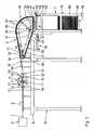
- a system for folding and stacking an endless web of corrugated cardboard 1 is in the Figs. 1 to 3 only indicated schematically.
- the web of corrugated cardboard 1 is conveyed in the system essentially in a conveying direction 2.
- the installation comprises a corrugated cardboard manufacturing device 3.
- Such a corrugated cardboard manufacturing device 3 is used to manufacture the corrugated cardboard web 1 and is, for example, made from FIG DE 103 12 600 A1 , to which reference is hereby made, is known.
- the corrugated cardboard web 1 which can be produced endlessly by means of the corrugated cardboard manufacturing device 3 can have a largely arbitrary number of layers.
- the corrugated cardboard web 1 has a total thickness D.
- the system also comprises a squeezing device 4, a folding device 5, a separating device 6 and a stacking device 7.
- the squeezing device 4 is located downstream of the corrugated cardboard manufacturing device.
- Device 3 arranged, while the folding device 5 is provided downstream of the squeezing device 4.
- the separating device 6 is in turn arranged downstream of the folding device 5.
- the stacking device 7 is located downstream of the separating device 6.
- the squeezing device 4 is arranged on a first platform 8 which is firmly connected to the floor via a first frame 9.
- the stacking device 7 is firmly connected to the floor via a second frame 10.
- the separating device is also on the second frame 10 6 attached.
- the folding device 5 is connected to the first frame 9 and / or the second frame 10 via a third frame 11.
- the frames 9, 10, 11 together form a holding frame for the system.
- the holding frame enables a flexible, modular structure of the system.
- the squeezing device 4 is described in more detail below.
- the squeezing device 4 has an insertion section 12 with a support surface 13. In the area of the insertion section 12, two insertion rollers 14 are arranged.
- the infeed rollers 14 are cylindrical and can each be rotated about an infeed roller axis which is perpendicular or essentially perpendicular to the conveying direction 2.
- the infeed rollers 14 can in particular be drivable in rotation.
- the squeezing device 4 comprises at least one pair of embossing rollers 15, which are each rotatable about an embossing roller axis.
- the embossing rollers 15 can preferably be driven in rotation by means of a drive device not shown in the figures.
- the drive is advantageously clocked intermittently.
- the embossing roller axes are aligned parallel to one another and perpendicular or essentially perpendicular to the conveying direction 2. Like the infeed roller axes, they are arranged vertically one above the other. The distance between the embossing roller axes is adjustable.
- a feed-through gap 16 with a free opening is formed between the surfaces of the embossing rollers 15.
- the free opening of the feed-through gap 16 is at least as large as the thickness D of the corrugated cardboard web 1. It is preferably adapted to the thickness D of the corrugated cardboard web 1 in such a way that the embossing rollers 15 rest against the corrugated cardboard web 1 with a friction fit, but the corrugated cardboard web 1 can pass between the embossing rollers 15 without deformation.
- the two embossing rollers 15 are at least largely identical. They have a circumference in the range from 80 cm to 140 cm.
- the embossing rollers 15 each have at least one embossing element 17 on their surface.
- the embossing element 17 is bar-shaped and blunt. It has an extension in the radial direction of the respective embossing roller 15, that is to say perpendicular to the surface of the corresponding embossing roller 15, which is less than half of the free opening.
- the embossing element 17 is formed continuously. However, it can also be designed in the form of a rake, that is to say interrupted.
- the embossing elements 17 are arranged on the circumference of the embossing rollers 15 in such a way that they meet each other with each revolution of the embossing rollers 15 about the embossing roller axes.
- the embossing elements 17 meet, the free opening of the feed-through gap 16 is reduced to a value which is smaller than the thickness D of the corrugated cardboard web 1.
- the corrugated cardboard web 1 can thus be squeezed by means of the embossing elements 17.
- the embossing elements 17 are currently in the feed-through gap 16. They are there opposite one another.
- the embossing elements 17 are preferably aligned parallel to the embossing roller axes in order to emboss folds 18 in the web of corrugated cardboard 1 which are perpendicular or substantially perpendicular to the conveying direction 2 and thus also perpendicular or substantially perpendicular to it the longitudinal direction of the corrugated cardboard web 1 are oriented.
- the distance between two successive folds 18 corresponds in one embodiment to the circumference of the embossing rollers 15.
- the folds 18 form intended kinks in the web of corrugated cardboard 1, along which it can be folded particularly easily.
- the corrugated cardboard web 1 has a smaller thickness in the region of the folds 18 and thus a lower flexural elasticity than in the region outside the folds 18. It can therefore buckle particularly easily in the region of the folds 18.
- embossing rollers 15 As an alternative to this, it is possible to see only one of the embossing rollers 15 with an embossing element 17.
- the circumference of the embossing roller 15 without the embossing element 17 is not subject to any special requirements. It is largely freely selectable and can, in particular, differ from the circumference of the embossing roller 15 with the embossing element 17.
- embossing rollers 15 are provided, the circumference of which corresponds precisely to an integral multiple of the desired distance between two successive folds 18 in the web of corrugated cardboard 1.
- the embossing rollers 15 of this type have a corresponding number of embossing elements 17 on their surface.
- the embossing elements 17 are evenly distributed over the circumference of the embossing rollers 15, that is to say the angular distance between two respectively adjacent embossing elements 17 is always the same.
- the embossing elements 17 are interchangeable. In this way, the distance between two successive folds 18 in the web of corrugated cardboard 1, which just corresponds to the circumference of the embossing rollers 15, can be set in a simple manner.
- the squeezing device 4 has an outlet section 19 which is provided downstream of the insertion section 12.
- outlet rollers 20 are arranged with outlet roller axes which run parallel to the infeed roller axes.
- the outlet rollers 20 arranged below the corrugated cardboard web 1 can be part of a transport unit 21 which can have supports 22 for storing the outlet rollers 20
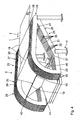
- the folding device 5 is arranged downstream of the squeezing device 4, that is to say downstream of it in the conveying direction 2.
- the folding device 5 comprises a guide device 23 which has an entrance area 24.
- the guide device 23 is in turn formed by two guide units 25, which are of essentially identical design and are arranged perpendicular to the conveying direction 2 next to one another and at a distance from one another.
- Each guide unit 25 is formed by a plurality of rigid frame parts 26 which are firmly connected to one another.
- the frame parts 26 are arranged perpendicular to the conveying direction 2 next to one another and at a distance from one another. They are of essentially identical design and are oriented vertically.
- the frame 11 is fastened to the outer frame parts 26.
- the guide device 23 has a lifting section 27 which adjoins the input area 24 in the conveying direction 2.
- the lifting section 27 is arranged obliquely to a horizontal and thus extends in an inclined plane. It is arranged at an angle ⁇ to the horizontal.
- the angle a is between 2 ° and 20 °, preferably between 5 ° and 15 °. Most preferably, the angle ⁇ is about 10 °.
- the guide device 23 also has a depositing section 28, which adjoins the lifting section 27 in the conveying direction 2.
- the deposit section 28 is arcuate. It is preferably designed as an arc of a circle which extends over an angular range from approximately 90 ° to 130 °, preferably from 100 ° to 120 °, and most preferably encloses an angle of 110 °.
- the deposit section 28 still rises over a small area on the upstream side. In the remaining area of the depositing section 28, the latter slopes down in the conveying direction 2.
- the guide device 23 also has a return section 29, which is connected to the deposit section 28 on the downstream side and to the lifting section 27 on the upstream side.
- the return section 29 extends essentially below the lift section 27 and the deposit section 28. It has a first return area 30 and a second inclined return area 31.
- the return area 30 closes downstream of the deposit -Section 28 and runs essentially horizontally, while the return area 31 extends from the return area 30 obliquely upwards to the horizontal.
- the frame parts 26 of the guide device 23 are designed in accordance with the sections 27, 28, 29. They are each closed on the circumference.
- the frame parts 26 of a guide unit 25 are firmly connected and combined by connecting pieces 32.
- the connecting pieces 32 also ensure that the individual frame parts 26 of a guide unit 25 are arranged at a distance from one another. There is a preferably constant, horizontal distance between these frame parts 26.
- a circulating element 33 which is designed to be closed on the circumference and is guided laterally by the corresponding frame parts 26.
- the circulation elements 33 are thus endless. They are pliable or flexible.
- n frame parts 26 per guide unit 25 n-1 circulating elements 33 are provided per guide unit 25.
- the circulating elements 33 of a guide unit 25 are separated from one another by the frame parts 26.
- five circulating elements 33 are provided per guide unit 25.
- the circulating elements 33 run along the frame parts 26.
- a plurality of guide elements are provided between the individual frame parts 26 of a guide unit 25, which are designed, for example, as rotatable rollers.
- input guide elements 34 are provided in the input area 24 .
- the input guide elements 34 are located between the lifting section 27 and the return section 29.
- the input guide elements 34 of a guide unit 25 have a common input guide element axis which is perpendicular to the conveyor -Direction 2 is oriented.
- In the depositing section 28 there is a multiplicity of depositing guide elements 35 which sit on different depositing guide element axes oriented perpendicular to the conveying direction 2.
- the deflecting elements 36 of a guide unit 25 sit on a deflecting element axis perpendicular to the conveying direction 2 and are preferably rotatable independently of one another.
- Further guide elements 37 are located between the return area 30 and the return area 31.
- the guide elements 37 of a guide unit 25 sit on a common guide element axis perpendicular to the conveying direction 2 and are preferred can be rotated independently of each other.
- the circulating elements 33 are each guided on the outside around the guide elements 34, 35, 36, 37 which determine the path of the circulating elements 33.
- a plurality of engagement elements are attached to the circulating elements 33.
- the number of engagement elements depends on the number of circulation elements 33. It corresponds to the number of circulating elements 33 per guide unit 25. With n circulating elements 33 per guide unit 25, n engagement elements are provided. A total of five engagement elements are provided here.
- the engagement elements are each elongated. They extend perpendicular to the conveying direction 2 and run essentially parallel to one another.
- the engagement elements are each fastened with their mutually opposite longitudinal ends 43 to the circulating elements 33, which form a circulating element pair.
- the guide elements 33 which are guided in the two guide units 25 between corresponding frame parts 26, each form a pair of circulating elements.
- the first engagement element 38 is attached to the two innermost circumferential elements 33 of the guide units 25. These two circumferential elements 33 run adjacent to the two innermost frame parts 26 of the guide units 25.
- the innermost frame parts 26 face one another.
- the engagement element 39 is attached to the two circulating elements 33 of the guide units 25, which run adjacent to the innermost circulating elements 33 of the guide units 25.
- the engagement element 40 is firmly connected to the central circulation elements 33 of the guide units 25.
- the engaging member 42 is fixed to the outermost circulating members 33 of the guide units 25.
- the outermost circumferential elements 33 run adjacent to the outermost frame parts 26 of the guide units 25.
- the outermost frame parts 26 face away from one another.
- the engagement element 41 is connected to the circulating elements 33, which are arranged between the outermost circulating elements 33 and the central circulating elements 33 of the guide units 25.
- the two innermost circumferential elements 33 are at a smaller distance from one another than the two outermost circumferential elements 33.
- the circumferential elements 33 which belong together in pairs, are each coupled to one another via the engagement elements 38 to 42.
- a drive device 44 for rotationally driving the same is assigned to the input guide elements 34.
- the drive device 44 comprises a plurality of drive belts 45 which synchronously drive the circulating elements 33 which belong together in pairs.
- separate drive devices 44 can also be provided.
- the rotating element pairs can be driven or moved independently of one another.
- the folding device 5 further comprises an elongated, rigid depositing support element 46, which is arranged between the guide units 25.
- the depositing support element 46 extends between the two innermost frame parts 26. The longitudinal ends of the depositing support element 46 are provided adjacent to the transition point between the return areas 30, 31 of the guide units 25 .
- the depositing support element 46 is formed in a star shape. It comprises three depositing support arms 47, which run away from one another radially from a common center. A different number of deposit support arms 47 is also possible. For example, two, four or five lay-down support arms 47 can be used.
- the deposit support arms 47 each have an identical angular spacing from one another.
- the depositing support element 46 can be driven in rotation by a corresponding drive and extends perpendicular to the conveying direction 2.
- the stacking device 7 is located essentially below the return area 30.
- the separating device 6 is attached to the frame 10 of the stacking device 7 at the top. It comprises a cutting knife 48, which is designed as a circular knife and can be driven in rotation via a cutting knife drive 49.
- the cutting knife drive 49 can be displaced perpendicular to the conveying direction 2.
- corresponding guide rails 50 are provided on the frame 10, which extend horizontally perpendicular to the conveying direction 2 at the top of the frame 10.
- a hydraulic element or an electric drive can be used to move the cutting blade drive 49.
- the separating device 6 further comprises a separating table 51 which is designed as a counter element and which is also provided at the top of the frame 10.
- the cutting table 51 comprises a penetration recess 52 on the front side, which extends over the entire width of the cutting table 51 and is open towards the cutting knife 48.
- the separating table 51 can be horizontally displaced in its position.
- the separating table 51 is assigned a separating table drive 53 which can move the separating table 51 between a separating position and a non-separating position. In the separating position, the separating knife 48 protrudes into the penetration recess 52. In the non-separating position, the separating knife 48 and the penetrating recess 52 are spaced from one another.
- the stacking device 7 further comprises a stacking table 54, which is mounted in the frame 10 in a height-adjustable manner.
- the stacking table 54 has an upper support surface 55.
- a corrugated cardboard web 1 is made of, for example, the DE 103 12 600 A1 known processes.
- one or more cover sheets with one or more corrugated sheets are connected to one another in a method known to the person skilled in the art to form the sheet of corrugated cardboard 1 DE 43 05 158 A1 is referred.
- the endless web of corrugated cardboard 1 coming from the corrugated cardboard manufacturing device 3 is then provided with impressions in the squeezing device 4.
- the corrugated cardboard web 1 is passed between the embossing rollers 15.
- the two embossing elements 17 meet, so that in the area of the corrugated cardboard web located between the embossing elements 17 1 a fold 18 is embossed.
- the drive of the embossing rollers 15 and / or the arrangement of the embossing elements 17 on these are precisely matched to one another for this purpose.
- the embossing elements 17 can be designed in such a way that they form corresponding perforations in the web 1 of corrugated cardboard. Even after the corrugated cardboard web 1 has passed through the squeezing device 4, the corrugated cardboard web 1 is formed contiguously in the conveying direction 2.
- the corrugated cardboard web 1 has a multiplicity of folds 18 which are spaced apart from one another are.
- the folds 18 are arranged parallel to one another and run perpendicular or essentially perpendicular to the conveying direction 2.
- the folded corrugated cardboard web 1 is transported on to the folding device 5 in the conveying direction 2.
- a deflection table 56 can be arranged in front of the folding device 5, the table surface 57 of which rises in the conveying direction 2.
- the web of corrugated cardboard 1 is thus deflected upwards or vertically from its original horizontal extent by the table surface 57.
- the web of corrugated cardboard 1 slides on top of the table surface 57.
- the web of corrugated cardboard 1 then arrives at the folding device 5.
- the circulation elements 33 are continuously driven by the input guide elements 34 which are driven in rotation. They are driven in such a way that they have a common direction of rotation.
- the direction of circulation of the circulation elements 33 essentially corresponds to the conveying direction 2 in the area of the lifting section 27. In the area of the return section 29, however, the direction of rotation of the circulating elements 33 is essentially in the opposite direction to the conveying direction 2.
- the engaging elements 38 to 42 attached to the circulating elements 33 are guided accordingly.
- the circulating elements 33 can be accelerated or decelerated with respect to one another at any time in order to be able to influence the folding progress of the corrugated cardboard web 1. A relative movement then occurs between these accelerated or decelerated rotating elements 33.
- the web of corrugated cardboard 1 enters the guide device 23 via the entrance area 24.
- the circulation elements 33 are driven by the drive device 44 or the input guide elements 34 in such a way that in each case one engagement element 38 to 42 in the lifting area 27 from below onto every second fold 18 in the conveying direction 2 meets.
- the engagement elements 38 to 42 thus come into engagement with the corrugated cardboard web 1 from below in the lifting region 27.
- the web of corrugated cardboard 1 is guided in some areas by the engagement elements 38 to 42 between the guide units 25, which for this purpose have a corresponding spacing from one another. It is carried along by the engagement elements 38 to 42.
- the corrugated cardboard sheet 1 is further raised along the raising portion 27 by the engaging members 38 to 42.
- the circulating members 33 and the engaging members 38 to 42 gain height in the lifting portion 27. The same applies to the corrugated cardboard web 1, which runs in the lifting section 27 at an angle to the horizontal.
- the corrugated cardboard web 1 is also raised further by the engagement elements 38 to 42 in an area of the deposit section 28 on the inlet side.
- the circulation elements 33 run accordingly.
- the engagement elements 38 to 42 have their maximum height.
- the areas of the corrugated cardboard web 1 adjacent to a fold 18 located there are oriented essentially vertically.
- the corrugated cardboard web 1 After an apex of the guide device 23, the corrugated cardboard web 1 is, as it were, folded over or folded over in the depositing section 28.
- the circulating elements 33 then lose height in the depositing section 28.
- the circumferential elements 33 and the engagement elements 38 to 42 describe an arcuate path there.
- the areas of the corrugated cardboard web 1 that are adjacent to the respective fold 18 come closer to one another.
- the areas adjacent to the respective fold 18 essentially rest against one another and run horizontally.
- the corrugated cardboard web 1 has a height position which is smaller than the height position of the corrugated cardboard web 1 in the squeezing device 4.
- the engagement elements 38 to 42 then come after the deposit section 28 in the return area 30 out of engagement with the folded corrugated cardboard web 1. They are then guided back to the lifting section 27 via the return section 29, so that a continuous Circulation of the engagement elements 38 to 42 is guaranteed.
- the depositing support element 46 gives the corrugated cardboard web 1 an exact fold-over point in the area of the free folds 18. There the folding over of the corrugated cardboard web 1 is supported by the depositing support arms 47.
- the depositing support element 46 partially supports the free folds 18. The free folds 18 are also guided in the direction of the depositing section 28.
- the stack 58 rests there on the support surface 55 of the stacking table 54. As the height of the stack 58 increases, the stacking table 54 is moved downwards.
- the folded corrugated cardboard web 1 can be cut or separated transversely to the conveying direction 2 by the cutting device 6.
- the separating knife 48 is to be set in rotation via the separating knife drive 49 and introduced into the web of corrugated cardboard 1.
- the separating table 51 must be moved from its non-separating position into its separating position, so that the rotating separating knife 48 penetrates through the corrugated cardboard web 1 into the penetration recess 52 of the separating table 51 can and thus forms a counter-element for the cutting knife 48.
- the separating knife 48 is then to be moved along a fold 18 over the entire width of the corrugated cardboard web 1.
- the distance between the engagement elements 38 to 42 must also be adjusted. To do this, the pairs of circulating elements must be controlled individually. Relative movements then occur between the pairs of rotating elements during the format change.
- the format change can take place while the system is running.
- the folding device 5 can be adjusted by machine to the changed spacing of the folds 18.
- the engagement elements 38 to 42 are always adjusted at a distance from one another in order to be able to continuously influence the folding process over their circulation path.
- this adjustment takes place in a more extreme manner, that is, the distance between the engagement elements 38 to 42 is adapted on the one hand to the new format, and on the other hand the distance is adapted to the respective folding progress, what is dependent on the position of the engagement element 38 to 42 on its orbit.
Landscapes
- Engineering & Computer Science (AREA)
- Mechanical Engineering (AREA)
- Making Paper Articles (AREA)
- Folding Of Thin Sheet-Like Materials, Special Discharging Devices, And Others (AREA)
Description
- Die Erfindung betrifft eine Anlage und ein Verfahren zum Falten und Stapeln von Wellpappebahnen. Die Erfindung ist nicht auf den Einsatz von Wellpappebahnen beschränkt.
- Aus der
DE 103 06 212 A1 sind ein Verfahren und eine Vorrichtung zur Faltung von endlosen Wellpappebahnen bekannt. Es ist eine MitnahmeEinrichtung vorgesehen, die aus zwei auf beiden Seiten der Wellpappebahn angeordneten, synchron zueinander bewegten Transport-Bändern besteht, zwischen denen mehrere Seile gespannt sind. Die Seile greifen in Falze in der Wellpappebahn ein und legen die in Form eines Leporellos gefaltete Wellpappebahn zu einem Stapel ab. Die bekannte Vorrichtung weist den Nachteil auf, dass nur ein vorbestimmtes Format gefaltet werden kann. - Aus der
US 2,604,984 A ist eine Vorrichtung zum Falten einer endlosen Wellpapierbahn bekannt. Es ist eine Prägevorrichtung vorgesehen zum Einprägen von Falzen in die Wellpappebahn quer zur Förderrichtung. Das Falten der Wellpappebahn entlang der Falze erfolgt automatisch bei einer Abwärtsbewegung der Wellpappebahn nach Verlassen einer Bahnfördereinrichtung. Auch mit dieser bekannten Vorrichtung können nur vorbestimmte Formate gefaltet werden. - Aus der
US 5,058,872 A ist ein Kettenmitnehmer mit einer Vielzahl von Mitnahmeelementen bekannt. Die Vorrichtung dient zum Befördern einer zickzackgefalteten Papierbahn entlang einer vorgegebenen Kreisbahn. Mit dieser Vorrichtung ist keine Beförderung einer Papierbahn entlang eines linearen Förderweges möglich. Des Weiteren ist auch keine unabhängige Ansteuerung der einzelnen Mitnehmer möglich. - Der Erfindung liegt die Aufgabe zugrunde, eine Anlage und ein Verfahren zu schaffen, die das Falten und Stapeln von endlosen Wellpappebahnen bei einem Formatwechsel vereinfachen. Ferner sollen die Anlage und das Verfahren möglichst einfach an unterschiedliche Formate anpassbar sein. Vorzugsweise soll eine stufenlose Formateinstellung möglich sein.
- Diese Aufgabe wird erfindungsgemäß durch die Merkmale der unabhängigen Ansprüche 1 und 15 gelöst.
- Der Kern der Erfindung liegt darin, dass die Eingriffs-Elemente in der Falt-Vorrichtung unabhängig voneinander geführt sind. Die Eingriffs-Elemente sind vorzugsweise einzeln bzw. unabhängig voneinander antreibbar. Sie sind vorteilhafter Weise einzeln beschleunigbar und/oder abbremsbar. Durch die unabhängige Führung der Eingriffs-Elemente ist ein Format- wechsel einfach durchführbar. Bei einem Formatwechsel kann so der Abstand der Eingriffs-Elemente einfach zueinander verändert werden. Der Abstand der Eingriffs-Elemente kann so einfach an einen geänderten Abstand von Falzen in der Wellpappebahn zueinander angepasst werden. Bei einem Formatwechsel führen die Eingriffs-Elemente eine Relativ-Bewegung zueinander aus. Es sind mindestens zwei, vorzugsweise mindestens drei, bevorzugter vier und am Bevorzugtesten fünf Eingriffs-Elemente vorgesehen. Vorteilhafterweise sind maximal sieben Eingriffs-Elemente vorhanden. Die Eingriffs-Elemente können als längliche Elemente ausgebildet sein. Sie sind vorzugsweise Ketten, Schnüre, Seile, Stäbe, Bänder, Drähte oder dergleichen. Die Ketten, Schnüre, Seile, Bänder oder Drähte sind dann gespannt.
- Weitere vorteilhafte Ausgestaltungen sind in den Unteransprüchen angegeben.
- Die Führungs-Einrichtung nach Anspruch 2 sorgt für eine sichere und exakte Führung der Eingriffs-Elemente. Sie gibt eine Bewegungs-Bahn bzw. Trajektorie für die Eingriffs-Elemente vor.
- Das mindestens erste Umlauf-Element nach Anspruch 3 sorgt für eine funktionssichere und gezielte Versetzung des ersten Eingriffs-Elements. Es kann genau ein erstes Umlauf-Element vorgesehen sein. Es können aber auch mehrere, vorzugsweise zwei, erste Umlauf-Elemente vorgesehen sein, die dann eine Umlauf-Element-Einheit bzw. ein Umlauf-Element-Paar bilden. Die ersten Umlauf-Elemente verlaufen vorzugsweise synchron.
- Das mindestens zweite Umlauf-Element nach Anspruch 4 sorgt dagegen für eine funktionssichere und gezielte Versetzung des mindestens zweiten
- Eingriffs-Elements. Es kann genau ein zweites Umlauf-Element vorgesehen sein. Es können aber auch mehrere, vorzugsweise zwei, zweite Umlauf-Elemente vorgesehen sein, die dann eine Umlauf-Element-Einheit bzw. ein Umlauf-Element-Paar bilden. Die zweiten Umlauf-Elemente verlaufen vorzugsweise synchron.
- Vorzugsweise sind mehrere, insbesondere fünf, Umlauf-Element-Paare vorgesehen. Die Umlauf-Elemente eines Umlauf-Element-Paars sind vorzugsweise durch das zugehörige Eingriffs-Element aneinander gekoppelt. Sie verlaufen synchron.
- Die Umlauf-Elemente sind vorzugsweise Endlos-Elemente. Sie sind insbesondere flexibel bzw. biegsam. Die Umlauf-Elemente können Bänder, Gurte, Seile, Schnüre, Ketten oder Zahnriemen sein. Die den verschiedenen Eingriffs-Elementen zugeordneten Umlauf-Elemente sind unabhängig voneinander beweglich.
- Die Ausgestaltung nach Anspruch 5 führt zu einer Führungs-Einrichtung, die äußerst platzsparend und somit kostengünstig herstellbar ist.
- Durch den unabhängigen Antrieb nach Anspruch 6 sind das erste Umlauf Element und das mindestens zweite Umlauf-Element unabhängig voneinander antreibbar. Günstigerweise sind den Umlauf-Elementen eigene, unabhängige Antriebe zugeordnet. Alternativ ist eine mechanische, paarweise Synchronisation der Umlauf-Elemente möglich.
- Der ansteigende Anhebe-Abschnitt nach Anspruch 7 bewirkt ein funktionssicheres und gezieltes Anheben der Wellpappebahn. Die Wellpappebahn wird durch den ansteigenden Verlauf der Umlauf-Elemente im Anhebe-Abschnitt in Förder-Richtung angehoben, was dort auch ein entsprechendes Anheben der Eingriffs-Elemente bewirkt. Die Eingriffs-Elemente stehen mit der Wellpappebahn in Eingriff und nehmen die Wellpappebahn entsprechend mit. Die Wellpappebahn wird so vorzugsweise in dem Anhebe-Abschnitt von ihrer ursprünglichen Bahn nach oben abgelenkt.
- In dem Ablege-Abschnitt nach Anspruch 8 wird die Wellpappebahn einfach und funktionssicher gefaltet. Die Wellpappebahn wird durch den abfallenden Verlauf der Umlauf-Elemente im Ablege-Abschnitt in Förder-Richtung abgesenkt, was dort auch ein entsprechendes Absenken der Eingriffs-Elemente bewirkt. Die Eingriffs-Elemente stehen mit der Wellpappebahn in Eingriff und nehmen die Wellpappebahn entsprechend mit. Die Wellpappebahn wird so vorzugsweise in dem Ablege-Abschnitt wieder abgesenkt. Der Ablege-Abschnitt ist vorzugsweise bogenartig, bevorzugter kreisbogenartig, ausgebildet. Er hat vorzugsweise im Wesentlichen die Form eines Viertel-Kreisbogens.
- Über den Rückführ-Abschnitt nach Anspruch 9 erfolgt eine einfache Rückführung der Eingriffs-Elemente.
- Die Umlauf-Elemente werden entlang des Anhebe-Abschnitts, des Ablege-Abschnitts und des Rückführ-Abschnitts geführt. Der Anhebe-Abschnitt, der Ablege-Abschnitt und der Rückführ-Abschnitt bestimmen so die Bewegungs-Bahn bzw. Trajektorie der Umlauf-Elemente und so auch der Eingriffs-Elemente. Die Bewegungs-Bahn ist demnach vorzugsweise umlaufend geschlossen bzw. endlos.
- Durch das Ablege-Unterstützungs-Element nach Anspruch 10 erfolgt einerseits eine besonders gute Führung der freien Falze. Andererseits wird das Falten bzw. Ablegen der Wellpappebahn unterstützt. Die freien Falze befinden sich gegenüberliegend zu den Falzen, die von den Eingriffs-Elementen mitgenommen werden. Betriebs-Störungen der Anlage können so wirkungsvoll verhindert werden.
- Der Hub-Tisch nach Anspruch 11 ermöglicht eine besonders einfache und sichere Aufnahme der Stapel. Er ist an die Höhe des jeweiligen Stapels anpassbar.
- Die Ausgestaltung nach Anspruch 12 ermöglicht ein maschinelles Trennen der gefalteten Wellpappebahn. Vorzugsweise erfolgt die Trennung im Bereich eines Falzes. Es ist von Vorteil, wenn eine Trennung bei einem Formatwechsel erfolgt.
- Das mindestens eine Trenn-Messer und das mindestens eine Gegen-Element nach Anspruch 13 ermöglichen ein sauberes und schnelles Trennen der Wellpappebahn. Das mindestens eine Gegen-Element bildet quasi ein Widerlager für das mindestens eine Trenn-Messer. Ferner kann das mindestens eine Trenn-Messer in das Gegen-Element eindringen. Dafür weist das Gegen-Element vorzugsweise eine entsprechende Eindring-Ausnehmung auf. Es ist von Vorteil, wenn die Eindring-Ausnehmung als Nut ausgebildet ist. Die Eindring-Ausnehmung ist zu dem mindestens einen Trenn-Messer günstiger Weise offen. Das mindestens eine Trenn-Messer kann zum Trennen der Wellpappebahn entlang des Falzes geführt werden, an dem die Trennung erfolgen soll. Es ist vorzugsweise als Kreis-Messer ausgebildet. Andere Messer-Formen bzw. -Ausgestaltungen sind alternativ möglich.
- Nach Anspruch 14 sind das Trenn-Messer und das Gegen-Element relativ zueinander beweglich. Sie können so zwischen einer geschlossenen Trenn-Stellung und einer offenen Nicht-Trenn-Stellung bewegt werden.
- Nachfolgend wird unter Bezugnahme auf die beigefügte Zeichnung eine bevorzugte Ausführungsform der Erfindung beschrieben. Dabei zeigen:
- Fig. 1
- eine perspektivische Ansicht einer erfindungsgemäßen Anlage,
- Fig. 2
- eine Seiten-Ansicht der in
Fig. 1 dargestellten Anlage, - Fig. 3
- eine Draufsicht auf die in
Fig. 1 und2 veranschaulichte Anlage, - Fig. 4
- eine vergrößerte, perspektivische Ansicht der in den
Fig. 1 bis 3 dargestellten Falt-Vorrichtung, und - Fig. 5
- eine Seiten-Ansicht der in
Fig. 4 dargestellten Falt-Vorrichtung. - Eine Anlage zum Falten und Stapeln einer endlosen Wellpappebahn 1 ist in den
Fig. 1 bis 3 nur schematisch angedeutet. Die Wellpappebahn 1wird in der Anlage im Wesentlichen in einer Förder-Richtung 2 gefördert. Die Anlage umfasst eine Wellpappe-Herstell-Vorrichtung 3. Eine derartige Wellpappe-Herstell-Vorrichtung 3 dient zur Herstellung der Wellpappebahn 1 und ist beispielsweise aus derDE 103 12 600 A1 , auf die hiermit verwiesen wird, bekannt. Die mittels der Wellpappe-Herstell-Vorrichtung 3 endlose, herstellbare Wellpappebahn 1 kann eine weitgehend beliebige Anzahl von Lagen haben. Die Wellpappebahn 1 hat insgesamt eine Dicke D. - Die Anlage umfasst zusätzlich zu der Wellpappe-Herstell-Vorrichtung 3 auch eine Quetsch-Vorrichtung 4, eine Falt-Vorrichtung 5, eine Trenn-Vorrichtung 6 und eine Stapel-Vorrichtung 7. Die Quetsch-Vorrichtung 4 ist stromabwärts zu der Wellpappe-Herstell-Vorrichtung 3 angeordnet, während die Falt-Vorrichtung 5 stromabwärts zu der Quetsch-Vorrichtung 4 vorgesehen ist. Die Trenn-Vorrichtung 6 ist wiederum stromabwärts zu der Falt-Vorrichtung 5 angeordnet. Stromabwärts zu der Trenn-Vorrichtung 6 befindet sich die Stapel-Vorrichtung 7.
- Die Quetsch-Vorrichtung 4 ist auf einer ersten Plattform 8 angeordnet, die über ein erstes Gestell 9 fest mit dem Boden verbunden ist. Die Stapel-Vorrichtung 7 ist über ein zweites Gestell 10 fest mit dem Boden verbunden. An dem zweiten Gestell 10 ist auch die Trenn-Vorrichtung 6 angebracht. Die Falt-Vorrichtung 5 ist über ein drittes Gestell 11 mit dem ersten Gestell 9 und/oder dem zweiten Gestell 10 verbunden. Die Gestelle 9, 10, 11 bilden zusammen ein Halte-Gerüst für die Anlage. Das Halte-Gerüst ermöglicht einen flexiblen, modularen Aufbau der Anlage.
- Im Folgenden wird die Quetsch-Einrichtung 4 näher beschrieben. Die Quetsch-Vorrichtung 4 weist einen Einführ-Abschnitt 12 mit einer Unterstützungs-Fläche 13 auf. Im Bereich des Einführ-Abschnitts 12 sind zwei Einführ-Walzen 14 angeordnet. Die Einführ-Walzen 14 sind zylindrisch ausgebildet und jeweils um eine Einführ-Walzen-Achse, welche senkrecht bzw. im Wesentlichen senkrecht zu der Förder-Richtung 2 ist, drehbar. Die Einführ-Walzen 14 können insbesondere drehantreibbar sein.
- Des Weiteren umfasst die Quetsch-Vorrichtung 4 mindestens ein Paar Präge-Walzen 15, welche jeweils drehbar um eine Präge-Walzen-Achse sind. Die Präge-Walzen 15 sind vorzugsweise mittels einer in den Figuren nicht dargestellten Antriebs-Einrichtung drehantreibbar. Der Antrieb ist vorteilhafterweise intermittierend getaktet. Die Präge-Walzen-Achsen sind parallel zueinander und senkrecht bzw. im Wesentlichen senkrecht zu der Förder-Richtung 2 ausgerichtet. Sie sind wie die Einführ-Walzen-Achsen vertikal übereinander angeordnet. Der Abstand der Präge-Walzen-Achsen zueinander ist einstellbar. Zwischen den Oberflächen der Präge-Walzen 15 ist ein Durchführ-Spalt 16 mit einer freien Öffnung ausgebildet. Die freie Öffnung des Durchführ-Spalts 16 ist mindestens so groß wie die Dicke D der Wellpappebahn 1. Sie ist vorzugsweise derart an die Dicke D der Wellpappebahn 1 angepasst, dass die Präge-Walzen 15 reibschlüssig an der Wellpappebahn 1 anliegen, die Wellpappebahn 1 jedoch verformungsfrei zwischen den Präge-Walzen 15 hindurchlaufen kann. Die beiden Präge-Walzen 15 sind zumindest weitestgehend identisch ausgebildet. Sie haben einen Umfang im Bereich von 80 cm bis 140 cm.
- Auf ihrer Oberfläche weisen die Präge-Walzen 15 jeweils mindestens ein Präge-Element 17 auf. Das Präge-Element 17 ist balkenförmig und stumpf ausgebildet. Es hat eine Ausdehnung in Radial-Richtung der jeweiligen Präge-Walze 15, das heißt senkrecht zu der Oberfläche der entsprechenden Präge-Walze 15, welche geringer als die Hälfte der freien Öffnung ist. Das Präge-Element 17 ist durchgehend ausgebildet. Es kann jedoch auch rechenförmig, das heißt unterbrochen, ausgebildet sein. Die Präge-Elemente 17 sind derart auf dem Umfang der Präge-Walzen 15 angeordnet, dass sie bei jeder Umdrehung der Präge-Walzen 15 um die Präge-Walzen-Achsen aufeinander treffen. Beim Aufeinandertreffen der Präge-Elemente 17 ist die freie Öffnung des Durchführ-Spalts 16 auf einen Wert reduziert, welcher kleiner ist als die Dicke D der Wellpappebahn 1. Die Wellpappebahn 1 ist somit mittels der Präge-Elemente 17 quetschbar. Gemäß
Fig. 2 befinden sich die Präge-Elemente 17 gerade in dem Durchführ-Spalt 16. Sie liegen dort einander gegenüber. Die Präge-Elemente 17 sind vorzugsweise parallel zu den Präge-Walzen-Achsen ausgerichtet, um Falze 18 in die Wellpappebahn 1 zu prägen, welche senkrecht bzw. im Wesentlichen senkrecht zu der Förder-Richtung 2 und somit auch senkrecht bzw. im Wesentlichen senkrecht zu der Längs-Richtung der Wellpappebahn 1 orientiert sind. Der Abstand zwischen zwei aufeinanderfolgenden Falzen 18 entspricht in einer Ausgestaltung gerade dem Umfang der Präge-Walzen 15. Die Falze 18 bilden Soll-Knickstellen in der Wellpappebahn 1, entlang welcher diese besonders einfach faltbar ist. Die Wellpappebahn 1 hat im Bereich der Falze 18 eine geringere Dicke und damit eine geringere Biegeelastizität als im Bereich außerhalb der Falze 18. Sie kann daher im Bereich der Falze 18 besonders leicht einknicken. - Alternativ hierzu ist es möglich, lediglich eine der Präge-Walzen 15 mit einem Präge-Element 17 zu sehen. In diesem Fall sind an den Umfang der Präge-Walze 15 ohne Präge-Element 17 keine besonderen Anforderungen zu stellen. Er ist weitgehend frei wählbar und kann insbesondere vom Umfang der Präge-Walze 15 mit Präge-Element 17 verschieden sein. In einer weiteren Ausführungsform sind Präge-Walzen 15 vorgesehen, deren Umfang gerade einem ganzzahligen Vielfachen des gewünschten Abstandes zwischen zwei aufeinanderfolgenden Falzen 18 in der Wellpappebahn 1 entspricht. Die derartigen Präge-Walzen 15 weisen eine entsprechende Anzahl von Präge-Elementen 17 auf ihrer Oberfläche auf. Hierbei sind die Präge-Elemente 17 gleichmäßig über dem Umfang der Präge-Walzen 15 verteilt, das heißt der Winkelabstand zwischen zwei jeweils benachbarten Präge-Elementen 17 ist jeweils gleich. Eine Präge-Walze 15, deren Umfang dem n-fachen des Abstandes zwischen zwei aufeinanderfolgenden Falzen 18 in der Wellpappebahn 1 entspricht, weist somit n Präge-Elemente 17 auf, welche jeweils unter einem Winkelabstand von 360°/n auf ihrer Oberfläche angeordnet sind.
- Die Präge-Elemente 17 sind austauschbar. Hierdurch lässt sich auf einfache Weise der Abstand zwischen zwei aufeinanderfolgenden Falzen 18 in der Wellpappebahn 1, welcher gerade dem Umfang der Präge-Walzen 15 entspricht, einstellen.
- Schließlich weist die Quetsch-Einrichtung 4 einen Auslass-Abschnitt 19 auf, der stromabwärts zu dem Einführ-Abschnitt 12 vorgesehen ist. In dem Auslass-Abschnitt 19 sind Auslass-Walzen 20 mit Auslass-Walzen-Achsen angeordnet, die parallel zu den Einführ-Walzen-Achsen verlaufen. Die unterhalb der Wellpappebahn 1 angeordneten Auslass-Walzen 20 können Teil einer Transport-Einheit 21 sein, welche Träger 22 zum Lagern der Auslass-Walzen 20 aufweisen kann
- Abstromseitig zu der Quetsch-Einrichtung 4, das heißt dieser in Förder-Richtung 2 nachgeordnet, ist die Falt-Vorrichtung 5 angeordnet. Die Falt-Vorrichtung 5 umfasst eine Führungs-Einrichtung 23, die einen Eingangs-Bereich 24 aufweist. Die Führungs-Einrichtung 23 ist wiederum durch zwei Führungs-Einheiten 25 gebildet, die im Wesentlichen identisch ausgebildet sind und senkrecht zu der Förder-Richtung 2 nebeneinander und beabstandet zueinander angeordnet sind. Jede Führungs-Einheit 25 ist durch mehrere starre Rahmen-Teile 26 gebildet, die fest miteinander verbunden sind. Die Rahmen-Teile 26 sind senkrecht zu der Förder-Richtung 2 nebeneinander und beabstandet zueinander angeordnet. Sie sind im Wesentlichen identisch ausgebildet und sind vertikal orientiert. Das Gestell 11 ist an den äußeren Rahmen-Teilen 26 befestigt.
- Die Führungs-Einrichtung 23 hat einen Anhebe-Abschnitt 27, der sich in Förder-Richtung 2 an den Eingangs-Bereich 24 anschließt. Der Anhebe-Abschnitt 27 ist schräg zu einer Horizontalen angeordnet und erstreckt sich somit in einer schiefen Ebene. Er ist unter einem Winkel a zur Horizontalen angeordnet. Der Winkel a liegt zwischen 2° und 20°, vorzugsweise zwischen 5° und 15°. Am Bevorzugtesten beträgt der Winkel a etwa 10°.
- Die Führungs-Einrichtung 23 weist ferner einen Ablege-Abschnitt 28 auf, der sich in Förder-Richtung 2 an den Anhebe-Abschnitt 27 anschließt. Der Ablege-Abschnitt 28 ist bogenartig ausgebildet. Er ist vorzugsweise als Kreisbogen ausgebildet, der sich über einen Winkelbereich von etwa 90° bis 130°, vorzugsweise von 100° bis 120°, erstreckt und am Bevorzugtesten einen Winkel von 110° einschließt. Der Ablege-Abschnitt 28 steigt auf stromseitig noch über einen kleinen Bereich an. Im übrigen Bereich des Ablege-Abschnitts 28 ist dieser in Förder-Richtung 2 abfallend.
- Ferner hat die Führungs-Einrichtung 23 einen Rückführ-Abschnitt 29, der sich abstromseitig an den Ablege-Abschnitt 28 und aufstromseitig an den Anhebe-Abschnitt 27 anschließt. Der Rückführ-Abschnitt 29 erstreckt sich im Wesentlichen unterhalb des Anhebe-Abschnitts 27 und des Ablege-Abschnitts 28. Er hat einen ersten Rückführ-Bereich 30 und einen zweiten geneigten Rückführ-Bereich 31. Der Rückführ-Bereich 30 schließt sich abstromseitig an den Ablege-Abschnitt 28 an und verläuft im Wesentlichen horizontal, während der Rückführ-Bereich 31 von dem Rückführ-Bereich 30 aus schräg zur Horizontalen nach oben verläuft.
- Die Rahmen-Teile 26 der Führungs-Einrichtung 23 sind entsprechend der Abschnitt 27, 28, 29 ausgebildet. Sie sind jeweils umfangsseitig geschlossen. Die Rahmen-Teile 26 einer Führungs-Einheit 25 sind durch Verbindungs-Stücke 32 fest miteinander verbunden und zusammengefasst. Die Verbindungs-Stücke 32 sorgen auch für eine beabstandete Anordnung der einzelnen Rahmen-Teile 26 einer Führungs-Einheit 25 zueinander. Zwischen diesen Rahmen-Teilen 26 liegt jeweils ein vorzugsweise konstanter, horizontaler Abstand vor.
- Zwischen zwei benachbart angeordneten Rahmen-Teilen 26 einer Führungs-Einheit 25 ist jeweils ein Umlauf-Element 33 angeordnet, das umfangsseitig geschlossen ausgebildet ist und durch die entsprechenden Rahmen-Teile 26 seitlich geführt ist. Die Umlauf-Elemente 33 sind somit endlos. Sie sind biegsam bzw. flexibel. Bei n Rahmen-Teilen 26 pro Führungs-Einheit 25 sind je Führungs-Einheit 25 n-1 Umlauf-Elemente 33 vorgesehen. Die Umlauf-Elemente 33 einer Führungs-Einheit 25 sind durch die Rahmen-Teile 26 voneinander getrennt. Hier sind fünf Umlauf-Elemente 33 pro Führungs-Einheit 25 vorgesehen.
- Die Umlauf-Elemente 33 laufen entlang der Rahmen-Teile 26. Dafür sind zwischen den einzelnen Rahmen-Teilen 26 einer Führungs-Einheit 25 an diesen mehrere Führungs-Elemente vorgesehen, die beispielsweise als drehbare Rollen ausgebildet sind. Im Eingangs-Bereich 24 sind Eingangs-Führungs-Elemente 34 vorgesehen. Die Eingangs-Führungs-Elemente 34 befinden sich zwischen dem Anhebe-Abschnitt 27 und dem Rückführ-Abschnitt 29. Die Eingangs-Führungs-Elemente 34 einer Führungs-Einheit 25 haben eine gemeinsame Eingangs-Führungs-Element-Achse, die senkrecht zu der Förder-Richtung 2 orientiert ist. Im Ablege-Abschnitt 28 befindet sich eine Vielzahl von Ablege-Führungs-Elementen 35, die auf verschiedenen, senkrecht zu der Förder-Richtung 2 orientierten Ablege-Führungs-Element-Achsen sitzen. Die auf einer Ablege-Führungs-Element-Achse angeordneten Ablege-Führungs-Elemente 35 einer Führungs-Einheit 25 sind vorzugsweise unabhängig voneinander drehbar. Abstromseitig zu den Ablege-Führungs-Elementen 35 sind zwischen dem Ablege-Abschnitt 28 und dem Rückführ-Abschnitt 29 Umlenk-Elemente 36 vorgesehen. Die Umlenk-Elemente 36 einer Führungs-Einheit 25 sitzen auf einer zu der Förder-Richtung 2 senkrechten Umlenk-Element-Achse und sind vorzugsweise unabhängig voneinander drehbar. Zwischen dem Rückführ-Bereich 30 und dem Rückführ-Bereich 31 befinden sich weitere Führungs-Elemente 37. Die Führungs-Elemente 37 einer Führungs-Einheit 25 sitzen auf einer gemeinsamen, zu der Förder-Richtung 2 senkrechten Führungs-Element-Achse und sind vorzugsweise unabhängig voneinander drehbar. Die Umlauf-Elemente 33 sind jeweils außenseitig um die Führungs-Elemente 34, 35, 36, 37 geführt, die die Bahn der Umlauf-Elemente 33 bestimmen.
- An den Umlauf-Elementen 33 sind mehrere Eingriffs-Elemente befestigt. Die Anzahl der Eingriffs-Elemente ist von der Anzahl der Umlauf Elemente 33 abhängig. Sie entspricht der Anzahl der Umlauf-Elemente 33 pro Führungs-Einheit 25. Bei n Umlauf-Elementen 33 pro Führungs-Einheit 25 sind also n Eingriffs-Elemente vorgesehen. Hier sind also insgesamt fünf Eingriffs-Elemente vorgesehen. Die Eingriffs-Elemente sind jeweils länglich ausgebildet. Sie erstrecken sich senkrecht zu der Förder-Richtung 2 und verlaufen im Wesentlichen parallel zueinander.
- Die Eingriffs-Elemente sind jeweils mit ihren einander gegenüber liegenden Längs-Enden 43 an den Umlauf-Elementen 33 befestigt, die ein Umlauf-Element-Paar bilden. Die Führungs-Elemente 33, die in den beiden Führungs-Einheiten 25 zwischen einander entsprechenden Rahmen-Teilen 26 geführt sind, bilden jeweils ein Umlauf-Element-Paar. Beispielsweise ist das erste Eingriffs-Element 38 an den beiden innersten Umlauf Elementen 33 der Führungs-Einheiten 25 befestigt. Diese beiden Umlauf Elemente 33 verlaufen benachbart zu den beiden innersten Rahmen-Teile 26 der Führungs-Einheiten 25. Die innersten Rahmen-Teile 26 sind einander zugewandt. Das Eingriffs-Element 39 ist dagegen an den beiden Umlauf-Elementen 33 der Führungs-Einheiten 25 angebracht, die benachbart zu den innersten Umlauf-Elementen 33 der Führungs-Einheiten 25 verlaufen. Das Eingriffs-Element 40 ist fest mit den mittleren Umlauf-Elementen 33 der Führungs-Einheiten 25 verbunden. Das Eingriffs-Element 42 ist an den äußersten Umlauf-Elementen 33 der Führungs-Einheiten 25 fixiert. Die äußersten Umlauf-Elemente 33 verlaufen benachbart zu den äußersten Rahmen-Teilen 26 der Führungs-Einheiten 25. Die äußersten Rahmen-Teile 26 sind einander abgewandt. Das Eingriffs-Element 41 ist dagegen mit den Umlauf-Elementen 33 verbunden, die zwischen den äußersten Umlauf-Elementen 33 und den mittleren Umlauf-Elementen 33 der Führungs-Einheiten 25 angeordnet sind. Die beiden innersten Umlauf-Elemente 33 haben einen kleineren Abstand zueinander als die beiden äußersten Umlauf-Elemente 33. Die paarweise zusammengehörigen Umlauf-Elemente 33 sind über die Eingriffs-Elemente 38 bis 42 jeweils aneinander gekoppelt.
- Den Eingangs-Führungs-Elementen 34 ist eine Antriebs-Einrichtung 44 zum rotatorischen Antrieb derselben zugeordnet. Die Antriebs-Einrichtung 44 umfasst mehrere Antriebs-Bänder 45, die die paarweise zusammengehörigen Umlauf-Elemente 33 synchron antreiben. Es können aber auch separate Antriebs-Einrichtungen 44 vorgesehen sein. Die Umlauf-Element-Paare sind unabhängig voneinander antreibbar bzw. beweglich.
- Die Falt-Vorrichtung 5 umfasst ferner ein längliches, starres Ablege-Unterstützungs-Element 46, das zwischen den Führungs-Einheiten 25 angeordnet ist. Das Ablege-Unterstützungs-Element 46 erstreckt sich zwischen den beiden innersten Rahmen-Teilen 26. Die Längs-Enden des Ablege-Unterstützungs-Elements 46 sind benachbart zu der Übergangs-Stelle zwischen den Rückführ-Bereichen 30, 31 der Führungs-Einheiten 25 vorgesehen. Das Ablege-Unterstützungs-Element 46 ist sternförmig ausgebildet. Es umfasst hier drei Ablege-Unterstützungs-Arme 47, die von einem gemeinsamen Zentrum radial voneinander weg laufen. Eine andere Anzahl von Ablege-Unterstützungs-Armen 47 ist ebenfalls möglich. Beispielsweise können zwei, vier oder fünf Ablege-Unterstützungs-Arme 47 Anwendung finden. Die Ablege-Unterstützungs-Arme 47 weisen jeweils einen identischen angularen Abstand zueinander auf. Das Ablege-Unterstützungs-Element 46 ist durch einen entsprechenden Antrieb drehantreibbar und erstreckt sich senkrecht zu der Förder-Richtung 2.
- Die Stapel-Vorrichtung 7 befindet sich im Wesentlichen unterhalb des Rückführ-Bereichs 30. Die Trenn-Vorrichtung 6 ist oben an dem Gestell 10 der Stapel-Vorrichtung 7 befestigt. Sie umfasst ein Trenn-Messer 48, das als Kreis-Messer ausgebildet ist und über einen Trenn-Messer-Antrieb 49 drehantreibbar ist. Der Trenn-Messer-Antrieb 49 ist senkrecht zu der Förder-Richtung 2 verschiebbar. Dafür sind an dem Gestell 10 entsprechende Führungs-Schienen 50 vorgesehen, die sich senkrecht zu der Förder-Richtung 2 oben an dem Gestell 10 horizontal erstrecken. Zum Verschieben des Trenn-Messer-Antriebs 49 kann ein Hydraulik-Element oder ein elektrischer Antrieb herangezogen werden.
- Die Trenn-Vorrichtung 6 umfasst ferner einen als Gegen-Element ausgebildeten Trenn-Tisch 51, der ebenfalls oben an dem Gestell 10 vorgesehen ist. Der Trenn-Tisch 51 umfasst vorderseitig eine Eindring-Ausnehmung 52, die sich über die gesamte Breite des Trenn-Tisches 51 erstreckt und zu dem Trenn-Messer 48 hin offen ist. Der Trenn-Tisch 51 ist in seiner Lage horizontal versetzbar. Dafür ist dem Trenn-Tisch 51 ein Trenn-Tisch-Antrieb 53 zugeordnet, der den Trenn-Tisch 51 zwischen einer Trenn-Stellung und einer Nicht-Trenn-Stellung versetzen kann. In der Trenn-Stellung ragt das Trenn-Messer 48 in die Eindring-Ausnehmung 52. In der Nicht-Trenn-Stellung sind das Trenn-Messer 48 und die Eindring-Ausnehmung 52 zueinander beabstandet.
- Die Stapel-Vorrichtung 7 umfasst ferner einen Stapel-Tisch 54, der in dem Gestell 10 höhenverstellbar gelagert ist. Der Stapel-Tisch 54 weist eine obere Trag-Fläche 55 auf.
- Nachfolgend wird die Funktionsweise bzw. Betriebsweise der erfindungsgemäßen Anlage näher beschrieben. In der Wellpappe-Herstell-Vorrichtung 3 wird eine Wellpappebahn 1 nach einem beispielsweise aus der
DE 103 12 600 A1 bekannten Verfahren hergestellt. Hierzu werden eine oder mehrere Deckbahnen mit einer oder mehreren Wellbahnen in einem dem Fachmann bekannten Verfahren zu der Wellpappebahn 1 miteinander verbunden, wobei bezüglich der Einzelheiten auch auf dieDE 43 05 158 A1 verwiesen wird. Die von der Wellpappe-Herstell-Vorrichtung 3 kommende, endlose Wellpappebahn 1 wird dann in der Quetsch-Vorrichtung 4 mit Einprägungen versehen. Hierzu wird die Wellpappebahn 1 zwischen den Präge-Walzen 15 hindurchgeführt. Nach jeweils einer vollständigen Umdrehung der Präge-Walzen 15, das heißt wenn sich deren Umfang gerade einmal auf der Wellpappebahn 1 abgerollt hat, treffen die beiden Präge-Elemente 17 aufeinander, sodass in den sich gerade zwischen den Präge-Elementen 17 befindenden Bereich der Wellpappebahn 1 ein Falz 18 eingeprägt wird. Der Antrieb der Präge-Walzen 15 und/oder die Anordnung der Präge-Elemente 17 auf diesen sind hierfür präzise aufeinander abgestimmt. Die Präge-Elemente 17 können derart ausgebildet sein, dass sie entsprechende Perforationen in der Wellpappebahn 1 bilden. Auch nach dem Durchlaufen der Wellpappebahn 1 durch die Quetsch-Vorrichtung 4 ist die Wellpappebahn 1 in Förder-Richtung 2 zusammenhängend ausgebildet. Die Wellpappebahn 1 hat nach der Quetsch-Vorrichtung 4 eine Vielzahl von Falzen 18, die zueinander beabstandet sind. Die Falze 18 sind parallel zueinander angeordnet und verlaufen senkrecht bzw. im Wesentlichen senkrecht zu der Förder-Richtung 2. - Von der Quetsch-Vorrichtung 4 wird die gefalzte Wellpappebahn 1 zu der Falt-Vorrichtung 5 in Förder-Richtung 2 weitertransportiert. Der Falt-Vorrichtung 5 kann ein Auslenk-Tisch 56 vorgeordnet sein, dessen Tisch-Fläche 57 in Förder-Richtung 2 ansteigt. Die Wellpappebahn 1 wird so durch die Tisch-Fläche 57 aus ihrer ursprünglichen horizontalen Erstreckung nach oben bzw. vertikal ausgelenkt. Die Wellpappebahn 1 gleitet oben auf der Tisch-Fläche 57.
- Die Wellpappebahn 1 gelangt dann zu der Falt-Vorrichtung 5. Die Umlauf Elemente 33 sind durch die drehangetriebenen Eingangs-Führungs-Elemente 34 kontinuierlich angetrieben. Sie sind derart angetrieben, dass sie eine gemeinsame Umlauf-Richtung haben. Die Umlauf-Richtung der Umlauf-Elemente 33 stimmt im Bereich des Anhebe-Abschnitts 27 im Wesentlichen mit der Förder-Richtung 2 überein. Im Bereich des Rückführ-Abschnitts 29 ist die Umlauf-Richtung der Umlauf-Elemente 33 dagegen im Wesentlichen gegensinnig zu der Förder-Richtung 2. Die an den Umlauf-Elementen 33 befestigten Eingriffs-Elemente 38 bis 42 werden entsprechend geführt. Die Umlauf-Elemente 33 können jederzeit zueinander beschleunigt bzw. verzögert werden, um den Falt-Fortschritt der Wellpappebahn 1 beeinflussen zu können. Es tritt dann eine Relativ-Bewegung zwischen diesen beschleunigten bzw. verzögerten Umlauf-Elementen 33 auf.
- Die Wellpappebahn 1 tritt über den Eingangs-Bereich 24 in die Führungs-Einrichtung 23 ein. Die Umlauf-Elemente 33 sind derart durch die Antriebs-Einrichtung 44 bzw. die Eingangs-Führungs-Elemente 34 angetrieben, dass jeweils ein Eingriffs-Element 38 bis 42 im Anhebe-Bereich 27 von unten auf jeden zweiten Falz 18 in Förder-Richtung 2 trifft. Die Eingriffs-Elemente 38 bis 42 gelangen so von unten in dem Anhebe-Bereich 27 mit der Wellpappebahn 1 in Eingriff. Sie treffen dabei im Anhebe-Bereich 27 in Förder-Richtung 2 auf jeden zweiten Falz 18 mit einer Toleranz von maximal 10 cm, insbesondere von maximal 5 cm, insbesondere von maximal 3 cm. Die Wellpappebahn 1 wird durch die Eingriffs-Elemente 38 bis 42 zwischen den Führungs-Einheiten 25 bereichsweise geführt, die dafür einen entsprechenden Abstand zueinander aufweisen. Sie wird von den Eingriffs-Elementen 38 bis 42 mitgenommen.
- Die Wellpappebahn 1 wird entlang des Anhebe-Abschnitts 27 von den Eingriffs-Elementen 38 bis 42 weiter angehoben. Die Umlauf-Elemente 33 und die Eingriffs-Elemente 38 bis 42 gewinnen in dem Anhebe-Abschnitt 27 an Höhe. Entsprechendes gilt für die Wellpappebahn 1, die in dem Anhebe-Abschnitt 27 schräg zu der Horizontalen verläuft.
- Auch in einem eingangsseitigen Bereich des Ablege-Abschnitts 28 wird die Wellpappebahn 1 weiter von den Eingriffs-Elementen 38 bis 42 angehoben. Die Umlauf-Elemente 33 verlaufen entsprechend. In einem Scheitelbereich der Führungs-Einrichtung 23 haben die Eingriffs-Elemente 38 bis 42 ihre maximale Höhe. Im Scheitelbereich sind die zu einem sich dort befindenden Falz 18 benachbarten Bereiche der Wellpappebahn 1 im Wesentlichen vertikal orientiert.
- Nach einem Scheitelpunkt der Führungs-Einrichtung 23 wird die Wellpappebahn 1 in dem Ablege-Abschnitt 28 quasi umgelegt bzw. umgeklappt. Die Umlauf-Elemente 33 verlieren dann in dem Ablege-Abschnitt 28 an Höhe. Entsprechendes gilt dort auch für die Eingriffs-Elemente 38 bis 42. Die Umlauf-Elemente 33 bzw. die Eingriffs-Elemente 38 bis 42 beschreiben dort eine bogenförmige Bahn. Dabei nähern sich die zu dem jeweiligen Falz 18 benachbarten Bereiche der Wellpappebahn 1 weiter aneinander an. Am Ende des Ablege-Abschnitts 28 liegen die zu dem jeweiligen Falz 18 benachbarten Bereiche im Wesentlichen aneinander an und verlaufen horizontal. Bei dem stromabwärtigen Ende des Ablege-Abschnitts 28 hat die Wellpappebahn 1 eine Höhen-Lage, die kleiner als die Höhen-Lage der Wellpappebahn 1 in der Quetsch-Einrichtung 4 ist.
- Die Eingriffs-Elemente 38 bis 42 gelangen dann nach dem Ablege-Abschnitt 28 in dem Rückführ-Bereich 30 außer Eingriff mit der gefalteten Wellpappebahn 1. Sie werden dann über den Rückführ-Abschnitt 29 zurück zu dem Anhebe-Abschnitt 27 geführt, sodass ein kontinuierlicher Umlauf der Eingriffs-Elemente 38 bis 42 gewährleistet ist.
- Die Falze 18, die frei sind bzw. nicht von den Eingriffs-Elementen 38 bis 42 ergriffen werden, greifen zwischen die Ablege-Unterstützungs-Arme 47 in das Ablege-Unterstützungs-Element 46 ein. Insgesamt ist jeder zweite Falz 18 in Förder-Richtung 2 frei. Die an diese freien Falze 18 angrenzenden Falz-Rand-Bereiche der Wellpappebahn 1 können an den Ablege-Unterstützungs-Armen 47 anliegen. Das Ablege-Unterstützungs-Element 46 gibt der Wellpappebahn 1 im Bereich der freien Falze 18 eine exakte Umklapp-Stelle vor. Dort wird das Umklappen der Wellpappebahn 1 durch die Ablege-Unterstützungs-Arme 47 unterstützt. Das Ablege-Unterstützungs-Element 46 gibt den freien Falzen 18 teilweise Halt. Ebenso werden die freien Falze 18 in Richtung des Ablege-Abschnitts 28 geführt.
- Die entlang der Falze 18 Leporello-artig gefaltete Wellpappebahn 1 wird dann in Form eines Stapels 58 in der Stapel-Vorrichtung 7 gestapelt. Der Stapel 58 liegt dort auf der Trag-Fläche 55 des Stapel-Tischs 54 auf. Mit zunehmender Höhe des Stapels 58 wird der Stapel-Tisch 54 nach unten verfahren.
- Durch die Trenn-Vorrichtung 6 kann die gefaltete Wellpappebahn 1 quer zu der Förder-Richtung 2 geschnitten bzw. getrennt werden. Dafür ist das Trenn-Messer 48 über den Trenn-Messer-Antrieb 49 in Rotation zu versetzen und in die Wellpappebahn 1 einzuführen. Dafür ist der Trenn-Tisch 51 aus seiner Nicht-Trenn-Stellung in seine Trenn-Stellung zu bringen, sodass das rotierende Trenn-Messer 48 durch die Wellpappebahn 1 in die Eindring-Ausnehmung 52 des Trenn-Tischs 51 eindringen kann und so ein Gegen-Element für das Trenn-Messer 48 bildet. Das Trenn-Messer 48 ist dann entlang eines Falzes 18 über die gesamte Breite der Wellpappebahn 1 zu bewegen.
- Bei einem Formatwechsel, bei dem sich auch der Abstand der Falze 18 zueinander ändert, ist der Abstand der Eingriffs-Elemente 38 bis 42 auch zueinander zu verstellen. Dafür sind die Umlauf-Element-Paare entsprechend einzeln anzusteuern. Es treten dann während des Formatwechsels Relativ-Bewegungen zwischen den Umlauf-Element-Paaren auf. Der Formatwechsel kann bei laufender Anlage erfolgen. Die Falt-Vorrichtung 5 kann maschinell an den geänderten Abstand der Falze 18 eingestellt werden. Die Eingriffs-Elemente 38 bis 42 werden immer zueinander im Abstand verstellt, um den Falt-Prozess kontinuierlich über deren Umlauf Bahn beeinflussen können. Bei einem Format-Wechsel erfolgt diese Verstellung in extremerer Art und Weise, das heißt, der Abstand der Eingriffs-Elemente 38 bis 42 wird zum einen an das neue Format angepasst, und zum anderen wird der Abstand an den jeweiligen Falt-Fortschritt angepasst, was von der Position des Eingriff-Elements 38 bis 42 auf dessen Umlauf-Bahn abhängig ist.
Claims (15)
- Anlage zum Falten und Stapeln einer endlosen Wellpappebahn (1) mita) mindestens einer Wellpappe-Herstell-Vorrichtung (3) zur Herstellung einer endlosen Wellpappebahn (1),b) einer abstromseitig zu der mindestens einen Wellpappe-Herstell-Vorrichtung (3) angeordneten Quetsch-Vorrichtung (4) zum Prägen von Falzen (18) in die Wellpappebahn (1),c) einer abstromseitig zu der mindestens einen Quetsch-Vorrichtung (4) angeordneten Falt-Vorrichtung (5) zum Falten der Wellpappebahn (1) entlang der Falze (18), wobei die Falt-Vorrichtung (5) ein verschiebbar geführtes erstes Eingriffs-Element (38) zur Mitnahme der Wellpappebahn (1) im Bereich eines ersten Falzes (18) aufweist, undd) einer abstromseitig zu der Falt-Vorrichtung (5) angeordneten Stapel-Vorrichtung (7) zum Stapeln der entlang der Falze (18) gefalteten Wellpappebahn (1) zu Stapeln (58),
dadurch gekennzeichnet, dass die Falt-Vorrichtung (5) außerdem aufweiste) mindestens ein unabhängig von dem ersten Eingriffs-Element (38) verschiebbar geführtes zweites Eingriffs-Element (39 bis 42) zur Mitnahme der Wellpappebahn (1) im Bereich eines aufstromseitig zu dem ersten Falz (18) angeordneten zweiten Falzes (18), wobei die Eingriffs-Elemente (38 bis 42) einzeln beschleunigbar und/öder abbremsbar sind. - Anlage nach Anspruch 1, dadurch gekennzeichnet, dass die Falt-Vorrichtung (5) eine Führungs-Einrichtung (23) zur Führung der Eingriffs-Elemente (38 bis 42) aufweist, wobei die Führungs-Einrichtung (23) eine Bewegungs-Bahn, vorzugsweise eine geschlossene Bewegungs-Bahn, für die Eingriffs-Elemente (38 bis 42) vorgibt.
- Anlage nach Anspruch 2, dadurch gekennzeichnet, dass die Führungs-Einrichtung (23) mindestens ein erstes umlaufendes, antreibbares Umlauf-Element (33) führt, an dem das erste Eingriffs-Element (38) befestigt ist.
- Anlage nach Anspruch 2 oder 3, dadurch gekennzeichnet, dass die Führungs-Einrichtung (23) mindestens ein zweites umlaufendes, antreibbares Umlauf-Element (33) führt, an dem das mindestens zweite Eingriffs-Element (39 bis 42) befestigt ist.
- Anlage nach Anspruch 3 und 4, dadurch gekennzeichnet, dass die Umlauf-Elemente (33) in der Führungs-Einrichtung (23) nebeneinander angeordnet sind.
- Anlage nach Anspruch 3 und 4 oder nach Anspruch 5, dadurch gekennzeichnet, dass das erste Umlauf-Element (33) und das mindestens zweite Umlauf-Element (33) unabhängig voneinander antreibbar sind.
- Anlage nach einem der Ansprüche 3 bis 6, dadurch gekennzeichnet, dass die Führungs-Einrichtung (23) mindestens einen ansteigenden Anhebe-Abschnitt (27) aufweist, in dem die Umlauf-Elemente (33) zum Anheben der Wellpappebahn (1) ansteigend geführt sind.
- Anlage nach Anspruch 7, dadurch gekennzeichnet, dass die Führungs-Einrichtung (23) abstromseitig zu dem Anhebe-Abschnitt (27) mindestens einen abfallenden Ablege-Abschnitt (28) aufweist, in dem die Umlauf-Elemente (33) zum gefalteten Ablegen der Wellpappebahn (1) absteigend geführt sind, wobei vorzugsweise der mindestens eine Ablege-Abschnitt (28) bogenartig verläuft.
- Anlage nach Anspruch 8, dadurch gekennzeichnet, dass die Führungs-Einrichtung (23) zum Rückführen der Eingriffs-Elemente (38 bis 42) abstromseitig zu dem Ablege-Abschnitt (28) einen Rückführ-Abschnitt (29) aufweist, der sich an den Anhebe-Abschnitt (27) eingangsseitig anschließt.
- Anlage nach einem der vorherigen Ansprüche, dadurch gekennzeichnet, dass die Falt-Vorrichtung (5) mindestens ein drehantreibbares Ablege-Unterstützungs-Element (46) zum Unterstützen des Ablegens der gefalteten Wellpappebahn (1) aufweist, wobei das mindestens eine Ablege-Unterstützungs-Element (46) mindestens zwei Ablege-Unterstützungs-Arme (47) zum Wechselwirken mit ungeführten Falz-Rand-Bereichen der Wellpappebahn (1) aufweist und vorzugsweise sternförmig ausgestaltet ist.
- Anlage nach einem der vorherigen Ansprüche, dadurch gekennzeichnet, dass die Stapel-Vorrichtung (7) einen höhenverstellbaren Stapel-Tisch (54) zum Tragen des Stapels (58) aufweist.
- Anlage nach einem der vorherigen Ansprüche, gekennzeichnet durch eine Trenn-Vorrichtung (6) zum Trennen der Wellpappebahn (1), wobei die Trenn-Vorrichtung (6) zwischen der Falt-Einrichtung (5) und der Stapel-Vorrichtung (7) angeordnet ist.
- Anlage nach Anspruch 12, dadurch gekennzeichnet, dass die Trenn-Vorrichtung (6) mindestens ein Trenn-Messer (48) und mindestens ein Gegen-Element (51) zum Zusammenwirken mit dem mindestens einen Trenn-Messer (48) aufweist, wobei vorzugsweise in dem mindestens einen Gegen-Element (51) mindestens eine Eindring-Ausnehmung (52) zur mindestens teilweisen Aufnahme des mindestens einen TrennMessers (48) ausgebildet ist.
- Anlage nach Anspruch 13, dadurch gekennzeichnet, dass das Trenn-Messer (48) und das Gegen-Element (51) zum Trennen der Wellpappebahn (1) aufeinander zu bewegbar sind.
- Verfahren zum Falten und Stapeln einer endlosen Wellpappebahn (1), umfassend die folgenden Schritte:- Herstellen einer endlosen Wellpappebahn (1),- Einprägen von Falzen (18) in die Wellpappebahn (1),- Falten der Wellpappebahn (1) entlang der Falze (18) mit einem verschiebbar geführten ersten Eingriffs-Element (38), welches die Wellpappebahn (1) im Bereich eines ersten Falzes (18) mitnimmt, und- Stapeln der gefalteten Wellpappebahn (1) zu Stapeln (58), gekennzeichnet durch das Falten mit außerdem- mindestens einem unabhängig von dem ersten Eingriffs-Element (38) verschiebbar geführten zweiten Eingriffs-Element (39 bis 42), welches die Wellpappebahn (1) im Bereich eines aufstromseitig zu dem ersten Falz (18) angeordneten zweiten Falzes (18) mitnimmt, wobei die Eingriffs-Elemente (38 bis 42) einzeln beschleunigbar und/oder abbremsbar sind.
Applications Claiming Priority (1)
| Application Number | Priority Date | Filing Date | Title |
|---|---|---|---|
| DE102010031668A DE102010031668B4 (de) | 2010-07-22 | 2010-07-22 | Falt - Anlage für Wellpappebahnen |
Publications (3)
| Publication Number | Publication Date |
|---|---|
| EP2409939A1 EP2409939A1 (de) | 2012-01-25 |
| EP2409939B1 EP2409939B1 (de) | 2012-12-05 |
| EP2409939B2 true EP2409939B2 (de) | 2021-04-21 |
Family
ID=44802541
Family Applications (1)
| Application Number | Title | Priority Date | Filing Date |
|---|---|---|---|
| EP11174201.1A Active EP2409939B2 (de) | 2010-07-22 | 2011-07-15 | Falt- und Stapel-Anlage für Wellpappebahnen |
Country Status (4)
| Country | Link |
|---|---|
| US (1) | US9216877B2 (de) |
| EP (1) | EP2409939B2 (de) |
| DE (1) | DE102010031668B4 (de) |
| ES (1) | ES2399615T5 (de) |
Families Citing this family (5)
| Publication number | Priority date | Publication date | Assignee | Title |
|---|---|---|---|---|
| ITUD20120036A1 (it) * | 2012-03-06 | 2013-09-07 | Panotec Srl | Macchina automatizzata per piegare a zig-zag ed impilare un nastro cordonato di materiale sufficientemente rigido |
| CN112707227B (zh) * | 2021-01-08 | 2024-05-10 | 浙江新元创自动化设备股份有限公司 | 一种折纸机 |
| CN117255764B (zh) * | 2021-05-19 | 2025-10-31 | 帕诺泰克有限责任公司 | 用于堆叠片材的扇形折叠连续幅材的系统和方法 |
| IT202100012926A1 (it) | 2021-05-19 | 2022-11-19 | Int Boxes Srl | Un sistema per formare e piegare a ventaglio un materiale laminare nonche' suo metodo d'uso |
| DE102023211342A1 (de) | 2023-11-15 | 2025-05-15 | Universal Corrugated B.V. | Verfahren zum Stapeln von Wellpappe, Bogen- und Faltstapeleinheit, Wellpappenanlage und Verfahren zum Umrüsten einer Bogenstapeleinheit |
Family Cites Families (9)
| Publication number | Priority date | Publication date | Assignee | Title |
|---|---|---|---|---|
| US2604984A (en) | 1949-03-18 | 1952-07-29 | Seaboard Container Corp | Fan-folded stack of corrugated board for tubular containers |
| US4210318A (en) * | 1978-05-24 | 1980-07-01 | Ga-Vehren Engineering Company | Fan folding and stacking device |
| US5058872A (en) | 1989-08-08 | 1991-10-22 | Didde Web Press Corp. | Chain cam |
| DE4305158C3 (de) * | 1993-02-19 | 2003-10-30 | Bhs Corr Masch & Anlagenbau | Wellpappenmaschine zur Herstellung einseitiger Wellpappe |
| US6071223A (en) * | 1997-11-13 | 2000-06-06 | Pentax Technologies Corporation | System for directing a leading edge of continuous form paper onto a stack |
| US7008364B2 (en) * | 2002-09-27 | 2006-03-07 | C.G. Bretting Manufacturing Company, Inc. | Sheet folding apparatus and method |
| DE10306212A1 (de) * | 2003-02-13 | 2004-08-26 | Hermann Hötten Maschinenbau GmbH | Verfahren und Vorrichtung zur Leporellofaltung von Endlosbahnen |
| DE10312600A1 (de) | 2003-03-21 | 2004-10-07 | Bhs Corrugated Maschinen- Und Anlagenbau Gmbh | Wellpappe-Anlage sowie Verfahren zur Herstellung von Wellpappe-Bögen |
| DE102008025888A1 (de) * | 2008-05-29 | 2009-12-24 | Bhs Corrugated Maschinen- Und Anlagenbau Gmbh | Falteinrichtung |
-
2010
- 2010-07-22 DE DE102010031668A patent/DE102010031668B4/de active Active
-
2011
- 2011-07-14 US US13/182,793 patent/US9216877B2/en active Active
- 2011-07-15 EP EP11174201.1A patent/EP2409939B2/de active Active
- 2011-07-15 ES ES11174201T patent/ES2399615T5/es active Active
Also Published As
| Publication number | Publication date |
|---|---|
| EP2409939A1 (de) | 2012-01-25 |
| DE102010031668A1 (de) | 2012-01-26 |
| ES2399615T5 (es) | 2021-11-08 |
| EP2409939B1 (de) | 2012-12-05 |
| US20120021886A1 (en) | 2012-01-26 |
| US9216877B2 (en) | 2015-12-22 |
| DE102010031668B4 (de) | 2012-08-02 |
| ES2399615T3 (es) | 2013-04-02 |
Similar Documents
| Publication | Publication Date | Title |
|---|---|---|
| DE3881008T2 (de) | Verfahren zur Bildung von Zickzackstapeln, ausgehend von einer Endlosbahn aus biegsamem Material und Maschine zur Durchführung dieses Verfahrens. | |
| EP0189090B1 (de) | Vorrichtung zum Falzen von Materialbahnen | |
| DE3885183T2 (de) | Vorrichtung zum Falten und Aufstapeln von Servietten, ausgehend von einer endlosen Bahn aus Papier oder einem anderen Material. | |
| DE1461953C3 (de) | Vorrichtung zum Anbringen von flachen Beutelverschlussen | |
| EP2199240B1 (de) | Vorrictung zum Vereinzeln von Teilen | |
| DE3008842C2 (de) | ||
| DE1802760B2 (de) | Stapelvorrichtung für Druckerzeugnisse, insbesondere Zeitungen | |
| EP2409939B2 (de) | Falt- und Stapel-Anlage für Wellpappebahnen | |
| EP0366038A2 (de) | Einrichtung zum zickzackförmigen Falten und Stapeln einer Materialbahn | |
| WO2014005715A1 (de) | Vorrichtung und verfahren zum vereinzeln von wertdokumenten, sowie wertdokumentbearbeitungssystem | |
| DE2245515C3 (de) | Stapelvorrichtung zum Aufsetzen und Austragen von Tütenstapeln | |
| DE3020009A1 (de) | Vorrichtung fuer die herstellung von beuteln aus einer kunststoffolien-schlauchbahn | |
| DE19612239C2 (de) | Vorrichtung zur Herstellung eines randbereichsprofilierten Bleches, insbesondere aus einem ebenen Blech | |
| EP2048094A2 (de) | Wellpappe-Streifen-Transport-Einrichtung | |
| DE2206137B2 (de) | Fördereinrichtung für das Zuführen von Stückwaren zu einer Zähl- und/ oder Verpackungsstation | |
| DE4425042A1 (de) | Zugarm mit Schnellbefestigung, anbringbar an Maschinen zum Bilden von Paketen mit Rollen | |
| DE2329850A1 (de) | Vorrichtung zum wenden und stapeln von gittermatten | |
| CH668216A5 (en) | Printed item-trimming machine - has compartments and knives on parallel endless chains travelling at same speed | |
| DE3700930C2 (de) | ||
| DE2732837A1 (de) | Einrichtung zum stapeln von blattfoermigen gegenstaenden | |
| EP3046842B1 (de) | Vorrichtung zur herstellung von verpackungseinheiten | |
| EP0091582B1 (de) | Vorrichtung zum Auseinanderziehen von quer zur Transportrichtung gegeneinander versetzten Bogen von Falzprodukten | |
| DE602004004205T3 (de) | Automatisches System zum Sortieren und Palettieren von Artikeln | |
| DE69719447T2 (de) | Vorrichtung zum Zuführen und Schneiden von Folien in einer Verpackungsmaschine | |
| DE3143826C2 (de) | Einrichtung zum fortsetzbaren Falzen eines einzelnen Papierbogens |
Legal Events
| Date | Code | Title | Description |
|---|---|---|---|
| AK | Designated contracting states |
Kind code of ref document: A1 Designated state(s): AL AT BE BG CH CY CZ DE DK EE ES FI FR GB GR HR HU IE IS IT LI LT LU LV MC MK MT NL NO PL PT RO RS SE SI SK SM TR |
|
| AX | Request for extension of the european patent |
Extension state: BA ME |
|
| PUAI | Public reference made under article 153(3) epc to a published international application that has entered the european phase |
Free format text: ORIGINAL CODE: 0009012 |
|
| 17P | Request for examination filed |
Effective date: 20120128 |
|
| GRAP | Despatch of communication of intention to grant a patent |
Free format text: ORIGINAL CODE: EPIDOSNIGR1 |
|
| GRAS | Grant fee paid |
Free format text: ORIGINAL CODE: EPIDOSNIGR3 |
|
| GRAA | (expected) grant |
Free format text: ORIGINAL CODE: 0009210 |
|
| AK | Designated contracting states |
Kind code of ref document: B1 Designated state(s): AL AT BE BG CH CY CZ DE DK EE ES FI FR GB GR HR HU IE IS IT LI LT LU LV MC MK MT NL NO PL PT RO RS SE SI SK SM TR |
|
| REG | Reference to a national code |
Ref country code: GB Ref legal event code: FG4D Free format text: NOT ENGLISH |
|
| REG | Reference to a national code |
Ref country code: CH Ref legal event code: EP |
|
| REG | Reference to a national code |
Ref country code: AT Ref legal event code: REF Ref document number: 587170 Country of ref document: AT Kind code of ref document: T Effective date: 20121215 |
|
| REG | Reference to a national code |
Ref country code: IE Ref legal event code: FG4D Free format text: LANGUAGE OF EP DOCUMENT: GERMAN |
|
| REG | Reference to a national code |
Ref country code: DE Ref legal event code: R096 Ref document number: 502011000256 Country of ref document: DE Effective date: 20130131 |
|
| REG | Reference to a national code |
Ref country code: ES Ref legal event code: FG2A Ref document number: 2399615 Country of ref document: ES Kind code of ref document: T3 Effective date: 20130402 |
|
| PG25 | Lapsed in a contracting state [announced via postgrant information from national office to epo] |
Ref country code: FI Free format text: LAPSE BECAUSE OF FAILURE TO SUBMIT A TRANSLATION OF THE DESCRIPTION OR TO PAY THE FEE WITHIN THE PRESCRIBED TIME-LIMIT Effective date: 20121205 Ref country code: NO Free format text: LAPSE BECAUSE OF FAILURE TO SUBMIT A TRANSLATION OF THE DESCRIPTION OR TO PAY THE FEE WITHIN THE PRESCRIBED TIME-LIMIT Effective date: 20130305 Ref country code: SE Free format text: LAPSE BECAUSE OF FAILURE TO SUBMIT A TRANSLATION OF THE DESCRIPTION OR TO PAY THE FEE WITHIN THE PRESCRIBED TIME-LIMIT Effective date: 20121205 Ref country code: HR Free format text: LAPSE BECAUSE OF FAILURE TO SUBMIT A TRANSLATION OF THE DESCRIPTION OR TO PAY THE FEE WITHIN THE PRESCRIBED TIME-LIMIT Effective date: 20121205 Ref country code: LT Free format text: LAPSE BECAUSE OF FAILURE TO SUBMIT A TRANSLATION OF THE DESCRIPTION OR TO PAY THE FEE WITHIN THE PRESCRIBED TIME-LIMIT Effective date: 20121205 |
|
| REG | Reference to a national code |
Ref country code: NL Ref legal event code: VDEP Effective date: 20121205 |
|
| REG | Reference to a national code |
Ref country code: LT Ref legal event code: MG4D |
|
| PG25 | Lapsed in a contracting state [announced via postgrant information from national office to epo] |
Ref country code: PL Free format text: LAPSE BECAUSE OF FAILURE TO SUBMIT A TRANSLATION OF THE DESCRIPTION OR TO PAY THE FEE WITHIN THE PRESCRIBED TIME-LIMIT Effective date: 20121205 Ref country code: SI Free format text: LAPSE BECAUSE OF FAILURE TO SUBMIT A TRANSLATION OF THE DESCRIPTION OR TO PAY THE FEE WITHIN THE PRESCRIBED TIME-LIMIT Effective date: 20121205 Ref country code: GR Free format text: LAPSE BECAUSE OF FAILURE TO SUBMIT A TRANSLATION OF THE DESCRIPTION OR TO PAY THE FEE WITHIN THE PRESCRIBED TIME-LIMIT Effective date: 20130306 Ref country code: LV Free format text: LAPSE BECAUSE OF FAILURE TO SUBMIT A TRANSLATION OF THE DESCRIPTION OR TO PAY THE FEE WITHIN THE PRESCRIBED TIME-LIMIT Effective date: 20121205 |
|
| PG25 | Lapsed in a contracting state [announced via postgrant information from national office to epo] |
Ref country code: CZ Free format text: LAPSE BECAUSE OF FAILURE TO SUBMIT A TRANSLATION OF THE DESCRIPTION OR TO PAY THE FEE WITHIN THE PRESCRIBED TIME-LIMIT Effective date: 20121205 Ref country code: RS Free format text: LAPSE BECAUSE OF FAILURE TO SUBMIT A TRANSLATION OF THE DESCRIPTION OR TO PAY THE FEE WITHIN THE PRESCRIBED TIME-LIMIT Effective date: 20121205 Ref country code: EE Free format text: LAPSE BECAUSE OF FAILURE TO SUBMIT A TRANSLATION OF THE DESCRIPTION OR TO PAY THE FEE WITHIN THE PRESCRIBED TIME-LIMIT Effective date: 20121205 Ref country code: IS Free format text: LAPSE BECAUSE OF FAILURE TO SUBMIT A TRANSLATION OF THE DESCRIPTION OR TO PAY THE FEE WITHIN THE PRESCRIBED TIME-LIMIT Effective date: 20130405 Ref country code: BG Free format text: LAPSE BECAUSE OF FAILURE TO SUBMIT A TRANSLATION OF THE DESCRIPTION OR TO PAY THE FEE WITHIN THE PRESCRIBED TIME-LIMIT Effective date: 20130305 Ref country code: SK Free format text: LAPSE BECAUSE OF FAILURE TO SUBMIT A TRANSLATION OF THE DESCRIPTION OR TO PAY THE FEE WITHIN THE PRESCRIBED TIME-LIMIT Effective date: 20121205 |
|
| PG25 | Lapsed in a contracting state [announced via postgrant information from national office to epo] |
Ref country code: RO Free format text: LAPSE BECAUSE OF FAILURE TO SUBMIT A TRANSLATION OF THE DESCRIPTION OR TO PAY THE FEE WITHIN THE PRESCRIBED TIME-LIMIT Effective date: 20121205 Ref country code: PT Free format text: LAPSE BECAUSE OF FAILURE TO SUBMIT A TRANSLATION OF THE DESCRIPTION OR TO PAY THE FEE WITHIN THE PRESCRIBED TIME-LIMIT Effective date: 20130405 Ref country code: NL Free format text: LAPSE BECAUSE OF FAILURE TO SUBMIT A TRANSLATION OF THE DESCRIPTION OR TO PAY THE FEE WITHIN THE PRESCRIBED TIME-LIMIT Effective date: 20121205 |
|
| PLBI | Opposition filed |
Free format text: ORIGINAL CODE: 0009260 |
|
| 26 | Opposition filed |
Opponent name: MINDA INDUSTRIEANLAGEN GMBH Effective date: 20130904 |
|
| PLAX | Notice of opposition and request to file observation + time limit sent |
Free format text: ORIGINAL CODE: EPIDOSNOBS2 |
|
| PG25 | Lapsed in a contracting state [announced via postgrant information from national office to epo] |
Ref country code: DK Free format text: LAPSE BECAUSE OF FAILURE TO SUBMIT A TRANSLATION OF THE DESCRIPTION OR TO PAY THE FEE WITHIN THE PRESCRIBED TIME-LIMIT Effective date: 20121205 |
|
| REG | Reference to a national code |
Ref country code: DE Ref legal event code: R026 Ref document number: 502011000256 Country of ref document: DE Effective date: 20130904 |
|
| PG25 | Lapsed in a contracting state [announced via postgrant information from national office to epo] |
Ref country code: CY Free format text: LAPSE BECAUSE OF FAILURE TO SUBMIT A TRANSLATION OF THE DESCRIPTION OR TO PAY THE FEE WITHIN THE PRESCRIBED TIME-LIMIT Effective date: 20121205 |
|
| BERE | Be: lapsed |
Owner name: BHS CORRUGATED MASCHINEN-UND ANLAGENBAU G.M.B.H. Effective date: 20130731 |
|
| PLBB | Reply of patent proprietor to notice(s) of opposition received |
Free format text: ORIGINAL CODE: EPIDOSNOBS3 |
|
| PG25 | Lapsed in a contracting state [announced via postgrant information from national office to epo] |
Ref country code: MC Free format text: LAPSE BECAUSE OF FAILURE TO SUBMIT A TRANSLATION OF THE DESCRIPTION OR TO PAY THE FEE WITHIN THE PRESCRIBED TIME-LIMIT Effective date: 20121205 |
|
| REG | Reference to a national code |
Ref country code: IE Ref legal event code: MM4A |
|
| PG25 | Lapsed in a contracting state [announced via postgrant information from national office to epo] |
Ref country code: BE Free format text: LAPSE BECAUSE OF NON-PAYMENT OF DUE FEES Effective date: 20130731 |
|
| PG25 | Lapsed in a contracting state [announced via postgrant information from national office to epo] |
Ref country code: IE Free format text: LAPSE BECAUSE OF NON-PAYMENT OF DUE FEES Effective date: 20130715 |
|
| REG | Reference to a national code |
Ref country code: CH Ref legal event code: PL |
|
| PG25 | Lapsed in a contracting state [announced via postgrant information from national office to epo] |
Ref country code: CH Free format text: LAPSE BECAUSE OF NON-PAYMENT OF DUE FEES Effective date: 20140731 Ref country code: LI Free format text: LAPSE BECAUSE OF NON-PAYMENT OF DUE FEES Effective date: 20140731 |
|
| PG25 | Lapsed in a contracting state [announced via postgrant information from national office to epo] |
Ref country code: SM Free format text: LAPSE BECAUSE OF FAILURE TO SUBMIT A TRANSLATION OF THE DESCRIPTION OR TO PAY THE FEE WITHIN THE PRESCRIBED TIME-LIMIT Effective date: 20121205 |
|
| APBM | Appeal reference recorded |
Free format text: ORIGINAL CODE: EPIDOSNREFNO |
|
| APBP | Date of receipt of notice of appeal recorded |
Free format text: ORIGINAL CODE: EPIDOSNNOA2O |
|
| PG25 | Lapsed in a contracting state [announced via postgrant information from national office to epo] |
Ref country code: MT Free format text: LAPSE BECAUSE OF FAILURE TO SUBMIT A TRANSLATION OF THE DESCRIPTION OR TO PAY THE FEE WITHIN THE PRESCRIBED TIME-LIMIT Effective date: 20121205 Ref country code: TR Free format text: LAPSE BECAUSE OF FAILURE TO SUBMIT A TRANSLATION OF THE DESCRIPTION OR TO PAY THE FEE WITHIN THE PRESCRIBED TIME-LIMIT Effective date: 20121205 |
|
| APAH | Appeal reference modified |
Free format text: ORIGINAL CODE: EPIDOSCREFNO |
|
| PG25 | Lapsed in a contracting state [announced via postgrant information from national office to epo] |
Ref country code: LU Free format text: LAPSE BECAUSE OF NON-PAYMENT OF DUE FEES Effective date: 20130715 Ref country code: MK Free format text: LAPSE BECAUSE OF FAILURE TO SUBMIT A TRANSLATION OF THE DESCRIPTION OR TO PAY THE FEE WITHIN THE PRESCRIBED TIME-LIMIT Effective date: 20121205 Ref country code: HU Free format text: LAPSE BECAUSE OF FAILURE TO SUBMIT A TRANSLATION OF THE DESCRIPTION OR TO PAY THE FEE WITHIN THE PRESCRIBED TIME-LIMIT; INVALID AB INITIO Effective date: 20110715 |
|
| APBQ | Date of receipt of statement of grounds of appeal recorded |
Free format text: ORIGINAL CODE: EPIDOSNNOA3O |
|
| REG | Reference to a national code |
Ref country code: FR Ref legal event code: PLFP Year of fee payment: 6 |
|
| REG | Reference to a national code |
Ref country code: FR Ref legal event code: PLFP Year of fee payment: 7 |
|
| REG | Reference to a national code |
Ref country code: AT Ref legal event code: MM01 Ref document number: 587170 Country of ref document: AT Kind code of ref document: T Effective date: 20160715 |
|
| PG25 | Lapsed in a contracting state [announced via postgrant information from national office to epo] |
Ref country code: AT Free format text: LAPSE BECAUSE OF NON-PAYMENT OF DUE FEES Effective date: 20160715 |
|
| REG | Reference to a national code |
Ref country code: FR Ref legal event code: PLFP Year of fee payment: 8 |
|
| PG25 | Lapsed in a contracting state [announced via postgrant information from national office to epo] |
Ref country code: AL Free format text: LAPSE BECAUSE OF FAILURE TO SUBMIT A TRANSLATION OF THE DESCRIPTION OR TO PAY THE FEE WITHIN THE PRESCRIBED TIME-LIMIT Effective date: 20121205 |
|
| APBU | Appeal procedure closed |
Free format text: ORIGINAL CODE: EPIDOSNNOA9O |
|
| PUAH | Patent maintained in amended form |
Free format text: ORIGINAL CODE: 0009272 |
|
| STAA | Information on the status of an ep patent application or granted ep patent |
Free format text: STATUS: PATENT MAINTAINED AS AMENDED |
|
| 27A | Patent maintained in amended form |
Effective date: 20210421 |
|
| AK | Designated contracting states |
Kind code of ref document: B2 Designated state(s): AL AT BE BG CH CY CZ DE DK EE ES FI FR GB GR HR HU IE IS IT LI LT LU LV MC MK MT NL NO PL PT RO RS SE SI SK SM TR |
|
| REG | Reference to a national code |
Ref country code: DE Ref legal event code: R102 Ref document number: 502011000256 Country of ref document: DE |
|
| REG | Reference to a national code |
Ref country code: ES Ref legal event code: DC2A Ref document number: 2399615 Country of ref document: ES Kind code of ref document: T5 Effective date: 20211108 |
|
| P01 | Opt-out of the competence of the unified patent court (upc) registered |
Effective date: 20230527 |
|
| PGFP | Annual fee paid to national office [announced via postgrant information from national office to epo] |
Ref country code: DE Payment date: 20230720 Year of fee payment: 13 |
|
| REG | Reference to a national code |
Ref country code: DE Ref legal event code: R119 Ref document number: 502011000256 Country of ref document: DE |
|
| PG25 | Lapsed in a contracting state [announced via postgrant information from national office to epo] |
Ref country code: DE Free format text: LAPSE BECAUSE OF NON-PAYMENT OF DUE FEES Effective date: 20250201 |
|
| PGFP | Annual fee paid to national office [announced via postgrant information from national office to epo] |
Ref country code: ES Payment date: 20250819 Year of fee payment: 15 |
|
| PGFP | Annual fee paid to national office [announced via postgrant information from national office to epo] |
Ref country code: IT Payment date: 20250731 Year of fee payment: 15 |
|
| PGFP | Annual fee paid to national office [announced via postgrant information from national office to epo] |
Ref country code: GB Payment date: 20250724 Year of fee payment: 15 |
|
| PGFP | Annual fee paid to national office [announced via postgrant information from national office to epo] |
Ref country code: FR Payment date: 20250723 Year of fee payment: 15 |