EP2409601A1 - Rammschutzvorrichtung für ein Verkaufsmöbel - Google Patents
Rammschutzvorrichtung für ein Verkaufsmöbel Download PDFInfo
- Publication number
- EP2409601A1 EP2409601A1 EP10013005A EP10013005A EP2409601A1 EP 2409601 A1 EP2409601 A1 EP 2409601A1 EP 10013005 A EP10013005 A EP 10013005A EP 10013005 A EP10013005 A EP 10013005A EP 2409601 A1 EP2409601 A1 EP 2409601A1
- Authority
- EP
- European Patent Office
- Prior art keywords
- protection device
- feet
- threaded rod
- bumper
- crash protection
- Prior art date
- Legal status (The legal status is an assumption and is not a legal conclusion. Google has not performed a legal analysis and makes no representation as to the accuracy of the status listed.)
- Granted
Links
Images


Classifications
-
- A—HUMAN NECESSITIES
- A47—FURNITURE; DOMESTIC ARTICLES OR APPLIANCES; COFFEE MILLS; SPICE MILLS; SUCTION CLEANERS IN GENERAL
- A47B—TABLES; DESKS; OFFICE FURNITURE; CABINETS; DRAWERS; GENERAL DETAILS OF FURNITURE
- A47B95/00—Fittings for furniture
- A47B95/04—Keyplates; Ornaments or the like
- A47B95/043—Protecting rims, buffers or the like
-
- A—HUMAN NECESSITIES
- A47—FURNITURE; DOMESTIC ARTICLES OR APPLIANCES; COFFEE MILLS; SPICE MILLS; SUCTION CLEANERS IN GENERAL
- A47F—SPECIAL FURNITURE, FITTINGS, OR ACCESSORIES FOR SHOPS, STOREHOUSES, BARS, RESTAURANTS OR THE LIKE; PAYING COUNTERS
- A47F3/00—Show cases or show cabinets
-
- A—HUMAN NECESSITIES
- A47—FURNITURE; DOMESTIC ARTICLES OR APPLIANCES; COFFEE MILLS; SPICE MILLS; SUCTION CLEANERS IN GENERAL
- A47F—SPECIAL FURNITURE, FITTINGS, OR ACCESSORIES FOR SHOPS, STOREHOUSES, BARS, RESTAURANTS OR THE LIKE; PAYING COUNTERS
- A47F3/00—Show cases or show cabinets
- A47F3/04—Show cases or show cabinets air-conditioned, refrigerated
- A47F3/0482—Details common to both closed and open types
Definitions
- the invention relates to a Rammschutzvorraum for a display cabinet, especially refrigerator or freezer furniture, which has a body resting on feet, with a front side of the feet arranged bumper, which serves as a deflector for contrast shopping cart, floor conveyor, floor cleaning machines, brooms, mops u.a.m. serves.
- Such a ram protection device for a sales furniture is from the DE 37 21 420 A1 known. Entrance is treated here as prior art, to attach to selling furniture bumpers that fend off either the cart or the frame of the shopping cart. For sales furniture with far drawn fronts can usually attach only bumpers for the frame of the shopping cart, so that the unobstructed view of the goods and their accessibility is not affected.
- the sales furniture have a large space in the floor area as a foot step.
- the bumpers are located in this space and attached with a suitable bracket to the display cabinet or on the floor.
- the DE 37 21 420 A1 provides the pivotal attachment of a bumper strip at a section which is supported on the frame-like base of the display cabinet. When lowered, the bumper provides reliable ramming protection against shopping carts. The bumper is swung up and locked to leave room for a floor cleaning machine. With such a bumper is associated with a considerable construction effort.
- the object of the invention is to simplify the attachment of a bumper to sales furniture structurally and to allow easy, convenient assembly and disassembly of the bumper.
- a bumper which is composed of one or more anchoring piece (s) and attached thereto corner and / or intermediate piece (s).
- An anchoring piece of the bumper can be at least one foot, in front of the bumper is arranged at the front, tighten by screwing a threaded rod, which is screwed past the foot in an abutment located behind it.
- the clamped anchoring piece is part of the bumper strip.
- suitable corner and / or intermediate pieces of the bumper are attached to the anchoring piece (s).
- the bumper is held solely by the Spannbefest Trent one or more anchoring pieces (s) on the sales furniture.
- the corner and / or intermediate pieces of the bumper can by means of suitable connectors, clamping fittings u.a. attached to the anchoring piece (s).
- an anchoring piece of the bumper can be clamped to two adjacent legs of side-by-side sales furniture by means of a threaded rod extending between the feet.
- the threaded rod is provided with a screw head recessed in an opening of the anchoring piece below its outer surface and accessible in the opening for a screwing tool. Thanks to the recessed location of the screw head, the bumper has a smooth outer surface on which a shopping cart with its frame can not get caught. The screw head is protected against the possible impact of a shopping cart.
- the screw head is a cap nut.
- the abutment is a bracket, which engages behind the feet of the juxtaposed retail furniture.
- the bracket has a flat back and beveled lateral flanks. As a result, the centering of the bracket is facilitated.
- the slope of the flanks is graded.
- the flanks are flat at the temple back and steeper outwards.
- the threaded rod is bolted to the temple back.
- the bridge back may be provided with a weld nut for the threaded rod.
- the abutment is a threaded piece, are screwed into the threaded rods of opposing anchoring pieces of a bumper.
- the display units 10, 12 according to Fig. 1 and Fig. 2 have a body that rests on round feet 14, 16.
- the feet 14, 16 are on a base plate 18, which consists of sheet metal.
- the foot plate 18 serves to improve the distribution of weight on the floor and to stabilize the display units 10, 12. Mind you can also account for the foot plate 18.
- a bumper is attached, which is composed of anchoring pieces 22, corner pieces and / or spacers 24.
- Fig. 1 is only one anchor piece 22, and in Fig. 2 an anchoring piece 22 is shown with lateral connecting elements 26, which serve for the attachment of a corner and / or intermediate piece 24.
- the anchoring piece 22 of the bumper strip is attached to the adjacent feet 14, 16 of two adjacent display units 10, 12.
- a bracket which engages behind the feet 14, 16.
- the bracket has a flat back 28 and bevelled lateral flanks 30, 32, the inclination is graded.
- the flanks 30 are flat on the bridge back 28 and 32 made steeper outside.
- a threaded rod 34 is arranged, which is bolted to a weld-on 36 with the bridge back 28.
- the threaded rod 34 protrudes through a cylindrical through hole in the anchoring piece 22 to the outside.
- a cap nut 38th At the outer end of the threaded rod 34 sits a cap nut 38th
- the through hole is stepped in diameter. It goes from an inner smaller diameter portion 40, in which the threaded rod 34 has a little play, at a radial step 42 in an outer game larger diameter, which forms a receiving opening 44 for the cap nut 38.
- the cap nut 38 comes to the stop 42 to stop. It is then recessed in the receiving opening 44 under the outer surface of the anchoring piece 22.
- the cap nut 38 is accessible in the receiving opening 44 for a screwing tool.
- the anchoring piece 22 of the bumper is provided with ventilation slots 46. It can be connected with a sealing strip, not shown, to the corpora of the display units 10, 12 and sealed with a further sealing strip against the floor.
- lateral connecting elements 26 on the anchoring piece 22 are designed like a plug. They sit in matching insertion openings of the anchoring piece 22 and the adjacent thereto corner and / or intermediate pieces 24 of the bumper and are screwed to mounting holes 48 so.
- Fig. 3 stand the sales furniture 10, 12 in two parallel rows opposite each other.
- the sales furniture 10, 12 strike each on the outside in the opposite direction.
- Bumpers are as before on the front of two adjacent feet 14, 16 side by side sales furniture 10, 12 tightened. This in turn serve anchoring pieces 22 with threaded rods 34, which extending centrally between the feet 14, 16 below the gap 20 between the juxtaposed display units 10, 12.
- threaded pieces 50 are arranged below the corpora, into which the threaded rods 34 of opposing anchoring pieces 22 are screwed from one side or the other.
- the threaded pieces 50 are rotationally fixed and arranged axially displaceable. When tightening the two threaded rods 34, the threaded pieces 50 are claimed in the opposite direction to train and the anchoring pieces 22 fixed to the front of the feet 14, 16.
Landscapes
- Furniture Connections (AREA)
- Legs For Furniture In General (AREA)
Abstract
Description
- Die Erfindung betrifft eine Rammschutzvorrichtung für ein Verkaufsmöbel, insbesondere Kühl- oder Gefriermöbel, das ein Korpus hat, das auf Füßen ruht, mit einer frontseitig vor den Füßen angeordneten Stoßleiste, die als Abweiser für dagegen anlaufende Einkaufswagen, Flurförderer, Fußbodenreinigungsmaschinen, Besen, Wischmops u.a.m. dient.
- Eine solche Rammschutzvorrichtung für ein Verkaufsmöbel ist aus der
DE 37 21 420 A1 bekannt. Eingangs wird hier als Stand der Technik behandelt, an Verkaufsmöbeln Stoßleisten anzubringen, die entweder den Warenkorb oder den Rahmen der Einkaufswagen abwehren. Bei Verkaufsmöbeln mit weit heruntergezogenen Fronten lassen sich meist nur Stoßleisten für den Rahmen der Einkaufswagen anbringen, damit der freie Blick auf die Ware und deren Zugänglichkeit nicht beeinträchtigt wird. - Üblicherweise haben die Verkaufsmöbel einen großen Freiraum im Bodenbereich als Fußuntertritt. Die Stoßleisten sind in diesem Freiraum angeordnet und mit einer geeigneten Halterung an dem Verkaufsmöbel oder am Fußboden befestigt.
- Die
DE 37 21 420 A1 sieht die schwenkbare Anbringung einer Stoßleiste an einem Abschnitt vor, der sich an dem rahmengestellartigen Sockel des Verkaufsmöbels abstützt. Im herabgeschwenkten Zustand bietet die Stoßleiste zuverlässigen Rammschutz gegen Einkaufswagen. Die Stoßleiste wird hochgeschwenkt und arretiert, um einer Fußbodenreinigungsmaschine Platz zu lassen. Mit einer solchen Stoßleiste geht ein beträchtlicher Bauaufwand einher. - Aus der
DE 30 47 329 A1 ist es bekannt, eine umlaufende Stoßleiste im Bodenbereich eines Verkaufsmöbels anzubringen. Die Stoßleiste ist mittels geeigneter Halterungen an dem Möbelkorpus befestigt und mittels weiterer Halterungen über einen Stellfuß gegen den Fußboden abgestützt. Auch mit einer solchen Stoßleiste geht ein beträchtlicher Bauaufwand einher. - Aufgabe der Erfindung ist es, die Anbringung einer Stoßleiste an Verkaufsmöbeln baulich zu vereinfachen und eine einfache, bequeme Montage und Demontage der Stoßleiste zu ermöglichen.
- Zur Lösung dieser Aufgabe ist eine Stoßleiste vorgesehen, die sich aus einem oder mehreren Verankerungsstück(en) und daran angebrachten Eck-und/oder Zwischenstück(en) zusammensetzt. Ein Verankerungsstück der Stoßleiste läßt sich an wenigstens einen Fuß, vor dem die Stoßleiste frontseitig angeordnet ist, durch Schraubbetätigung einer Gewindestange festspannen, die an dem Fuß vorbei in ein dahinter befindliches Widerlager eingeschraubt ist.
- Das festgespannte Verankerungsstück ist Teil der Stoßleiste. Zu deren Komplettierung werden geeignete Eck- und/oder Zwischenstücke der Stoßleiste an dem/den Verankerungsstück(en) angebracht. Die Stoßleiste wird allein durch die Spannbefestigung eines oder mehrerer Verankerungsstücke(s) an dem Verkaufsmöbel gehalten. Die Eck- und/oder Zwischenstücke der Stoßleiste können mittels geeigneter Steckverbinder, Spannbeschläge u.a. an dem/den Verankerungsstück(en) angebracht werden.
- Bei einer bevorzugten Ausführungsform läßt sich ein Verankerungsstück der Stoßleiste an zwei benachbarten Füßen nebeneinander stehender Verkaufsmöbel mittels einer Gewindestange festspannen, die sich zwischen den Füßen hindurch erstreckt.
- Mit letzterer Spannbefestigung geht der Vorteil einher, daß das Verankerungsstück die Lücke zwischen nebeneinander stehenden Verkaufsmöbeln überbrückt und die Verkaufsmöbel an ihren Füßen ausrichtet, verbindet und fixiert.
- Wenn hier auch das Augenmerk auf die Befestigung einer Stoßleiste an zwei nebeneinander stehenden Verkaufsmöbeln gerichtet ist, versteht es sich, daß so eine ganze Reihe von Verkaufsmöbeln oder zwei benachbarte Reihen von an entgegengesetzter Seite aufschlagenden Verkaufsmöbeln gegebenenfalls rundum mit Stoßleisten versehen werden können. Es bedarf dazu einer Anzahl Verankerungsstücke, die die Lücken zwischen den Verkaufsmöbeln überbrücken, sowie einer Anzahl geeigneter Eck-und/oder Zwischenstücke, die an den Verankerungsstücken angebracht sind, um die Stoßleiste(n) zu komplettieren.
- Bei einer bevorzugten Ausführungsform ist die Gewindestange mit einem Schraubenkopf versehen, der in einer Öffnung des Verankerungsstücks unter dessen äußere Oberfläche versenkt zu liegen kommt und in der Öffnung für ein Schraubwerkzeug zugänglich ist. Dank der versenkten Unterbringung des Schraubenkopfs hat die Stoßleiste eine glatte äußere Oberfläche, an der ein Einkaufswagen mit seinem Rahmen nicht hängen bleiben kann. Der Schraubenkopf ist vor dem möglichen Aufprall eines Einkaufswagens geschützt.
- Bei einer bevorzugten Ausführungsform ist der Schraubenkopf eine Hutmutter.
- Bei einer bevorzugten Ausführungsform ist das Widerlager ein Bügel, der die Füße der nebeneinander stehenden Verkaufsmöbel hintergreift.
- Bei einer bevorzugten Ausführungsform hat der Bügel einen ebenen Rükken und abgeschrägte seitliche Flanken. Dadurch wird die Zentrierung des Bügels erleichtet.
- Bei einer bevorzugten Ausführungsform ist die Neigung der Flanken abgestuft. Die Flanken sind am Bügelrücken flach und weiter außen steiler angestellt.
- Bei einer bevorzugten Ausführungsform ist die Gewindestange mit dem Bügelrücken verschraubt. Der Bügelrücken kann mit einer Aufschweißmutter für die Gewindestange versehen sein.
- Bei einer alternativ bevorzugten Ausführungsform ist das Widerlager ein Gewindestück, in das Gewindestangen einander gegenüberliegender Verankerungsstücke einer Stoßleiste eingeschraubt sind.
- Die Erfindung wird im folgenden anhand von zwei in der Zeichnung dargestellten Ausführungsbeispielen näher erläutert. Es zeigen:
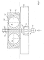
- Fig. 1
- in schematischer Draufsicht von oben die Anbringung einer Stoßleiste an den Füßen zweier nebeneinander stehender Verkaufsmöbel;
- Fig. 2
- eine Vorderansicht der Verkaufsmöbel und der Stoßleiste mit Blick in Richtung II von
Fig. 1 ; und - Fig. 3
- in schematischer Draufsicht von oben zwei Reihen von Verkaufsmöbeln mit in gegenüberliegender Anordnung daran angebrachten Stoßleisten.
- Die Verkaufsmöbel 10, 12 gemäß
Fig. 1 undFig. 2 haben ein Korpus, das auf Rundfüßen 14, 16 ruht. - Die Füße 14, 16 stehen auf einer Fußplatte 18, die aus Metallblech besteht. Die Fußplatte 18 dient zur Verbesserung der Gewichtsverteilung auf den Fußboden und zur Stabilisierung der Verkaufsmöbel 10, 12. Wohlgemerkt kann die Fußplatte 18 auch entfallen.
- Zwischen den nebeneinander stehenden Verkaufsmöbeln 10, 12 verbleibt eine schmale Lücke 20.
- Frontal vor den Füßen 14, 16 der Verkaufsmöbel 10, 12 ist eine Stoßleiste angebracht, die sich aus Verankerungsstücken 22, Eckstücken und/oder Zwischenstücken 24 zusammensetzt. In
Fig. 1 ist nur ein Verankerungsstück 22, und inFig. 2 ein Verankerungsstück 22 mit seitlichen Verbindungselementen 26 gezeigt, die zur Anbringung eines Eck-und/oder Zwischenstücks 24 dienen. - Das Verankerungsstück 22 der Stoßleiste ist an den benachbarten Füßen 14, 16 zweier nebeneinander stehender Verkaufsmöbel 10, 12 angebracht. Hierzu dient ein Bügel, der die Füße 14, 16 hintergreift.
- Der Bügel hat einen ebenen Rücken 28 und abgeschrägte seitliche Flanken 30, 32, deren Neigung abgestuft ist. Die Flanken 30 sind am Bügelrücken 28 flach und weiter außen 32 steiler angestellt.
- Unterhalb der Lücke 20 zwischen den nebeneinander stehenden Verkaufsmöbeln 10, 12 ist mittig zwischen den Füßen 14, 16 eine Gewindestange 34 angeordnet, die an einer Aufschweißmutter 36 mit dem Bügelrücken 28 verschraubt ist. Die Gewindestange 34 ragt durch eine zylindrische Durchgangsbohrung in dem Verankerungsstück 22 nach außen. Am äußeren Ende der Gewindestange 34 sitzt eine Hutmutter 38.
- Die Durchgangsbohrung ist im Durchmesser abgestuft. Sie geht von einer inneren Partie kleineren Durchmessers 40, in der die Gewindestange 34 ein wenig Spiel hat, an einer radialen Stufe 42 in eine äußere Partie größeren Durchmessers über, die eine Aufnahme-Öffnung 44 für die Hutmutter 38 bildet. Die Hutmutter 38 kommt an der Stufe 42 zum Anschlag. Sie liegt dann in der Aufnahme-Öffnung 44 unter die äußere Oberfläche des Verankerungsstücks 22 versenkt. Die Hutmutter 38 ist in der Aufnahme-Öffnung 44 für ein Schraubwerkzeug zugänglich.
- Durch Anziehen der Gewindestange 34 an der Hutmutter 38 wird der Bügel gegen die Füße 14, 16 der Verkaufsmöbel 10, 12 gespannt und das Verankerungsstück 22 an der Frontseite der Füße 14, 16 fixiert.
- Das Verankerungsstück 22 der Stoßleiste ist mit Belüftungsschlitzen 46 versehen. Es kann mit einer nicht näher dargestellten Dichtleiste an die Korpora der Verkaufsmöbel 10, 12 angeschlossen und mit einer weiteren Dichtleiste gegen den Fußboden abgedichtet sein.
- Die in
Fig. 2 gezeigten, seitlichen Verbindungselemente 26 an dem Verankerungsstück 22 sind steckerartig gestaltet. Sie sitzen in passenden Einstecköffnungen des Verankerungsstücks 22 und der daran angerenzenden Eck- und/oder Zwischenstücke 24 der Stoßleiste und sind an Montageöffnungen 48 damit verschraubt. - In der Variante gemäß
Fig. 3 stehen die Verkaufsmöbel 10, 12 in zwei parallelen Reihen einander gegenüber. Die Verkaufsmöbel 10, 12 schlagen jeweils an der Außenseite in Gegenrichtung auf. - Stoßleisten sind wie vor an der Frontseite von zwei benachbarten Füßen 14, 16 nebeneinander stehender Verkaufsmöbel 10, 12 festgespannt. Dazu dienen wiederum Verankerungsstücke 22 mit Gewindestangen 34, die sich mittig zwischen den Füßen 14, 16 unterhalb der Lücke 20 zwischen den nebeneinander stehenden Verkaufsmöbeln 10, 12 erstrecken.
- Mittig zwischen den beiden Reihen von Verkaufsmöbeln 10, 12 sind unterhalb von deren Korpora Gewindestücke 50 angeordnet, in die die Gewindestangen 34 einander gegenüberliegender Verankerungsstücke 22 von der einen bzw. anderen Seite her eingeschraubt sind. Die Gewindestücke 50 sind drehfest und axial verschieblich angeordnet. Bei Anziehen der beiden Gewindestangen 34 werden die Gewindestücke 50 in Gegenrichtung auf Zug beansprucht und die Verankerungsstücke 22 an der Frontseite der Füße 14, 16 fixiert.
- Zwischen den so festgespannten Verankerungsstücken 22 sind in fluchtender Anordnung passende Stoßleisten-Zwischenstücke 24 angebracht.
-
- 10
- Verkaufsmöbel
- 12
- Verkaufsmöbel
- 14
- Fuß
- 16
- Fuß
- 18
- Fußplatte
- 20
- Lücke
- 22
- Verankerungsstück
- 24
- Zwischenstück
- 26
- Verbindungselement
- 28
- Bügelrücken
- 30
- innere Flanke
- 32
- äußere Flanke
- 34
- Gewindestange
- 36
- Aufschweißmutter
- 38
- Hutmutter
- 40
- Partie kleineren Durchmessers
- 42
- Stufe
- 44
- Aufnahme-Öffnung
- 46
- Belüftungsschlitz
- 48
- Montageöffnung
- 50
- Gewindestück
Claims (11)
- Rammschutzvorrichtung für ein Verkaufsmöbel (10, 12), insbesondere Kühl- oder Gefriermöbel, das ein Korpus hat, das auf Füßen (14, 16) ruht, mit einer frontseitig vor den Füßen (14, 16) angeordneten Stoßleiste, die als Abweiser für dagegen anlaufende Einkaufswagen, Flurförderer, Fußbodenreinigungsmaschinen, Besen, Wischmops u.a.m. dient, dadurch gekennzeichnet, daß sich die Stoßleiste aus einem oder mehreren Verankerungsstück(en) (22) und daran angebrachten Eck- und/oder Zwischenstück(en) (24) zusammensetzt, und daß ein Verankerungsstück (22) der Stoßleiste an wenigstens einem Fuß (14, 16) durch Schraubbetätigung einer Gewindestange (34) festspannbar ist, die an dem Fuß (14, 16) vorbei in ein dahinter befindliches Widerlager eingeschraubt ist.
- Rammschutzvorrichtung nach Anspruch 1, dadurch gekennzeichnet, daß ein Verankerungsstück (22) der Stoßleiste an zwei benachbarten Füßen (14, 16) nebeneinander stehender Verkaufsmöbel (10, 12) mittels einer Gewindestange (34) festspannbar ist, die sich zwischen den Füßen (14, 16) hindurch erstreckt.
- Rammschutzvorrichtung nach Anspruch 1 oder 2, dadurch gekennzeichnet, daß die Gewindestange (34) mit einem Schraubenkopf versehen ist, der in einer Öffnung (44) des Verankerungsstücks (22) unter dessen äußere Oberfläche versenkt zu liegen kommt und in der Öffnung (44) für ein Schraubwerkzeug zugänglich ist.
- Rammschutzvorrichtung nach Anspruch 3, dadurch gekennzeichnet, daß der Schraubenkopf eine Hutmutter (38) ist.
- Rammschutzvorrichtung nach einem der Ansprüche 1 bis 4, dadurch gekennzeichnet, daß das Widerlager ein Bügel ist, der die Füße (14, 16) hintergreift.
- Rammschutzvorrichtung nach Anspruch 5, dadurch gekennzeichnet, daß der Bügel einen ebenen Rücken (28) und abgeschrägte seitliche Flanken (30, 32) hat.
- Rammschutzvorrichtung nach Anspruch 6, dadurch gekennzeichnet, daß die Neigung der Flanken (30, 32) abgestuft ist.
- Rammschutzvorrichtung nach Anspruch 7, dadurch gekennzeichnet, daß die Flanken (30) am Bügelrücken (28) flach und weiter außen (32) steiler angestellt sind.
- Rammschutzvorrichtung nach einem der Ansprüche 6 bis 8, dadurch gekennzeichnet, daß die Gewindestange (34) mit dem Bügelrücken (28) verschraubt ist.
- Rammschutzvorrichtung nach Anspruch 9, dadurch gekennzeichnet, daß der Bügelrücken (28) mit einer Aufschweißmutter (36) für die Gewindestange (34) versehen ist.
- Rammschutzvorrichtung nach einem der Ansprüche 1 bis 4, dadurch gekennzeichnet, daß das Widerlager ein Gewindestück (50) ist, in das Gewindestangen (34) einander gegenüberliegender Verankerungsstücke (22) einer Stoßleiste eingeschraubt sind.
Applications Claiming Priority (1)
| Application Number | Priority Date | Filing Date | Title |
|---|---|---|---|
| DE201020010442 DE202010010442U1 (de) | 2010-07-21 | 2010-07-21 | Rammschutzvorrichtung für ein Verkaufsmöbel |
Publications (2)
| Publication Number | Publication Date |
|---|---|
| EP2409601A1 true EP2409601A1 (de) | 2012-01-25 |
| EP2409601B1 EP2409601B1 (de) | 2013-04-10 |
Family
ID=42993970
Family Applications (1)
| Application Number | Title | Priority Date | Filing Date |
|---|---|---|---|
| EP20100013005 Not-in-force EP2409601B1 (de) | 2010-07-21 | 2010-10-01 | Rammschutzvorrichtung für ein Verkaufsmöbel |
Country Status (2)
| Country | Link |
|---|---|
| EP (1) | EP2409601B1 (de) |
| DE (1) | DE202010010442U1 (de) |
Citations (4)
| Publication number | Priority date | Publication date | Assignee | Title |
|---|---|---|---|---|
| AT361431B (de) * | 1978-09-15 | 1981-03-10 | Blomberg Werke Kg | Unterbau mit sockelblende an schrankmoebeln, haushaltsgeraeten od. dgl. |
| DE3047329A1 (de) | 1980-12-16 | 1982-07-15 | Linde Ag, 6200 Wiesbaden | Verkaufskuehlmoebel |
| DE3721420A1 (de) | 1987-06-29 | 1989-01-12 | Linde Ag | Kuehlmoebel |
| US20050087664A1 (en) * | 2003-10-27 | 2005-04-28 | Jeff Ciarlo | Post protector |
-
2010
- 2010-07-21 DE DE201020010442 patent/DE202010010442U1/de not_active Expired - Lifetime
- 2010-10-01 EP EP20100013005 patent/EP2409601B1/de not_active Not-in-force
Patent Citations (4)
| Publication number | Priority date | Publication date | Assignee | Title |
|---|---|---|---|---|
| AT361431B (de) * | 1978-09-15 | 1981-03-10 | Blomberg Werke Kg | Unterbau mit sockelblende an schrankmoebeln, haushaltsgeraeten od. dgl. |
| DE3047329A1 (de) | 1980-12-16 | 1982-07-15 | Linde Ag, 6200 Wiesbaden | Verkaufskuehlmoebel |
| DE3721420A1 (de) | 1987-06-29 | 1989-01-12 | Linde Ag | Kuehlmoebel |
| US20050087664A1 (en) * | 2003-10-27 | 2005-04-28 | Jeff Ciarlo | Post protector |
Also Published As
| Publication number | Publication date |
|---|---|
| EP2409601B1 (de) | 2013-04-10 |
| DE202010010442U1 (de) | 2010-10-21 |
Similar Documents
| Publication | Publication Date | Title |
|---|---|---|
| DE202014105051U1 (de) | Lagerregal | |
| EP2409601A1 (de) | Rammschutzvorrichtung für ein Verkaufsmöbel | |
| DE202005010186U1 (de) | Halteeinrichtung sowie Halteelement hierfür | |
| EP2894258B1 (de) | Rammschutz | |
| DE102010010787B3 (de) | Verbindungsbeschlag für Platteneckverbindungen | |
| EP2476983A2 (de) | Verfahren zur Montage einer Side-by-Side Haushaltsgerätekombination | |
| DE202013009315U1 (de) | Sprinklerschutz | |
| DE3422693C2 (de) | ||
| EP1053700B1 (de) | Untergestell für Tische, Hocker oder dgl. | |
| DE2812142A1 (de) | Vorrichtung zur schnellen befestigung | |
| DE202005007661U1 (de) | Halteeinrichtung sowie Halteelement hierfür | |
| DE1941358C3 (de) | Trägerkonsole zur Halterung einer Glasplatte od.dgl | |
| DE202010010429U1 (de) | Vorrichtung zur Verlängerung eines Möbelfußes eines Möbelstücks | |
| DE19920388A1 (de) | Anordnung zur Herstellung eines Rahmenbauteils sowie Möbelbauteil umfassend ein solches Rahmenbauteil | |
| DE29510388U1 (de) | Rammschutz für einen Fußsockel eines Freiträgerregals | |
| EP3295827B1 (de) | Höhenverstellbare gestellteile für ein möbelstück, insbesondere ein höhenverstellbares tischbein, und höhenverstellbares ein- oder mehrsäulentischgestell | |
| DE4205178C1 (en) | Shelving system with glass or plastics vertical side member - has impact protection with spacer(s) and coupled butting protective member, parallel to and spaced from plinth | |
| DE202015005666U1 (de) | Kupplungsbahnhof für pneumatische Förderanlagen | |
| EP3021038B1 (de) | Arbeitsplatzstehleuchte | |
| DE3232091C1 (de) | Verbindung eines plattenfoermigen Moebelteils mit einer Traverse | |
| DE3914516A1 (de) | Hoehenverstellbares regalsystem | |
| DE1841549U (de) | Regal fuer die zurschausteilung von waren in geschaeften und lagerraumen. | |
| DE202008012034U1 (de) | Vorrichtung zur Verbindung von Gestellen | |
| DE19831858A1 (de) | Verkaufsdisplay | |
| DE19956951A1 (de) | Arbeitsplatzmöbel mit einem Möbelgestell aus vertikalen Säulen und Quertraversen |
Legal Events
| Date | Code | Title | Description |
|---|---|---|---|
| AK | Designated contracting states |
Kind code of ref document: A1 Designated state(s): AL AT BE BG CH CY CZ DE DK EE ES FI FR GB GR HR HU IE IS IT LI LT LU LV MC MK MT NL NO PL PT RO RS SE SI SK SM TR |
|
| AX | Request for extension of the european patent |
Extension state: BA ME |
|
| PUAI | Public reference made under article 153(3) epc to a published international application that has entered the european phase |
Free format text: ORIGINAL CODE: 0009012 |
|
| 17P | Request for examination filed |
Effective date: 20120322 |
|
| GRAP | Despatch of communication of intention to grant a patent |
Free format text: ORIGINAL CODE: EPIDOSNIGR1 |
|
| GRAS | Grant fee paid |
Free format text: ORIGINAL CODE: EPIDOSNIGR3 |
|
| GRAP | Despatch of communication of intention to grant a patent |
Free format text: ORIGINAL CODE: EPIDOSNIGR1 |
|
| GRAA | (expected) grant |
Free format text: ORIGINAL CODE: 0009210 |
|
| AK | Designated contracting states |
Kind code of ref document: B1 Designated state(s): AL AT BE BG CH CY CZ DE DK EE ES FI FR GB GR HR HU IE IS IT LI LT LU LV MC MK MT NL NO PL PT RO RS SE SI SK SM TR |
|
| REG | Reference to a national code |
Ref country code: GB Ref legal event code: FG4D Free format text: NOT ENGLISH |
|
| REG | Reference to a national code |
Ref country code: CH Ref legal event code: EP Ref country code: AT Ref legal event code: REF Ref document number: 605480 Country of ref document: AT Kind code of ref document: T Effective date: 20130415 |
|
| REG | Reference to a national code |
Ref country code: IE Ref legal event code: FG4D Free format text: LANGUAGE OF EP DOCUMENT: GERMAN |
|
| REG | Reference to a national code |
Ref country code: DE Ref legal event code: R096 Ref document number: 502010002892 Country of ref document: DE Effective date: 20130606 |
|
| PG25 | Lapsed in a contracting state [announced via postgrant information from national office to epo] |
Ref country code: SI Free format text: LAPSE BECAUSE OF FAILURE TO SUBMIT A TRANSLATION OF THE DESCRIPTION OR TO PAY THE FEE WITHIN THE PRESCRIBED TIME-LIMIT Effective date: 20130410 |
|
| REG | Reference to a national code |
Ref country code: NL Ref legal event code: VDEP Effective date: 20130410 Ref country code: LT Ref legal event code: MG4D |
|
| REG | Reference to a national code |
Ref country code: CH Ref legal event code: NV Representative=s name: TROESCH SCHEIDEGGER WERNER AG, CH |
|
| PG25 | Lapsed in a contracting state [announced via postgrant information from national office to epo] |
Ref country code: GR Free format text: LAPSE BECAUSE OF FAILURE TO SUBMIT A TRANSLATION OF THE DESCRIPTION OR TO PAY THE FEE WITHIN THE PRESCRIBED TIME-LIMIT Effective date: 20130711 Ref country code: LT Free format text: LAPSE BECAUSE OF FAILURE TO SUBMIT A TRANSLATION OF THE DESCRIPTION OR TO PAY THE FEE WITHIN THE PRESCRIBED TIME-LIMIT Effective date: 20130410 Ref country code: ES Free format text: LAPSE BECAUSE OF FAILURE TO SUBMIT A TRANSLATION OF THE DESCRIPTION OR TO PAY THE FEE WITHIN THE PRESCRIBED TIME-LIMIT Effective date: 20130721 Ref country code: NO Free format text: LAPSE BECAUSE OF FAILURE TO SUBMIT A TRANSLATION OF THE DESCRIPTION OR TO PAY THE FEE WITHIN THE PRESCRIBED TIME-LIMIT Effective date: 20130710 Ref country code: IS Free format text: LAPSE BECAUSE OF FAILURE TO SUBMIT A TRANSLATION OF THE DESCRIPTION OR TO PAY THE FEE WITHIN THE PRESCRIBED TIME-LIMIT Effective date: 20130810 Ref country code: FI Free format text: LAPSE BECAUSE OF FAILURE TO SUBMIT A TRANSLATION OF THE DESCRIPTION OR TO PAY THE FEE WITHIN THE PRESCRIBED TIME-LIMIT Effective date: 20130410 Ref country code: SE Free format text: LAPSE BECAUSE OF FAILURE TO SUBMIT A TRANSLATION OF THE DESCRIPTION OR TO PAY THE FEE WITHIN THE PRESCRIBED TIME-LIMIT Effective date: 20130410 Ref country code: NL Free format text: LAPSE BECAUSE OF FAILURE TO SUBMIT A TRANSLATION OF THE DESCRIPTION OR TO PAY THE FEE WITHIN THE PRESCRIBED TIME-LIMIT Effective date: 20130410 Ref country code: PT Free format text: LAPSE BECAUSE OF FAILURE TO SUBMIT A TRANSLATION OF THE DESCRIPTION OR TO PAY THE FEE WITHIN THE PRESCRIBED TIME-LIMIT Effective date: 20130812 |
|
| PG25 | Lapsed in a contracting state [announced via postgrant information from national office to epo] |
Ref country code: PL Free format text: LAPSE BECAUSE OF FAILURE TO SUBMIT A TRANSLATION OF THE DESCRIPTION OR TO PAY THE FEE WITHIN THE PRESCRIBED TIME-LIMIT Effective date: 20130410 Ref country code: BG Free format text: LAPSE BECAUSE OF FAILURE TO SUBMIT A TRANSLATION OF THE DESCRIPTION OR TO PAY THE FEE WITHIN THE PRESCRIBED TIME-LIMIT Effective date: 20130710 Ref country code: HR Free format text: LAPSE BECAUSE OF FAILURE TO SUBMIT A TRANSLATION OF THE DESCRIPTION OR TO PAY THE FEE WITHIN THE PRESCRIBED TIME-LIMIT Effective date: 20130410 Ref country code: RS Free format text: LAPSE BECAUSE OF FAILURE TO SUBMIT A TRANSLATION OF THE DESCRIPTION OR TO PAY THE FEE WITHIN THE PRESCRIBED TIME-LIMIT Effective date: 20130410 Ref country code: LV Free format text: LAPSE BECAUSE OF FAILURE TO SUBMIT A TRANSLATION OF THE DESCRIPTION OR TO PAY THE FEE WITHIN THE PRESCRIBED TIME-LIMIT Effective date: 20130410 Ref country code: CY Free format text: LAPSE BECAUSE OF FAILURE TO SUBMIT A TRANSLATION OF THE DESCRIPTION OR TO PAY THE FEE WITHIN THE PRESCRIBED TIME-LIMIT Effective date: 20130410 |
|
| PG25 | Lapsed in a contracting state [announced via postgrant information from national office to epo] |
Ref country code: CZ Free format text: LAPSE BECAUSE OF FAILURE TO SUBMIT A TRANSLATION OF THE DESCRIPTION OR TO PAY THE FEE WITHIN THE PRESCRIBED TIME-LIMIT Effective date: 20130410 Ref country code: EE Free format text: LAPSE BECAUSE OF FAILURE TO SUBMIT A TRANSLATION OF THE DESCRIPTION OR TO PAY THE FEE WITHIN THE PRESCRIBED TIME-LIMIT Effective date: 20130410 Ref country code: DK Free format text: LAPSE BECAUSE OF FAILURE TO SUBMIT A TRANSLATION OF THE DESCRIPTION OR TO PAY THE FEE WITHIN THE PRESCRIBED TIME-LIMIT Effective date: 20130410 Ref country code: SK Free format text: LAPSE BECAUSE OF FAILURE TO SUBMIT A TRANSLATION OF THE DESCRIPTION OR TO PAY THE FEE WITHIN THE PRESCRIBED TIME-LIMIT Effective date: 20130410 |
|
| PLBE | No opposition filed within time limit |
Free format text: ORIGINAL CODE: 0009261 |
|
| STAA | Information on the status of an ep patent application or granted ep patent |
Free format text: STATUS: NO OPPOSITION FILED WITHIN TIME LIMIT |
|
| PG25 | Lapsed in a contracting state [announced via postgrant information from national office to epo] |
Ref country code: RO Free format text: LAPSE BECAUSE OF FAILURE TO SUBMIT A TRANSLATION OF THE DESCRIPTION OR TO PAY THE FEE WITHIN THE PRESCRIBED TIME-LIMIT Effective date: 20130410 Ref country code: IT Free format text: LAPSE BECAUSE OF FAILURE TO SUBMIT A TRANSLATION OF THE DESCRIPTION OR TO PAY THE FEE WITHIN THE PRESCRIBED TIME-LIMIT Effective date: 20130410 |
|
| 26N | No opposition filed |
Effective date: 20140113 |
|
| REG | Reference to a national code |
Ref country code: DE Ref legal event code: R097 Ref document number: 502010002892 Country of ref document: DE Effective date: 20140113 |
|
| BERE | Be: lapsed |
Owner name: MENZEL ENERGIESPARSYSTEME G.M.B.H. Effective date: 20131031 |
|
| PG25 | Lapsed in a contracting state [announced via postgrant information from national office to epo] |
Ref country code: MC Free format text: LAPSE BECAUSE OF FAILURE TO SUBMIT A TRANSLATION OF THE DESCRIPTION OR TO PAY THE FEE WITHIN THE PRESCRIBED TIME-LIMIT Effective date: 20130410 |
|
| PG25 | Lapsed in a contracting state [announced via postgrant information from national office to epo] |
Ref country code: BE Free format text: LAPSE BECAUSE OF NON-PAYMENT OF DUE FEES Effective date: 20131031 |
|
| PG25 | Lapsed in a contracting state [announced via postgrant information from national office to epo] |
Ref country code: SM Free format text: LAPSE BECAUSE OF FAILURE TO SUBMIT A TRANSLATION OF THE DESCRIPTION OR TO PAY THE FEE WITHIN THE PRESCRIBED TIME-LIMIT Effective date: 20130410 |
|
| PG25 | Lapsed in a contracting state [announced via postgrant information from national office to epo] |
Ref country code: TR Free format text: LAPSE BECAUSE OF FAILURE TO SUBMIT A TRANSLATION OF THE DESCRIPTION OR TO PAY THE FEE WITHIN THE PRESCRIBED TIME-LIMIT Effective date: 20130410 |
|
| PG25 | Lapsed in a contracting state [announced via postgrant information from national office to epo] |
Ref country code: MK Free format text: LAPSE BECAUSE OF FAILURE TO SUBMIT A TRANSLATION OF THE DESCRIPTION OR TO PAY THE FEE WITHIN THE PRESCRIBED TIME-LIMIT Effective date: 20130410 Ref country code: HU Free format text: LAPSE BECAUSE OF FAILURE TO SUBMIT A TRANSLATION OF THE DESCRIPTION OR TO PAY THE FEE WITHIN THE PRESCRIBED TIME-LIMIT; INVALID AB INITIO Effective date: 20101001 Ref country code: LU Free format text: LAPSE BECAUSE OF NON-PAYMENT OF DUE FEES Effective date: 20131001 |
|
| PG25 | Lapsed in a contracting state [announced via postgrant information from national office to epo] |
Ref country code: MT Free format text: LAPSE BECAUSE OF FAILURE TO SUBMIT A TRANSLATION OF THE DESCRIPTION OR TO PAY THE FEE WITHIN THE PRESCRIBED TIME-LIMIT Effective date: 20130410 |
|
| REG | Reference to a national code |
Ref country code: FR Ref legal event code: PLFP Year of fee payment: 7 |
|
| REG | Reference to a national code |
Ref country code: DE Ref legal event code: R082 Ref document number: 502010002892 Country of ref document: DE Representative=s name: PATENT- UND RECHTSANWAELTE ULLRICH & NAUMANN P, DE |
|
| REG | Reference to a national code |
Ref country code: FR Ref legal event code: PLFP Year of fee payment: 8 |
|
| PGFP | Annual fee paid to national office [announced via postgrant information from national office to epo] |
Ref country code: FR Payment date: 20171023 Year of fee payment: 8 |
|
| PGFP | Annual fee paid to national office [announced via postgrant information from national office to epo] |
Ref country code: IE Payment date: 20171020 Year of fee payment: 8 Ref country code: AT Payment date: 20171018 Year of fee payment: 8 Ref country code: CH Payment date: 20171023 Year of fee payment: 8 Ref country code: GB Payment date: 20171024 Year of fee payment: 8 |
|
| PG25 | Lapsed in a contracting state [announced via postgrant information from national office to epo] |
Ref country code: AL Free format text: LAPSE BECAUSE OF FAILURE TO SUBMIT A TRANSLATION OF THE DESCRIPTION OR TO PAY THE FEE WITHIN THE PRESCRIBED TIME-LIMIT Effective date: 20130410 |
|
| PGFP | Annual fee paid to national office [announced via postgrant information from national office to epo] |
Ref country code: DE Payment date: 20181214 Year of fee payment: 9 |
|
| REG | Reference to a national code |
Ref country code: CH Ref legal event code: PL |
|
| REG | Reference to a national code |
Ref country code: AT Ref legal event code: MM01 Ref document number: 605480 Country of ref document: AT Kind code of ref document: T Effective date: 20181001 |
|
| GBPC | Gb: european patent ceased through non-payment of renewal fee |
Effective date: 20181001 |
|
| REG | Reference to a national code |
Ref country code: IE Ref legal event code: MM4A |
|
| PG25 | Lapsed in a contracting state [announced via postgrant information from national office to epo] |
Ref country code: FR Free format text: LAPSE BECAUSE OF NON-PAYMENT OF DUE FEES Effective date: 20181031 Ref country code: CH Free format text: LAPSE BECAUSE OF NON-PAYMENT OF DUE FEES Effective date: 20181031 Ref country code: LI Free format text: LAPSE BECAUSE OF NON-PAYMENT OF DUE FEES Effective date: 20181031 |
|
| PG25 | Lapsed in a contracting state [announced via postgrant information from national office to epo] |
Ref country code: IE Free format text: LAPSE BECAUSE OF NON-PAYMENT OF DUE FEES Effective date: 20181001 Ref country code: AT Free format text: LAPSE BECAUSE OF NON-PAYMENT OF DUE FEES Effective date: 20181001 Ref country code: GB Free format text: LAPSE BECAUSE OF NON-PAYMENT OF DUE FEES Effective date: 20181001 |
|
| REG | Reference to a national code |
Ref country code: DE Ref legal event code: R119 Ref document number: 502010002892 Country of ref document: DE |
|
| PG25 | Lapsed in a contracting state [announced via postgrant information from national office to epo] |
Ref country code: DE Free format text: LAPSE BECAUSE OF NON-PAYMENT OF DUE FEES Effective date: 20200501 |