EP2409367B1 - Presse de sertissage - Google Patents
Presse de sertissage Download PDFInfo
- Publication number
- EP2409367B1 EP2409367B1 EP10709530.9A EP10709530A EP2409367B1 EP 2409367 B1 EP2409367 B1 EP 2409367B1 EP 10709530 A EP10709530 A EP 10709530A EP 2409367 B1 EP2409367 B1 EP 2409367B1
- Authority
- EP
- European Patent Office
- Prior art keywords
- projection
- retaining
- adapter
- base plate
- groove
- Prior art date
- Legal status (The legal status is an assumption and is not a legal conclusion. Google has not performed a legal analysis and makes no representation as to the accuracy of the status listed.)
- Active
Links
Images
Classifications
-
- H—ELECTRICITY
- H01—ELECTRIC ELEMENTS
- H01R—ELECTRICALLY-CONDUCTIVE CONNECTIONS; STRUCTURAL ASSOCIATIONS OF A PLURALITY OF MUTUALLY-INSULATED ELECTRICAL CONNECTING ELEMENTS; COUPLING DEVICES; CURRENT COLLECTORS
- H01R43/00—Apparatus or processes specially adapted for manufacturing, assembling, maintaining, or repairing of line connectors or current collectors or for joining electric conductors
- H01R43/04—Apparatus or processes specially adapted for manufacturing, assembling, maintaining, or repairing of line connectors or current collectors or for joining electric conductors for forming connections by deformation, e.g. crimping tool
- H01R43/048—Crimping apparatus or processes
-
- B—PERFORMING OPERATIONS; TRANSPORTING
- B21—MECHANICAL METAL-WORKING WITHOUT ESSENTIALLY REMOVING MATERIAL; PUNCHING METAL
- B21D—WORKING OR PROCESSING OF SHEET METAL OR METAL TUBES, RODS OR PROFILES WITHOUT ESSENTIALLY REMOVING MATERIAL; PUNCHING METAL
- B21D37/00—Tools as parts of machines covered by this subclass
- B21D37/04—Movable or exchangeable mountings for tools
-
- B—PERFORMING OPERATIONS; TRANSPORTING
- B30—PRESSES
- B30B—PRESSES IN GENERAL
- B30B15/00—Details of, or accessories for, presses; Auxiliary measures in connection with pressing
- B30B15/02—Dies; Inserts therefor; Mounting thereof; Moulds
- B30B15/026—Mounting of dies, platens or press rams
Definitions
- the invention relates to a crimping press according to the preamble of claim 1.
- Such a crimping press is from the DE 10 2006 041 846 B3 known. It comprises a clamping plate, a crimping tool with a base plate, which are rigidly connected during normal use. An adapter is connected to the base plate by means of first holding claws without rigid contact and relatively movably in order to achieve vibration isolation with respect to a memory fixed thereto for the crimp contacts to be processed.
- the assignment of the base plate to the clamping plate after a tool change is not always as accurate as is desirable. The crimping result can be adversely affected.
- the invention is based on the object of further developing such a crimping press in such a way that an accurate and exactly reproducible positioning of the crimping tool in the crimping apparatus can be achieved even with frequent tool changes.
- the adapter for solving this problem is provided at one end with an I - projection and fixed immovably to the base plate with the aid of the first holding claws in the region of the I - projection, wherein the I - projection parallel to its longitudinal direction in a one side in the longitudinal direction and in the direction of the base plate open groove of the clamping plate is inserted, wherein the I - projection in the direction of the base plate has a lower height than the groove, wherein the I - projection a centrally mounted recess having a parallel to the longitudinal direction in the recess projecting retaining cams, wherein the retaining cam with at least a second retaining claw of the clamping plate is engageable and wherein the base plate is pressed by the second retaining claw on both sides of the groove directly to the platen.
- the adapter thereby fulfills the purpose to position the base plate very accurately with respect to the platen and to press directly adjacent to each other while avoiding intermediate layers. Both in the horizontal direction as well as in the vertical position, this results in a very accurate and reproducible positioning of the crimping tool in the crimping press, which contributes significantly to avoid adjustment work even after a tool change and immediately achieve a perfect crimping result.
- a particularly firm, vertical compression of the clamping plate and the base plate can be obtained when the retaining cam is provided with a clamping surface arranged inclined to the plane of the platen, wherein the second retaining claw is movable parallel to the plane of the clamping plate and engageable with the inclined clamping surface.
- the clamping surface is suitably positioned within one of three imaginary, straight connecting lines of the first retaining claws enclosed field, which connect the I-projection with the base plate.
- the retaining cam can thus be particularly stable statically to the mutual contact surfaces of the base plate and the clamping plate to press together.
- the profile of the I - projection and the profile of the groove should correspond to each other as far as possible with good Relativverschieb sadness.
- the lateral flank surfaces of the I - projection and the groove should touch each other for this purpose displaced play.
- the I - projection and the groove may be formed at the end facing the adapter 1.5 to 2 times as wide as at the projecting end.
- the insertion of the I - projection in the longitudinal direction of the groove is facilitated.
- the tilting security is improved with respect to the during the intended use with the I - pressed projection batten, which makes it easier to use the adapter for attaching secondary items, such as memories for crimp contacts or similar.
- the regions of different width of the I - projection and the groove by at least one inclined surface inclined to be connected in transition.
- the I - projection and the groove are exactly adapted to each other in terms of shape and size, so that they are easily but shakeproof and play-free inserted into each other. Only in the vertical direction, the groove is higher than the I - projection.
- the I - projection may be extended at the end facing the adapter to a transverse web, wherein two of the first retaining claws respectively the front end of the transverse web, according to facing forward, overlap above and at least a third retaining claw, the front end of the I - projecting, turned backwards, overlaps above. It is expedient to arrange only a single, first holding claw at the front end of the I projection. This first retaining claw can be displaceable by a clamping screw in the direction of the other holding claws and be brought into engagement with the associated inclined clamping surfaces of the base plate in order to grasp this forceps like the front and rear end and set immovable.
- the adapter can be extended to a holder for secondary elements at the end remote from the I - projection. If vibrations can be excited by such secondary elements during the intended use, there is the possibility that the holder and the adapter are connected vibration-isolated. This can be done, for example, that the holder and the adapter during the intended use of the crimping press outside the clamping area of the crimping tool without direct mutual contact loosely connected and are supported completely independent of each other. Secondary elements that tend to generate natural vibrations, during the intended use of the crimping press can also be completely separated from the holder and thus the adapter, in which the loose connection is temporarily canceled.
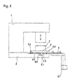
- Fig. 1 shows an exemplary embodiment of the crimping press 1 according to the invention in a schematic representation of the side and with a crimping tool 3 inserted therein.
- the crimping press 1 comprises a clamping plate 2, a crimping tool 3 with a base plate 4 and an adapter 5.
- the adapter 5 can be fixed releasably under the base plate 4 with the aid of first retaining claws 5.2.
- three first retaining claws 5.2 are provided ( Fig. 2 ).
- the adapter 5 is at one end with a in plan view ( Fig. 2 ) Provided I - shaped projection 5.1 and with the help of the first retaining claws 5.2 immovably fixed to the base plate 4 by the retaining claws 5.2 cooperate like a pincers.
- the I - projection 5.1 is parallel to its longitudinal direction laterally backlash inserted into a groove 2.2 of the platen 2.
- the groove 2.2 is one-sided in the longitudinal direction and open in the direction of the base plate 4.
- the I - projection 5.1 has a lower height in the direction of the base plate 4 than the groove 2.2.
- the I - projection 5.1 has a centrally mounted recess or opening 5.3 ( Fig. 2 ) with a parallel to the longitudinal direction in the recess projecting retaining cam 5.4 ( Fig. 1 . 3) on.
- the retaining cam 5.4 can be brought into engagement with at least one second retaining claw 2.1 of the clamping plate 2 and the base plate 4 can be pressed by the second retaining claw 2.1 on both sides of the groove 2.2 directly to the clamping plate 2.
- the adapter 5 is fixed immovably to the base plate 4 and the platen 2, by the retaining claw 2.1 and the play-free insertion of the I - projection 5.1 parallel to its longitudinal direction and in the transverse direction in the groove 2.2 of the platen 2.
- the insertion is followed by a pliers against each other directed displacement of the first retaining claws 5.2.
- first retaining claws 5.2 can be inserted into recesses of the base plate 4, which are open in the joining direction and dimensioned and mounted so that an exact positioning of the I - protrusion 5.1 also results in the transverse direction with respect to the base plate 4.
- first retaining claws 5.2 When clamping the base plate 4 with acute angled inclined clamping surfaces of the base plate 4 in Intervention to ensure a particularly intensive mutual compression in the vertical direction and thus a rigid mutual association.
- the first retaining claw 5.2 attached to the front end of the I projection 5.1 and the first retaining claws 5.2 attached to the rear end have a forceps-like, opposite direction of action.
- I - projection 5.1 retaining cam 5.4 is provided with a tilted to the plane of the platen 2 arranged clamping surface 5.5 ( Fig. 3 ), wherein only the second retaining claw 2.1 of the platen 2 is movable parallel to its longitudinal direction and engageable with the clamping surface 5.5 in engagement.
- a good and very accurate positioning of the I - projection 5.1 of the adapter 5 with respect to the platen 2 is achieved in the longitudinal direction of the groove and a very precise and rigid mutual assignment in the vertical and horizontal directions.
- the adapter 5 is extended at the end facing away from the I - projection 5.1 end to a holder 5.7 for secondary elements, such as a memory for Crimpcardario.
- secondary elements such as a memory for CrimpCountario.
- Such crimp contact elements consist of stampings of metal, which are usually wound into a coil and tend to snag on the coil with their protruding parts into each other and to produce unbalances in unwinding. When unwinding in a crimping device, this can lead to vibrations that adversely affect the crimping result.
- the holder 5.7 and the adapter 5 are therefore vibration-isolated connected in the embodiment shown here by screw heads of the holder 5.7, which are received with horizontal and vertical play in holes in the adapter 5.
- the holder is designed as an autonomous floor vehicle and provided with rollers. He serves to process the and to supply crimping press 1 wound on rolls as a continuous belt as needed to the crimping press 1.
- the crimping tool 3 required for this purpose can remain on the ground vehicle. It is then fixed to the adapter. The loose connection between the adapter 5 and the ground vehicle is not a hindrance during storage, because yes both parts are still connected to each other captive. Commissioning is still very easy.
- the floor vehicle with the crimp contacts and the crimping tool 3 loosely attached thereto via the adapter 5 is rolled to the crimping press 1.
- the adapter 5 is introduced there with the connected crimping tool 3 in the groove 2.2 of the clamping plate 2 without play and fixed by operating the claw 2.1 immovable therein.
- the one-sided and asymmetrically mounted inclined surface 5.9 serves as a stop in the longitudinal direction. Since the height of the projection 5.1 in the direction of the base plate 4 is less than that of the groove 2.2, the adapter 5 is pulled down upon actuation of the retaining claw 2.1 until the base plate 4 rests on the clamping plate 2.
- the first retaining claws 5.2 can give something due to their construction.
- connection via the screw 5.8 can also be spring-loaded.
- a mushroom projection which is arranged at the upper end of the crimping die of the crimping tool 3, parallel to the insertion of the I-projection of the adapter 5 into the groove in a double-T-groove of the crimping press 3.
- the vertical up and down movements of the press ram of the crimping press 3 can thereby be transferred to the crimping punch and thus to the crimping tool 3 and crimping operations can be performed without the movements being transmitted directly to the I-protrusion.
- the weight of the crimp contacts is meanwhile supported by the holder 5.7 independent of the crimping tool 3 vibration-insulated on the ground. uneven Unwinding of the crimp contacts can therefore not lead to a disturbance of the crimping process.
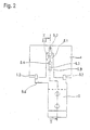
- Fig. 2 shows the assignment of the adapter 5 to the base plate 4 in a view from above.
- the second holding claw (2.1 in Fig. 1 and 3 ) of the clamping plate 2 is positioned within one of three imaginary, straight connecting lines of the first retaining claws 5.2 enclosed triangular field, which connect the I - projection 5.1 with the base plate 4. This ensures that the I - projection 5.1 passes consistently and non-tilting into a good contact with the bottom of the base plate 4. He is in turn inserted laterally and in the longitudinal direction without play in the groove 2.2 of the clamping plate 2 and connected by the retaining claw 2.1 rigid and in a precisely predetermined position before.
- the retaining claws 5.2, 2.1 reach in all sub-areas with inclined clamping surfaces in engagement with the plane of the platen 4 include an angle of 20 to 40 ° in order to achieve good reliable connection of the connection reliable, vertical compression of the respective parts to be pressed.
- the I - projection 5.1 touches the lateral flank surfaces 5.9 of the groove 2.2 without play fitting and yet easily displaced to achieve the most accurate mutual assignment in the transverse direction.
- the I - projection 5.1 and the groove 2.2 are at the end facing the adapter 5 1.6 times as wide as at the projecting end to improve the tilting security between the adapter 5 and the base plate 4 fixed thereto.
- the areas of different width of the I - projection 5.1 and the groove 4.1 are connected by the one-sided and asymmetrically mounted inclined surface 5.9.
- the I - projection 5.1 is extended at the end facing away from the adapter 5 to a crosspiece 5.6, wherein the two first retaining claws 5.2 overlap on the one hand adjacent to each other, the front end of the crosspiece 5.6 above. Centrally opposite to these retaining claws, individual first retaining claw 5.2 is arranged at the front end of the I projection 5.1. Based on the base plate 4, the first retaining claws 5.2 are thus distributed distributed on the floor plan of a triangle that surrounds the second retaining claw 2.1 at a distance. The second retaining claw 2.1 causes a vertical and horizontal compression of the base plate 4 with the clamping plate. 2
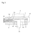
- Fig. 3 shows an inserted into the space between a platen 2 and a base plate 4 adapter 5 schematically and in longitudinal section.
- the I - projection 5.1 of the adapter 5 is connected by the tong-like co-operating, first retaining claws 5.2 on inclined clamping surfaces with the base plate 4 and fixed in counterpressure immovable and accurately positioned thereto.
- the reproduced in the left part of the illustration holding claw 5.2 is parallel to the longitudinal direction of the platen 4 attached to the I - 5.1 projection and slidable by a clamping screw 5.8 to the right and with the inclined clamping surface engageable. This results in that the base plate 4 is pushed with the attached on the right side inclined surfaces under the holding claws located there 5.2 with the result that it comes to a total vertical compression of the adapter 5 with the base plate 4.
- the I - projection 5.1 of the adapter 5 includes a centrally disposed aperture with a retaining cam 5.4, which is also limited on the base plate 4 side facing by the inclined clamping surface 5.5.
- a second retaining claw 2.1 of the clamping plate 2 With the clamping surface is a second retaining claw 2.1 of the clamping plate 2 into engagement, which is displaceable in the direction of the arrow entered in the drawing.
- the in the groove engaging I - projection 5.1 of the adapter 5 has a smaller depth than the groove.
- a relative displacement of the second retaining claw 2.1 in the direction of the arrow therefore has a vertical compression of the laterally adjacent to the groove areas of the clamping plate 2 and the base plate 4 and as a result of a rigid fixing of the two parts together. Parallel to this results in a displacement of the adapter 5 in the longitudinal direction of the groove 4.1 forward until a rigidly predetermined, reproducible end position is reached.
Claims (12)
- Presse de sertissage (1) comprenant une plaque de serrage (2), un outil de sertissage (3) avec une plaque de base (4) et un adaptateur (5) pouvant être fixé de manière amovible sur la face inférieure de la plaque de base (4) au moyen de premières griffes de maintien (5.2), caractérisée en ce que l'adaptateur (5) est pourvu d'une saillie en I (5.1) à une extrémité et peut être totalement immobilisé contre la plaque de base (4) au moyen des premières griffes de maintien (5.2), en ce que la saillie en I (5.1) peut être insérée parallèlement à sa direction longitudinale dans une rainure (2.2) de la plaque de serrage (2) ouverte sur un côté dans la direction longitudinale et dans la direction de la plaque de base (4), en ce que la saillie en I (5.1) présente dans la direction de la plaque de base (4) une hauteur inférieure à celle de la rainure (2.2), en ce que la saillie en I (5.1) comporte un évidement (5.3) ménagé centralement avec une came de maintien (5.4) rentrant dans l'évidement parallèlement à la direction longitudinale, en ce que la came de maintien (5.4) peut être engrenée avec au moins une deuxième griffe de maintien (2.1) de la plaque de serrage (2), et en ce que la plaque de base (4) peut être serrée directement contre la plaque de serrage (2) par la deuxième griffe de maintien (2.1) de part et d'autre de la rainure (2.2).
- Presse de sertissage selon la revendication 1, caractérisée en ce que la came de maintien (5.4) comporte une surface de serrage (5.5) inclinée par rapport au plan de la plaque de serrage (2), et en ce que la deuxième griffe de maintien (2.1) est déplaçable parallèlement au plan de la plaque de serrage (2) et peut être engrenée avec la surface de serrage (5.5).
- Presse de sertissage selon la revendication 2, caractérisée en ce que la deuxième griffe de maintien (2.1) positionne la surface de serrage (5.5) à l'intérieur d'un champ entouré par trois lignes de connexion théoriques droites des premières griffes de maintien (5.2), lesquelles relient la saillie en I (5.1) à la plaque de base (4).
- Presse de sertissage selon l'une des revendications 1 à 3, caractérisée en ce que la surface de serrage (5.5) et le plan de la plaque de serrage (4) forment un angle compris entre 20 et 40°.
- Presse de sertissage selon l'une des revendications 1 à 4, caractérisée en ce que la saillie en I (5.1) contacte par déplacement les surfaces de flanc latérales de la rainure (4.1).
- Presse de sertissage selon l'une des revendications 1 à 5, caractérisée en ce que la saillie en I (5.1) et la rainure (4.1) sont de 1,5 à 2 fois plus larges à l'extrémité opposée à l'adaptateur (5) qu'à l'extrémité en saillie.
- Presse de sertissage selon la revendication 6, caractérisée en ce que les parties de largeurs différentes de la saillie en I (5.1) et de la rainure (4.1) sont reliées par au moins une surface oblique (5.7).
- Presse de sertissage selon l'une des revendications 4 à 7, caractérisée en ce que la saillie en I (5.1) s'élargit en formant une traverse (5.6) à l'extrémité distante de l'adaptateur (5), et en ce que les premières griffes de maintien (5.2) sont respectivement disposées à l'extrémité avant de la traverse (5.6) et de la saillie en I (5.1).
- Presse de sertissage selon l'une des revendications 1 à 8, caractérisée en ce que l'adaptateur (5) est prolongé en formant un support (5.7) pour des éléments secondaires à l'extrémité distante de la saillie en I (5.1).
- Presse de sertissage selon la revendication 9, caractérisée en ce que le support (5.7) et l'adaptateur (5) sont raccordés en étant isolés contre les vibrations.
- Presse de sertissage selon l'une des revendications 1 à 10, caractérisée en ce que la saillie en I (5.1) de l'adaptateur (5) est insérable sans jeu dans la rainure (2.2) dans la direction latérale.
- Convoyeur autonome au sol pour l'amenée de contacts à sertir enroulés sur une bobine vers une presse de sertissage selon l'une des revendications précédentes, avec un adaptateur (5) pourvu d'une saillie en I (5.1) à une extrémité et de premières griffes de maintien (5.2), la saillie en I (5.1) comportant un évidement (5.3) ménagé centralement avec une came de maintien (5.4) rentrant dans l'évidement parallèlement à la direction longitudinale, de telle manière que la came de maintien (5.4) peut être engrenée avec au moins une deuxième griffe de maintien (2.1).
Priority Applications (1)
| Application Number | Priority Date | Filing Date | Title |
|---|---|---|---|
| PL10709530T PL2409367T3 (pl) | 2009-03-18 | 2010-03-18 | Prasa do zagniatania |
Applications Claiming Priority (3)
| Application Number | Priority Date | Filing Date | Title |
|---|---|---|---|
| DE102009013775 | 2009-03-18 | ||
| DE102009031051A DE102009031051B9 (de) | 2009-03-18 | 2009-06-30 | Crimppresse |
| PCT/EP2010/053578 WO2010106151A1 (fr) | 2009-03-18 | 2010-03-18 | Presse de sertissage |
Publications (2)
| Publication Number | Publication Date |
|---|---|
| EP2409367A1 EP2409367A1 (fr) | 2012-01-25 |
| EP2409367B1 true EP2409367B1 (fr) | 2013-05-01 |
Family
ID=42664175
Family Applications (1)
| Application Number | Title | Priority Date | Filing Date |
|---|---|---|---|
| EP10709530.9A Active EP2409367B1 (fr) | 2009-03-18 | 2010-03-18 | Presse de sertissage |
Country Status (5)
| Country | Link |
|---|---|
| EP (1) | EP2409367B1 (fr) |
| DE (1) | DE102009031051B9 (fr) |
| ES (1) | ES2423027T3 (fr) |
| PL (1) | PL2409367T3 (fr) |
| WO (1) | WO2010106151A1 (fr) |
Cited By (1)
| Publication number | Priority date | Publication date | Assignee | Title |
|---|---|---|---|---|
| CN111740292A (zh) * | 2020-08-07 | 2020-10-02 | 南昌冠东科技有限公司 | 自动调节式端子压接机 |
Families Citing this family (2)
| Publication number | Priority date | Publication date | Assignee | Title |
|---|---|---|---|---|
| CN103414083A (zh) * | 2013-07-24 | 2013-11-27 | 昆山迈致治具科技有限公司 | 一种可开合导线装针治具 |
| CN105337571A (zh) * | 2015-09-30 | 2016-02-17 | 苏州索力旺新能源科技有限公司 | 一种导电片铆接导线凹槽冲压机 |
Family Cites Families (5)
| Publication number | Priority date | Publication date | Assignee | Title |
|---|---|---|---|---|
| US4611484A (en) * | 1984-12-10 | 1986-09-16 | Amp Incorporated | Quick change mounting plate |
| FR2643514B1 (fr) * | 1989-02-17 | 1991-10-25 | Ricard Claude | Procedes et dispositifs pour sertir mecaniquement une piece de connexion sur un fil |
| FR2749797B1 (fr) * | 1996-06-12 | 1998-09-04 | Sierma Ingenierie | Dispositif de sertissage en series de cosses metalliques et cassette d'outils |
| DE29919482U1 (de) * | 1999-11-05 | 2000-01-20 | Grote & Hartmann | Hubwerkzeugvorrichtung, insbesondere Crimpwerkzeugvorrichtung |
| DE102006041846B3 (de) * | 2006-09-06 | 2007-12-27 | Schäfer Werkzeug- und Sondermaschinenbau GmbH | Crimpvorrichtung |
-
2009
- 2009-06-30 DE DE102009031051A patent/DE102009031051B9/de not_active Expired - Fee Related
-
2010
- 2010-03-18 EP EP10709530.9A patent/EP2409367B1/fr active Active
- 2010-03-18 PL PL10709530T patent/PL2409367T3/pl unknown
- 2010-03-18 ES ES10709530T patent/ES2423027T3/es active Active
- 2010-03-18 WO PCT/EP2010/053578 patent/WO2010106151A1/fr active Application Filing
Cited By (2)
| Publication number | Priority date | Publication date | Assignee | Title |
|---|---|---|---|---|
| CN111740292A (zh) * | 2020-08-07 | 2020-10-02 | 南昌冠东科技有限公司 | 自动调节式端子压接机 |
| CN111740292B (zh) * | 2020-08-07 | 2021-05-25 | 江苏友孚汽车部件科技有限公司 | 自动调节式端子压接机 |
Also Published As
| Publication number | Publication date |
|---|---|
| DE102009031051B9 (de) | 2013-01-31 |
| WO2010106151A1 (fr) | 2010-09-23 |
| PL2409367T3 (pl) | 2013-09-30 |
| DE102009031051B4 (de) | 2012-11-29 |
| EP2409367A1 (fr) | 2012-01-25 |
| ES2423027T3 (es) | 2013-09-17 |
| DE102009031051A1 (de) | 2010-09-30 |
Similar Documents
| Publication | Publication Date | Title |
|---|---|---|
| DE2704540C2 (fr) | ||
| DE3347323A1 (de) | Magazinschrauber | |
| DE1615840A1 (de) | Einstellbares Quetschwerkzeug | |
| EP0039949A2 (fr) | Dispositif pour alimenter automatiquement en vis | |
| DE102014016630A1 (de) | Verstelleinrichtung für eine Druckrolle einer Bearbeitungsmaschine, insbesondere Kehlmaschine, sowie Bearbeitsmaschine, insbesondere Kehlmaschine, mit einer solchen Verstelleinrichtung | |
| EP2883658B1 (fr) | Accessoire pour un dispositif de presse | |
| DE4100327A1 (de) | Montagevorrichtung eines schuhs auf einem ski | |
| EP2409367B1 (fr) | Presse de sertissage | |
| DE2141767C2 (de) | Vorrichtung zum Stechen von Langlöchern in ein rohrförmiges Bauteil | |
| EP2233626B1 (fr) | Aide à l'introduction destinée au garnissage de planches à pointes | |
| EP1245860B1 (fr) | Dispositif de fixation d'agrafes de jonction de courroie à des courroies transporteuses | |
| DE4422076C2 (de) | Bindungseinrichtung zwischen einem Schuh und einem Sportgerät, insbesondere Schibindung | |
| EP3144076A1 (fr) | Outil pour une poinçonneuse pour transformer des sections d'une piece usinee en forme de plaque et procede associe | |
| CH656544A5 (de) | Vorrichtung zur laengsverstellung von skibindungsteilen. | |
| DE3939664A1 (de) | Steckzungenanordnung | |
| EP3257619B1 (fr) | Magasin pour vis | |
| DE19946122A1 (de) | Greifer einer heb- und senkbaren Aufnahmevorrichtung für von oben zu greifende Behälter | |
| DE3108437C2 (de) | Vorrichtung zum Montieren von Einbaudosen für Elektroinstallation | |
| DE19855711C2 (de) | Vorrichtung zur Befestigung von Wirkelementen an der Barre einer Kettenwirkmaschine | |
| EP2233039B1 (fr) | Guidage pour tiroirs | |
| DE10035427B4 (de) | Vorrichtung zum Eindrücken von Schrauben | |
| EP3240103A1 (fr) | Support de poteau et procédé de montage d'un support de poteau | |
| DE2824301C2 (de) | Vorrichtung zum Verbinden eines Fensterblend- oder eines Türrahmens mit einem Rolladenkasten | |
| DE3309475A1 (de) | Vorrichtung zur befestigung von halteklipsen fuer heizungsrohre an fussbodenheizungselementen | |
| DE19513483A1 (de) | Verfahren und Vorrichtung zum Befestigen von Verbindungselementen an den Enden von Gurten, insbesondere von Fördergurten |
Legal Events
| Date | Code | Title | Description |
|---|---|---|---|
| PUAI | Public reference made under article 153(3) epc to a published international application that has entered the european phase |
Free format text: ORIGINAL CODE: 0009012 |
|
| 17P | Request for examination filed |
Effective date: 20111012 |
|
| AK | Designated contracting states |
Kind code of ref document: A1 Designated state(s): AT BE BG CH CY CZ DE DK EE ES FI FR GB GR HR HU IE IS IT LI LT LU LV MC MK MT NL NO PL PT RO SE SI SK SM TR |
|
| DAX | Request for extension of the european patent (deleted) | ||
| GRAP | Despatch of communication of intention to grant a patent |
Free format text: ORIGINAL CODE: EPIDOSNIGR1 |
|
| GRAS | Grant fee paid |
Free format text: ORIGINAL CODE: EPIDOSNIGR3 |
|
| GRAA | (expected) grant |
Free format text: ORIGINAL CODE: 0009210 |
|
| AK | Designated contracting states |
Kind code of ref document: B1 Designated state(s): AT BE BG CH CY CZ DE DK EE ES FI FR GB GR HR HU IE IS IT LI LT LU LV MC MK MT NL NO PL PT RO SE SI SK SM TR |
|
| REG | Reference to a national code |
Ref country code: GB Ref legal event code: FG4D Free format text: NOT ENGLISH |
|
| REG | Reference to a national code |
Ref country code: CH Ref legal event code: NV Representative=s name: SCHNEIDER FELDMANN AG PATENT- UND MARKENANWAEL, CH Ref country code: CH Ref legal event code: EP Ref country code: AT Ref legal event code: REF Ref document number: 610441 Country of ref document: AT Kind code of ref document: T Effective date: 20130515 |
|
| REG | Reference to a national code |
Ref country code: IE Ref legal event code: FG4D Free format text: LANGUAGE OF EP DOCUMENT: GERMAN |
|
| REG | Reference to a national code |
Ref country code: DE Ref legal event code: R096 Ref document number: 502010003158 Country of ref document: DE Effective date: 20130627 |
|
| REG | Reference to a national code |
Ref country code: RO Ref legal event code: EPE |
|
| REG | Reference to a national code |
Ref country code: ES Ref legal event code: FG2A Ref document number: 2423027 Country of ref document: ES Kind code of ref document: T3 Effective date: 20130917 |
|
| REG | Reference to a national code |
Ref country code: PL Ref legal event code: T3 |
|
| REG | Reference to a national code |
Ref country code: NL Ref legal event code: VDEP Effective date: 20130501 |
|
| REG | Reference to a national code |
Ref country code: LT Ref legal event code: MG4D |
|
| PG25 | Lapsed in a contracting state [announced via postgrant information from national office to epo] |
Ref country code: IS Free format text: LAPSE BECAUSE OF FAILURE TO SUBMIT A TRANSLATION OF THE DESCRIPTION OR TO PAY THE FEE WITHIN THE PRESCRIBED TIME-LIMIT Effective date: 20130901 Ref country code: FI Free format text: LAPSE BECAUSE OF FAILURE TO SUBMIT A TRANSLATION OF THE DESCRIPTION OR TO PAY THE FEE WITHIN THE PRESCRIBED TIME-LIMIT Effective date: 20130501 Ref country code: PT Free format text: LAPSE BECAUSE OF FAILURE TO SUBMIT A TRANSLATION OF THE DESCRIPTION OR TO PAY THE FEE WITHIN THE PRESCRIBED TIME-LIMIT Effective date: 20130902 Ref country code: SE Free format text: LAPSE BECAUSE OF FAILURE TO SUBMIT A TRANSLATION OF THE DESCRIPTION OR TO PAY THE FEE WITHIN THE PRESCRIBED TIME-LIMIT Effective date: 20130501 Ref country code: SI Free format text: LAPSE BECAUSE OF FAILURE TO SUBMIT A TRANSLATION OF THE DESCRIPTION OR TO PAY THE FEE WITHIN THE PRESCRIBED TIME-LIMIT Effective date: 20130501 Ref country code: NO Free format text: LAPSE BECAUSE OF FAILURE TO SUBMIT A TRANSLATION OF THE DESCRIPTION OR TO PAY THE FEE WITHIN THE PRESCRIBED TIME-LIMIT Effective date: 20130801 Ref country code: LT Free format text: LAPSE BECAUSE OF FAILURE TO SUBMIT A TRANSLATION OF THE DESCRIPTION OR TO PAY THE FEE WITHIN THE PRESCRIBED TIME-LIMIT Effective date: 20130501 Ref country code: GR Free format text: LAPSE BECAUSE OF FAILURE TO SUBMIT A TRANSLATION OF THE DESCRIPTION OR TO PAY THE FEE WITHIN THE PRESCRIBED TIME-LIMIT Effective date: 20130802 |
|
| PG25 | Lapsed in a contracting state [announced via postgrant information from national office to epo] |
Ref country code: BG Free format text: LAPSE BECAUSE OF FAILURE TO SUBMIT A TRANSLATION OF THE DESCRIPTION OR TO PAY THE FEE WITHIN THE PRESCRIBED TIME-LIMIT Effective date: 20130801 Ref country code: HR Free format text: LAPSE BECAUSE OF FAILURE TO SUBMIT A TRANSLATION OF THE DESCRIPTION OR TO PAY THE FEE WITHIN THE PRESCRIBED TIME-LIMIT Effective date: 20130501 Ref country code: CY Free format text: LAPSE BECAUSE OF FAILURE TO SUBMIT A TRANSLATION OF THE DESCRIPTION OR TO PAY THE FEE WITHIN THE PRESCRIBED TIME-LIMIT Effective date: 20130501 |
|
| PG25 | Lapsed in a contracting state [announced via postgrant information from national office to epo] |
Ref country code: LV Free format text: LAPSE BECAUSE OF FAILURE TO SUBMIT A TRANSLATION OF THE DESCRIPTION OR TO PAY THE FEE WITHIN THE PRESCRIBED TIME-LIMIT Effective date: 20130501 |
|
| PG25 | Lapsed in a contracting state [announced via postgrant information from national office to epo] |
Ref country code: SK Free format text: LAPSE BECAUSE OF FAILURE TO SUBMIT A TRANSLATION OF THE DESCRIPTION OR TO PAY THE FEE WITHIN THE PRESCRIBED TIME-LIMIT Effective date: 20130501 Ref country code: DK Free format text: LAPSE BECAUSE OF FAILURE TO SUBMIT A TRANSLATION OF THE DESCRIPTION OR TO PAY THE FEE WITHIN THE PRESCRIBED TIME-LIMIT Effective date: 20130501 Ref country code: CZ Free format text: LAPSE BECAUSE OF FAILURE TO SUBMIT A TRANSLATION OF THE DESCRIPTION OR TO PAY THE FEE WITHIN THE PRESCRIBED TIME-LIMIT Effective date: 20130501 Ref country code: EE Free format text: LAPSE BECAUSE OF FAILURE TO SUBMIT A TRANSLATION OF THE DESCRIPTION OR TO PAY THE FEE WITHIN THE PRESCRIBED TIME-LIMIT Effective date: 20130501 |
|
| PG25 | Lapsed in a contracting state [announced via postgrant information from national office to epo] |
Ref country code: NL Free format text: LAPSE BECAUSE OF FAILURE TO SUBMIT A TRANSLATION OF THE DESCRIPTION OR TO PAY THE FEE WITHIN THE PRESCRIBED TIME-LIMIT Effective date: 20130501 |
|
| PLBE | No opposition filed within time limit |
Free format text: ORIGINAL CODE: 0009261 |
|
| STAA | Information on the status of an ep patent application or granted ep patent |
Free format text: STATUS: NO OPPOSITION FILED WITHIN TIME LIMIT |
|
| 26N | No opposition filed |
Effective date: 20140204 |
|
| REG | Reference to a national code |
Ref country code: DE Ref legal event code: R097 Ref document number: 502010003158 Country of ref document: DE Effective date: 20140204 |
|
| PG25 | Lapsed in a contracting state [announced via postgrant information from national office to epo] |
Ref country code: LU Free format text: LAPSE BECAUSE OF FAILURE TO SUBMIT A TRANSLATION OF THE DESCRIPTION OR TO PAY THE FEE WITHIN THE PRESCRIBED TIME-LIMIT Effective date: 20140318 |
|
| REG | Reference to a national code |
Ref country code: IE Ref legal event code: MM4A |
|
| PG25 | Lapsed in a contracting state [announced via postgrant information from national office to epo] |
Ref country code: IE Free format text: LAPSE BECAUSE OF NON-PAYMENT OF DUE FEES Effective date: 20140318 |
|
| PG25 | Lapsed in a contracting state [announced via postgrant information from national office to epo] |
Ref country code: MT Free format text: LAPSE BECAUSE OF FAILURE TO SUBMIT A TRANSLATION OF THE DESCRIPTION OR TO PAY THE FEE WITHIN THE PRESCRIBED TIME-LIMIT Effective date: 20130501 |
|
| REG | Reference to a national code |
Ref country code: FR Ref legal event code: PLFP Year of fee payment: 7 |
|
| PG25 | Lapsed in a contracting state [announced via postgrant information from national office to epo] |
Ref country code: SM Free format text: LAPSE BECAUSE OF FAILURE TO SUBMIT A TRANSLATION OF THE DESCRIPTION OR TO PAY THE FEE WITHIN THE PRESCRIBED TIME-LIMIT Effective date: 20130501 |
|
| REG | Reference to a national code |
Ref country code: AT Ref legal event code: MM01 Ref document number: 610441 Country of ref document: AT Kind code of ref document: T Effective date: 20150318 |
|
| PG25 | Lapsed in a contracting state [announced via postgrant information from national office to epo] |
Ref country code: MC Free format text: LAPSE BECAUSE OF FAILURE TO SUBMIT A TRANSLATION OF THE DESCRIPTION OR TO PAY THE FEE WITHIN THE PRESCRIBED TIME-LIMIT Effective date: 20130501 |
|
| PG25 | Lapsed in a contracting state [announced via postgrant information from national office to epo] |
Ref country code: HU Free format text: LAPSE BECAUSE OF FAILURE TO SUBMIT A TRANSLATION OF THE DESCRIPTION OR TO PAY THE FEE WITHIN THE PRESCRIBED TIME-LIMIT; INVALID AB INITIO Effective date: 20100318 Ref country code: TR Free format text: LAPSE BECAUSE OF FAILURE TO SUBMIT A TRANSLATION OF THE DESCRIPTION OR TO PAY THE FEE WITHIN THE PRESCRIBED TIME-LIMIT Effective date: 20130501 |
|
| PG25 | Lapsed in a contracting state [announced via postgrant information from national office to epo] |
Ref country code: AT Free format text: LAPSE BECAUSE OF NON-PAYMENT OF DUE FEES Effective date: 20150318 |
|
| REG | Reference to a national code |
Ref country code: FR Ref legal event code: PLFP Year of fee payment: 8 |
|
| PG25 | Lapsed in a contracting state [announced via postgrant information from national office to epo] |
Ref country code: BE Free format text: LAPSE BECAUSE OF NON-PAYMENT OF DUE FEES Effective date: 20140331 |
|
| REG | Reference to a national code |
Ref country code: FR Ref legal event code: PLFP Year of fee payment: 9 |
|
| PG25 | Lapsed in a contracting state [announced via postgrant information from national office to epo] |
Ref country code: MK Free format text: LAPSE BECAUSE OF FAILURE TO SUBMIT A TRANSLATION OF THE DESCRIPTION OR TO PAY THE FEE WITHIN THE PRESCRIBED TIME-LIMIT Effective date: 20130501 |
|
| PGFP | Annual fee paid to national office [announced via postgrant information from national office to epo] |
Ref country code: CZ Payment date: 20181231 Year of fee payment: 10 |
|
| PGFP | Annual fee paid to national office [announced via postgrant information from national office to epo] |
Ref country code: ES Payment date: 20190402 Year of fee payment: 10 |
|
| REG | Reference to a national code |
Ref country code: CH Ref legal event code: PFA Owner name: SCHAEFER WERKZEUG- UND SONDERMASCHINENBAU GMBH, DE Free format text: FORMER OWNER: SCHAEFER WERKZEUG- UND SONDERMASCHINENBAU GMBH, DE |
|
| GBPC | Gb: european patent ceased through non-payment of renewal fee |
Effective date: 20200318 |
|
| PG25 | Lapsed in a contracting state [announced via postgrant information from national office to epo] |
Ref country code: GB Free format text: LAPSE BECAUSE OF NON-PAYMENT OF DUE FEES Effective date: 20200318 |
|
| REG | Reference to a national code |
Ref country code: ES Ref legal event code: FD2A Effective date: 20210805 |
|
| PG25 | Lapsed in a contracting state [announced via postgrant information from national office to epo] |
Ref country code: ES Free format text: LAPSE BECAUSE OF NON-PAYMENT OF DUE FEES Effective date: 20200319 |
|
| PGFP | Annual fee paid to national office [announced via postgrant information from national office to epo] |
Ref country code: RO Payment date: 20230309 Year of fee payment: 14 Ref country code: FR Payment date: 20230315 Year of fee payment: 14 |
|
| PGFP | Annual fee paid to national office [announced via postgrant information from national office to epo] |
Ref country code: PL Payment date: 20230220 Year of fee payment: 14 Ref country code: IT Payment date: 20230323 Year of fee payment: 14 Ref country code: DE Payment date: 20230315 Year of fee payment: 14 |
|
| PGFP | Annual fee paid to national office [announced via postgrant information from national office to epo] |
Ref country code: CH Payment date: 20230402 Year of fee payment: 14 |