EP2406872B1 - Improvements in and relating to braking mechanisms - Google Patents
Improvements in and relating to braking mechanisms Download PDFInfo
- Publication number
- EP2406872B1 EP2406872B1 EP10734574.6A EP10734574A EP2406872B1 EP 2406872 B1 EP2406872 B1 EP 2406872B1 EP 10734574 A EP10734574 A EP 10734574A EP 2406872 B1 EP2406872 B1 EP 2406872B1
- Authority
- EP
- European Patent Office
- Prior art keywords
- rotor
- conductive member
- magnetic field
- eddy
- braking
- Prior art date
- Legal status (The legal status is an assumption and is not a legal conclusion. Google has not performed a legal analysis and makes no representation as to the accuracy of the status listed.)
- Active
Links
- 230000007246 mechanism Effects 0.000 title claims description 94
- 230000006872 improvement Effects 0.000 title description 2
- 230000005291 magnetic effect Effects 0.000 claims description 141
- 230000033001 locomotion Effects 0.000 claims description 38
- 230000000670 limiting effect Effects 0.000 claims description 7
- 230000005294 ferromagnetic effect Effects 0.000 claims description 4
- 230000001419 dependent effect Effects 0.000 claims 1
- 230000000694 effects Effects 0.000 description 28
- 239000004020 conductor Substances 0.000 description 21
- 230000001965 increasing effect Effects 0.000 description 20
- 238000010586 diagram Methods 0.000 description 14
- 230000001133 acceleration Effects 0.000 description 12
- 230000005540 biological transmission Effects 0.000 description 11
- 230000008878 coupling Effects 0.000 description 11
- 238000010168 coupling process Methods 0.000 description 11
- 238000005859 coupling reaction Methods 0.000 description 11
- 230000004044 response Effects 0.000 description 8
- 229910000831 Steel Inorganic materials 0.000 description 7
- 239000010959 steel Substances 0.000 description 7
- 230000001276 controlling effect Effects 0.000 description 5
- 230000003247 decreasing effect Effects 0.000 description 5
- 239000000463 material Substances 0.000 description 5
- 230000009467 reduction Effects 0.000 description 5
- 230000001174 ascending effect Effects 0.000 description 4
- 230000002829 reductive effect Effects 0.000 description 4
- 230000002441 reversible effect Effects 0.000 description 4
- 241001503987 Clematis vitalba Species 0.000 description 3
- 238000003491 array Methods 0.000 description 3
- 230000008901 benefit Effects 0.000 description 3
- 230000008859 change Effects 0.000 description 3
- 230000009194 climbing Effects 0.000 description 3
- 238000006073 displacement reaction Methods 0.000 description 3
- 238000000034 method Methods 0.000 description 3
- 230000003068 static effect Effects 0.000 description 3
- XEEYBQQBJWHFJM-UHFFFAOYSA-N Iron Chemical compound [Fe] XEEYBQQBJWHFJM-UHFFFAOYSA-N 0.000 description 2
- 238000004458 analytical method Methods 0.000 description 2
- 230000007423 decrease Effects 0.000 description 2
- 230000004907 flux Effects 0.000 description 2
- 230000020169 heat generation Effects 0.000 description 2
- 230000008569 process Effects 0.000 description 2
- 230000000750 progressive effect Effects 0.000 description 2
- 230000001105 regulatory effect Effects 0.000 description 2
- 230000000979 retarding effect Effects 0.000 description 2
- 238000000926 separation method Methods 0.000 description 2
- 239000013598 vector Substances 0.000 description 2
- CWYNVVGOOAEACU-UHFFFAOYSA-N Fe2+ Chemical compound [Fe+2] CWYNVVGOOAEACU-UHFFFAOYSA-N 0.000 description 1
- 230000009471 action Effects 0.000 description 1
- 238000007792 addition Methods 0.000 description 1
- 238000005266 casting Methods 0.000 description 1
- 230000000052 comparative effect Effects 0.000 description 1
- 238000010276 construction Methods 0.000 description 1
- 238000009826 distribution Methods 0.000 description 1
- 239000003302 ferromagnetic material Substances 0.000 description 1
- 239000012530 fluid Substances 0.000 description 1
- ZZUFCTLCJUWOSV-UHFFFAOYSA-N furosemide Chemical compound C1=C(Cl)C(S(=O)(=O)N)=CC(C(O)=O)=C1NCC1=CC=CO1 ZZUFCTLCJUWOSV-UHFFFAOYSA-N 0.000 description 1
- 230000001939 inductive effect Effects 0.000 description 1
- 229910052742 iron Inorganic materials 0.000 description 1
- 238000004519 manufacturing process Methods 0.000 description 1
- 238000005007 materials handling Methods 0.000 description 1
- 230000004048 modification Effects 0.000 description 1
- 238000012986 modification Methods 0.000 description 1
- 230000005298 paramagnetic effect Effects 0.000 description 1
- 230000036961 partial effect Effects 0.000 description 1
- 230000035699 permeability Effects 0.000 description 1
- 230000002035 prolonged effect Effects 0.000 description 1
- 230000001846 repelling effect Effects 0.000 description 1
Images


Classifications
-
- A—HUMAN NECESSITIES
- A62—LIFE-SAVING; FIRE-FIGHTING
- A62B—DEVICES, APPARATUS OR METHODS FOR LIFE-SAVING
- A62B1/00—Devices for lowering persons from buildings or the like
- A62B1/06—Devices for lowering persons from buildings or the like by making use of rope-lowering devices
- A62B1/08—Devices for lowering persons from buildings or the like by making use of rope-lowering devices with brake mechanisms for the winches or pulleys
- A62B1/10—Devices for lowering persons from buildings or the like by making use of rope-lowering devices with brake mechanisms for the winches or pulleys mechanically operated
-
- A—HUMAN NECESSITIES
- A63—SPORTS; GAMES; AMUSEMENTS
- A63B—APPARATUS FOR PHYSICAL TRAINING, GYMNASTICS, SWIMMING, CLIMBING, OR FENCING; BALL GAMES; TRAINING EQUIPMENT
- A63B69/00—Training appliances or apparatus for special sports
- A63B69/0048—Training appliances or apparatus for special sports for mountaineering, e.g. climbing-walls, grip elements for climbing-walls
-
- F—MECHANICAL ENGINEERING; LIGHTING; HEATING; WEAPONS; BLASTING
- F16—ENGINEERING ELEMENTS AND UNITS; GENERAL MEASURES FOR PRODUCING AND MAINTAINING EFFECTIVE FUNCTIONING OF MACHINES OR INSTALLATIONS; THERMAL INSULATION IN GENERAL
- F16D—COUPLINGS FOR TRANSMITTING ROTATION; CLUTCHES; BRAKES
- F16D59/00—Self-acting brakes, e.g. coming into operation at a predetermined speed
-
- H—ELECTRICITY
- H02—GENERATION; CONVERSION OR DISTRIBUTION OF ELECTRIC POWER
- H02K—DYNAMO-ELECTRIC MACHINES
- H02K49/00—Dynamo-electric clutches; Dynamo-electric brakes
- H02K49/02—Dynamo-electric clutches; Dynamo-electric brakes of the asynchronous induction type
- H02K49/04—Dynamo-electric clutches; Dynamo-electric brakes of the asynchronous induction type of the eddy-current hysteresis type
- H02K49/046—Dynamo-electric clutches; Dynamo-electric brakes of the asynchronous induction type of the eddy-current hysteresis type with an axial airgap
-
- H—ELECTRICITY
- H02—GENERATION; CONVERSION OR DISTRIBUTION OF ELECTRIC POWER
- H02K—DYNAMO-ELECTRIC MACHINES
- H02K49/00—Dynamo-electric clutches; Dynamo-electric brakes
- H02K49/10—Dynamo-electric clutches; Dynamo-electric brakes of the permanent-magnet type
-
- H—ELECTRICITY
- H02—GENERATION; CONVERSION OR DISTRIBUTION OF ELECTRIC POWER
- H02K—DYNAMO-ELECTRIC MACHINES
- H02K7/00—Arrangements for handling mechanical energy structurally associated with dynamo-electric machines, e.g. structural association with mechanical driving motors or auxiliary dynamo-electric machines
- H02K7/10—Structural association with clutches, brakes, gears, pulleys or mechanical starters
- H02K7/104—Structural association with clutches, brakes, gears, pulleys or mechanical starters with eddy-current brakes
-
- H—ELECTRICITY
- H02—GENERATION; CONVERSION OR DISTRIBUTION OF ELECTRIC POWER
- H02K—DYNAMO-ELECTRIC MACHINES
- H02K7/00—Arrangements for handling mechanical energy structurally associated with dynamo-electric machines, e.g. structural association with mechanical driving motors or auxiliary dynamo-electric machines
- H02K7/10—Structural association with clutches, brakes, gears, pulleys or mechanical starters
- H02K7/116—Structural association with clutches, brakes, gears, pulleys or mechanical starters with gears
-
- H—ELECTRICITY
- H02—GENERATION; CONVERSION OR DISTRIBUTION OF ELECTRIC POWER
- H02K—DYNAMO-ELECTRIC MACHINES
- H02K16/00—Machines with more than one rotor or stator
- H02K16/005—Machines with only rotors, e.g. counter-rotating rotors
-
- H—ELECTRICITY
- H02—GENERATION; CONVERSION OR DISTRIBUTION OF ELECTRIC POWER
- H02K—DYNAMO-ELECTRIC MACHINES
- H02K2213/00—Specific aspects, not otherwise provided for and not covered by codes H02K2201/00 - H02K2211/00
- H02K2213/09—Machines characterised by the presence of elements which are subject to variation, e.g. adjustable bearings, reconfigurable windings, variable pitch ventilators
-
- H—ELECTRICITY
- H02—GENERATION; CONVERSION OR DISTRIBUTION OF ELECTRIC POWER
- H02K—DYNAMO-ELECTRIC MACHINES
- H02K7/00—Arrangements for handling mechanical energy structurally associated with dynamo-electric machines, e.g. structural association with mechanical driving motors or auxiliary dynamo-electric machines
- H02K7/10—Structural association with clutches, brakes, gears, pulleys or mechanical starters
- H02K7/12—Structural association with clutches, brakes, gears, pulleys or mechanical starters with auxiliary limited movement of stators, rotors or core parts, e.g. rotors axially movable for the purpose of clutching or braking
Definitions
- the present invention relates to improvements in and relating to braking mechanisms and more particularly to an improved eddy-current braking mechanism.
- Eddy-current braking systems are used in a range of applications to provide non-contact braking and offer a significant advantage over conventional friction brakes as there is no frictional contact between the braking surfaces.
- Eddy-current brakes function on the principle that when a conductor moves through a magnetic field (or vice-versa) the relative motion induces circulating 'eddies' of electric current in the conductor. The current eddies in turn induce magnetic fields that oppose the effect of the applied magnetic field. Eddy-current brakes thus utilise the opposing magnetic fields to act as a brake on movement of the conductor in the magnetic field, or vice versa.
- the strength of the eddy current magnetic field, and therefore the opposing force is dependant on a number of factors including the:
- a variable braking force is thus achieved by varying any one or more of the above parameters.
- the speed of rotation (angular velocity) of the rotor with respect to the magnetic field will herein be referred to as the "rotation speed” or where convenient shortened to "speed”.
- Rotary plate-type eddy-current braking systems typically use a paramagnetic conductive disc that is configured to rotate in a plane orthogonal to a magnetic field applied by magnets positioned on one or both sides of the disc.
- the eddy currents, and corresponding magnetic field are generated when the disc is rotated relative to the magnetic field.
- a braking torque is thereby applied to the rotating disc.
- a higher relative velocity between the conductor and magnets will result in a higher braking torque thereby potentially limiting the rotation speed.
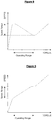
- the braking torque is linearly proportional to the speed only until a threshold 'characteristic speed' is reached. Above this characteristic speed the braking torque response to speed becomes non-linear and peaks before beginning to reduce with further speed increases.
- Figure 1 shows an approximate plot of braking torque against rotation speed for a typical disc-type eddy-current braking system. The characteristic speed is dependant on the resistivity of the disc which is dependant on the temperature, materials, magnetic permeability, and construction of the disc.
- the braking torque of a typical eddy current disc system operating below the characteristic speed is determined approximately by the following relationship: T ⁇ AdB 2 R 2 ⁇
- a non-linear response of braking torque may thus be achieved by varying the magnetic field strength B and/or the distance to the center of rotation R.
- the magnetic field can be supplied by permanent magnets and/or electromagnets.
- the strength of the magnetic field is dependant on the magnetic field intensity and the configuration of the magnetic circuit, i.e. the materials used and spatial positions of the components in the system.
- variation of the magnetic circuit e.g. variation in A, d or R
- Typical eddy-current brake systems thus position the magnets toward the periphery of the disc to maximise R.
- Common magnetic circuit configurations utilise permanent magnets positioned on one or both sides of the disc with steel backing behind each magnet.
- the steel plates are provided to enhance the magnetic field strength while providing structural support for the magnets.
- An auto-belay device is used in climbing, abseiling and the like to control the descent rate of the climber.
- the auto-belay also automatically retracts line when the climber is ascending to maintain line tension thus avoiding slack occurring in the line.
- Friction-brakes clearly have disadvantages compared with eddy-current brakes as the frictional contact involves substantial heat generation, wear and corresponding safety problems. Hydraulic dampening mechanisms are expensive and vulnerable to leaks, pressure and calibration problems.
- An ideal auto-belay system would provide a constant or controllable descent rate with minimal friction and corresponding wear while also providing sufficient braking force in a small compact device.
- Typical prior art plate-type braking systems use various magnetic circuit configurations and have attendant pros and cons. Examples of typical prior art devices are described below.
- One prior art plate-type eddy-current braking device is described in US 4,567,963 by Sugimoto and comprises a conductive disc coupled to a rotor via an overdrive gear arrangement to rotate the disc at a proportionally greater rotational speed than the rotor.
- the rotor includes a spool from which a line is dispensed.
- a series of permanent magnets are attached to an iron plate extending parallel to the disc's plane of rotation and spaced radially with respect to the axis of rotation. These magnets produce eddy-currents in the disc during rotation and, axiomatically, a corresponding magnetic field and braking effect.
- the Sugimoto system also includes radiator fins to assist in dissipation of the heat generated by the eddy-currents in the disc.
- the rotation of the rotor is retarded with an increasing force as the rotational speed ( ⁇ ) increases.
- the overdrive arrangement provides an increased retardant force compared to a disc directly coupled to the rotor and thus, in the Sugimoto device, the aforementioned torque relationship would be similar to T ⁇ AdB 2 R 2 k ⁇ where k is the overdrive gear ratio.
- Sugimoto device may be more effective than simple plate-type systems it cannot be adjusted to vary the braking force applied and relies on an overdrive mechanism to improve braking force i.e. by increasing the relative speed between disc and magnetic field.
- the overdrive mechanism adds to cost, complexity, size, wear, increased heat generation and possibility of failure.
- the Sugimoto device has provided a larger braking effect relative to smaller devices by varying the rotational speed.
- the gear mechanism constrains the limits of size and thus the degree of miniaturisation possible.
- the Sugimoto device is thus undesirable for auto-belays which require a compact device with safe, reliable operation during frequent, and/or prolonged use.
- the Muramatsu device has a rotating disc with a manually adjustable position with respect to a magnet array, thus providing a means in which to vary the area (A) of magnetic field intercepted by the disc.
- the Muramatsu device may be adjustable to vary the braking effect and the maximum braking torque achievable but is still constrained by the size of the disc and strength of magnets, thus proving inconvenient where a smaller size is advantageous, e.g. for auto-belay devices.
- the Muramatsu device must be varied manually.
- the device described by Imanashi et al works on a similar principle to that described by Muramatsu.
- the Imanashi et al system uses a magnet array attached to a linear drive to move the array axially away or toward the disc to respectively reduce or increase the separation and the magnetic field flux the disc intersects.
- the braking effect of the Imanashi et al. cannot be automatically adjusted to accommodate different applied torques.
- a brake for a hoist is described in US 6,460,828 by Gersemsky et al. and uses a magnetic circuit that varies the position of a magnet with respect to a rotating conductive disc.
- the magnet is attached to a free end of a pivoting arm with a spring attached to the free end and to a static point adjacent the disc.
- a reactive force is applied to the magnet by the braking effect to pivot the arm to move the magnet radially outward to increase braking torque.
- the spring will compress and oppose this reactive force thereby providing a braking effect on the disc.
- the Gersemsky et al. system while fulfilling its purpose, is limited in adaptability as the braking torque applied is dependant on only the relative velocity (proportional to speed of rotation and radius to axis of rotation) of the magnets. Furthermore, auto-belay devices typically require braking in only one direction and thus universal braking devices such as the Gersemsky et al. system may be unsuitable.
- DE102005032694 discloses a magnetic brake controller for use with exercise equipment.
- WO9516496 discloses a safety device for automatically belaying a person climbing for sport.
- US4601438 discloses a braking system for a rotating spool casting reel comprising a pair of diametrically opposed weights that are driven outward by centrifugal force, opposed by tension springs.
- WO9734360 discloses a magnetic coupling device has an electroconductive rotor presenting a band of electroconductive material and has a magnet rotor with permanent magnets which are slide-mounted to move radially outward responsive to centrifugal force in opposition to a spring bias.
- an eddy-current braking mechanism according to claim 1.
- the present invention solves the problem of how to effectively smooth varying torque inputs.
- the use of a conductive member in with a pivot point eccentric to the rotation access of the rotor, and a biasing device attached to the conductive member distal to the pivot axis, allows the ability to smooth varying torque inputs.
- movement of the conductive member through the applied magnetic field induces an eddy-current in the conductive member when the conductive member intersects the magnetic field.
- conductive member being coupled to the rotor.
- This 'reverse' configuration may have the magnet coupled to the rotor and configured to move toward a conductive member such that the conductive member will intersect the magnetic field.
- the present invention may also be used in linear braking applications by coupling the rotor to a linear device, e.g. by a cam or chain drive mechanism.
- radial movement of the conductive member should be understood to include any movement with a component in a direction toward or away from the axis of rotation of the rotor and/or conductive member and should be interpreted to include both linear and non-linear radial movement.
- the magnetic field applied by the magnet will herein be referred to as the "applied” magnetic field and the magnetic field(s) generated by eddy-currents in the conductive member are referred to as "reactive" magnetic field(s).
- the eddy-current induced in the conductive member generates a reactive magnetic field opposing the applied magnetic field.
- the reactive force generated by the opposing 'applied' and 'reactive' magnetic fields is thus transferred to the conductive member to oppose movement thereof.
- the rotation of the rotor is also opposed by the reactive force.
- brake or braking respectively refer to any apparatus or process for applying a force opposing movement of an object.
- rotor refers to any rotatable element and may include a: driveshaft, axle, gear, screw, disc, wheel, cog, combination thereof or any other rotatable member.
- conductive member refers to any electrically conductive, preferably non-ferrous member
- magnet refers to any magnet or device capable of generating a magnetic field and may include electromagnets, 'permanent' magnets, 'temporary' magnets, magnetised ferromagnetic materials, or any combination thereof.
- the conductive member is configured to move at least partially radially from the rotor axis into the magnetic field.
- the conductive member rotates with the rotor about the rotor axis.
- the conductive member need not be directly connected to the rotor and could instead be connected via intermediate gears or other couplings.
- the gear or coupling attached to the conductive member can be considered the 'rotor' or part thereof.
- the conductive member may rotate about another axis parallel or non-parallel to the rotor axis.
- the rotor may be coupled to an input shaft or the like via an overdrive, or underdrive, gear transmission arrangement, such that the rotor rotates at a different speed to that of the input shaft.
- the rotor is coupled to a spool of line and configured for rotation therewith.
- the rate of line dispensing, or retracting, from the spool can be controlled by controlling the speed of rotation of the rotor with the braking mechanism.
- the braking mechanism includes a plurality of electrically conductive members (henceforth referred to simply as conductive members).
- the braking effect may be increased by increasing the number of conductive members moving through the applied magnetic field.
- the number and size of the conductive members will be limited by the size and weight constraints of the application.
- preferably three said conductive members are provided.
- the conductive member is pivotally attached to the rotor and configured to pivot about a pivot axis to move at least partially radially into the applied magnetic field upon rotation of the rotor.
- the conductive member is pivotally attached to the rotor at a point eccentric to the rotor axis.
- the conductive member preferably has a center of mass (or mass centroid) eccentric to the pivot and rotor axes.
- the conductive member will thus pivot as a result of torque applied to the conductive member by the rotor via the pivot connection and by centrifugal effects acting on the conductive member which are centred on the center of mass.
- the strength of centrifugal effect is dependant on the rotor speed and applied torque, thus the conductive member will move radially at a rate dependant on the rotor speed as well as a result of applied torque.
- the center of mass may be located at the pivot axis.
- the conductive member may be shaped with a counter balance arrangement with an even mass distribution about the pivot axis.
- Such an example provides a transfer of radial force directly about the pivot axis and as such does not apply a moment to the arm about the pivot axis. Therefore the braked response in this example is independent of the radial force acting on the arm mass.
- the conductive member may be of any shape suitable for the application.
- the shape of the conductive member determines the area of magnetic field intersected by the conductive member when moving radially into the magnetic field, the eddy-currents and reactive magnetic field generated, and therefore the corresponding braking torque.
- the shape of the conductive member may be modified to modify the braking torque characteristics required for an application.
- a biasing device such as a spring or other biasing member/mechanism
- a biasing device is attached to the conductive member at a point distal to the pivot axis and the other end to the rotor at a position to provide a bias opposing the radial movement of the conductive member resulting from rotor rotation.
- Calibration of the biasing device thus provides a means for controlling the rate of radial movement of the conductive member and therefore the area of conductive member intersecting the applied magnetic field.
- the braking force applied to the conductive member during movement through the applied magnetic field may also be applied to the rotor via the biasing device and/or through the attachment of the conductive member to the rotor.
- the biasing device includes a calibration mechanism capable of selectively increasing and/or decreasing the level of biasing device bias applied.
- a calibration mechanism may, for example, be provided by a tensioning screw that is capable of reversibly contracting/extending a spring to thus adjust the biasing device bias applied.
- a tensioning screw may prove useful in calibrating the braking mechanism quickly and easily without requiring disassembling to adjust or replace the biasing device. In auto-belay applications such quick calibration may prove important where it is necessary to change the maximum rotation speed required.
- the biasing device may be configured to bias the conductive member toward or away from the applied magnetic field depending on the requirements of the respective application. For example, in applications requiring increasing braking torque with increasing applied torque (to prevent acceleration), the biasing device biases the conductive member radially out of the applied magnetic field.
- the biasing device may be attached to the conductive member and to the rotor to provide a bias to the conductive member to move the conductive member radially into the applied magnetic field.
- the conductive member may be configured to move radially inward on rotation, e.g. by providing a counterweight or positioning the mass centroid on an opposing side of the pivot axis to the biasing device attachment.
- Such an embodiment may be achieved for example by providing a conductive member on one end of a lever pivotable about an intermediate point, the other lever end having a counterweight configured to move outwardly under centrifugal effects when the rotor rotates.
- the conductive member may be attached to the rotor via a biasing device to bias the conductive member towards the applied magnetic field. Therefore, as the rotor rotates, the lever will pivot the conductive member away from the magnetic field against the bias and braking torque applied to the conductive member.
- the biasing device is attached to the rotor at a position spaced from the eccentric pivot axis in the direction of rotation to be braked.
- the biasing device may be provided as a torsion spring or similar attached at one end to the rotor and at the other end to the conductive member about the pivot axis, the torsion spring configured to oppose pivoting of the conductive member toward or away (depending on the application) from the magnetic field.
- the aforementioned spring configurations constrain the pivoting range of the conductive member between the maximum and minimum spring extension, preferably with, respectively, the maximum and minimum area of conductive member intersecting the applied magnetic field.
- the pivoting range is also preferably constrained to one side of the pivot axis to ensure that the braking torque is only applied in one rotation direction and not the opposing direction.
- Such a 'unidirectional' configuration is useful in auto-belay applications where it is undesirable to have a braking effect on the line when ascending, as this will oppose the line retraction mechanism and potentially create slack in the line.
- the rate at which the conductive member moves toward the magnetic field is dependant on the applied torque, 'spring' bias and the reactionary centrifugal force acting on the conductive member, i.e. the conductive member will move toward the magnetic field if the component of applied torque and centrifugal force (dependant on rotation speed and conductive member mass) opposing the spring bias is greater than the spring bias.
- the eddy-current reactive force will be added to the pivoting caused by the applied torque and centrifugal force, the spring bias thus opposes all three forces and the spring will therefore extend until the restoring force equals the torque applied to the conductive member about the pivot axis.
- the braking mechanism includes a plurality of permanent magnets arranged in a generally circular or arcuate magnet array, concentric with the rotor.
- the braking mechanism may include a plurality of permanent magnets arranged in a linear array, for example in a square or triangular array, with the rotor axis generally in the center thereof.
- two said arrays are provided on opposing sides of the plane of rotation of the conductive member, the magnets of each array having opposite poles substantially opposing each other.
- a magnetic field is thus created that extends between the opposing poles (North opposing South) of opposing magnets, preferably in a direction substantially perpendicular to the plane of rotation of the conductive member.
- one array may be provided on one side of the rotor and a steel or ferromagnetic plate located on the other side.
- a 'one-sided' magnetic array may provide a weaker magnetic field than a comparative two-sided array.
- the magnet array provided on one or both sides of the conductive member may be arranged in a Halbach, or similar configuration to focus the magnetic field in the direction of the conductive member.
- the magnet array is provided with a steel or other ferromagnetic backing attached to a surface of the magnets on an 'outer', opposing side to the conductive member.
- the magnet may be provided as a single magnet shaped to encircle the rotor and conductive member such that radial movement of the conductive member will result in the conductive member intersecting the applied magnetic field.
- the conductive member in order for an eddy-current effect to be generated, the conductive member must intersect and move relative to the magnetic field.
- this may be achieved by:
- the magnet is fixed in position such that it does not rotate with the rotor, the rotor and conductive members rotatable relative to the magnet such that the conductive member intersects and moves through the magnetic field.
- the term “fixed” as used in this embodiment refers to a magnet being static relative to the rotor, e.g. similar to a motor stator.
- the term “fixed” should not be interpreted to mean the magnet is fixed in position relative to any housing, superstructure or other objects.
- the magnet is configured to rotate upon rotation of the rotor at a different angular velocity to that of the rotor.
- Rotation of the magnet(s) relative to the rotor as the rotor is rotating provides a mechanism for varying the relative angular velocity and hence the strength of the braking torque.
- the magnet(s) may be rotated in the same direction as the rotor to reduce the braking torque or in the opposite direction to increase it.
- the magnet is coupled to the rotor for rotation therewith in a substantially opposing direction to that of the rotor.
- the rotor is coupled to the magnet via a coupling transmission.
- a coupling transmission may be used to alter the relative angular velocity of the rotor (and conductive member) relative to the magnet, where the applied torque drives a drum connected to the magnets and coupled to the rotor via a coupling transmission.
- the arrangement may be the other way round.
- a coupling transmission throughout this specification should be understood to refer to a mechanism used to transmit power between two articles to which it is coupled.
- a coupling transmission may be a mechanical or fluid gear transmission, or a chain drive or friction coupling, or by any other such transmission as are well known to those skilled in the art.
- a gear transmission may be configured to rotate the magnet(s) in the opposing direction to that of the rotor, thereby potentially multiplying the relative velocity between the conductive member and magnet.
- This braking mechanism may thus achieve an increased braking effect by increasing the relative speed between the conductive member and magnet, without a significant increase in materials or size.
- the rotor may be coupled to the magnet by a variety of means, including by a chain drive or a friction coupling.
- a stop may be provided for limiting the range of radial movement of the conductive member.
- the stop is positioned to limit the radial movement of the conductive member to a position of maximum magnetic field intercepted.
- Such a stop can be utilised to transfer the braking force applied to the conductive member to the rotor by effectively 'fixing' the conductive member with respect to the rotor while the conductive member is in the magnetic field.
- a stop provides a 'safety' feature to ensure that if the biasing device breaks, detaches or otherwise fails, the conductive member will still apply a braking torque (preferably maximum) to the rotor. Without such a stop, the conductive member may move out of the magnetic field and no longer apply a braking torque.
- the stop may be provided as part of a biased ratchet mechanism, the conductive member moving against the bias to progressive radial positions and thus progressive levels of braking torque.
- an eddy-current braking mechanism including;
- the magnetic field primarily extends substantially orthogonally to the plane of rotation of the conductive member.
- each conductive member capable of reversible movement into a magnetic field applied by one or more of the magnets.
- the conductive member is configured to move with respect to the rotor along a radial track from the rotor axis in response to rotation of the rotor.
- the conductive member is configured to move into the magnetic field as a result of radial acceleration applied by the coupled rotor, the conductive member thus moving radially outward with respect to the rotor.
- a biasing device such as a spring or equivalent biasing member/mechanism is attached to the conductive member and to the rotor to provide a bias opposing the outward radial movement of the conductive member. Calibration of the biasing device thus provides a means for controlling the rate of radial movement of the conductive member and therefore the area of conductive member intersecting the magnetic field.
- This 'linear' example thus provides a braking mechanism that works independent of the direction of rotation of the rotor.
- the configuration of the braking torque applied to both the 'linear' example and 'pivoting' (i.e. with pivoting conductive member) embodiment can be modified and calibrated by changing the level of bias thereby providing an effective means of accommodating applications requiring specific braking torque profiles.
- An eddy-current braking mechanism may be configured such that the speed of rotation of the rotor is constant over a range of applied torques (the "operating range"), the applied torque being the force applied to the rotor causing it to rotate.
- This constant speed of rotation may arise due to any increase in the applied torque (in the operating range) being balanced by an equal and opposite increase in the braking torque arising from the induced eddy current as the conductor intersects more of the magnet field.
- an eddy-current braking mechanism behaves like a prior art device in that the speed of rotation increases substantially linearly with the applied torque. This situation continues until the electrical conductor, which is coupled to the rotor to rotate with it, enters the applied magnetic field of the magnet. Movement of the conductor through the magnetic field induces eddy currents in the conductor which oppose the motion through the magnetic field, thus providing a braking force on the motion of the conductor.
- the magnitude of the braking force depends on a number of factors, including the degree to which the conductor intersects the magnetic field and the strength of the field.
- the strength of the magnetic field, configuration of the conductor, and the biasing mechanism may all be chosen such that an increase in torque applied to the rotor is balanced by an equal and opposite increase in braking torque throughout the required operating range of torque, thus resulting in a constant speed of rotation of the rotor throughout the operating range.
- the conductor may intersecting the maximum area of magnetic field available under the particular embodiment of the invention. At this torque the braking force is also at a maximum. Therefore, as the applied torque is increased further the speed of rotation will again become substantially linear with respect to the increase in applied torque
- a line dispensing device including:
- the line dispensing device is an auto-belay.
- the rotor and/or spool includes a biased retracting mechanism for opposing extension of line from the spool, the retracting mechanism configured to retract the line when tension applied to the line falls below a predetermined level.
- line refers to any cable, rope, string, chain, wire, strap or any other length of flexible material.
- the present invention may be used in any rotary braking and/or speed limiting system.
- Figure 1 shows a plot of Torque vs. Speed for an exemplary prior art eddy-current braking mechanism that utilises a conductive disc configured to rotate in a magnetic field. Eddy-currents are induced in the disc when the disc rotates and a reactive magnetic field is generated opposing the applied magnetic field. The opposing magnetic fields create a reactive force opposing movement of the disc through the magnetic field.
- the magnitude of the braking torque applied to the disc is dependant on the magnetic field strength and the speed of rotation, thus as speed increases, the braking torque also increases.
- This system will limit the speed to a certain level depending on the applied torque.
- the braking torque and therefore equilibrium speed are only linearly proportional to the speed within a predetermined operating range (as shown in figure 1 ), until a threshold characteristic speed' (S) is reached where the braking torque becomes non-linear and peaks before beginning to reduce with further speed increases.
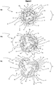
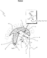
- FIGS 2a-2c , 3 and 5a-5e show an eddy-current braking mechanism according to one preferred embodiment of the present invention as generally indicated by arrow 1. For clarity, in figures 5a-5e only one conductive member 3 is shown attached to the rotor 2.
- the braking mechanism 1 is coupled to a spool of line (not shown) forming part of an auto-belay device (not shown).
- the spool of line is connected to a rotor 2 of the braking mechanism 1 and will thus rotate with the rotor 2.
- a line 23 extends from the spool to a harness of a user.
- the rotor 2 has a biased retracting mechanism (not shown) for opposing the extension of line 23 from the spool and for automatically retracting the line 23 when the line tension (and applied torque) is reduced, e.g. when a user is ascending while climbing.
- the rate of line dispensing from the spool can thus be regulated by controlling the speed of rotation of the rotor 2 with the braking mechanism 1.
- the braking mechanism 1 includes the rotor 2, rotatable about a rotor axis X and three electrically conductive members provided in the form of pivoting arms 3 coupled to the rotor 2.
- the arms 3 are pivotally attached to the rotor 2 at points 8 eccentric to the rotor axis X.
- a plurality of magnets 4 are provided and fixed in position relative to the rotor axis X.
- the magnets 4 form two circular arrays 5 (only one shown in figure 2 ) on opposing sides of the plane of rotation of the arms 3 and rotor 2.
- Figure 3 shows the magnets 4 positioned either side of the plane of rotation of the arms 3.
- Each magnet array 5 is arranged coaxially with the rotor 2 and applies a magnetic field 6 extending orthogonal to the plane of rotation of the arms 3.
- the magnets 4 of the two magnet arrays 5 have opposite poles substantially opposing each other. Thus, a magnetic field 6 is created that extends between the opposing poles (North opposing South) of opposing magnets 4, in a direction orthogonal to the plane of rotation of the rotor 2 and arms 3.
- Steel or other ferromagnetic backing 7 (shown in figure 3 ) is attached to the outer surface of each magnet array 5 on an opposing side to the arms 3. This steel backing 7 helps reinforce the magnetic field 6 as well as potentially protecting the magnets 4 from impact damage.
- the arms 3 have an arc-shaped outer edge 10 matching the profile of the magnet array 5 so that the maximum area of field 6 is intersected while also minimising size and weight of the arms 3.
- the arms 3 are shaped to nest together when the rotor is stationary, i.e. the 'rear' of each conductive member 3 is shaped to abut with the 'front' of the next conductive member 3. It will be appreciated that reference herein to the rotor being "stationary” refers to the rotor not rotating or moving relative to the magnetic field 6.
- each arm 3 pivots about the pivot points 8
- a progressively greater part of each arm 3 moves into and intersects the magnetic field 6.
- the arms 3 are also shaped so that in the contracted position shown in figure 2a , the arms 3 fit together to occupy the minimal amount of space possible, thereby minimising the size requirements of the braking mechanism 1 while maximising the potential braking torque when in the magnetic field 6 as shown in figures 2b and 2c .
- Biasing devices are provided in the form of springs 12 attached to the arms 3 at points 13 distal to the pivot axis 8 and to the rotor 2 at a position 14 spaced from the pivot axis 8 in the direction of rotation R to be braked, i.e. shown as clockwise in figure 2 .
- the springs 12 thereby provide a bias opposing the pivoting (and thereby radial) movement of the arms 3.
- the strength of the springs 12 can be changed to control the movement of the arms 3 toward the magnetic field 6 and therefore the characteristics of the braking mechanism 1.
- the pivoting range of the arms 3 is constrained by the springs 12 to one sector, thereby ensuring that the arms 3 will only move into the magnetic field 6 when rotating in one direction.
- Such a 'unidirectional' configuration is useful in auto-belay applications where it is undesirable to have a braking effect on the line 23 when ascending, as this may oppose the line retraction mechanism and potentially create slack in the line 23.
- Safety stops are attached to the rotor 2 and engage with the arms 3 to limit the range of arms 3 pivoting movement.
- the stops are formed by a sliding engagement between a protrusion (not shown) attached to the arms 3 and a rigid slot (not shown) that is fixed to the rotor 2.
- the protrusion is free to slide in the slot but is limited by the extent of the slot which limits the range of movement of the arms 3.
- the stops (not shown) thus provide a 'safety' feature to ensure that if the spring 12 breaks, detaches or otherwise fails, the arms 3 will still apply a braking torque (preferably maximum) to the rotor 2.
- the stop also assists in transferring braking torque to the rotor 2 when the protrusion reaches the extent of the slot
- the arms 3 are mounted eccentrically to the rotor axis X such that each arm 3 has a center of mass 9 eccentric to the pivot 8 and rotor axes X such that when the rotor 2 rotates, the arms 3 will move radially outward and pivot the arms 3 about the pivot point 8.
- a load e.g. a human
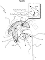
- FIGS. 5a to 5e are partial schematic diagrams showing the forces acting on each arm 3. For clarity, only one arm 3 is shown in figures 5a to 5e .
- each diagram 5a-5e includes a box with the main forces added to show the approximate net force at the center of mass 9. It should be appreciated that these forces are indicative only and the force lines may not be of accurate length or direction.
- Figure 5a shows a force diagram of the eddy-current braking mechanism 1 in an initial 'start-up' stage where there is only a tangentially applied force F App and the spring 12 is not extended.
- F App tangentially to the rotor
- T App is applied to the rotor and it will accelerate from rest.
- Components ( F App (8) and F App (13)) of this force F App are respectively applied to the arm 3 via the pivot point 8 and spring connection 13.
- an arm(s) may be shaped and positioned such that in the start-up phase at least a portion of the arm intersects the magnetic field. An eddy-current braking effect will thus be applied as soon as the rotor starts to rotate.
- the arm 3 also has an inertia resisting changes in movement.
- this inertia will relate to the arm mass and moment of inertia acting about the mass centroid 9.
- Applied Force through pivot 8 F R (8) A resultant force from the combination of F App (8), F App (13), F cp , and F EDDY acting on the rotor via pivot 8 Resultant Force F R A resultant of the force vectors F App (13), F App (8), F cp and F EDDY acting at the arm 3 mass centroid 9.
- Resultant Moment M R A resultant moment acting about the arm 3 mass centroid 9 due to the of the force vectors F App (13), F App (8), F cp and F EDDY and their respective lever arms.
- Braking force caused by eddy-current braking effect F EDDY Braking force caused by eddy-current reactive magnetic field interacting with applied magnetic field 6. Approx proportional to area of magnetic field 6 intersected by the arms 3; strength of the magnetic field 6 intersecting the arms 3; resistivity of the arms 3; and relative velocity of the arms 3 with respect to the magnetic field 6. Braking torque caused by eddy-current braking effect T EDDY Torque applied to the conductive arm 3 by the braking force F EDDY . Approx equal to the F EDDY x / where / is the perpendicular distance from the line of action of the force F EDDY to the pivot point 8, i.e. R 3 in the drawings.
- the arm 3 is constrained at the pivot point 8 but is not rigidly fixed at connection 13.
- Figure 5b shows the applied force F App accelerating the rotor 2 and attached arm 3.
- the arm 3 is pivoted at a greater angular displacement than that shown in figure 5a and now intersects the magnetic field 6.
- the rotor 2 and arm 3 have gained angular velocity about the rotor axis X and the arm 3 is accelerated towards the rotor axis X under centripetal acceleration.
- the mass centroid 9 applies a centrifugal force F cp to the arm 3.
- the eddy-current braking force F EDDY is also applied as the arm 3 is moving through the magnetic field.
- the variables that contribute to the braking torque T B applied to the rotor 2 can all be controlled by appropriate calibration of the springs 12 and mass centroid 9, and thus the braking mechanism 1 can provide substantial control over the braking torque T B response to suit the particular application.
- Figure 5d shows the arm 3 at a point of maximum radial displacement where the maximum magnetic field is intersected by the arm 3.
- the braking torque T B is equal to the applied torque T App .
- any further increases in applied torque T App will not result in the arm 3 moving radially outward as the spring is extended to its maximum extent and the arm 3 is in contact with the safety stop (not shown).
- the braking torque T B can therefore not increase any further. Any further increases in applied torque T App will therefore accelerate the rotor 2.
- Figure 5e shows a decreasing applied torque T App on the braking mechanism 1.
- the arm 3 continues to rotate clockwise about pivot 8 until the forces acting on the arm 3 balance such that the magnitude of F R is zero with a corresponding reduction in the acceleration of the mass centroid 9 to zero and thus the system in in a state of equilibrium.
- the braking torque T B generated by the transfer of the eddy-current braking force F EDDY through the pivot 8 and connection 14 balances the applied torque T App and the acceleration of the rotor 2 is thus zero.
- the speed of rotation can therefore be limited by adjusting the spring bias F S to ensure that the braking torque T B increases proportionally to the applied torque T A and both forces are kept equal throughout an 'operating range' of applied torques.
- the magnitude of the reactive force F EDDY is dependant on the:
- the braking mechanism 1 shown in figures 2-5 provides automatic variation in both the area A of the applied magnetic field 6 intersected and the distance R between the arms 3 and rotor axis X by variation in the radial movement of the arms 3 into the applied magnetic field 6.
- changes in the applied torque T App will result in a commensurate change in the braking torque T B applied to the rotor 2.
- the maximum braking torque achievable will depend on the physical constraints of the mechanism, e.g. size and strength of magnets, size, thickness and conductivity of the arm 3. Furthermore, the rotor 2 must experience a minimum applied torque, and therefore minimum rotational acceleration and speed, before the arm 3 applies a sufficient braking torque to limit the rotation speed.
- the braking mechanism 1 limits the speed in an operating range between these maximum and minimum applied torques. Speed profiles of the braking mechanism 1 showing the operating range are shown in figures 6 and 7 .
- the resultant braking torque T B will increase and then equal the applied torque T App .
- the speed of rotation is thereby limited to a constant value as no acceleration can occur due to the applied torque T App being continually matched by the braking torque T B .
- Increases in applied torque T App are matched by increases in braking torque T B until an upper limit is reached where the maximum area of magnetic field 6 is intersected and thus the magnetic field reactive force F B generated is proportional to speed only. After the upper limit, the speed profile is similar to prior art devices which vary the braking torque T B with speed only.
- the profile shown in figure 8 is achievable by providing a relatively 'weak' spring (i.e. small restoring bias and spring constant) compared with the embodiment shown in figures 6 and 7 such that the braking torque applied upon magnetic field intersection is greater than the applied torque T A throughout the operating range.
- the speed of rotation is reduced with increasing applied torque T App until the applied torque T App exceeds the braking torque T B .
- a relatively 'strong' spring i.e. large restoring bias and spring constant
- the speed of rotation increases linearly with increasing applied torque T App until the braking torque T B exceeds the applied torque T App .
- Figure 10 shows a braking mechanism 100 according to another example to aid understanding of the present invention with the arms provided in the form of plates 103.
- the plates 103 are capable of radial movement along tracks 101 provided in the rotor 102.
- the plates 103 are coupled via the tracks 101 to the rotor 102 so that the plates rotate with the rotor 102 and tracks 101.
- Springs 112 are attached to the rotor 102 and to the plates 103. The springs 112 when extended apply a biasing force F S to bias the plates 103 toward the rotor axis X.
- the torque T App applies a tangential force F App on the plates 103 and the spring applies a centripetal force F cp .
- the centripetal acceleration of the springs 112 toward the rotor axis X results in the plates 103 moving radially outwards into the magnetic field 106 while extending the springs 112.
- the braking force F B applied will vary proportional to the tangential velocity of the plates 103 and the spring bias F S .
- this braking mechanism 100 does not provide a set limit to the speed as the movement of the plates 103 is proportional to the rotor speed, rather than also to the applied torque as in the braking mechanism 1.
- the magnet array (not shown) of this 'linear' example is provided in the same configuration as that shown in the first preferred 'pivoting' embodiment shown in figures 2 and 3 .
- this 'linear' embodiment provides a braking mechanism 100 that works independent of the direction of rotation of the rotor 102.
- the braking mechanism 100 provides a braking effect independent of the rotation direction, the braking torque varies only with the speed of rotation (and therefore centripetal acceleration) and not the torque applied. The speed will only be limited when the braking torque equals the applied torque and thus a greater applied torque (e.g. a heavier person) will result in the speed being limited at a higher equilibrium speed than a correspondingly 'lighter' person. Thus, this braking mechanism 100 does not provide the level of control of the braking mechanism 1 shown in figures 2-5 .
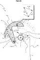
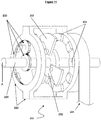
- FIG. 11 Another example of a braking mechanism is generally indicated by arrow 201 in figure 11 .
- an array of magnets (204) is mounted on a cradle (220).
- a rotor (202), having pivotally mounted conductors (203), is mounted on an axle (205) for rotation about the rotor axis (X).
- the cradle (220) is configured to rotate about the rotor axis (X) and is connected to it by a gear transmission (230).
- the gear transmission (230) is configured such that the cradle (220) (including the magnetic array (204)) rotates in an opposite direction to the rotor (202) (and conductors ( 203 )) thus increasing the relative angular velocity of the rotor (202) and conductor members (203) relative to the magnetic array (204).
- Such an arrangement for the braking mechanism may achieve an increased braking effect.
Landscapes
- Engineering & Computer Science (AREA)
- Power Engineering (AREA)
- Health & Medical Sciences (AREA)
- General Health & Medical Sciences (AREA)
- Business, Economics & Management (AREA)
- Emergency Management (AREA)
- Mechanical Engineering (AREA)
- General Engineering & Computer Science (AREA)
- Physical Education & Sports Medicine (AREA)
- Dynamo-Electric Clutches, Dynamo-Electric Brakes (AREA)
Applications Claiming Priority (2)
| Application Number | Priority Date | Filing Date | Title |
|---|---|---|---|
| NZ575464A NZ575464A (en) | 2009-03-10 | 2009-03-10 | Improvements in and relating to braking mechanisms |
| PCT/NZ2010/000011 WO2010104405A2 (en) | 2009-03-10 | 2010-01-29 | Improvements in and relating to braking mechanisms |
Publications (2)
| Publication Number | Publication Date |
|---|---|
| EP2406872A2 EP2406872A2 (en) | 2012-01-18 |
| EP2406872B1 true EP2406872B1 (en) | 2021-02-24 |
Family
ID=42357986
Family Applications (1)
| Application Number | Title | Priority Date | Filing Date |
|---|---|---|---|
| EP10734574.6A Active EP2406872B1 (en) | 2009-03-10 | 2010-01-29 | Improvements in and relating to braking mechanisms |
Country Status (8)
| Country | Link |
|---|---|
| US (8) | US8851235B2 (no) |
| EP (1) | EP2406872B1 (no) |
| JP (2) | JP5767121B2 (no) |
| CN (2) | CN106100285B (no) |
| AU (1) | AU2010221817B2 (no) |
| CA (3) | CA3007550C (no) |
| NZ (1) | NZ575464A (no) |
| WO (1) | WO2010104405A2 (no) |
Families Citing this family (99)
| Publication number | Priority date | Publication date | Assignee | Title |
|---|---|---|---|---|
| NZ575464A (en) * | 2009-03-10 | 2010-07-30 | Holmes Solutions Ltd | Improvements in and relating to braking mechanisms |
| US8052080B2 (en) * | 2009-07-31 | 2011-11-08 | Feng-Chia Liang | Rope breaking device |
| US9272166B2 (en) * | 2010-02-01 | 2016-03-01 | Ride Inc. | Movable cable loop descent system |
| US8659246B2 (en) | 2010-02-23 | 2014-02-25 | Homerun Holdings Corporation | High efficiency roller shade |
| US9249623B2 (en) | 2010-02-23 | 2016-02-02 | Qmotion Incorporated | Low-power architectural covering |
| US8575872B2 (en) | 2010-02-23 | 2013-11-05 | Homerun Holdings Corporation | High efficiency roller shade and method for setting artificial stops |
| US9194179B2 (en) | 2010-02-23 | 2015-11-24 | Qmotion Incorporated | Motorized shade with the transmission wire passing through the support shaft |
| US20110313607A1 (en) * | 2010-06-22 | 2011-12-22 | Checketts Stanley J | Speed control system |
| US8430207B2 (en) * | 2010-06-23 | 2013-04-30 | 3M Innovative Properties Company | Preassembled and pretorqued friction brake and method of making a safety device containing such a friction brake |
| GB201112901D0 (en) * | 2011-07-27 | 2011-09-14 | Renton Julian E | Height rescue apparatus |
| US9744949B2 (en) * | 2011-09-27 | 2017-08-29 | Nabtesco Corporation | Vehicle speed control device and vehicle equipped with vehicle speed control device |
| DE102012210133A1 (de) * | 2012-06-15 | 2013-12-19 | Robert Bosch Gmbh | Werkzeugmaschinenbremsvorrichtung |
| US8739854B2 (en) * | 2012-07-02 | 2014-06-03 | Qmotion Incorporated | Pre-assembled and pre-tensioned shade with indexing gear tensioner |
| US9393475B2 (en) | 2012-09-24 | 2016-07-19 | SportCrafters, Inc. | Progressive resistance system for an exercise device |
| TW201414522A (zh) * | 2012-10-05 | 2014-04-16 | Jui-Lung Chang | 攀降輔助設備 |
| US9334908B2 (en) * | 2012-10-26 | 2016-05-10 | Kudu International Inc. | Centrifugal backspin brake |
| US9623269B2 (en) * | 2013-03-14 | 2017-04-18 | Black Diamond Equipment, Ltd. | Systems for assisted braking belay with a cam-clutch mechanism |
| DE202013012092U1 (de) * | 2013-04-09 | 2015-04-22 | Aerobis Ltd. | Vorrichtung zur Durchführung von Kraftübungen mit Hilfe eines kontinuierlichen, flexiblen Zugmittels |
| GB201314362D0 (en) * | 2013-08-11 | 2013-09-25 | Bowles Robert G | Exercise devise |
| EP2859922B1 (en) * | 2013-10-09 | 2016-05-18 | SportCrafters, Inc. | Progressive resistance system for an exercise device |
| AU2013242869B2 (en) * | 2013-10-10 | 2020-07-23 | Feedback Sports Llc | Progressive resistance device for an exercise device |
| WO2015070089A1 (en) * | 2013-11-08 | 2015-05-14 | RyKo, LLC | Retractable leash |
| CN105745170B (zh) | 2013-11-18 | 2018-07-03 | 奥的斯电梯公司 | 用于乘客输送系统的制动器 |
| NZ619034A (en) | 2013-12-16 | 2015-03-27 | Eddy Current Ltd Partnership | An assembly to control relative speed of movement between parts |
| US9381396B2 (en) | 2014-02-04 | 2016-07-05 | SportCrafters, Inc. | Portable progressive resistance exercise device |
| US10279210B2 (en) * | 2014-05-09 | 2019-05-07 | Albert Ky | Magnetic friction and viscous cylinder-piston resistance portable exercise equipment |
| US9457868B2 (en) * | 2014-08-06 | 2016-10-04 | Shimano Inc. | Bicycle hydraulic quick-release apparatus and bicycle frame |
| AU2015304095B2 (en) | 2014-08-18 | 2020-05-07 | Eddy Current Limited Partnership | Tuning of a kinematic relationship between members |
| KR102305907B1 (ko) * | 2014-08-18 | 2021-09-28 | 에디 커런트 리미티드 파트너쉽 | 래칭 장치 |
| EP3835610A1 (en) * | 2014-08-18 | 2021-06-16 | Eddy Current Limited Partnership | Tuning of a kinematic relationship between members |
| WO2016029060A1 (en) | 2014-08-20 | 2016-02-25 | Mcgowan John Lewis | Eddy current braking device for rotary systems |
| EP3912685A1 (en) * | 2014-12-04 | 2021-11-24 | Eddy Current Limited Partnership | Methods of altering eddy current interactions |
| AU2015355674A1 (en) * | 2014-12-04 | 2017-06-08 | Eddy Current Limited Partnership | Eddy current brake configurations |
| US10693360B2 (en) * | 2014-12-04 | 2020-06-23 | Eddy Current Limited Partnership | Transmissions incorporating eddy current braking |
| KR20220083840A (ko) * | 2014-12-04 | 2022-06-20 | 에디 커런트 리미티드 파트너쉽 | 요소들 사이에서의 래치 활성화 |
| CA2969423C (en) | 2014-12-04 | 2024-01-02 | Eddy Current Limited Partnership | Energy absorbing apparatus |
| GB2535142B (en) * | 2015-01-28 | 2020-07-29 | Latchways Plc | Energy absorber and fall arrest system safety device |
| AU2016252283B2 (en) | 2015-04-20 | 2021-07-01 | John A. BALINT | Apparatus and method for increased realism of training on exercise machines |
| WO2016172509A1 (en) * | 2015-04-24 | 2016-10-27 | Conductix, Inc. | Cable reel eddy current brake |
| DE102015109444B4 (de) * | 2015-06-12 | 2018-08-02 | Bornack Gmbh & Co. Kg | Seilsicherungsvorrichtung |
| US20190118022A1 (en) * | 2015-09-02 | 2019-04-25 | Marcus Carter | Gym cage |
| US10065062B2 (en) | 2015-10-12 | 2018-09-04 | Precor Incorporated | Exercise apparatus with eddy current rail |
| US10668314B2 (en) | 2015-10-16 | 2020-06-02 | Precor Incorporated | Variable distance eddy current braking system |
| CN205163948U (zh) * | 2015-12-02 | 2016-04-20 | 东莞市红火安全科技有限公司 | 一种新型缓降器 |
| BR112018012252B1 (pt) | 2015-12-18 | 2022-08-09 | Eddy Current Limited Partnership | Mecanismo de controle de funcionamento variável para sistema motriz |
| US10022570B2 (en) * | 2016-05-20 | 2018-07-17 | Bailout, LLC | Personal escape device with eddy current braking |
| US9709111B1 (en) * | 2016-05-25 | 2017-07-18 | Warner Electric Technology Llc | Rotational coupling device with non-contact anti-rotation mechanism |
| JP6627179B2 (ja) * | 2016-05-31 | 2020-01-08 | サンヨーホームズ株式会社 | 屋内におけるユーザの動作補助システム |
| US10092788B2 (en) * | 2016-06-07 | 2018-10-09 | Brand 44 Trading Llc | Slackline activity device |
| EP3478372B1 (en) | 2016-06-30 | 2020-04-08 | Newmart Europe B.V. | System for physical mobility activity of a person |
| US10166413B1 (en) | 2016-07-13 | 2019-01-01 | Bailout Systems, Llc | Controlled descent safety systems and methods |
| CN106160402B (zh) * | 2016-07-22 | 2018-09-21 | 山东交通学院 | 一种可自动调节制动力矩的永磁缓速器 |
| KR20190068583A (ko) * | 2016-10-14 | 2019-06-18 | 쓰리엠 이노베이티브 프로퍼티즈 캄파니 | 추락 방지 장치를 사용하여 에너지를 생성하기 위한 방법 및 기구 |
| MX2019003950A (es) | 2016-10-14 | 2019-08-12 | 3M Innovative Properties Co | Generacion y monitoreo de eventos para equipos de proteccion contra caidas. |
| CN106422094A (zh) * | 2016-11-02 | 2017-02-22 | 上海凯悦安全消防器材有限公司 | 阻尼缓降器 |
| GB2556892B (en) * | 2016-11-23 | 2022-04-27 | Latchways Plc | Self-retracting lifeline fall arrest device |
| CN106621088A (zh) * | 2017-01-03 | 2017-05-10 | 武刚 | 高楼逃生设备 |
| CN110446904B (zh) * | 2017-03-24 | 2022-03-08 | 米沃奇电动工具公司 | 具有基于流体的收回速度控制器的卷尺 |
| CN107198837B (zh) * | 2017-06-14 | 2019-09-10 | 台州市洛克赛工具有限公司 | 一种智能逃生背包 |
| WO2019030708A1 (en) * | 2017-08-10 | 2019-02-14 | 3M Innovative Properties Company | GENERATION AND EVENT MONITORING OF ANTI-FALL DEVICE |
| US10828517B2 (en) * | 2017-08-16 | 2020-11-10 | Honeywell International Inc. | Smart fall arrest system |
| US10850847B2 (en) * | 2017-08-31 | 2020-12-01 | Safran Cabin Netherlands N.v. | Slide extractor braking system |
| JP7391014B2 (ja) | 2017-09-20 | 2023-12-04 | メインスプリング エナジー, インコーポレイテッド | 電磁マシンのトランスレータの自動制動 |
| US10333378B2 (en) | 2017-10-06 | 2019-06-25 | Zip-Flyer, Llc | Speed restriction system using eddy currents |
| US10065507B1 (en) * | 2017-10-06 | 2018-09-04 | Zip-Flyer, Llc | Speed restriction systems using eddy currents |
| US11561359B2 (en) * | 2018-02-09 | 2023-01-24 | Carl Zeiss Meditec Ag | Balancing device for rotary apparatus |
| US11844996B2 (en) * | 2018-06-05 | 2023-12-19 | Zipholdings, Llc | Lift, drop, swing, and attenuation apparatus and method |
| US10960252B2 (en) | 2018-06-05 | 2021-03-30 | Zipholdings, Llc | Climbing-wall and pendulum-fall, swing apparatus and method |
| KR20190140298A (ko) * | 2018-06-11 | 2019-12-19 | 주식회사 카펙발레오 | 전기차량용 건식 토크 컨버터 및 그 제어방법 |
| WO2020031064A1 (en) * | 2018-08-07 | 2020-02-13 | 3M Innovative Properties Company | Improvements to fall protection equipment |
| KR20200045800A (ko) * | 2018-10-23 | 2020-05-06 | 주식회사 카펙발레오 | 전기 자동차용 건식 토크 컨버터 및 그 제어방법 |
| KR20200046699A (ko) * | 2018-10-25 | 2020-05-07 | 주식회사 카펙발레오 | 전기 자동차용 건식 토크 컨버터 및 그 제어방법 |
| KR20200050631A (ko) * | 2018-11-02 | 2020-05-12 | 주식회사 카펙발레오 | 전기 자동차용 건식 토크 컨버터 및 그 제어방법 |
| KR20200058021A (ko) * | 2018-11-19 | 2020-05-27 | 주식회사 카펙발레오 | 전기 자동차용 건식 토크 컨버터 및 그 제어방법 |
| KR20200076525A (ko) * | 2018-12-19 | 2020-06-29 | 주식회사 카펙발레오 | 전기 자동차용 건식 토크 컨버터 및 그 제어방법 |
| KR20200078130A (ko) * | 2018-12-21 | 2020-07-01 | 주식회사 카펙발레오 | 전기 자동차용 건식 토크 컨버터 및 그 제어방법 |
| FR3092766B1 (fr) | 2019-02-19 | 2022-06-17 | Abeo | Dispositif d’assurage pour l’escalade à assistance |
| US10923987B2 (en) * | 2019-02-28 | 2021-02-16 | GM Global Technology Operations LLC | Electrical system with cycloidal electric machine |
| KR20200112488A (ko) * | 2019-03-22 | 2020-10-05 | 주식회사 카펙발레오 | 유성기어 잠금장치, 이를 구비한 전기 자동차용 건식 토크 컨버터, 및 그 제어방법 |
| KR20200114813A (ko) * | 2019-03-29 | 2020-10-07 | 주식회사 카펙발레오 | 전기 자동차용 건식 토크 컨버터 및 그 제어방법 |
| RU2729329C1 (ru) * | 2019-09-18 | 2020-08-06 | Сергей Александрович Дорофеев | Электрический ретардер |
| CN114761089B (zh) | 2019-09-20 | 2024-03-15 | 特鲁布鲁有限公司 | 锁止下降控制系统和装置 |
| WO2021092022A1 (en) | 2019-11-05 | 2021-05-14 | TruBlue LLC | Carabiner |
| US11753280B2 (en) * | 2019-11-08 | 2023-09-12 | Goodrich Corporation | Axial rotation damping mechanism |
| RU197275U1 (ru) * | 2019-11-27 | 2020-04-16 | Дмитрий Александрович Дроздов | Устройство для спуска детей с высоты маршрута верёвочного парка при возникновении чрезвычайной ситуации |
| USD945252S1 (en) | 2019-12-18 | 2022-03-08 | TruBlue LLC | Carabiner |
| RU2731825C1 (ru) * | 2020-01-09 | 2020-09-08 | федеральное государственное бюджетное образовательное учреждение высшего образования "Уфимский государственный авиационный технический университет" | Саморегулируемый магнитоэлектрический демпфер с раскрывающимся ротором |
| WO2021188556A1 (en) | 2020-03-18 | 2021-09-23 | TruBlue LLC | Line dispensing devices |
| RU199732U1 (ru) * | 2020-04-03 | 2020-09-16 | федеральное государственное бюджетное образовательное учреждение высшего образования "Уфимский государственный авиационный технический университет" | Саморегулируемый демпфер с многослойным ротором |
| CN111388887A (zh) * | 2020-04-22 | 2020-07-10 | 上海雷德尔实业有限公司 | 磁力缓降确保装置 |
| WO2021246877A1 (en) * | 2020-06-02 | 2021-12-09 | Holmes Solutions Limited Partnership | Movement control system and method of use |
| CN112093566A (zh) * | 2020-10-21 | 2020-12-18 | 诸暨市澳速机械设计工作室 | 一种基于薄膜匀速放卷的缺料预警设备 |
| DE102020130471A1 (de) | 2020-11-18 | 2022-05-19 | Tridelta Magnetsysteme Gmbh | Magnetscheibe, Wirbelstrombremse, Seiltrommel mit Wirbelstrombremse und Verwendung einer derartigen Seiltrommel zur Absicherung eines Industriekletterers |
| US20220161071A1 (en) * | 2020-11-23 | 2022-05-26 | Yoke Industrial Corp. | Fall arrester |
| CN112595879A (zh) * | 2021-01-08 | 2021-04-02 | 上海庸别数码通讯有限公司 | 一种可爬电线杆的电流自动检测装置 |
| EP4313321A1 (en) * | 2021-04-02 | 2024-02-07 | 3M Innovative Properties Company | Cable sleeve for fall protection system |
| WO2022241100A1 (en) * | 2021-05-12 | 2022-11-17 | Frigid Fluid Company | Device and method of monitoring same |
| CN113565582B (zh) * | 2021-07-08 | 2023-06-20 | 中国航发湖南动力机械研究所 | 一种机械式转子超转保护传感器装置 |
| CN115105767B (zh) * | 2022-06-30 | 2023-03-07 | 中冶建工集团有限公司 | 用于攀爬升降的辅助机构 |
Citations (2)
| Publication number | Priority date | Publication date | Assignee | Title |
|---|---|---|---|---|
| US4601438A (en) * | 1985-04-29 | 1986-07-22 | Charles C. Worth Corporation | Bait casting reel with braking device |
| WO1997034360A1 (en) * | 1996-03-15 | 1997-09-18 | Magna Force, Inc. | Magnetic centrifugal clutch |
Family Cites Families (191)
| Publication number | Priority date | Publication date | Assignee | Title |
|---|---|---|---|---|
| US2058024A (en) | 1934-12-11 | 1936-10-20 | Westinghouse Air Brake Co | Eddy current brake |
| US2112312A (en) | 1935-09-05 | 1938-03-29 | Moore Drop Forging Company | One-piece shrouded hinge member and method of forming same |
| US2122315A (en) * | 1936-06-11 | 1938-06-28 | Fosty Leopold | Fire escape |
| US2122312A (en) | 1937-05-25 | 1938-06-28 | Cassion John | Door attachment |
| FR925341A (no) | 1944-06-14 | 1947-09-16 | ||
| US2409009A (en) | 1945-07-24 | 1946-10-08 | Gen Electric | One-way drive with magnetic lock |
| US2492776A (en) | 1948-08-11 | 1949-12-27 | Martin P Winther | Dynamoelectric machine |
| GB721748A (en) | 1950-06-22 | 1955-01-12 | Baermann Max | Improvements in or relating to permanent magnet brakes or clutches |
| US2771171A (en) | 1955-07-06 | 1956-11-20 | Lab Equipment Corp | Magnetically activated torque coupling |
| GB908128A (en) | 1958-06-10 | 1962-10-17 | Andre Duban | Improvements in or relating to ratchet-and-pawl devices |
| FR1418814A (fr) | 1964-03-27 | 1965-11-26 | Renault | Perfectionnements aux dispositifs à courants de foucault pour la commande automatique des changements de rapports de vitesses sur véhicules |
| US3447006A (en) * | 1967-09-28 | 1969-05-27 | Bliss Co | Electrodynamic brake of magnetic fluid type |
| DE2032935A1 (de) | 1970-07-03 | 1972-01-13 | Kabel Metallwerke Ghh | Vorrichtung zur Konstanthaltung von Geschwindigkeit und Zugkraft eines von einer Spule ablaufenden Drahtes |
| JPS48109391U (no) * | 1972-03-27 | 1973-12-17 | ||
| DE2402748C2 (de) | 1974-01-21 | 1986-07-03 | Artur 7060 Schorndorf Föhl | Vorrichtung zur Einleitung der Spulenwellenblockierung eines Sicherheitsgurt- Aufrollautomaten |
| US3962595A (en) | 1974-12-20 | 1976-06-08 | W. J. Industries, Incorporated | Magnetic particle brake |
| US4036428A (en) | 1976-04-29 | 1977-07-19 | Beckman Instruments, Inc. | Fluid pressure operated eddy current brake for air driven centrifuge |
| US4093186A (en) * | 1976-11-22 | 1978-06-06 | Golden Steven T | Line brake device useful for fire escape |
| GB1599300A (en) | 1977-08-27 | 1981-09-30 | Ferranti Ltd | Speed control |
| US4271944A (en) | 1979-02-12 | 1981-06-09 | Hanson Douglas R | Single revolution torque limiting clutch |
| US4306688A (en) * | 1979-02-22 | 1981-12-22 | Injecto Mold, Inc. | Hose reel assembly |
| US4434971A (en) * | 1981-02-11 | 1984-03-06 | Armco Inc. | Drilling rig drawworks hook load overspeed preventing system |
| US4561605A (en) * | 1981-12-25 | 1985-12-31 | Shimano Industrial Company Limited | Brake for a fishing reel |
| US4416430A (en) * | 1982-02-01 | 1983-11-22 | Draft Systems, Inc. | Load lowering device |
| US4544111A (en) | 1982-03-09 | 1985-10-01 | Shimano Industrial Company Limited | Brake for a fishing reel |
| JPS59217589A (ja) * | 1983-05-26 | 1984-12-07 | 株式会社宮野鉄工所 | 緩降機 |
| US4612469A (en) | 1983-11-10 | 1986-09-16 | Kabushiki Kaisha Sankyo Seiki Seisakusho | Speed governor |
| JPS6115557A (ja) | 1984-06-30 | 1986-01-23 | Toshiba Corp | 浮上式搬送装置 |
| JPS60226763A (ja) * | 1984-11-26 | 1985-11-12 | Yasuda Seisakusho:Kk | 電磁式制動装置 |
| JPS62171458A (ja) * | 1986-01-24 | 1987-07-28 | Kohei Minato | 磁力回転装置 |
| US4957644A (en) | 1986-05-13 | 1990-09-18 | Price John T | Magnetically controllable couplings containing ferrofluids |
| DE3864969D1 (de) | 1987-04-30 | 1991-10-24 | Tokyo Buhin Kogyo Co Ltd | Foucaultstrombremse. |
| CA1315328C (en) * | 1988-10-31 | 1993-03-30 | Kenji Araki | Eddy current retarder |
| US4938435A (en) * | 1988-12-30 | 1990-07-03 | Frost Engineering Development Corporation | Personnel lowering device |
| KR910021550A (ko) | 1990-02-02 | 1991-12-20 | 발터 쾰러 | 와이어 브레이크 |
| DE4018214A1 (de) | 1990-06-07 | 1991-12-12 | Harting Elektronik Gmbh | Vorrichtung zur elektromagnetischen betaetigung eines sperrmechanismus eines gurtaufrollers |
| GB9027783D0 (en) * | 1990-12-21 | 1991-02-13 | Barrow Hepburn Sala Ltd | Safety anchorages for controlling pay-out of a safety line |
| US5205386A (en) | 1992-03-05 | 1993-04-27 | United Technologies Corporation | Pawl and ratchet clutch with pawl holdback |
| JP3584473B2 (ja) | 1992-04-22 | 2004-11-04 | Fdk株式会社 | 磁気ダンパ装置 |
| DE9300966U1 (no) * | 1993-01-25 | 1993-03-11 | Chen, Jeff, Shyong City, Tw | |
| US5712520A (en) | 1993-05-21 | 1998-01-27 | Magna Force, Inc. | Permanent magnet braking system |
| US5636804A (en) | 1993-10-05 | 1997-06-10 | Bando Leports, Ltd. | Double-bearing fishing reel |
| WO1995016496A1 (en) * | 1993-12-14 | 1995-06-22 | Strickler James H | Sport climbing safety device |
| US5465815A (en) * | 1994-01-10 | 1995-11-14 | Ikegami; Iwao | Magnetic brake |
| EP0739225B1 (en) | 1994-01-13 | 1997-12-29 | Barrow Hepburn Sala Limited | Speed responsive coupling device especially for fall arrest apparatus |
| EP0740570B1 (en) * | 1994-01-18 | 1997-12-03 | Barrow Hepburn Sala Limited | Clutch mechanism for use in safety apparatus |
| JP2929517B2 (ja) * | 1994-04-01 | 1999-08-03 | ダイワ精工株式会社 | 魚釣用リールのバックラッシュ防止装置 |
| US5441137A (en) | 1994-05-04 | 1995-08-15 | Eaton Corporation | Clutch with a centrifugally applied ball ramp actuator |
| US5862891A (en) | 1994-10-28 | 1999-01-26 | Knorr-Bremse Systeme Fur Scheinenfahrzeuge Gmbh | Electromagnetic or permanent-magnetic rail brake |
| US5862903A (en) | 1994-12-02 | 1999-01-26 | Itt Automotive Electrical Systems, Inc. | Centrifugal clutch for power door locks |
| JP3360281B2 (ja) | 1995-03-15 | 2002-12-24 | 株式会社アテックス | ベール径可変型ロールベーラ |
| DE29506374U1 (de) | 1995-04-13 | 1996-10-02 | Funex Ag | Belustigungsvorrichtung |
| US5791584A (en) | 1996-01-25 | 1998-08-11 | Kuroiwa; Sachimasa | Tension control unit for filamentous material |
| US5822874A (en) | 1996-04-29 | 1998-10-20 | Nemes; Anne | Automatically retracting chalk line marking tool |
| DE19618903C2 (de) | 1996-05-10 | 1998-03-19 | Knorr Bremse Systeme | Magnetische Bremse, insbesondere lineare Wirbelstrombremse |
| US20040194101A1 (en) | 1997-08-21 | 2004-09-30 | Glanzer David A. | Flexible function blocks |
| JPH1098868A (ja) * | 1996-09-24 | 1998-04-14 | Aichi Steel Works Ltd | 電磁ブレーキの磁極配列方式 |
| US5779178A (en) | 1996-11-07 | 1998-07-14 | Rostra Precision Controls, Inc. | Seat belt retractor assembly having magnetically actuated locking mechanism |
| JPH10140536A (ja) | 1996-11-12 | 1998-05-26 | Taisei Corp | 水中マット布設用架台と水中マット布設方法 |
| US5711404A (en) * | 1997-02-05 | 1998-01-27 | Lee; Ying-Che | Magnetic adjustable loading device with eddy current |
| US5742986A (en) | 1997-02-13 | 1998-04-28 | Trw Inc. | Seat belt buckle with hall effect locking indicator and method of use |
| US6086005A (en) * | 1997-03-11 | 2000-07-11 | Daiwa Seiko, Inc. | Fishing reel with magnetic force spool rotational-speed control during spool free rotational state |
| JPH10252025A (ja) | 1997-03-12 | 1998-09-22 | N D K:Kk | 自発光式道路鋲 |
| AU7358998A (en) | 1997-04-14 | 1998-11-11 | David A Zornes | Magnet coupler having enhanced electromagnetic torque |
| JP3835014B2 (ja) | 1997-10-20 | 2006-10-18 | 東亞合成株式会社 | 硬化性組成物 |
| JPH11119680A (ja) | 1997-10-20 | 1999-04-30 | Ricoh Co Ltd | 液晶表示装置 |
| US5928300A (en) | 1997-10-30 | 1999-07-27 | Simula Inc. | Three-axis aircraft crash sensing system |
| JP3961668B2 (ja) * | 1998-05-06 | 2007-08-22 | 美和ロック株式会社 | 引戸のクローザ |
| US6042517A (en) | 1998-09-10 | 2000-03-28 | Bell Sports, Inc. | Bicycle trainer magnetic resistance device |
| DE19859445C2 (de) * | 1998-12-22 | 2001-01-11 | Asm Automation Sensorik Messte | Meßseil-Wegsensor mit einem Längsantrieb für die Seiltrommel |
| DE19951221A1 (de) | 1999-04-01 | 2000-10-05 | Mannesmann Ag | Windwerk, insbesondere Hebezeug, mit einem Gehäuse |
| JP2000316272A (ja) * | 1999-04-27 | 2000-11-14 | Topre Corp | 自転車の最高速度制限装置 |
| DE19919122A1 (de) * | 1999-04-27 | 2000-11-02 | Iro Patent Ag Baar | Aktuator und Fadenbremse mit einem Aktuator |
| US6051897A (en) | 1999-05-05 | 2000-04-18 | Synchro-Start Products, Inc. | Solenoid actuator with positional feedback |
| JP2001017041A (ja) * | 1999-07-02 | 2001-01-23 | Akebono Brake Ind Co Ltd | 両軸リール用ブレーキ機構 |
| DE29912725U1 (de) * | 1999-07-21 | 1999-10-07 | Chen Yu Peng | Magnetische Dämpfungseinrichtung für ein Übungsgerät |
| GB2352645B (en) | 1999-07-21 | 2004-01-14 | Yu-Peng Chen | Magnetic damping device for an exercising device |
| GB2352784A (en) | 1999-08-04 | 2001-02-07 | Moog Inc | Energy-absorbing brake |
| US6360855B1 (en) * | 1999-11-15 | 2002-03-26 | Cheng Szu-Yin | Wheel for a stationary bicycle |
| US6293376B1 (en) | 1999-11-22 | 2001-09-25 | Magnetar Technologies Ltd | Apparatus including eddy current braking system |
| US20040055836A1 (en) | 1999-11-22 | 2004-03-25 | Pribonic Edward M. | Eddy current braking apparatus with adjustable braking force |
| US20060278478A1 (en) | 1999-11-22 | 2006-12-14 | Pribonic Edward M | Eddy current braking apparatus with adjustable braking force |
| GB2357563B (en) | 1999-12-21 | 2002-04-03 | Latchways Plc | Energy absorber |
| US6533083B1 (en) | 2000-02-15 | 2003-03-18 | Magnetar Technologies, Inc | Eddy current braking apparatus |
| AU2001241473A1 (en) | 2000-02-15 | 2001-08-27 | Magnetar Technologies Ltd. | Eddy current braking apparatus |
| DE20003513U1 (de) * | 2000-02-28 | 2001-07-26 | Wirth Co Kg Masch Bohr | Hebewerk |
| AU2001273177A1 (en) | 2000-07-06 | 2002-01-21 | Rose Manufacturing Company | Controlled descent device |
| US6412611B1 (en) | 2000-07-17 | 2002-07-02 | Magnetar Technologies, Ltd | Eddy current brake system with dual use conductor fin |
| EP1193724B1 (en) | 2000-09-18 | 2010-02-17 | Isuzu Motors Limited | Eddy current retarder comprising a magnet consisting of an electromagnet and a permanent magnet |
| WO2002027206A1 (fr) | 2000-09-29 | 2002-04-04 | Feng Jin | Roue libre |
| US20020162477A1 (en) | 2001-03-02 | 2002-11-07 | Emiliano Palumbo | Dual cable zipline having mechanical ascension and braking systems |
| US7014026B2 (en) | 2001-06-07 | 2006-03-21 | Drussel Wilfley Design, L.L.C. | Manual/automatic pressure control mechanism for centrifugal clutch |
| DE10149112B4 (de) | 2001-10-05 | 2004-11-25 | Robert Bosch Gmbh | Verfahren zur Bestimmung einer Auslöseentscheidung für Rückhaltemittel in einem Fahrzeug |
| US6585087B2 (en) * | 2001-10-12 | 2003-07-01 | Yuan Ho Chuen Co., Ltd. | Control mechanism for use in magnetically operated wheels |
| US6698554B2 (en) | 2001-12-21 | 2004-03-02 | Visteon Global Technologies, Inc. | Eddy current brake system |
| US6557673B1 (en) * | 2001-12-21 | 2003-05-06 | Visteon Global Technologies, Inc. | Integral park brake/eddy current brake assembly |
| WO2003055560A1 (de) | 2001-12-28 | 2003-07-10 | Suter Racing International Ag | Abseilvorrichtung als rettungsgerät für katastrophenfälle, insbesondere brandfälle bei gebäuden oder hochhäusern |
| US7011607B2 (en) * | 2002-01-23 | 2006-03-14 | Saris Cycling Group, Inc. | Variable magnetic resistance unit for an exercise device |
| WO2003073592A1 (fr) | 2002-02-28 | 2003-09-04 | Sumitomo Metal Industries, Ltd. | Reducteur de vitesse a courants de foucault |
| US6723017B2 (en) | 2002-05-09 | 2004-04-20 | Visteon Global Technologies, Inc. | Differential assembly |
| EP2306621A1 (en) | 2002-09-20 | 2011-04-06 | Tai-Her Yang | Axially movable rotor |
| EP1432101B1 (en) | 2002-12-20 | 2019-03-20 | Tai-Her Yang | Electrical machine with structure for axially moving the rotor using centrifugal force |
| TWI298621B (en) * | 2003-01-06 | 2008-07-11 | Shimano Kk | Braking device for a dual bearing reel |
| GB2398054B (en) * | 2003-01-24 | 2005-08-03 | Ropepower Ltd | Powered rope climbing apparatus |
| WO2004073928A2 (en) | 2003-02-19 | 2004-09-02 | Archer Daniels Midland Company | Methods and composition for dust and erosion control |
| KR20050118271A (ko) * | 2003-02-21 | 2005-12-16 | 라이프-팩 테크놀러지스, 인코포레이티드 | 빌딩 탈출 장치 |
| JP4067995B2 (ja) | 2003-03-28 | 2008-03-26 | ヒタチグローバルストレージテクノロジーズネザーランドビーブイ | 回転円板型記憶装置並びにアクチュエータ・サスペンション・アセンブリの解放方法 |
| TWM251925U (en) | 2003-08-21 | 2004-12-01 | Jung-Rung Shie | Brake structure for rolling door |
| US7281620B2 (en) * | 2003-09-05 | 2007-10-16 | D B Industries, Inc. | Self-retracting lifeline |
| US7706777B2 (en) | 2003-09-23 | 2010-04-27 | Broadcom Corporation | Secure user interface in a shared resource environment |
| DE102004007434A1 (de) | 2004-02-16 | 2005-09-22 | Minebea Co., Ltd. | Elektrische Maschine |
| US7294947B2 (en) | 2004-03-01 | 2007-11-13 | Flux Drive, Inc. | Apparatus for transferring torque magnetically |
| WO2005090037A1 (en) | 2004-03-12 | 2005-09-29 | Intellipack | Hand held dispenser |
| DE102004013836A1 (de) | 2004-03-16 | 2005-10-06 | Bielomatik Leuze Gmbh + Co.Kg | Verfahren zum Rotationsreibschweißen von Kunststoffteilen sowie Vorrichtung zur Durchführung des Verfahrens |
| DE602005002743T2 (de) * | 2004-04-29 | 2008-01-24 | Terex-Demag Gmbh & Co. Kg | Seilwickelsystem zum Auf- und Abwickeln von Stahlseilen von Kranen |
| US8727078B2 (en) | 2004-05-28 | 2014-05-20 | Velocity Magnetics, Inc. | Selectively incrementally actuated linear eddy current braking system |
| GB2415818B (en) | 2004-06-30 | 2008-12-31 | Autoliv Dev | Arrangement for triggering a vehicle safety device |
| US20100211239A1 (en) * | 2004-08-06 | 2010-08-19 | Christensen Ladd E | Towrope Winch Dead Start |
| CN1783674A (zh) | 2004-11-24 | 2006-06-07 | 乐金电子(天津)电器有限公司 | 圆筒型涡电流轴连接装置 |
| US7018324B1 (en) * | 2004-11-30 | 2006-03-28 | Lily Lin | Magnetic controlled loading device in combination of a power generating set and an adjusting drive mechanism |
| DE102005036570A1 (de) * | 2004-12-16 | 2006-07-06 | Steinert Elektromagnetbau Gmbh | Verfahren zur Abbremsung eines laufenden Metallbandes und Anlage zur Durchführung des Verfahrens |
| JP5296287B2 (ja) | 2005-03-15 | 2013-09-25 | 富士電機株式会社 | 半導体装置 |
| GB0507806D0 (en) * | 2005-04-19 | 2005-05-25 | Bm Engineering Uk Ltd | Belay device |
| US8079569B2 (en) | 2005-04-29 | 2011-12-20 | Gerald Lesko | Cable drawworks for a drilling rig |
| US20070001048A1 (en) * | 2005-05-18 | 2007-01-04 | Wooster Peter C | Descent device |
| WO2007005560A2 (en) | 2005-06-30 | 2007-01-11 | Magnetar Technologies Corp. | Axial rotary eddy current brake with adjustable braking force |
| DE102005032694A1 (de) * | 2005-07-13 | 2007-01-18 | Forhouse Corp., Shenkang | Lastregler einer Magnetbremse für ein Übungsgerät |
| GB2432140A (en) * | 2005-11-15 | 2007-05-16 | Latchways Plc | Fall arrest safety device |
| US20070135561A1 (en) | 2005-12-08 | 2007-06-14 | Christian Rath | Method of dust abatement |
| JP2007276540A (ja) | 2006-04-03 | 2007-10-25 | Honda Motor Co Ltd | 車両の乗員拘束装置 |
| US7528514B2 (en) * | 2006-06-22 | 2009-05-05 | International Business Machines Corporation | Centrifugal magnetic clutch |
| WO2008008225A2 (en) * | 2006-07-10 | 2008-01-17 | Sigma Industries, Llc | Retractable lifeline safety device |
| US20080074223A1 (en) | 2006-09-22 | 2008-03-27 | Pribonic Edward M | Reinforcing of permanent magnet arrays |
| US7984796B2 (en) | 2006-10-13 | 2011-07-26 | Magnetar Technologies Corp. | Motion retarding system and method |
| US7843349B2 (en) * | 2006-11-03 | 2010-11-30 | D B Industries, Inc. | Retrofittable radio frequency identification connector |
| US20080105503A1 (en) | 2006-11-08 | 2008-05-08 | Pribonic Edward M | Axial rotary eddy current brake with self-adjustable braking force |
| GB2451799B (en) | 2007-05-16 | 2011-12-14 | Latchways Plc | Safety device |
| TW200920438A (en) * | 2007-07-18 | 2009-05-16 | Stone S Throw Llc | Personal escape device and methods for using same |
| GB2449134B (en) * | 2007-08-13 | 2009-08-12 | Checkmate Safety Llp | Fall arrest block |
| US8893854B2 (en) * | 2007-09-28 | 2014-11-25 | D B Industries, Llc | Retractable lifeline assembly |
| AU2007359899B2 (en) | 2007-10-12 | 2013-09-05 | Latchways Plc | Rotational energy absorber and fall arrest system |
| US9016432B2 (en) * | 2007-12-10 | 2015-04-28 | Rapid Egress Descent Systems Ltd. | Descent control device |
| US8272476B2 (en) * | 2007-12-10 | 2012-09-25 | Rapid Egress Descent Systems Ltd. | Descent control device |
| US7918323B2 (en) * | 2007-12-16 | 2011-04-05 | Sports Art Industrial Co., Ltd | Magnetic resistor control assembly |
| JP5122273B2 (ja) * | 2007-12-28 | 2013-01-16 | 株式会社シマノ | 両軸受リールのスプール制動装置 |
| US8561759B2 (en) | 2008-02-27 | 2013-10-22 | Rapid Vertical Egress System Holding B.V. | Rescue arrangement |
| CN101559267A (zh) | 2008-04-18 | 2009-10-21 | 陈锦鹏 | 一种防坠落设备及系统 |
| US10001804B2 (en) | 2008-08-11 | 2018-06-19 | Force Dimension S.A.R.L. | Force-feedback device and method |
| US20100112224A1 (en) | 2008-10-30 | 2010-05-06 | James A Lott | Methods and formulations for protection ans dust control involving bulk material |
| US20100116922A1 (en) * | 2008-11-13 | 2010-05-13 | Reliance Industries, Llc | Cable reel lock for fall arrestor |
| US9764172B2 (en) * | 2009-03-09 | 2017-09-19 | D B Industries, Llc | Safety device with fall arrest and descending modes |
| US10688323B2 (en) * | 2009-03-09 | 2020-06-23 | D B Industries, Llc | Safety device with fall arrest and descending modes |
| NZ575464A (en) * | 2009-03-10 | 2010-07-30 | Holmes Solutions Ltd | Improvements in and relating to braking mechanisms |
| KR100969227B1 (ko) * | 2009-09-28 | 2010-07-14 | 주식회사 코커스 | 낚시용 릴의 브레이크 시스템 |
| WO2011042985A1 (ja) | 2009-10-09 | 2011-04-14 | トヨタ自動車株式会社 | 回転電機装置 |
| US8226024B2 (en) * | 2009-10-14 | 2012-07-24 | D B Industries, Inc. | Self-retracting lifeline with reserve lifeline portion |
| US8556234B2 (en) * | 2009-11-13 | 2013-10-15 | Ride Inc. | Single cable descent control device |
| AU2010336378B2 (en) | 2009-12-23 | 2013-10-10 | D B Industries, Llc | Fall protection safety device with a braking mechanism |
| US20110174914A1 (en) * | 2010-01-20 | 2011-07-21 | Gimmal Co., Ltd. | Connector device to prevent person from falling |
| GB201002854D0 (en) | 2010-02-19 | 2010-04-07 | Wavefront Reservoir Technologies Ltd | Magnet - operated pulsing tool |
| US20110240403A1 (en) * | 2010-03-31 | 2011-10-06 | D B Industries, Inc. | Lifeline Connector for Use with Self-Retracting Lifeline with Disconnectable Lifeline |
| EP2377783A1 (de) * | 2010-04-14 | 2011-10-19 | Interroll Holding AG | Förderrolle mit Fliehkraftbetätigter Magnetbremse. |
| US9199103B2 (en) * | 2010-05-12 | 2015-12-01 | Msa Technology, Llc | Fall protection arrangement |
| US8469149B2 (en) * | 2010-06-07 | 2013-06-25 | D B Industries, Llc | Self-retracting lifeline with disconnectable lifeline |
| WO2012068420A2 (en) * | 2010-11-17 | 2012-05-24 | Reliance Industries, Llc | Retractable fall arrester with component assembly and cantilevered main shaft |
| US8424460B2 (en) | 2010-12-28 | 2013-04-23 | Shawn Geoffrey LERNER | Trolley for downhill zip line thrill ride |
| EP2487547B1 (fr) * | 2011-02-11 | 2017-08-09 | Montres Breguet SA | Régulateur de mobile horloger ou de mobile de sonnerie |
| WO2013003402A2 (en) * | 2011-06-29 | 2013-01-03 | Key Safety Systems, Inc. | Fall arrester |
| CN202203305U (zh) | 2011-08-01 | 2012-04-25 | 台州市黄岩华阳机电科技有限公司 | 离心式离合器和具有该离合器的电动车变挡驱动轮毂 |
| US9744949B2 (en) | 2011-09-27 | 2017-08-29 | Nabtesco Corporation | Vehicle speed control device and vehicle equipped with vehicle speed control device |
| US9033115B2 (en) | 2011-11-11 | 2015-05-19 | Shawn Lerner | Zip line braking |
| US8601951B2 (en) | 2011-11-11 | 2013-12-10 | Shawn Lerner | Self-cooling trolley |
| CN102497085A (zh) | 2011-12-23 | 2012-06-13 | 浙江大学 | 一种基于Halbach阵列的永磁涡流缓速器 |
| US8857578B2 (en) * | 2012-01-19 | 2014-10-14 | Technical Film Systems, Inc. | Magnetic brake |
| DE102012202553A1 (de) | 2012-02-20 | 2013-08-22 | Carl Zeiss Smt Gmbh | Lithographievorrichtung mit dämpfungsvorrichtung |
| CN102627063B (zh) | 2012-03-05 | 2014-05-28 | 江苏大学 | 电磁馈能型半主动悬架运动方向实时控制装置及方法 |
| US20140110947A1 (en) | 2012-10-24 | 2014-04-24 | Vestas Wind Systems A/S | Wind turbine generator having an eddy current brake, wind turbine having such a generator, and associated methods |
| CN103127627B (zh) * | 2013-01-30 | 2015-07-08 | 黄柏源 | 一种双制动往返可控式缓降器 |
| CN103244577A (zh) | 2013-04-27 | 2013-08-14 | 上海法诺格绿色能源系统有限公司 | 超越离合器 |
| CN103326538B (zh) | 2013-06-25 | 2016-01-20 | 常州市博能节能科技有限公司 | 永磁智能调速节能装置 |
| NZ619034A (en) | 2013-12-16 | 2015-03-27 | Eddy Current Ltd Partnership | An assembly to control relative speed of movement between parts |
| US10046745B2 (en) | 2014-03-20 | 2018-08-14 | TruBlue LLC | Cable-traversing trolley adapted for use with impact braking |
| TWM492758U (zh) * | 2014-07-24 | 2015-01-01 | Chiu-Hsiang Lo | 運動器之磁控阻力調整機構 |
| AU2015304095B2 (en) | 2014-08-18 | 2020-05-07 | Eddy Current Limited Partnership | Tuning of a kinematic relationship between members |
| EP3835610A1 (en) | 2014-08-18 | 2021-06-16 | Eddy Current Limited Partnership | Tuning of a kinematic relationship between members |
| KR102305907B1 (ko) | 2014-08-18 | 2021-09-28 | 에디 커런트 리미티드 파트너쉽 | 래칭 장치 |
| KR20220083840A (ko) | 2014-12-04 | 2022-06-20 | 에디 커런트 리미티드 파트너쉽 | 요소들 사이에서의 래치 활성화 |
| US10022570B2 (en) * | 2016-05-20 | 2018-07-17 | Bailout, LLC | Personal escape device with eddy current braking |
| US9723823B2 (en) | 2016-08-29 | 2017-08-08 | Terry Richardson | Fishing line dispenser |
| US10333378B2 (en) * | 2017-10-06 | 2019-06-25 | Zip-Flyer, Llc | Speed restriction system using eddy currents |
| US20190144244A1 (en) * | 2017-11-14 | 2019-05-16 | TruBlue LLC | Cable and structure traversing trolleys |
-
2009
- 2009-03-10 NZ NZ575464A patent/NZ575464A/en unknown
-
2010
- 2010-01-29 CA CA3007550A patent/CA3007550C/en active Active
- 2010-01-29 CA CA2789535A patent/CA2789535C/en active Active
- 2010-01-29 CN CN201610176676.5A patent/CN106100285B/zh active Active
- 2010-01-29 US US13/255,625 patent/US8851235B2/en active Active
- 2010-01-29 JP JP2011553971A patent/JP5767121B2/ja active Active
- 2010-01-29 WO PCT/NZ2010/000011 patent/WO2010104405A2/en active Application Filing
- 2010-01-29 AU AU2010221817A patent/AU2010221817B2/en active Active
- 2010-01-29 EP EP10734574.6A patent/EP2406872B1/en active Active
- 2010-01-29 CA CA3105810A patent/CA3105810C/en active Active
- 2010-01-29 CN CN201080020158.5A patent/CN102428633B/zh active Active
- 2010-08-18 US US12/858,839 patent/US8490751B2/en active Active
-
2013
- 2013-06-21 US US13/924,004 patent/US9016435B2/en active Active
-
2014
- 2014-08-20 US US14/464,255 patent/US10518115B2/en active Active
-
2015
- 2015-02-06 JP JP2015022428A patent/JP6053838B2/ja active Active
- 2015-03-03 US US14/637,153 patent/US9962588B2/en active Active
-
2017
- 2017-05-03 US US15/586,111 patent/US10065054B2/en active Active
-
2018
- 2018-03-29 US US15/939,969 patent/US11123580B2/en active Active
-
2019
- 2019-11-21 US US16/691,509 patent/US20200155874A1/en active Pending
Patent Citations (2)
| Publication number | Priority date | Publication date | Assignee | Title |
|---|---|---|---|---|
| US4601438A (en) * | 1985-04-29 | 1986-07-22 | Charles C. Worth Corporation | Bait casting reel with braking device |
| WO1997034360A1 (en) * | 1996-03-15 | 1997-09-18 | Magna Force, Inc. | Magnetic centrifugal clutch |
Also Published As
Similar Documents
| Publication | Publication Date | Title |
|---|---|---|
| US10065054B2 (en) | Braking mechanisms | |
| JP7426097B2 (ja) | 渦電流ブレーキ装置、オートビレイ装置およびセルフリトラクティングライフライン装置 | |
| WO2020071986A1 (en) | Flywheel exercise method, apparatus and the use therefor | |
| NZ770592A (en) | Eddy current brake configurations |
Legal Events
| Date | Code | Title | Description |
|---|---|---|---|
| PUAI | Public reference made under article 153(3) epc to a published international application that has entered the european phase |
Free format text: ORIGINAL CODE: 0009012 |
|
| 17P | Request for examination filed |
Effective date: 20111014 |
|
| AK | Designated contracting states |
Kind code of ref document: A2 Designated state(s): AT BE BG CH CY CZ DE DK EE ES FI FR GB GR HR HU IE IS IT LI LT LU LV MC MK MT NL NO PL PT RO SE SI SK SM TR |
|
| DAX | Request for extension of the european patent (deleted) | ||
| RAP1 | Party data changed (applicant data changed or rights of an application transferred) |
Owner name: EDDY CURRENT LIMITED PARTNERSHIP |
|
| STAA | Information on the status of an ep patent application or granted ep patent |
Free format text: STATUS: EXAMINATION IS IN PROGRESS |
|
| 17Q | First examination report despatched |
Effective date: 20170425 |
|
| RIC1 | Information provided on ipc code assigned before grant |
Ipc: H02K 16/00 20060101ALN20200626BHEP Ipc: A62B 1/08 20060101ALI20200626BHEP Ipc: H02K 49/04 20060101AFI20200626BHEP Ipc: H02K 7/12 20060101ALN20200626BHEP |
|
| GRAP | Despatch of communication of intention to grant a patent |
Free format text: ORIGINAL CODE: EPIDOSNIGR1 |
|
| STAA | Information on the status of an ep patent application or granted ep patent |
Free format text: STATUS: GRANT OF PATENT IS INTENDED |
|
| INTG | Intention to grant announced |
Effective date: 20200812 |
|
| GRAJ | Information related to disapproval of communication of intention to grant by the applicant or resumption of examination proceedings by the epo deleted |
Free format text: ORIGINAL CODE: EPIDOSDIGR1 |
|
| STAA | Information on the status of an ep patent application or granted ep patent |
Free format text: STATUS: EXAMINATION IS IN PROGRESS |
|
| GRAP | Despatch of communication of intention to grant a patent |
Free format text: ORIGINAL CODE: EPIDOSNIGR1 |
|
| STAA | Information on the status of an ep patent application or granted ep patent |
Free format text: STATUS: GRANT OF PATENT IS INTENDED |
|
| INTC | Intention to grant announced (deleted) | ||
| RIC1 | Information provided on ipc code assigned before grant |
Ipc: H02K 49/04 20060101AFI20201116BHEP Ipc: A62B 1/08 20060101ALI20201116BHEP Ipc: H02K 7/12 20060101ALN20201116BHEP Ipc: H02K 16/00 20060101ALN20201116BHEP |
|
| GRAS | Grant fee paid |
Free format text: ORIGINAL CODE: EPIDOSNIGR3 |
|
| INTG | Intention to grant announced |
Effective date: 20201214 |
|
| GRAA | (expected) grant |
Free format text: ORIGINAL CODE: 0009210 |
|
| STAA | Information on the status of an ep patent application or granted ep patent |
Free format text: STATUS: THE PATENT HAS BEEN GRANTED |
|
| AK | Designated contracting states |
Kind code of ref document: B1 Designated state(s): AT BE BG CH CY CZ DE DK EE ES FI FR GB GR HR HU IE IS IT LI LT LU LV MC MK MT NL NO PL PT RO SE SI SK SM TR |
|
| REG | Reference to a national code |
Ref country code: GB Ref legal event code: FG4D |
|
| REG | Reference to a national code |
Ref country code: CH Ref legal event code: EP |
|
| REG | Reference to a national code |
Ref country code: DE Ref legal event code: R096 Ref document number: 602010066500 Country of ref document: DE |
|
| REG | Reference to a national code |
Ref country code: AT Ref legal event code: REF Ref document number: 1365734 Country of ref document: AT Kind code of ref document: T Effective date: 20210315 |
|
| REG | Reference to a national code |
Ref country code: IE Ref legal event code: FG4D |
|
| REG | Reference to a national code |
Ref country code: LT Ref legal event code: MG9D |
|
| REG | Reference to a national code |
Ref country code: NL Ref legal event code: MP Effective date: 20210224 |
|
| PG25 | Lapsed in a contracting state [announced via postgrant information from national office to epo] |
Ref country code: BG Free format text: LAPSE BECAUSE OF FAILURE TO SUBMIT A TRANSLATION OF THE DESCRIPTION OR TO PAY THE FEE WITHIN THE PRESCRIBED TIME-LIMIT Effective date: 20210524 Ref country code: NO Free format text: LAPSE BECAUSE OF FAILURE TO SUBMIT A TRANSLATION OF THE DESCRIPTION OR TO PAY THE FEE WITHIN THE PRESCRIBED TIME-LIMIT Effective date: 20210524 Ref country code: PT Free format text: LAPSE BECAUSE OF FAILURE TO SUBMIT A TRANSLATION OF THE DESCRIPTION OR TO PAY THE FEE WITHIN THE PRESCRIBED TIME-LIMIT Effective date: 20210624 Ref country code: LT Free format text: LAPSE BECAUSE OF FAILURE TO SUBMIT A TRANSLATION OF THE DESCRIPTION OR TO PAY THE FEE WITHIN THE PRESCRIBED TIME-LIMIT Effective date: 20210224 Ref country code: FI Free format text: LAPSE BECAUSE OF FAILURE TO SUBMIT A TRANSLATION OF THE DESCRIPTION OR TO PAY THE FEE WITHIN THE PRESCRIBED TIME-LIMIT Effective date: 20210224 Ref country code: HR Free format text: LAPSE BECAUSE OF FAILURE TO SUBMIT A TRANSLATION OF THE DESCRIPTION OR TO PAY THE FEE WITHIN THE PRESCRIBED TIME-LIMIT Effective date: 20210224 Ref country code: GR Free format text: LAPSE BECAUSE OF FAILURE TO SUBMIT A TRANSLATION OF THE DESCRIPTION OR TO PAY THE FEE WITHIN THE PRESCRIBED TIME-LIMIT Effective date: 20210525 |
|
| REG | Reference to a national code |
Ref country code: AT Ref legal event code: MK05 Ref document number: 1365734 Country of ref document: AT Kind code of ref document: T Effective date: 20210224 |
|
| PG25 | Lapsed in a contracting state [announced via postgrant information from national office to epo] |
Ref country code: PL Free format text: LAPSE BECAUSE OF FAILURE TO SUBMIT A TRANSLATION OF THE DESCRIPTION OR TO PAY THE FEE WITHIN THE PRESCRIBED TIME-LIMIT Effective date: 20210224 Ref country code: NL Free format text: LAPSE BECAUSE OF FAILURE TO SUBMIT A TRANSLATION OF THE DESCRIPTION OR TO PAY THE FEE WITHIN THE PRESCRIBED TIME-LIMIT Effective date: 20210224 Ref country code: LV Free format text: LAPSE BECAUSE OF FAILURE TO SUBMIT A TRANSLATION OF THE DESCRIPTION OR TO PAY THE FEE WITHIN THE PRESCRIBED TIME-LIMIT Effective date: 20210224 Ref country code: SE Free format text: LAPSE BECAUSE OF FAILURE TO SUBMIT A TRANSLATION OF THE DESCRIPTION OR TO PAY THE FEE WITHIN THE PRESCRIBED TIME-LIMIT Effective date: 20210224 |
|
| PG25 | Lapsed in a contracting state [announced via postgrant information from national office to epo] |
Ref country code: IS Free format text: LAPSE BECAUSE OF FAILURE TO SUBMIT A TRANSLATION OF THE DESCRIPTION OR TO PAY THE FEE WITHIN THE PRESCRIBED TIME-LIMIT Effective date: 20210624 |
|
| PG25 | Lapsed in a contracting state [announced via postgrant information from national office to epo] |
Ref country code: AT Free format text: LAPSE BECAUSE OF FAILURE TO SUBMIT A TRANSLATION OF THE DESCRIPTION OR TO PAY THE FEE WITHIN THE PRESCRIBED TIME-LIMIT Effective date: 20210224 Ref country code: SM Free format text: LAPSE BECAUSE OF FAILURE TO SUBMIT A TRANSLATION OF THE DESCRIPTION OR TO PAY THE FEE WITHIN THE PRESCRIBED TIME-LIMIT Effective date: 20210224 Ref country code: CZ Free format text: LAPSE BECAUSE OF FAILURE TO SUBMIT A TRANSLATION OF THE DESCRIPTION OR TO PAY THE FEE WITHIN THE PRESCRIBED TIME-LIMIT Effective date: 20210224 Ref country code: EE Free format text: LAPSE BECAUSE OF FAILURE TO SUBMIT A TRANSLATION OF THE DESCRIPTION OR TO PAY THE FEE WITHIN THE PRESCRIBED TIME-LIMIT Effective date: 20210224 |
|
| REG | Reference to a national code |
Ref country code: DE Ref legal event code: R097 Ref document number: 602010066500 Country of ref document: DE |
|
| PG25 | Lapsed in a contracting state [announced via postgrant information from national office to epo] |
Ref country code: SK Free format text: LAPSE BECAUSE OF FAILURE TO SUBMIT A TRANSLATION OF THE DESCRIPTION OR TO PAY THE FEE WITHIN THE PRESCRIBED TIME-LIMIT Effective date: 20210224 Ref country code: ES Free format text: LAPSE BECAUSE OF FAILURE TO SUBMIT A TRANSLATION OF THE DESCRIPTION OR TO PAY THE FEE WITHIN THE PRESCRIBED TIME-LIMIT Effective date: 20210224 Ref country code: DK Free format text: LAPSE BECAUSE OF FAILURE TO SUBMIT A TRANSLATION OF THE DESCRIPTION OR TO PAY THE FEE WITHIN THE PRESCRIBED TIME-LIMIT Effective date: 20210224 Ref country code: RO Free format text: LAPSE BECAUSE OF FAILURE TO SUBMIT A TRANSLATION OF THE DESCRIPTION OR TO PAY THE FEE WITHIN THE PRESCRIBED TIME-LIMIT Effective date: 20210224 |
|
| PLBE | No opposition filed within time limit |
Free format text: ORIGINAL CODE: 0009261 |
|
| STAA | Information on the status of an ep patent application or granted ep patent |
Free format text: STATUS: NO OPPOSITION FILED WITHIN TIME LIMIT |
|
| 26N | No opposition filed |
Effective date: 20211125 |
|
| PG25 | Lapsed in a contracting state [announced via postgrant information from national office to epo] |
Ref country code: SI Free format text: LAPSE BECAUSE OF FAILURE TO SUBMIT A TRANSLATION OF THE DESCRIPTION OR TO PAY THE FEE WITHIN THE PRESCRIBED TIME-LIMIT Effective date: 20210224 |
|
| PG25 | Lapsed in a contracting state [announced via postgrant information from national office to epo] |
Ref country code: IT Free format text: LAPSE BECAUSE OF FAILURE TO SUBMIT A TRANSLATION OF THE DESCRIPTION OR TO PAY THE FEE WITHIN THE PRESCRIBED TIME-LIMIT Effective date: 20210224 |
|
| PG25 | Lapsed in a contracting state [announced via postgrant information from national office to epo] |
Ref country code: IS Free format text: LAPSE BECAUSE OF FAILURE TO SUBMIT A TRANSLATION OF THE DESCRIPTION OR TO PAY THE FEE WITHIN THE PRESCRIBED TIME-LIMIT Effective date: 20210624 |
|
| PG25 | Lapsed in a contracting state [announced via postgrant information from national office to epo] |
Ref country code: MC Free format text: LAPSE BECAUSE OF FAILURE TO SUBMIT A TRANSLATION OF THE DESCRIPTION OR TO PAY THE FEE WITHIN THE PRESCRIBED TIME-LIMIT Effective date: 20210224 |
|
| REG | Reference to a national code |
Ref country code: CH Ref legal event code: PL |
|
| REG | Reference to a national code |
Ref country code: BE Ref legal event code: MM Effective date: 20220131 |
|
| PG25 | Lapsed in a contracting state [announced via postgrant information from national office to epo] |
Ref country code: LU Free format text: LAPSE BECAUSE OF NON-PAYMENT OF DUE FEES Effective date: 20220129 |
|
| PG25 | Lapsed in a contracting state [announced via postgrant information from national office to epo] |
Ref country code: BE Free format text: LAPSE BECAUSE OF NON-PAYMENT OF DUE FEES Effective date: 20220131 |
|
| PG25 | Lapsed in a contracting state [announced via postgrant information from national office to epo] |
Ref country code: LI Free format text: LAPSE BECAUSE OF NON-PAYMENT OF DUE FEES Effective date: 20220131 Ref country code: CH Free format text: LAPSE BECAUSE OF NON-PAYMENT OF DUE FEES Effective date: 20220131 |
|
| PG25 | Lapsed in a contracting state [announced via postgrant information from national office to epo] |
Ref country code: IE Free format text: LAPSE BECAUSE OF NON-PAYMENT OF DUE FEES Effective date: 20220129 |
|
| PGFP | Annual fee paid to national office [announced via postgrant information from national office to epo] |
Ref country code: FR Payment date: 20221221 Year of fee payment: 14 |
|
| P01 | Opt-out of the competence of the unified patent court (upc) registered |
Effective date: 20230512 |
|
| PGFP | Annual fee paid to national office [announced via postgrant information from national office to epo] |
Ref country code: GB Payment date: 20231227 Year of fee payment: 15 |
|
| PG25 | Lapsed in a contracting state [announced via postgrant information from national office to epo] |
Ref country code: HU Free format text: LAPSE BECAUSE OF FAILURE TO SUBMIT A TRANSLATION OF THE DESCRIPTION OR TO PAY THE FEE WITHIN THE PRESCRIBED TIME-LIMIT; INVALID AB INITIO Effective date: 20100129 |
|
| PG25 | Lapsed in a contracting state [announced via postgrant information from national office to epo] |
Ref country code: MK Free format text: LAPSE BECAUSE OF FAILURE TO SUBMIT A TRANSLATION OF THE DESCRIPTION OR TO PAY THE FEE WITHIN THE PRESCRIBED TIME-LIMIT Effective date: 20210224 Ref country code: CY Free format text: LAPSE BECAUSE OF FAILURE TO SUBMIT A TRANSLATION OF THE DESCRIPTION OR TO PAY THE FEE WITHIN THE PRESCRIBED TIME-LIMIT Effective date: 20210224 |
|
| PGFP | Annual fee paid to national office [announced via postgrant information from national office to epo] |
Ref country code: DE Payment date: 20240116 Year of fee payment: 15 |