EP2404534B1 - Mahlwerk - Google Patents
Mahlwerk Download PDFInfo
- Publication number
- EP2404534B1 EP2404534B1 EP11004563.0A EP11004563A EP2404534B1 EP 2404534 B1 EP2404534 B1 EP 2404534B1 EP 11004563 A EP11004563 A EP 11004563A EP 2404534 B1 EP2404534 B1 EP 2404534B1
- Authority
- EP
- European Patent Office
- Prior art keywords
- housing
- grinding disc
- disc holder
- bearing
- grinding
- Prior art date
- Legal status (The legal status is an assumption and is not a legal conclusion. Google has not performed a legal analysis and makes no representation as to the accuracy of the status listed.)
- Active
Links
Images



Classifications
-
- A—HUMAN NECESSITIES
- A47—FURNITURE; DOMESTIC ARTICLES OR APPLIANCES; COFFEE MILLS; SPICE MILLS; SUCTION CLEANERS IN GENERAL
- A47J—KITCHEN EQUIPMENT; COFFEE MILLS; SPICE MILLS; APPARATUS FOR MAKING BEVERAGES
- A47J42/00—Coffee mills; Spice mills
- A47J42/12—Coffee mills; Spice mills having grinding discs
- A47J42/16—Coffee mills; Spice mills having grinding discs mechanically driven
Definitions
- the invention relates to a grinder for ground material with a housing, a rotatably mounted in the housing grinding disc holder to which a first annular grinding disc is fixed, a non-rotatably held in the housing second annular grinding disc, an overhead housing opening for filling regrind, a laterally formed on the housing discharge opening for ground flour, and an electric drive for rotating the grinding disc holder.
- Such grinders are known in the art. These grinders work with two grinding discs, which are annular, with one of the grinding discs is fixed and the other grinding disc rotates. It is coupled by means of a grinding disk holder with an electric drive.
- the millbase is filled centrally from above through an opening in the housing. In this opening projects a cone of the grinding disk holder through which the material to be ground radially outward into the gap between the discs is transported.
- the millbase fed from the center is crushed by the grinding discs and conveyed by centrifugal force to the outside in a rotating grinding channel.
- high pulse-like loads occur between the grinding discs, which must be absorbed by the grinding discs and their storage.
- the present invention seeks to provide a grinder generic type in which bending stresses of the grinding discs are largely avoided and a constant degree of grinding of the ground material is achieved.
- the removal of the ground material from the Mahlgutkanal should be as continuous as possible and residues should not remain in the Mahlgutkanal.
- an angular contact bearing is arranged, vertically or axially below the annular grinding discs, wherein the grinding disc holder engages through the bottom of the housing with an axial projection, wherein the axle projection is mounted in a housing-fixed bushing, and axially supported with a collar with interposition of a sliding bearing, on a collar of the bearing bush.
- the grinding disc holder engages through the bottom of the housing with an axial projection, wherein the axle projection is mounted in a housing-fixed bearing bush, and with a collar with interposition of a plain bearing , eg a spring ring, axially supported on a collar of the bearing bush.
- a plain bearing eg a spring ring
- the sliding bearing is formed by a spring ring.
- the angular contact bearing is designed as angular contact ball bearings.
- the angular contact bearing is annular.
- the angular contact bearings are designed and selected so that both axial and radial forces can be easily absorbed.
- a sealing ring preferably a felt ring, is provided in the housing on a housing surface which is adjacent to the underside of the grinding disk holder and formed radially outwardly, outside the angular contact bearing is.
- the sealing ring is arranged in an annular groove.
- the sealing ring consists of a felt ring.
- This sealing ring in particular felt ring, protects the bearing against the entry of ground regrind.
- a gap for the ground flour is formed, that engage in the gap driver, which are fixedly connected to the grinding disc holder or formed integrally therewith , By means of which the flour located in the gap can be transported to an ejection opening of the housing upon rotation of the grinding disk holder.
- corresponding driving lugs are formed on the grinding disk carrier, by means of which the ground material is conveyed in the channel until it is discharged at the discharge opening.
- an ejection nose or - surface is formed or arranged on the housing.
- the material to be ground conveyed by means of the carriers to the discharge opening is guided with high certainty to the discharge opening, since the discharge nose or ejection surface conveys the grinding material entrained by the carriers to the outlet, ie to the discharge opening.
- an improved removal is achieved, so that fresh ground material is always delivered and no blockages, overheating or oversize is caused by remaining in the gap regrind.
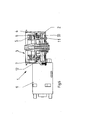
- a grinder 1 for regrind, especially coffee beans is shown in general.
- the grinder 1 has a housing 2, which has in the position of use above a filling opening 3 for ground material.
- a rotatably mounted grinding disc holder 4 is provided, on which a first annular grinding disc 5 is fixed.
- a second annular grinding disc 6 is arranged, which is held fixed to the housing, so can not rotate.
- the grinding gap is formed, is ground in the ground material, which is then discharged radially outwards due to the centrifugal forces. In this case, the ground material passes into an annular channel 7. It is dropped from this annular channel via a discharge bar 8.
- the housing 2 From the housing 2 is a discharge opening to the barge 8 from.
- an electric motor 9 is provided in a conventional manner, which is coupled via a worm drive with the grinding disc holder 4 in order to offset this in rotary motion.
- the housing 4 is circular in plan view.
- an angular bearing 11 is disposed between the grinding disc holder 4 and a housing part 10. This is arranged so that it is positioned immediately below the annular grinding discs 5,6.
- the angular contact bearing 11 is designed as an angular contact ball bearing, so that it can absorb both axial and radial forces.
- the angular contact bearing 11 is annular.
- An outer bearing shell is supported on the housing 2 and the housing part 10, while the inner bearing shell is positioned on components of the grinding disk holder 4.
- a sealing ring 12 preferably a felt ring, is provided, wherein the positioning takes place in such a manner that the sealing ring 12 bears against the underside of the grinding disc holder 4 and that radially outside of the angular bearing 11. This achieves that ground grind (flour) can not penetrate into the area in which the angular bearing 11 is arranged.
- the grinding disc holder 4 engages with an axle projection 13, the bottom of the housing, wherein the axle projection 13 in a fixed to the housing
- Bearing bush 14 is rotatably supported and is supported with a collar 15 with the interposition of a sliding bearing 16, for example a spring ring, on a collar 17 of the bearing bush 14.
- the gap 7 is formed for the ground flour.
- driver 18, which are fixedly connected to the grinding disc holder 4 or formed integrally therewith.
- the flour located in the gap 7 is guided to the ejection opening 19 and thus to the barge 8 upon rotation of the grinding disc holder 4.
- a Aufschnase 20 is formed or arranged on the housing 2. This causes that conveyed by the driver 18 in the gap 7 ground coffee or the like to the discharge opening 19 and the discharge barge 8 is imperatively transported.
Landscapes
- Engineering & Computer Science (AREA)
- Mechanical Engineering (AREA)
- Food Science & Technology (AREA)
- Crushing And Grinding (AREA)
- Food-Manufacturing Devices (AREA)
Description
- Die Erfindung betrifft ein Mahlwerk für Mahlgut mit einem Gehäuse, einem im Gehäuse drehbar gelagerten Mahlscheibenhalter, an dem eine erste ringförmige Mahlscheibe fixiert ist, einer im Gehäuse unverdrehbar gehaltenen zweiten ringförmigen Mahlscheibe, einer obenliegenden Gehäuseöffnung zum Einfüllen von Mahlgut, einer seitlich am Gehäuse ausgebildeten Abgabeöffnung für gemahlenes Mehl, sowie einem elektrischen Antrieb zum Drehen des Mahlscheibenhalters.
- Derartige Mahlwerke sind im Stand der Technik bekannt. Diese Mahlwerke arbeiten mit zwei Mahlscheiben, die ringförmig ausgebildet sind, wobei eine der Mahlscheiben feststeht und die andere Mahlscheibe rotiert. Sie ist mittels eines Mahlscheibenhalters mit einem elektrischen Antrieb gekoppelt. Das Mahlgut wird zentral von oben über eine Öffnung in das Gehäuse eingefüllt. In diese Öffnung ragt ein Konus des Mahlscheibenhalters, durch den das Mahlgut nach radial außen in den Spalt zwischen den Scheiben transportiert wird. Das von der Mitte her zugeführte Mahlgut wird durch die Mahlscheiben zerkleinert und durch Zentrifugalkraft nach außen in einen umlaufenden Mahlkanal befördert. Bei der Zerkleinerung von hartem Mahlgut, beispielsweise Kaffeebohnen, treten hohe impulsartige Belastungen zwischen den Mahlscheiben auf, die durch die Mahlscheiben und deren Lagerung aufgenommen werden müssen. Diese hohe Belastung darf nicht zu einer Bewegung der Scheiben voneinander weg führen, da sich dann zumindest zeitweise der Scheibenabstand und damit der Mahlgrad ändert. Zur Vermeidung von Verstopfungen und Überhitzung muss ebenso sichergestellt sein, dass der umlaufende Mahlgutkanal konstant entleert wird, da sich das Mahlgut ansonsten überhitzt und sich der Mahlgrad ebenfalls ändern kann, da das Mahlgut zu lange zwischen den Mahlscheiben verweilt.
- Im Stand der Technik ist es üblich, den rotierenden Mahlscheibenträger mittig jeweils mit einem Axiallager und einem Radiallager zu führen und zu lagern. Diese mittige Anordnung der Lager führt prinzipbedingt dazu, dass ein großer Hebelarm zwischen dem Lager und dem Mahlbereich zwischen den Mahlscheiben gebildet wird, so dass es durch die beim Mahlen der Bohnen auftretende Belastung zu einer starken Biegung des Mahlscheibenträgers kommt. Dies wiederum führt in Verbindung mit einem unvermeidlichen Spiel in den Lagern zu Schwankungen im Mahlscheibenabstand und damit einhergehend zu unerwünschten Schwankungen im Mahlgrad des Mahlgutes. Zudem wird insbesondere die bewegliche Mahlscheibe durch die Biegebelastung stark mechanisch beansprucht, was im ungünstigsten Fall zum Brechen der Mahlscheiben führen kann. Um dies zu vermeiden, wurden übliche Mahlwerke und -scheiben bisher aus relativ teuren Werkstoffen hoher Festigkeit (Metall) hergestellt, die aufwändig mechanisch zu bearbeiten sind. Zur Vermeidung von Verstopfungen im umlaufenden Mahlgutkanal wurde dieser großvolumig gestaltet, was dazu führt, dass das Mahlgut bei seltener Benutzung lange in dem Mahlgutkanal verweilt. Das Mahlgut, beispielsweise Kaffeemehl, verliert dadurch schnell an Aroma und der Kaffee schmeckt unangenehm.
- Aus der
CH 339709 A DE 91 15 709 U1 eine Mühle, insbesondere Getreidemühle für den Haushalt bekannt. - Ausgehend von diesem Stand der Technik liegt der Erfindung die Aufgabe zugrunde, ein Mahlwerk gattungsgemäßer Art zu schaffen, bei dem Biegebelastungen der Mahlscheiben weitestgehend vermieden sind und ein gleich bleibender Mahlgrad des Mahlgutes erreicht wird. Zudem soll der Abtransport des Mahlgutes aus dem Mahlgutkanal möglichst kontinuierlich erfolgen und Reste sollen im Mahlgutkanal nicht verbleiben.
- Zur Lösung dieser Aufgabe wird vorgeschlagen, dass zwischen Mahlscheibenhalter und einem Gehäuseteil ein Schräglager angeordnet ist, und zwar vertikal oder axial unterhalb der ringförmigen Mahlscheiben, wobei der Mahlscheibenhalter mit einem Achsvorsprung den Boden des Gehäuses durchgreift, wobei der Achsvorsprung in einer gehäusefesten Lagerbuchse gelagert ist, und sich mit einem Kragen unter Zwischenanordnung eines Gleitlagers, an einem Kragen der Lagerbuchse axial abstützt.
- Dadurch, dass die Schräglager unmittelbar unterhalb der ringförmigen Mahlscheiben angeordnet sind, also nicht mittig, sondern relativ weit radial außen liegend, wird erreicht, dass die Mahlscheiben beim Betrieb des Mahlwerkes unmittelbar durch das Lager gestützt sind, so dass eine vorzügliche Lagerung erreicht wird, bei der Schwankungen in der Mahlschlitzbreite zwischen den Scheiben vermieden werden. Im Ergebnis wird damit ein gleichmäßigeres Mehl beim Mahlen erzeugt. Zudem führt diese Ausbildung dazu, dass Biegebelastungen des Mahlscheibenhalters und der Mahlscheiben vermieden werden, was zu längerer Lebensdauer und störungssicherem Betrieb führt. Auch erlauben es diese Maßnahmen, dass das Mahlwerk bei besserer Mahlgradkonstanz kleiner, leichter und/oder aus günstigeren Materialien gefertigt werden kann.
- Um einen guten Gleichlauf des Mahlwerkes sicherzustellen und eine exakte Führung des Mahlscheibenhalters zu gewährleisten, ist vorgesehen, dass der Mahlscheibenhalter mit einem Achsvorsprung den Boden des Gehäuses durchgreift, wobei der Achsvorsprung in einer gehäusefesten Lagerbuchse gelagert ist, und sich mit einem Kragen unter Zwischenanordnung eines Gleitlagers, z.B. eines Federringes, an einem Kragen der Lagerbuchse axial abstützt.
- Hierdurch wird der Gleichlauf des Mahlwerkes gefördert.
- Insbesondere kann bevorzugt vorgesehen sein, dass das Gleitlager durch einen Federring gebildet ist.
- Vorzugsweise ist dabei vorgesehen, dass das Schräglager als Schrägkugellager ausgebildet ist.
- Zudem ist bevorzugt vorgesehen, dass das Schräglager ringförmig ausgebildet ist.
- Die Schräglager sind so ausgebildet und ausgewählt, dass sowohl axiale als auch radiale Kräfte problemlos aufgenommen werden können.
- Um zu vermeiden, dass Mahlgut in den Bereich der Lageranordnung gerät, ist vorgesehen, dass im Gehäuse ein Dichtring, vorzugsweise ein Filzring, an einer Gehäusefläche vorgesehen ist, die der Unterseite des Mahlscheibenhalters benachbart ist und bezogen auf diesen radial außen, außerhalb des Schräglagers ausgebildet ist.
- Dabei kann besonders bevorzugt vorgesehen sein, dass das der Dichtring in einer Ringnut angeordnet ist.
- Zudem kann dabei besonders bevorzugt vorgesehen sein, dass das der Dichtring aus einem Filzring besteht.
- Dieser Dichtring, insbesondere Filzring, schützt das Lager gegen den Eintritt von gemahlenem Mahlgut.
- Um einen guten und vollständigen Abtransport des Mahlgutes zu erreichen ist vorgesehen, dass radial außen zwischen den Mahlscheiben und dem Gehäuse ein Spalt für das gemahlene Mehl ausgebildet ist, dass in den Spalt Mitnehmer eingreifen, die fest mit dem Mahlscheibenhalter verbunden oder einstückig mit diesem ausgebildet sind, mittels derer bei Drehung des Mahlscheibenhalters das im Spalt befindliche Mehl zu einer Auswurföffnung des Gehäuses transportierbar ist.
- Zum Abtransport des Mahlgutes sind am Mahlscheibenträger entsprechende Mitnehmernasen ausgebildet, mittels derer das Mahlgut im Kanal gefördert wird, bis es an der Auswurföffnung abgegeben wird. Durch diese Ausbildung kann der Spalt relativ klein bemessen werden, wobei dennoch ein guter Abtransport des Mahlgutes und ein vollständiger Abtransport des Mahlgutes erreicht wird.
- Bevorzugt ist dabei vorgesehen, dass in Drehrichtung des Mahlscheibenhalters unmittelbar hinter der Auswurföffnung eine Auswurfnase oder - fläche am Gehäuse ausgebildet oder angeordnet ist.
- Hierdurch wird das mittels der Mitnehmer zur Abwurföffnung transportierte Mahlgut mit hoher Sicherheit zu der Auswurföffnung geführt, da die Auswurfnase oder Auswurffläche das durch die Mitnehmer mitgenommene Mahlgut zum Auslass, also zur Auswurföffnung hin transportiert. Durch diese Ausbildung wird ein verbesserter Abtransport erreicht, so dass jederzeit frisches Mahlgut geliefert wird und keine Verstopfungen, Überhitzungen oder Übermahlungen durch in dem Spalt verbleibendes Mahlgut bewirkt wird.
- Ein Ausführungsbeispiel der Erfindung ist in der Zeichnung dargestellt und im Folgenden näher beschrieben.
- Es zeigt:
- Figur 1
- wesentliche Bestandteile eines Mahlwerkes in Ansicht;
- Figur 2
- ein erfindungsgemäßes Mahlwerk nebst zugehöriger Komponenten in Draufsicht gesehen;
- Figur 3
- desgleichen im Schnitt III-III der
Figur 2 gesehen; - Figur 4
- eine Ansicht analog
Figur 1 gesehen; - Figur 5
- das Mahlwerk gemäß
Figur 4 in Draufsicht gesehen; - Figur 6
- desgleichen im Schnitt VI-VI der
Figur 5 gesehen; - Figur 7
- desgleichen im Schnitt VII-VII der
Figur 5 gesehen. - In der Zeichnung ist ganz allgemein ein Mahlwerk 1 für Mahlgut, insbesondere Kaffeebohnen gezeigt. Das Mahlwerk 1 weist ein Gehäuse 2 auf, welches in Gebrauchslage oben eine Einfüllöffnung 3 für Mahlgut aufweist. Im Gehäuse 2 ist ein drehbar gelagerter Mahlscheibenhalter 4 vorgesehen, an dem eine erste ringförmige Mahlscheibe 5 befestigt ist. Oberhalb dieser mit dem Mahlscheibenhalter 4 drehbaren ersten Mahlscheibe 5 ist eine zweite ringförmige Mahlscheibe 6 angeordnet, die gehäusefest gehalten ist, also nicht mitdrehen kann. Zwischen den beiden Mahlscheiben 5,6 ist der Mahlspalt gebildet, in dem Mahlgut gemahlen wird, welches dann aufgrund der Zentrifugalkräfte nach radial außen abgefördert wird. Dabei gelangt das Mahlgut in einen Ringkanal 7. Es wird aus diesem Ringkanal über eine Abgabeschute 8 abgeworfen. Vom Gehäuse 2 geht eine Abgabeöffnung an die Schute 8 ab. Zum Betrieb des Mahlwerkes ist in an sich bekannter Art und Weise ein Elektromotor 9 vorgesehen, der über einen Schneckenantrieb mit dem Mahlscheibenhalter 4 gekoppelt ist, um diesen in Drehbewegung zu versetzten. Das Gehäuse 4 ist in Draufsicht kreisrund ausgebildet.
- Gemäß der Erfindung ist zwischen dem Mahlscheibenhalter 4 und einem Gehäuseteil 10 ein Schräglager 11 angeordnet. Dieses ist derart angeordnet, dass es unmittelbar unterhalb der ringförmigen Mahlscheiben 5,6 positioniert ist. Das Schräglager 11 ist als Schrägkugellager ausgebildet, so dass es sowohl axiale als auch radiale Kräfte aufnehmen kann. Im Übrigen ist das Schräglager 11 ringförmig ausgebildet. Eine äußere Lagerschale stützt sich am Gehäuse 2 und dem Gehäuseteil 10 ab, während die innere Lagerschale an Bestandteilen des Mahlscheibenhalters 4 positioniert ist. Durch diese Anordnung wird erreicht, dass beim Betrieb des Mahlwerkes 1 keine wesentlichen Biegekräfte auf die Mahlscheiben 5,6 bzw. den Mahlscheibenhalter 4 einwirken, da die beim Mahlen des Mahlgutes auftretenden Kräfte von dem Schräglager 11 abgefangen werden. Die sich hieraus ergebenden Vorteile sind in der vorangehenden Beschreibung erörtert.
- Zusätzlich ist im Gehäuse 2 in einer entsprechenden Ringnut ein Dichtring 12, vorzugsweise ein Filzring, vorgesehen, wobei die Positionierung in der Weise erfolgt, dass der Dichtring 12 an der Unterseite des Mahlscheibenhalters 4 anliegt und zwar radial außerhalb des Schräglagers 11. Hierdurch wird erreicht, dass aufgemahlenes Mahlgut (Mehl) nicht in den Bereich eindringen kann, in dem das Schräglager 11 angeordnet ist.
- Der Mahlscheibenhalter 4 durchgreift mit einem Achsvorsprung 13 den Boden des Gehäuses, wobei der Achsvorsprung 13 in einer gehäusefesten Lagerbuchse 14 drehbar gelagert ist und sich mit einem Kragen 15 unter Zwischenanordnung eines Gleitlagers 16, beispielsweise eines Federrings, an einem Kragen 17 der Lagerbuchse 14 abstützt.
- Radial außen zwischen den Mahlscheiben 5,6 und dem Gehäuse 2 ist der Spalt 7 für das gemahlene Mehl ausgebildet. In den Spalt 7 greifen Mitnehmer 18 ein, die fest mit dem Mahlscheibenhalter 4 verbunden oder einstückig mit diesem ausgebildet sind. Mittels dieser Mitnehmer 18 wird bei Drehung des Mahlscheibenhalters 4 das im Spalt 7 befindliche Mehl zu der Auswurföffnung 19 und damit zu der Schute 8 geführt.
- In Drehrichtung des Mahlscheibenhalters 4 hinter der Auswurföffnung 19 ist eine Aufwurfnase 20 am Gehäuse 2 ausgebildet oder angeordnet. Diese bewirkt, dass das durch die Mitnehmer 18 in dem Spalt 7 geförderte Kaffeemehl oder dergleichen zur Auswurföffnung 19 und zur Abgabeschute 8 zwingend transportiert wird.
- Die Erfindung ist nicht auf das Ausführungsbeispiel beschränkt, sondern im Rahmen der Offenbarung vielfach variabel.
Claims (9)
- Mahlwerk (1) für Mahlgut mit einem Gehäuse (2), einem im Gehäuse (2) drehbar gelagerten Mahlscheibenhalter (4), an dem eine erste ringförmige Mahlscheibe (5) fixiert ist, einer im Gehäuse (2) unverdrehbar gehaltenen zweiten ringförmigen Mahlscheibe (6), einer obenliegenden Gehäuseöffnung (3) zum Einfüllen von Mahlgut, einer seitlich am Gehäuse ausgebildeten Abgabeöffnung (19) für gemahlenes Mehl, sowie einem elektrischen Antrieb (9) zum Drehen des Mahlscheibenhalters (4), dadurch gekennzeichnet, dass zwischen Mahlscheibenhalter (4) und einem Gehäuseteil (10) ein Schräglager (11) angeordnet ist, und zwar vertikal oder axial unterhalb der ringförmigen Mahlscheiben (5,6), wobei der Mahlscheibenhalter (4) mit einem Achsvorsprung (13) den Boden des Gehäuses (2) durchgreift, wobei der Achsvorsprung (13) in einer gehäusefesten Lagerbuchse (14) gelagert ist, und sich mit einem Kragen (15) unter Zwischenanordnung eines Gleitlagers (16), an einem Kragen (17) der Lagerbuchse (14) axial abstützt.
- Mahlwerk nach Anspruch 1, dadurch gekennzeichnet, dass das Gleitlager (16) durch einen Federring gebildet ist.
- Mahlwerk nach Anspruch 1 oder 2, dadurch gekennzeichnet, dass das Schräglager (11) als Schrägkugellager ausgebildet ist.
- Mahlwerk nach einem der Ansprüche 1 bis 3, dadurch gekennzeichnet, dass das Schräglager (11) ringförmig ausgebildet ist.
- Mahlwerk nach einem der Ansprüche 1 bis 4, dadurch gekennzeichnet, dass im Gehäuse (2) ein Dichtring (12), vorzugsweise ein Filzring, an einer Gehäusefläche vorgesehen ist, die der Unterseite des Mahlscheibenhalters (4) benachbart ist und bezogen auf diesen radial außen, außerhalb des Schräglagers (11) ausgebildet ist.
- Mahlwerk nach Anspruch 5, dadurch gekennzeichnet, dass das der Dichtring (12) in einer Ringnut angeordnet ist.
- Mahlwerk nach Anspruch 5 oder 6, dadurch gekennzeichnet, dass das der Dichtring (12) aus einem Filzring besteht.
- Mahlwerk nach einem der Ansprüche 1 bis 7, dadurch gekennzeichnet, dass radial außen zwischen den Mahlscheiben (5,6) und dem Gehäuse (2) ein Spalt (7) für das gemahlene Mehl ausgebildet ist, dass in den Spalt (7) Mitnehmer (18) eingreifen, die fest mit dem Mahlscheibenhalter (4) verbunden oder einstückig mit diesem ausgebildet sind, mittels derer bei Drehung des Mahlscheibenhalters (4) das im Spalt (7) befindliche Mehl zu einer Auswurföffnung (19) des Gehäuses (2) transportierbar ist.
- Mahlwerk nach Anspruch 8, dadurch gekennzeichnet, dass in Drehrichtung des Mahlscheibenhalters (4) unmittelbar hinter der Auswurföffnung (19) eine Auswurfnase (20) oder -fläche am Gehäuse (2) ausgebildet oder angeordnet ist.
Applications Claiming Priority (1)
| Application Number | Priority Date | Filing Date | Title |
|---|---|---|---|
| DE102010017721A DE102010017721A1 (de) | 2010-07-05 | 2010-07-05 | Mahlwerk |
Publications (2)
| Publication Number | Publication Date |
|---|---|
| EP2404534A1 EP2404534A1 (de) | 2012-01-11 |
| EP2404534B1 true EP2404534B1 (de) | 2014-08-13 |
Family
ID=43218060
Family Applications (1)
| Application Number | Title | Priority Date | Filing Date |
|---|---|---|---|
| EP11004563.0A Active EP2404534B1 (de) | 2010-07-05 | 2011-06-04 | Mahlwerk |
Country Status (7)
| Country | Link |
|---|---|
| US (1) | US20120001005A1 (de) |
| EP (1) | EP2404534B1 (de) |
| CN (1) | CN102343293B (de) |
| AU (1) | AU2011202903A1 (de) |
| BR (1) | BRPI1103564A2 (de) |
| CA (1) | CA2744661A1 (de) |
| DE (1) | DE102010017721A1 (de) |
Families Citing this family (13)
| Publication number | Priority date | Publication date | Assignee | Title |
|---|---|---|---|---|
| ATE541492T1 (de) * | 2009-08-21 | 2012-02-15 | Schaerer Ag | Mahlwerk für eine kaffeemaschine |
| AU2013319825B2 (en) * | 2012-09-21 | 2018-07-19 | Koninklijke Douwe Egberts B.V. (Utrecht) | Coffee grinder and coffee machine containing a coffee grinder |
| EP2764807A1 (de) * | 2013-02-12 | 2014-08-13 | Jura Elektroapparate AG | Mahlwerk |
| WO2015089567A1 (en) * | 2013-12-20 | 2015-06-25 | Van Deuce Pty Ltd | Coffee grinder |
| CN104971793A (zh) * | 2015-05-21 | 2015-10-14 | 常州大学 | 一种电动磨盘式黄豆加工装置 |
| PL3114975T3 (pl) * | 2015-07-10 | 2019-02-28 | Jura Elektroapparate Ag | Urządzenie mielące do ekspresów do kawy |
| DE102016103806B4 (de) * | 2016-03-03 | 2019-01-17 | Eugster / Frismag Ag | Kaffeemühle sowie Kaffeevollautomat mit Kaffeemühle |
| TWI735654B (zh) * | 2016-09-19 | 2021-08-11 | 義大利商辛巴利集團公司 | 用於適用製造飲料之植物性產品,尤其是烤咖啡豆的研磨裝置之研磨室 |
| EP3581078A1 (de) * | 2018-06-14 | 2019-12-18 | Jura Elektroapparate AG | Mahlvorrichtung zum mahlen von kaffeebohnen |
| EP3996559A1 (de) | 2019-07-11 | 2022-05-18 | Creatrix AG | Einheit einer kaffeevorrichtung |
| CN114786548B (zh) * | 2019-12-18 | 2024-12-31 | 美乐家专业咖啡解决方案有限两合公司 | 碾磨机、碾磨机的碾磨盘片和具有这种碾磨机的咖啡机 |
| CN115736649B (zh) * | 2022-11-24 | 2025-10-14 | 广东新功电器有限公司 | 一种电饭锅盖打开和关闭方法 |
| CN118341525B (zh) * | 2024-05-14 | 2026-05-12 | 广西昭平县将军峰农业科技有限公司 | 一种茶叶湿式粉碎机 |
Family Cites Families (16)
| Publication number | Priority date | Publication date | Assignee | Title |
|---|---|---|---|---|
| US1415808A (en) * | 1922-05-09 | dellinger | ||
| US1969899A (en) * | 1933-02-15 | 1934-08-14 | Hamilton Beach Mfg Company | Coffee grinder attachment |
| US2255071A (en) * | 1939-05-04 | 1941-09-09 | Marco Company Inc | Disk mill |
| US2572373A (en) * | 1946-02-28 | 1951-10-23 | Niethamer Julius | Grinding disk or pulverizer |
| US2852202A (en) * | 1954-04-28 | 1958-09-16 | Ditting | Coffee grinder |
| CH339709A (de) * | 1956-04-13 | 1959-07-15 | Benz Ag Fabrik Elektrischer Ma | Mühle mit vertikaler Welle zum Mahlen von Kaffee und dergleichen |
| US2968444A (en) * | 1956-11-07 | 1961-01-17 | Ed Jones Corp | Refining discs |
| IT1034846B (it) * | 1975-04-04 | 1979-10-10 | Pozzato Tarcisio | Dispositivo di regolazione per mulino a dischi per mulino a dischi per ghiaia e simili |
| US4039153A (en) * | 1976-04-26 | 1977-08-02 | Hoffman Douglas L | Grinding mill |
| EP0324357B1 (de) * | 1988-01-09 | 1993-05-19 | C. & E. FEIN GmbH & Co. | Einrichtung zum Spannen eines scheibenförmigen Werkzeugs |
| IT1226095B (it) * | 1988-07-06 | 1990-12-10 | Lucio Grossi | Dispositivo di macinazione per caffe'. |
| CN2057862U (zh) * | 1989-07-01 | 1990-06-06 | 胡明厚 | 立式磨浆机 |
| US5058814A (en) * | 1989-08-16 | 1991-10-22 | Modern Process Equipment, Inc. | Coffee grinder |
| US5172868A (en) * | 1991-10-24 | 1992-12-22 | Bunn-O-Matic Corporation | Home coffee grinder |
| DE9115709U1 (de) * | 1991-12-18 | 1992-03-26 | Bosch-Siemens Hausgeräte GmbH, 8000 München | Mühle, insbesondere Getreidemühle für den Haushalt |
| CN201493130U (zh) * | 2009-08-12 | 2010-06-02 | 商安平 | 一种自分离磨浆机防漏装置 |
-
2010
- 2010-07-05 DE DE102010017721A patent/DE102010017721A1/de not_active Withdrawn
-
2011
- 2011-06-04 EP EP11004563.0A patent/EP2404534B1/de active Active
- 2011-06-17 AU AU2011202903A patent/AU2011202903A1/en not_active Abandoned
- 2011-06-28 US US13/170,219 patent/US20120001005A1/en not_active Abandoned
- 2011-06-29 CA CA2744661A patent/CA2744661A1/en not_active Abandoned
- 2011-07-04 BR BRPI1103564-1A patent/BRPI1103564A2/pt not_active IP Right Cessation
- 2011-07-05 CN CN201110186290.XA patent/CN102343293B/zh active Active
Also Published As
| Publication number | Publication date |
|---|---|
| AU2011202903A1 (en) | 2012-01-19 |
| BRPI1103564A2 (pt) | 2012-11-20 |
| CA2744661A1 (en) | 2012-01-05 |
| US20120001005A1 (en) | 2012-01-05 |
| EP2404534A1 (de) | 2012-01-11 |
| CN102343293B (zh) | 2015-03-18 |
| DE102010017721A1 (de) | 2010-12-30 |
| CN102343293A (zh) | 2012-02-08 |
Similar Documents
| Publication | Publication Date | Title |
|---|---|---|
| EP2404534A1 (de) | Mahlwerk | |
| EP2984973A1 (de) | Mahlwerk zum Mahlen von Kaffeebohnen sowie Kaffeemaschine mit einem solchen Mahlwerk | |
| EP3202290B1 (de) | Mahlwerk, mühle, kaffeezubereitungsvorrichtung mit mühle sowie mahlverfahren | |
| EP1493368A1 (de) | Kaffeemühle für eine Kaffeemaschine | |
| DE2448013C2 (de) | Getreidemühle | |
| DE2519848C2 (de) | Handmühle zum Herstellen von Mehlen aus pflanzlichen Produkten | |
| DE7232746U (de) | Kugel- oder rollenmuehle zum zerkleinern von kakao schokolade farbpigmenten emaille und dgl. | |
| DE2809609C2 (de) | Schneidsatz für Fleischwölfe | |
| DE69903021T2 (de) | Mühle zur zerkleinerung von schüttgut | |
| DE4431960C1 (de) | Messer für Fleischwölfe | |
| EP3383542B1 (de) | Mahlsteinanordnung für ein scheibenmahlwerk zur zerkleinerung von mahlgut | |
| DE2436482C3 (de) | Motorbetätigte Mühle für den Haushalt zur Zerkleinerung von trockenem, körnigem Mahlgut, insbesondere Getreide | |
| DE3021368A1 (de) | Haushalt-getreidemuehle | |
| EP1163084A1 (de) | Schleifmaschine | |
| DE102016216332B4 (de) | Scheibenmahlwerk für Kaffeevollautomat | |
| EP3192414B1 (de) | Kaffeebohnen-mahlwerk für kaffeezubereitungsvorrichtung sowie kaffeezubereitungsvorrichtung | |
| DE494489C (de) | Schleifvorrichtung fuer Sichelmesser bei Strangzigarettenmaschinen | |
| DE1181091B (de) | Wolf zum Zerkleinern von Fleisch und sonstigen Nahrungsmitteln | |
| DE1030218B (de) | Zerkleinerungsmaschine fuer Fleisch und aehnliche Produkte | |
| DE69008686T2 (de) | Pulverisiermühle. | |
| DE2554111C2 (de) | Durchlaufbrecher für Kettenkratzförderer, vorzugsweise des Untertagebetriebes | |
| DE645522C (de) | Vorrichtung zum Zerkleinern von Mahlgut | |
| CH666629A5 (en) | Mill for grinding granular material - has stationary and rotating discs with raised cutting edges | |
| DE670606C (de) | Mahlgang oder Scheibenmuehle | |
| DE2444152A1 (de) | Mahlsteinpaar fuer eine getreidemuehle |
Legal Events
| Date | Code | Title | Description |
|---|---|---|---|
| AK | Designated contracting states |
Kind code of ref document: A1 Designated state(s): AL AT BE BG CH CY CZ DE DK EE ES FI FR GB GR HR HU IE IS IT LI LT LU LV MC MK MT NL NO PL PT RO RS SE SI SK SM TR |
|
| AX | Request for extension of the european patent |
Extension state: BA ME |
|
| PUAI | Public reference made under article 153(3) epc to a published international application that has entered the european phase |
Free format text: ORIGINAL CODE: 0009012 |
|
| 17P | Request for examination filed |
Effective date: 20120602 |
|
| GRAP | Despatch of communication of intention to grant a patent |
Free format text: ORIGINAL CODE: EPIDOSNIGR1 |
|
| GRAJ | Information related to disapproval of communication of intention to grant by the applicant or resumption of examination proceedings by the epo deleted |
Free format text: ORIGINAL CODE: EPIDOSDIGR1 |
|
| GRAP | Despatch of communication of intention to grant a patent |
Free format text: ORIGINAL CODE: EPIDOSNIGR1 |
|
| INTG | Intention to grant announced |
Effective date: 20140403 |
|
| RIC1 | Information provided on ipc code assigned before grant |
Ipc: A47J 31/42 20060101AFI20140324BHEP Ipc: A47J 42/16 20060101ALI20140324BHEP |
|
| INTG | Intention to grant announced |
Effective date: 20140414 |
|
| GRAS | Grant fee paid |
Free format text: ORIGINAL CODE: EPIDOSNIGR3 |
|
| GRAA | (expected) grant |
Free format text: ORIGINAL CODE: 0009210 |
|
| AK | Designated contracting states |
Kind code of ref document: B1 Designated state(s): AL AT BE BG CH CY CZ DE DK EE ES FI FR GB GR HR HU IE IS IT LI LT LU LV MC MK MT NL NO PL PT RO RS SE SI SK SM TR |
|
| REG | Reference to a national code |
Ref country code: GB Ref legal event code: FG4D Free format text: NOT ENGLISH |
|
| REG | Reference to a national code |
Ref country code: AT Ref legal event code: REF Ref document number: 681613 Country of ref document: AT Kind code of ref document: T Effective date: 20140815 Ref country code: CH Ref legal event code: NV Representative=s name: TROESCH SCHEIDEGGER WERNER AG, CH Ref country code: CH Ref legal event code: EP |
|
| REG | Reference to a national code |
Ref country code: IE Ref legal event code: FG4D Free format text: LANGUAGE OF EP DOCUMENT: GERMAN |
|
| REG | Reference to a national code |
Ref country code: DE Ref legal event code: R096 Ref document number: 502011004002 Country of ref document: DE Effective date: 20140925 |
|
| REG | Reference to a national code |
Ref country code: NL Ref legal event code: VDEP Effective date: 20140813 |
|
| REG | Reference to a national code |
Ref country code: LT Ref legal event code: MG4D |
|
| PG25 | Lapsed in a contracting state [announced via postgrant information from national office to epo] |
Ref country code: GR Free format text: LAPSE BECAUSE OF FAILURE TO SUBMIT A TRANSLATION OF THE DESCRIPTION OR TO PAY THE FEE WITHIN THE PRESCRIBED TIME-LIMIT Effective date: 20141114 Ref country code: LT Free format text: LAPSE BECAUSE OF FAILURE TO SUBMIT A TRANSLATION OF THE DESCRIPTION OR TO PAY THE FEE WITHIN THE PRESCRIBED TIME-LIMIT Effective date: 20140813 Ref country code: ES Free format text: LAPSE BECAUSE OF FAILURE TO SUBMIT A TRANSLATION OF THE DESCRIPTION OR TO PAY THE FEE WITHIN THE PRESCRIBED TIME-LIMIT Effective date: 20140813 Ref country code: NO Free format text: LAPSE BECAUSE OF FAILURE TO SUBMIT A TRANSLATION OF THE DESCRIPTION OR TO PAY THE FEE WITHIN THE PRESCRIBED TIME-LIMIT Effective date: 20141113 Ref country code: FI Free format text: LAPSE BECAUSE OF FAILURE TO SUBMIT A TRANSLATION OF THE DESCRIPTION OR TO PAY THE FEE WITHIN THE PRESCRIBED TIME-LIMIT Effective date: 20140813 Ref country code: PT Free format text: LAPSE BECAUSE OF FAILURE TO SUBMIT A TRANSLATION OF THE DESCRIPTION OR TO PAY THE FEE WITHIN THE PRESCRIBED TIME-LIMIT Effective date: 20141215 Ref country code: BG Free format text: LAPSE BECAUSE OF FAILURE TO SUBMIT A TRANSLATION OF THE DESCRIPTION OR TO PAY THE FEE WITHIN THE PRESCRIBED TIME-LIMIT Effective date: 20141113 Ref country code: SE Free format text: LAPSE BECAUSE OF FAILURE TO SUBMIT A TRANSLATION OF THE DESCRIPTION OR TO PAY THE FEE WITHIN THE PRESCRIBED TIME-LIMIT Effective date: 20140813 |
|
| PG25 | Lapsed in a contracting state [announced via postgrant information from national office to epo] |
Ref country code: RS Free format text: LAPSE BECAUSE OF FAILURE TO SUBMIT A TRANSLATION OF THE DESCRIPTION OR TO PAY THE FEE WITHIN THE PRESCRIBED TIME-LIMIT Effective date: 20140813 Ref country code: LV Free format text: LAPSE BECAUSE OF FAILURE TO SUBMIT A TRANSLATION OF THE DESCRIPTION OR TO PAY THE FEE WITHIN THE PRESCRIBED TIME-LIMIT Effective date: 20140813 Ref country code: IS Free format text: LAPSE BECAUSE OF FAILURE TO SUBMIT A TRANSLATION OF THE DESCRIPTION OR TO PAY THE FEE WITHIN THE PRESCRIBED TIME-LIMIT Effective date: 20141213 Ref country code: HR Free format text: LAPSE BECAUSE OF FAILURE TO SUBMIT A TRANSLATION OF THE DESCRIPTION OR TO PAY THE FEE WITHIN THE PRESCRIBED TIME-LIMIT Effective date: 20140813 Ref country code: CY Free format text: LAPSE BECAUSE OF FAILURE TO SUBMIT A TRANSLATION OF THE DESCRIPTION OR TO PAY THE FEE WITHIN THE PRESCRIBED TIME-LIMIT Effective date: 20140813 |
|
| PG25 | Lapsed in a contracting state [announced via postgrant information from national office to epo] |
Ref country code: NL Free format text: LAPSE BECAUSE OF FAILURE TO SUBMIT A TRANSLATION OF THE DESCRIPTION OR TO PAY THE FEE WITHIN THE PRESCRIBED TIME-LIMIT Effective date: 20140813 |
|
| PG25 | Lapsed in a contracting state [announced via postgrant information from national office to epo] |
Ref country code: DK Free format text: LAPSE BECAUSE OF FAILURE TO SUBMIT A TRANSLATION OF THE DESCRIPTION OR TO PAY THE FEE WITHIN THE PRESCRIBED TIME-LIMIT Effective date: 20140813 Ref country code: EE Free format text: LAPSE BECAUSE OF FAILURE TO SUBMIT A TRANSLATION OF THE DESCRIPTION OR TO PAY THE FEE WITHIN THE PRESCRIBED TIME-LIMIT Effective date: 20140813 Ref country code: SK Free format text: LAPSE BECAUSE OF FAILURE TO SUBMIT A TRANSLATION OF THE DESCRIPTION OR TO PAY THE FEE WITHIN THE PRESCRIBED TIME-LIMIT Effective date: 20140813 Ref country code: CZ Free format text: LAPSE BECAUSE OF FAILURE TO SUBMIT A TRANSLATION OF THE DESCRIPTION OR TO PAY THE FEE WITHIN THE PRESCRIBED TIME-LIMIT Effective date: 20140813 Ref country code: RO Free format text: LAPSE BECAUSE OF FAILURE TO SUBMIT A TRANSLATION OF THE DESCRIPTION OR TO PAY THE FEE WITHIN THE PRESCRIBED TIME-LIMIT Effective date: 20140813 |
|
| REG | Reference to a national code |
Ref country code: DE Ref legal event code: R097 Ref document number: 502011004002 Country of ref document: DE |
|
| PG25 | Lapsed in a contracting state [announced via postgrant information from national office to epo] |
Ref country code: PL Free format text: LAPSE BECAUSE OF FAILURE TO SUBMIT A TRANSLATION OF THE DESCRIPTION OR TO PAY THE FEE WITHIN THE PRESCRIBED TIME-LIMIT Effective date: 20140813 |
|
| PLBE | No opposition filed within time limit |
Free format text: ORIGINAL CODE: 0009261 |
|
| STAA | Information on the status of an ep patent application or granted ep patent |
Free format text: STATUS: NO OPPOSITION FILED WITHIN TIME LIMIT |
|
| 26N | No opposition filed |
Effective date: 20150515 |
|
| PG25 | Lapsed in a contracting state [announced via postgrant information from national office to epo] |
Ref country code: SI Free format text: LAPSE BECAUSE OF FAILURE TO SUBMIT A TRANSLATION OF THE DESCRIPTION OR TO PAY THE FEE WITHIN THE PRESCRIBED TIME-LIMIT Effective date: 20140813 |
|
| PG25 | Lapsed in a contracting state [announced via postgrant information from national office to epo] |
Ref country code: MC Free format text: LAPSE BECAUSE OF FAILURE TO SUBMIT A TRANSLATION OF THE DESCRIPTION OR TO PAY THE FEE WITHIN THE PRESCRIBED TIME-LIMIT Effective date: 20140813 |
|
| PG25 | Lapsed in a contracting state [announced via postgrant information from national office to epo] |
Ref country code: LU Free format text: LAPSE BECAUSE OF FAILURE TO SUBMIT A TRANSLATION OF THE DESCRIPTION OR TO PAY THE FEE WITHIN THE PRESCRIBED TIME-LIMIT Effective date: 20150604 |
|
| REG | Reference to a national code |
Ref country code: IE Ref legal event code: MM4A |
|
| PG25 | Lapsed in a contracting state [announced via postgrant information from national office to epo] |
Ref country code: IE Free format text: LAPSE BECAUSE OF NON-PAYMENT OF DUE FEES Effective date: 20150604 |
|
| REG | Reference to a national code |
Ref country code: FR Ref legal event code: PLFP Year of fee payment: 6 |
|
| PG25 | Lapsed in a contracting state [announced via postgrant information from national office to epo] |
Ref country code: MT Free format text: LAPSE BECAUSE OF FAILURE TO SUBMIT A TRANSLATION OF THE DESCRIPTION OR TO PAY THE FEE WITHIN THE PRESCRIBED TIME-LIMIT Effective date: 20140813 |
|
| PG25 | Lapsed in a contracting state [announced via postgrant information from national office to epo] |
Ref country code: SM Free format text: LAPSE BECAUSE OF FAILURE TO SUBMIT A TRANSLATION OF THE DESCRIPTION OR TO PAY THE FEE WITHIN THE PRESCRIBED TIME-LIMIT Effective date: 20140813 Ref country code: HU Free format text: LAPSE BECAUSE OF FAILURE TO SUBMIT A TRANSLATION OF THE DESCRIPTION OR TO PAY THE FEE WITHIN THE PRESCRIBED TIME-LIMIT; INVALID AB INITIO Effective date: 20110604 |
|
| REG | Reference to a national code |
Ref country code: FR Ref legal event code: PLFP Year of fee payment: 7 |
|
| PG25 | Lapsed in a contracting state [announced via postgrant information from national office to epo] |
Ref country code: BE Free format text: LAPSE BECAUSE OF NON-PAYMENT OF DUE FEES Effective date: 20150630 |
|
| PG25 | Lapsed in a contracting state [announced via postgrant information from national office to epo] |
Ref country code: TR Free format text: LAPSE BECAUSE OF FAILURE TO SUBMIT A TRANSLATION OF THE DESCRIPTION OR TO PAY THE FEE WITHIN THE PRESCRIBED TIME-LIMIT Effective date: 20140813 |
|
| REG | Reference to a national code |
Ref country code: FR Ref legal event code: PLFP Year of fee payment: 8 |
|
| PG25 | Lapsed in a contracting state [announced via postgrant information from national office to epo] |
Ref country code: MK Free format text: LAPSE BECAUSE OF FAILURE TO SUBMIT A TRANSLATION OF THE DESCRIPTION OR TO PAY THE FEE WITHIN THE PRESCRIBED TIME-LIMIT Effective date: 20140813 |
|
| PG25 | Lapsed in a contracting state [announced via postgrant information from national office to epo] |
Ref country code: AL Free format text: LAPSE BECAUSE OF FAILURE TO SUBMIT A TRANSLATION OF THE DESCRIPTION OR TO PAY THE FEE WITHIN THE PRESCRIBED TIME-LIMIT Effective date: 20140813 |
|
| P01 | Opt-out of the competence of the unified patent court (upc) registered |
Effective date: 20230509 |
|
| PGFP | Annual fee paid to national office [announced via postgrant information from national office to epo] |
Ref country code: FR Payment date: 20230622 Year of fee payment: 13 |
|
| PGFP | Annual fee paid to national office [announced via postgrant information from national office to epo] |
Ref country code: AT Payment date: 20230616 Year of fee payment: 13 |
|
| PGFP | Annual fee paid to national office [announced via postgrant information from national office to epo] |
Ref country code: IT Payment date: 20230630 Year of fee payment: 13 Ref country code: GB Payment date: 20230622 Year of fee payment: 13 Ref country code: CH Payment date: 20230702 Year of fee payment: 13 |
|
| REG | Reference to a national code |
Ref country code: CH Ref legal event code: PL |
|
| REG | Reference to a national code |
Ref country code: AT Ref legal event code: MM01 Ref document number: 681613 Country of ref document: AT Kind code of ref document: T Effective date: 20240604 |
|
| GBPC | Gb: european patent ceased through non-payment of renewal fee |
Effective date: 20240604 |
|
| PG25 | Lapsed in a contracting state [announced via postgrant information from national office to epo] |
Ref country code: AT Free format text: LAPSE BECAUSE OF NON-PAYMENT OF DUE FEES Effective date: 20240604 Ref country code: CH Free format text: LAPSE BECAUSE OF NON-PAYMENT OF DUE FEES Effective date: 20240630 |
|
| PG25 | Lapsed in a contracting state [announced via postgrant information from national office to epo] |
Ref country code: FR Free format text: LAPSE BECAUSE OF NON-PAYMENT OF DUE FEES Effective date: 20240630 |
|
| PG25 | Lapsed in a contracting state [announced via postgrant information from national office to epo] |
Ref country code: GB Free format text: LAPSE BECAUSE OF NON-PAYMENT OF DUE FEES Effective date: 20240604 Ref country code: IT Free format text: LAPSE BECAUSE OF NON-PAYMENT OF DUE FEES Effective date: 20240604 |
|
| PGFP | Annual fee paid to national office [announced via postgrant information from national office to epo] |
Ref country code: DE Payment date: 20250831 Year of fee payment: 15 |
|
| REG | Reference to a national code |
Ref country code: DE Ref legal event code: R082 Ref document number: 502011004002 Country of ref document: DE Representative=s name: KOECHLING, MARIETTA, M.SC B.ENG., DE |