EP2403633B1 - Koaxialer kompaktstatikmischer sowie dessen verwendung - Google Patents
Koaxialer kompaktstatikmischer sowie dessen verwendung Download PDFInfo
- Publication number
- EP2403633B1 EP2403633B1 EP10706933.8A EP10706933A EP2403633B1 EP 2403633 B1 EP2403633 B1 EP 2403633B1 EP 10706933 A EP10706933 A EP 10706933A EP 2403633 B1 EP2403633 B1 EP 2403633B1
- Authority
- EP
- European Patent Office
- Prior art keywords
- mixing
- static mixer
- channels
- mixer according
- annular
- Prior art date
- Legal status (The legal status is an assumption and is not a legal conclusion. Google has not performed a legal analysis and makes no representation as to the accuracy of the status listed.)
- Active
Links
Images


Classifications
-
- B—PERFORMING OPERATIONS; TRANSPORTING
- B29—WORKING OF PLASTICS; WORKING OF SUBSTANCES IN A PLASTIC STATE IN GENERAL
- B29B—PREPARATION OR PRETREATMENT OF THE MATERIAL TO BE SHAPED; MAKING GRANULES OR PREFORMS; RECOVERY OF PLASTICS OR OTHER CONSTITUENTS OF WASTE MATERIAL CONTAINING PLASTICS
- B29B7/00—Mixing; Kneading
- B29B7/30—Mixing; Kneading continuous, with mechanical mixing or kneading devices
- B29B7/32—Mixing; Kneading continuous, with mechanical mixing or kneading devices with non-movable mixing or kneading devices
- B29B7/325—Static mixers
-
- B—PERFORMING OPERATIONS; TRANSPORTING
- B01—PHYSICAL OR CHEMICAL PROCESSES OR APPARATUS IN GENERAL
- B01F—MIXING, e.g. DISSOLVING, EMULSIFYING OR DISPERSING
- B01F23/00—Mixing according to the phases to be mixed, e.g. dispersing or emulsifying
- B01F23/50—Mixing liquids with solids
-
- B—PERFORMING OPERATIONS; TRANSPORTING
- B01—PHYSICAL OR CHEMICAL PROCESSES OR APPARATUS IN GENERAL
- B01F—MIXING, e.g. DISSOLVING, EMULSIFYING OR DISPERSING
- B01F25/00—Flow mixers; Mixers for falling materials, e.g. solid particles
- B01F25/40—Static mixers
- B01F25/42—Static mixers in which the mixing is affected by moving the components jointly in changing directions, e.g. in tubes provided with baffles or obstructions
- B01F25/43—Mixing tubes, e.g. wherein the material is moved in a radial or partly reversed direction
- B01F25/432—Mixing tubes, e.g. wherein the material is moved in a radial or partly reversed direction with means for dividing the material flow into separate sub-flows and for repositioning and recombining these sub-flows; Cross-mixing, e.g. conducting the outer layer of the material nearer to the axis of the tube or vice-versa
- B01F25/4321—Mixing tubes, e.g. wherein the material is moved in a radial or partly reversed direction with means for dividing the material flow into separate sub-flows and for repositioning and recombining these sub-flows; Cross-mixing, e.g. conducting the outer layer of the material nearer to the axis of the tube or vice-versa the subflows consisting of at least two flat layers which are recombined, e.g. using means having restriction or expansion zones
-
- B—PERFORMING OPERATIONS; TRANSPORTING
- B01—PHYSICAL OR CHEMICAL PROCESSES OR APPARATUS IN GENERAL
- B01F—MIXING, e.g. DISSOLVING, EMULSIFYING OR DISPERSING
- B01F25/00—Flow mixers; Mixers for falling materials, e.g. solid particles
- B01F25/40—Static mixers
- B01F25/42—Static mixers in which the mixing is affected by moving the components jointly in changing directions, e.g. in tubes provided with baffles or obstructions
- B01F25/43—Mixing tubes, e.g. wherein the material is moved in a radial or partly reversed direction
- B01F25/432—Mixing tubes, e.g. wherein the material is moved in a radial or partly reversed direction with means for dividing the material flow into separate sub-flows and for repositioning and recombining these sub-flows; Cross-mixing, e.g. conducting the outer layer of the material nearer to the axis of the tube or vice-versa
- B01F25/4323—Mixing tubes, e.g. wherein the material is moved in a radial or partly reversed direction with means for dividing the material flow into separate sub-flows and for repositioning and recombining these sub-flows; Cross-mixing, e.g. conducting the outer layer of the material nearer to the axis of the tube or vice-versa using elements provided with a plurality of channels or using a plurality of tubes which can either be placed between common spaces or collectors
- B01F25/43231—Mixing tubes, e.g. wherein the material is moved in a radial or partly reversed direction with means for dividing the material flow into separate sub-flows and for repositioning and recombining these sub-flows; Cross-mixing, e.g. conducting the outer layer of the material nearer to the axis of the tube or vice-versa using elements provided with a plurality of channels or using a plurality of tubes which can either be placed between common spaces or collectors the channels or tubes crossing each other several times
Definitions
- the invention relates to a highly efficient and scalable compact static mixer with rotationally symmetrical cascaded mixed structure and its use.
- Static mixers generally serve to mix or disperse fluid media in continuous flow. They are characterized in that they contain no moving parts - the energy needed for the mixing is taken only from the movement or the pressure gradient of the flowing through the mixer flow.
- the one or more media to be mixed initially enter the mixer continuously, either separately in parallel or in a more or less defined premixed or laminated form. Within the mixer, mixing of the mixture components is then carried out by single or multiple division, displacement and reunification of the mixture stream.
- a single-stage static mixer for example, all types of mixing and dispersing nozzles or blends (eg those according to US 2,531,547 or EP 1203036 B1 ) are understood, in which a medium is introduced under usually high pressure and high speed in a second and finely distributed in this by jet disintegration and / or turbulence.
- all types of multilamination mixers - usually micromixers - eg those according to WO 00/76648 . EP 1718403 B1 or WO 2004/052518 A3 ), in which the mixing of the input streams by a unique division into a plurality of partial streams and their subsequent merger takes place in an alternating arrangement, be understood as a single-stage static mixer.
- static mixers in which the active mixing of the process medium or the process media in several steps or successively over a certain mixing distance by more or less specifically induced turbulent and / or laminar cross flows (turbulence / advection) takes place, which cause a repeated division, shear and / or folding of the flow.
- turbulent and / or laminar cross flows turbulent / advection
- These transverse flows are caused or favored by defined deflections, partitions and / or internals in the fluid channel acting as a mixing section.
- the various types of static mixers of this type differ essentially in the nature and shape of the baffles, partitions or installations in the mixing section.
- tubular systems with interrupted spiral are very widespread Inserts (eg "Keenics KM Static Mixer” from Chemineer, Inc.), in the flow direction alternately crossing lamellae (eg Sulzer SMX, WO 2004/007063 A1 . WO 1995/009689 A1 or EP 1486749 A2 ) or corrugated sheet-like structural elements (eg Sulzer SMV).
- the mixing elements often cause not only a sequential but also a multiple parallel division, displacement and reunification of the process stream.
- EP 0 113 041 A1 discloses a device according to the preamble of claim 1 for the formation and redistribution of partial flows of conveyed from or in an extruder masses, in which the melt stream divided into sector-like partial streams and these are brought together again in relatively staggered form.
- DE 14 07 515 A1 discloses an apparatus for creating boundary surfaces, interfaces or interfaces in a liquid mass by dividing, rearranging and recombining a stream of liquid mass flowing in a pipeline.
- GB 900 656 and US 3,051,452 A disclose devices for mixing flowing media by means of stationary guide elements, in which the media are first combined into a main stream, which is split at least twice in succession into at least two partial streams and the partial streams are reunited after each cleavage, wherein the flow axes of the partial streams are moved in the transverse direction ,
- Static mixers are characterized by their very simple and compact design (no moving parts, usually simple integration into the piping system of a plant) compared to dynamic agitators. Compared with discontinuous mixers ("stirred tank”), they also offer significant additional advantages due to their low process volume (short residence time) as well as faster and more energy-efficient mixing.
- static mixers Due to the intensive cross-mixing (fast fluid exchange between wall and core areas), the compact flow cross-section and a high surface-to-volume ratio of the mixing section, static mixers often offer much more favorable conditions for the heat exchange of the mixture with the mixing walls than other mixing systems, making them suitable for mixing tasks with simultaneous mixture tempering, pure tempering tasks or as continuously operating reactors with permanent mixing and thus a narrow residence time spectrum, eg particularly suitable for the performance of exothermic or endothermic (chemical) reactions.
- Typical characteristic lateral mixed structure dimensions of corresponding micro and micro static mixers are in the range of a few tenths of a millimeter to about 1.5 mm and the total cross section of a single mixing channel is usually limited to values of about 10 mm 2 down to less than 1 mm 2 .
- Orifice plates or channel structures introduced with very precisely defined pressure drop in the fluid distribution system in front of the mixing structures, in more demanding cases, it may even be necessary to provide each mixing structure with an individual mass flow controller. In any case, in addition to increased costs, these additional elements often generate a not insignificant additional pressure loss and increase the susceptibility of the mixer system to blockages and other possible causes of faults.
- the flow pattern at the entrance of the individual mixing structure can have a significant influence on the mixing result, especially in the case of very small and micro static mixers.
- a good mixing result is only achieved until the end of the mixing section if the initial parting plane between the educt media is largely perpendicular to the first parting plane in the mixer. This circumstance may also be taken into account when connecting several identical mixed structures in parallel.
- the invention therefore relates to a static mixing according to claim 1, comprising a coaxial arrangement of several mixing stages through which the fluid mixture flows, each of which contains an optionally azimuthally segmented annular channel which in each case merges into an even number of approximately equally sized partial channels which run along The flow direction initially through an alternating radial offset until adjacent sub-channels no longer radially overlap, then pulled out by azimuthal displacement and / or broadening to radially nested, possibly azimuthally segmented ring channels, which finally at the end of the respective mixing stage by radial fusion back to a possibly azimuthally segmented annular channel run together (s. Figures 2 and 3 ).
- fluid fluids are homogeneous liquids and gases (also solutions and substances in the supercritical phase) as well as flowable (and possibly pseudoplastic) multiphase mixtures, e.g. Suspensions, emulsions, gas-liquid mixtures understood in any mixing ratio and every possible flow form.
- each sub-channel thereby communicates with an increasing number of higher-order neighbors, whereby any fluctuations in the mixing ratio which may be present at the entrance to the first mixing stage along the circumference are successively compensated.
- local disturbances such as those caused by deposits or blockages in individual sub-channels, thereby have far less impact on the pressure drop and the Mischerkcbnis, as would be the case with parallel management of separate mixing channels.
- the annular arrangement of the sub-channels along the mixing section ensures that there are no edge zones at which the transverse flow of material would be interrupted.
- each sub-channel has had with each other a direct or indirect mass transfer.
- a particularly good balance of initial azimuthal variations in the mixing ratio is consequently achieved if the number of mixing stages corresponds to at least half the number of partial channels within the (first) mixing stages.
- the annular channel at the input and output of each mixing stage can be divided (segmented) in the azimuthal direction both continuously and from the outset in sub-channels executed.
- the sub-channels are at least in an annular arrangement about a common axis in the sense that the centers of their cross sections in at least one cross-sectional plane of each mixing stage are approximately on a circle.
- the channel boundaries through which the subdivision comes about are preferably narrower in the azimuthal direction (by at least a factor 0.5) than the subchannels themselves.
- the alternating in the azimuthal direction radial offset of the sub-channels within the mixing stages can be realized exclusively by guiding each second sub-channel to the mixer axis or away from this as well as by simultaneous (alternating) variation of the radial offset of adjacent sub-channels.
- the inner boundary surface of the further outer sub-channels must have an at least as large or larger distance to the mixer axis than the outer boundary surface of the further inner sub-channels.
- the transition of the subchannels takes place by azimuthal broadening of the subchannels along the course of the flow, preferably between the two planes opposite - azimuthal offset of the sub-channels upstream or can be superimposed.
- the azimuthal broadening of the sub-channels is superimposed on a simultaneous radial taper. With particular preference, this simultaneous change in the azimuthal and radial extent of the subchannels keeps their cross section along the flow path at least approximately constant.
- the transverse dimensions of the sub-channels in a ratio smaller than 5, more preferably smaller than 2 and the length of a single mixing stage interpreted as being measured in the main flow direction of the mixture (this usually corresponds the axial direction of the mixing section), preferably two to ten times, particularly preferably three to six times, corresponds to the greatest radial extent of the sub-channels.
- the absolute dimensions of the sub-channels as well as their number within a mixing stage should preferably be at the mixing task, in particular at the mixture flow rate, the viscosity of the mixture, possibly the size and amount in the mixture of existing solid components and optionally a predetermined residence time of the mixture in the mixer, respectively Orientate over the mixing section taking into account the permissible pressure drop.
- a tempered version of the mixer and the required heat transfer performance may be a criterion for the interpretation. If, for example, a particularly intensive mixing of low-viscosity components is to be achieved in the shortest possible time, it is generally advantageous to select the smallest possible partial channels and to adjust their parallel number within the mixing stages to the desired mixture throughput and pressure drop.
- the number of mixing stages can be kept relatively small due to the good mixture homogeneity already achieved in the first mixing stages, wherein it should preferably not fall below the number of parallel partial channels within the mixing stages by more than a factor of approximately 0.3 to ensure a sufficient tolerance of the mixer against incorrect distributions in the mixing ratio and disturbances within the mixing section.
- high viscosities or when using or generating particle-containing mixtures can - possibly in addition to increasing the number of parallel sub-channels - an increase in their transverse dimensions may be required.
- the associated reduction of the achieved mixing quality compared to a mixer with smaller channel dimensions can be compensated within certain limits by increasing the number of mixing stages.
- the static mixer according to the invention can be advantageously used for different procedural tasks. For example, a mixture of a plurality of initially separate fluid components can be produced in it.
- the actual mixing section is preferably preceded by a mixer head, which converts the components to be mixed into a radially stratified annular stream.
- This embodiment is in the case of two different media in Fig. 1a outlined.
- the geometric dimensions (inner and outer diameter) of the annular channel leading to this annular stream at the outlet of the mixer head correspond to those of the annular channel at the inlet of the first mixing stage of the mixing section of the mixer according to the invention.
- the mixer according to the invention also permits a particularly defined simultaneous mixing of more than two fluid media due to the particularly defined repeated division and reunification of the stratified input flow (see Fig. 1c ).
- This possibility can be used particularly advantageously, for example, when three or more reactive fluid components are to be mixed with one another, which together form undesired by-products with each pairwise mixing.
- a mixer according to the invention for three input streams, divide the flow of the lower viscous medium into two approximately equal currents and these with the higher viscous stream to be fed into the mixer, that at the beginning of the mixing section, a ring flow is generated, wherein the lower viscous medium each form the inner and the outer ring, while the higher viscous medium flows in the middle ring.
- the mixture is already present in premixed form.
- the mixer head can be simplified and reduces preferably to an inlet port to the mixing section (see Fig. 1b ).
- the core of the mixing section is additionally provided on the inlet side with a conical diffuser in order to promote a formation of the annular flow at the inlet of the first mixing stage that is low in pressure loss.
- the mixer can be used in this case, ie when it flows with a premixed process medium, for example, advantageously for further homogenization of the mixture.
- mixture components in each case present state and mixing ratio are soluble in each other, this can be produced in a very short time and with low energy consumption, a homogeneous mixture.
- emulsions can advantageously be produced with the mixer or temporarily maintained in its structure, since high shear gradients within the mixing section act on the mixture due to repeated current division and deflection (in particular at higher flow speeds).
- the mass transport in the mixture is greatly accelerated, both within homogeneous phases and between immiscible phases.
- the mixer is thus also particularly suitable for tempering the mixture during mixing.
- the temperature of the mixture may be kept targeted, increased or decreased during mixing, e.g. to adjust the viscosity of the mixture or individual components, to influence mass transfer processes, to selectively vary the solubility of individual mixture components or to control the rate of chemical, physical or biological processes in the mixture.
- a tempered version of the mixer can also be used particularly advantageously in particular for carrying out exothermic or endothermic chemical reactions.
- one or more stages of the process may take place in succession or partly in parallel: the formation of the reaction mixture from the reactants, the adjustment of the reaction temperature (eg to initiate the reaction) and / or the management of the reaction or a part thereof under defined and homogeneous temperature and concentration conditions.
- the temperature of the mixer can be advantageously realized, for example, by channels introduced into or around the outer walls of the mixing section and optionally in its core, which in operation are flowed through by a fluid temperature control medium, as known to those skilled in the art of heat exchanger technology.
- a fluid temperature control medium as known to those skilled in the art of heat exchanger technology.
- electrical heating of the mixer jacket (and possibly of the core) is possible, for example, by resistance heating elements or by inductive means.
- Other methods of heating or cooling such as irradiation with infrared light or microwaves, the use of Peltier elements or the flow of Temperierkanälen with exothermic or endothermic reactive mixtures may be advantageous in certain applications of the mixer.
- construction materials for the construction of the mixer according to the invention in principle all materials suitable for the respective application (for example with regard to strength, chemical and thermal resistance, workability, thermal conductivity, thermal expansion, etc.) are suitable.
- corrosion-resistant metals such as e.g.
- fluoroplastics e.g., PTFE, PFA, etc.
- fluoroelastomers e.g., FFKM, FKM-primarily as sealing materials.
- a preferred embodiment of the mixer or its mixing section is composed of a cone-shaped or cylindrical core element (20) with channel structures inserted therein, a first arrangement of a plurality of inner ring elements (21) pushed over this core, arranged one behind the other and provided with substantially axially extending channel structures ) and a second coaxial arrangement of this with the first arrangement on impact overlapping outer ring elements (22) together, which are enclosed by a pressure and fluid-tight, tubular jacket (s. Fig. 5 ).
- the production of the mixing section defining components of this embodiment can be completely and particularly advantageous by machining (eg turning, drilling, milling, grinding) and / or molding (eg injection molding, powder injection or investment casting) realize manufacturing process.
- Another advantage of this embodiment is the complete dismantling of the mixer, in the sense that all the process fluid-contacting surfaces for inspection and cleaning purposes can be made reversibly accessible with little effort.
- a further preferred embodiment of the mixer or its mixing section is constructed from wedge-shaped cylinder segments which, arranged around a common axis, yield a cylinder (possibly also a hollow cylinder).
- a cylinder possibly also a hollow cylinder.
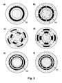
- Material cuts introduced, which in the cylindrical assembly of the segments give a mixed structure according to the invention ( FIG. 6 ).
- the use of at least two differently structured cylinder segment types is required, which are used in the assembly in each case alternating arrangement.
- a mixer according to the invention Due to the repeated division and redeployment of the - possibly stratified on the input side - process fluid flow along the mixing section can be easily realized on a number of mixing stages (eg 5 to 20) to the mixer output theoretical thicknesses of the individual fluid layers in the range less than 0.01 mm or even less will be realized.
- a mixer according to the invention thus achieves in many cases approximately the performance of a multi-lamination micromixer with comparable pressure drop and flow values.
- the static mixer according to the invention has by well a factor of 5 to 20 larger minimum dimensions of the channels through which it flows and is therefore considerably less susceptible to deposits and blockages.
- a static mixer according to the invention u.a.
- a static mixer according to the invention can be used particularly advantageously for producing polymers or polymer mixtures, for mixing at least two fluid media, of which at least one is a suspension, or for producing suspensions by precipitation.
- FIG. 1a shows the longitudinal section of a static mixer according to the invention in an embodiment, as it is preferably used for mixing two different fluid media.
- the mixing section (2) consisting of a sequence of sequentially flowed through mixing stages (1), in this case a mixer head (3) is connected upstream, which the two via the inlets (5a / b) separately supplied to be mixed media (7a / b) in the form of a radially stratified ring stream fed into the mixing section.
- the mixture (8) leaves the mixer via the outlet segment (4) attached to the outlet (6) of the mixing section.
- FIG. 1b shows the longitudinal section of a static mixer according to the invention in a further embodiment, which can preferably be used for the further mixing or homogenization of an already premixed product stream (7).
- This design is different from the one in Fig. 1 shown substantially by the shape of the mixer head, which is provided in this case only with a fluid inlet (5).
- Figure 1c shows the longitudinal section of a static mixer according to the invention in a third embodiment, which preferably serves to mix three separate fluid streams.
- This may be, for example, three different media that are to be processed simultaneously to a uniform mixture.
- FIG. 2 1 illustrates the fluid guidance within a mixing stage of a mixer according to the invention on the basis of a sequence of successive cross sections in the direction of flow: the mixture flow enters the mixing stage in the form of a ring flow (10), which in the ideal case is radially stratified Fig. 2a ). In the next step, this ring flow merges into a (even) number of subchannels (11), ie it is segmented azimuthally ( Fig. 2b ). In the further course, the sub-channels experience an alternately opposite radial offset ( Fig. 2b after 2c), until adjacent sub-channels in the radial direction no longer overlap with each other.
- a ring flow 10
- this ring flow merges into a (even) number of subchannels (11), ie it is segmented azimuthally ( Fig. 2b ).
- the sub-channels experience an alternately opposite radial offset ( Fig. 2b after 2c), until adjacent sub-channels in the
- the sub-channels undergo an azimuthal extension until originally adjacent sub-channels largely overlap again in the azimuthal direction ( Fig. 2c after 2d).
- an unsegmented ring flow can be achieved ( Fig. 2e ) or the subsegmentation after the azimuthal stretching ( Fig. 2d ) preferably goes directly into the subchannel arrangement of the following mixing stage ( Fig. 2f - then rotated by 1/16 turn) over.
- the azimuthal extension of the sub-channels which represents the transition of the radially offset sub-channels into a (possibly segmented) ring flow ( Fig.
- FIG. 3 an alternative fluid guide is shown within a mixing stage of a mixer according to the invention with reference to a sequence of successive cross-sections in the flow direction.
- an azimuthal segmentation of the incoming ring current and an alternating radial offset of the resulting sub-channels takes place ( Fig. 3a and b ).
- adjacent sub-channels are offset in opposite azimuthal direction so that they overlap at least approximately completely azimuthally ( Fig. 2c ).
- the sub-channels are stretched so far in the azimuthal direction that at the end of the mixing stage a (possibly segmented) ring flow is again achieved ( Fig. 2d to f ).
- FIG. 4 illustrates substantially the same fluid management within a mixing stage of a mixer according to the invention, but also provides the sequence of sub-channel courses in the subsequent mixing stage ( Fig. 4f to i
- the azimuthal offset of radially displaced adjacent subchannels takes place in the opposite direction to the previous mixing stage.
- This form of fluid guidance in which the direction of the azimuthal offset alternates within successive mixing stages, is particularly preferred since this results in particularly good cross-mixing between the sub-channels along the mixing path.
- FIG. 5 shows a possible embodiment of the mixing section (detail) of a mixer according to the invention.
- This consists of a cylindrical, provided on its outer surface with channel structures core (20) and alternately pushed over inner (21) and outer (22) ring segments together, which results in the combination of the desired realization of the sub-channel guide (in the example shown in Fig. 2 sketched).
- FIG. 6 shows a perspective view of another possible embodiment of the mixing section of a mixer according to the invention (detail). This is composed of two different types of wedge-shaped cylinder segments, in whose side surfaces specific channel structure elements are introduced. In an alternating arrangement of the cylinder segments to a complete cylinder, the channel structure elements of the individual segments connect to the mixing structure of a mixing section according to the invention.
- FIG. 7 is a further possible embodiment of a mixing stage of the mixing section of a mixer according to the invention shown.
- the sub-channels are partially incorporated as a continuous openings or holes in different, preferably round, discs.
- the openings or bores form a coherent system of channels of a mixing section according to the invention.
- the disk stack is inserted for use in a suitable, eg tubular housing (not shown here), which optionally contains a mixer head and an outlet segment for supply and discharge of the process fluids.
Landscapes
- Chemical & Material Sciences (AREA)
- Dispersion Chemistry (AREA)
- Chemical Kinetics & Catalysis (AREA)
- Engineering & Computer Science (AREA)
- Mechanical Engineering (AREA)
- Processing And Handling Of Plastics And Other Materials For Molding In General (AREA)
Applications Claiming Priority (2)
| Application Number | Priority Date | Filing Date | Title |
|---|---|---|---|
| DE102009011996 | 2009-03-06 | ||
| PCT/EP2010/001104 WO2010099884A1 (de) | 2009-03-06 | 2010-02-23 | Koaxialer kompaktstatikmischer sowie dessen verwendung |
Publications (2)
| Publication Number | Publication Date |
|---|---|
| EP2403633A1 EP2403633A1 (de) | 2012-01-11 |
| EP2403633B1 true EP2403633B1 (de) | 2013-04-17 |
Family
ID=42227574
Family Applications (1)
| Application Number | Title | Priority Date | Filing Date |
|---|---|---|---|
| EP10706933.8A Active EP2403633B1 (de) | 2009-03-06 | 2010-02-23 | Koaxialer kompaktstatikmischer sowie dessen verwendung |
Country Status (5)
| Country | Link |
|---|---|
| US (1) | US8696193B2 (enExample) |
| EP (1) | EP2403633B1 (enExample) |
| JP (1) | JP2012519577A (enExample) |
| CN (1) | CN102355942B (enExample) |
| WO (1) | WO2010099884A1 (enExample) |
Cited By (1)
| Publication number | Priority date | Publication date | Assignee | Title |
|---|---|---|---|---|
| US11440033B2 (en) | 2017-12-29 | 2022-09-13 | Medmix Switzerland Ag | Mixer, multi-component dispenser, and method of dispensing multi-component material from a multi-component dispenser |
Families Citing this family (45)
| Publication number | Priority date | Publication date | Assignee | Title |
|---|---|---|---|---|
| US8967852B2 (en) * | 2010-09-17 | 2015-03-03 | Delavan Inc | Mixers for immiscible fluids |
| CN103338847B (zh) * | 2011-01-12 | 2016-08-10 | 利乐拉瓦尔集团及财务有限公司 | 用于高粘度流体的层倍增器 |
| JP6068926B2 (ja) * | 2012-10-23 | 2017-01-25 | 矢崎総業株式会社 | 射出成形用ノズル |
| AU2014203909A1 (en) * | 2013-01-07 | 2015-08-06 | 1,4 Group, Inc. | Thermal fogger for creating stable aerosols |
| US9693958B2 (en) * | 2013-03-15 | 2017-07-04 | Cureport, Inc. | Methods and devices for preparation of lipid nanoparticles |
| KR102098771B1 (ko) * | 2013-08-14 | 2020-04-08 | 재단법인 포항산업과학연구원 | 마이크로 버블형 스크러버를 이용한 NOx 가스를 질산으로 회수하는 방법 |
| DE102013020469A1 (de) * | 2013-12-06 | 2015-06-11 | Webasto SE | Wärmeübertrager und Verfahren zum Herstellen eines Wärmeübertragers |
| FR3015315B1 (fr) * | 2013-12-19 | 2016-02-12 | Bostik Sa | Procede d'application a chaud d'une composition adhesive silylee |
| RU2553861C1 (ru) * | 2014-03-12 | 2015-06-20 | Федеральное государственное бюджетное образовательное учреждение высшего профессионального образования "Тамбовский государственный технический университет" ФГБОУ ВПО ТГТУ | Гидродинамический смеситель |
| JP6128397B2 (ja) * | 2014-08-27 | 2017-05-17 | 有限会社 開商 | ガス混合装置 |
| US9470132B2 (en) | 2014-12-05 | 2016-10-18 | Cummins Emission Solutions, Inc. | Compact radial exterior exhaust assisted decomposition reactor pipe |
| US20160265779A1 (en) * | 2015-03-11 | 2016-09-15 | General Electric Company | Twin radial splitter-chevron mixer with converging throat |
| CN104786382B (zh) * | 2015-04-24 | 2017-01-04 | 浙江省现代纺织工业研究院 | 一种双锥面动态混合器 |
| KR20160147482A (ko) * | 2015-06-15 | 2016-12-23 | 삼성전자주식회사 | 가스 혼합부를 갖는 반도체 소자 제조 설비 |
| US9732775B2 (en) * | 2015-06-24 | 2017-08-15 | The Boeing Company | Flow straightener apparatus and systems for ducted air |
| RU2611878C1 (ru) * | 2015-11-05 | 2017-03-01 | Федеральное государственное бюджетное образовательное учреждение высшего образования "Красноярский государственный аграрный университет" | Вихревой гидродинамический смеситель |
| WO2017083737A1 (en) | 2015-11-13 | 2017-05-18 | Re Mixers, Inc. | Static mixer |
| CN105666720B (zh) * | 2016-04-15 | 2017-12-22 | 河南省龙都生物科技有限公司 | 聚乳酸预聚混料装置 |
| RU2618078C1 (ru) * | 2016-04-25 | 2017-05-02 | Федеральное государственное бюджетное образовательное учреждение высшего образования "Тамбовский государственный технический университет" ФГБОУ ВО "ТГТУ" | Гидродинамический смеситель |
| RU2618865C1 (ru) * | 2016-05-04 | 2017-05-11 | Федеральное государственное бюджетное образовательное учреждение высшего образования "Тамбовский государственный технический университет" ФГБОУ ВО "ТГТУ" | Гидродинамический смеситель |
| RU169527U1 (ru) * | 2016-10-04 | 2017-03-22 | Виль Файзулович Галиакбаров | Струйный гидравлический смеситель |
| RU171985U1 (ru) * | 2016-11-15 | 2017-06-23 | Эмилия Вильевна Галиакбарова | Поточный струйный смеситель |
| RU2625874C1 (ru) * | 2016-11-15 | 2017-07-19 | Федеральное государственное бюджетное образовательное учреждение высшего образования "Тамбовский государственный технический университет" (ФГБОУ ВО "ТГТУ") | Гидродинамический смеситель |
| CN106582340B (zh) * | 2017-01-13 | 2022-07-12 | 理星(天津)生物科技有限公司 | 一种高压均质机 |
| US11185830B2 (en) | 2017-09-06 | 2021-11-30 | Waters Technologies Corporation | Fluid mixer |
| JP2019084763A (ja) * | 2017-11-07 | 2019-06-06 | 株式会社神戸製鋼所 | 混合装置 |
| JP6831317B2 (ja) * | 2017-11-07 | 2021-02-17 | 株式会社神戸製鋼所 | 混合装置 |
| RU180014U1 (ru) * | 2018-02-21 | 2018-05-30 | Федеральное государственное бюджетное образовательное учреждение высшего образования "Уфимский государственный нефтяной технический университет" | Струйный смеситель |
| RU188163U1 (ru) * | 2018-12-13 | 2019-04-01 | Федеральное государственное бюджетное образовательное учреждение высшего образования "МИРЭА - Российский технологический университет" | Устройство для смешивания компонентов во встречных потоках |
| JP7371835B2 (ja) * | 2019-02-19 | 2023-10-31 | 株式会社セイワマシン | スラリー流動化装置 |
| CN110280158A (zh) * | 2019-08-08 | 2019-09-27 | 中国联合网络通信集团有限公司 | 一种分流罩及静态混合器 |
| CN119715878A (zh) | 2019-08-12 | 2025-03-28 | 沃特世科技公司 | 用于色谱系统的混合器 |
| WO2021081122A1 (en) | 2019-10-21 | 2021-04-29 | Re Mixers, Inc | Static mixer |
| RU196319U1 (ru) * | 2019-12-12 | 2020-02-25 | федеральное государственное бюджетное образовательное учреждение высшего образования "МИРЭА-Российский технологический университет" | Устройство для смешивания компонентов во встречных потоках |
| US20230172252A1 (en) * | 2020-04-10 | 2023-06-08 | Emulco Laboratories C.V.B.A. | Method for producing emulsions |
| CN111330471B (zh) * | 2020-04-17 | 2025-01-17 | 重庆鑫乡科技有限公司 | 一种静态混合单元及静态混合器 |
| EP4179310B1 (en) | 2020-07-07 | 2025-07-30 | Waters Technologies Corporation | Mixer for liquid chromatography |
| EP4179311B1 (en) | 2020-07-07 | 2025-07-30 | Waters Technologies Corporation | Combination mixer arrangement for noise reduction in fluid chromatography |
| EP3970842A1 (en) * | 2020-09-17 | 2022-03-23 | Sulzer Mixpac AG | Mixing segment for a static mixer and static mixer |
| CN116194767A (zh) | 2020-09-22 | 2023-05-30 | 沃特世科技公司 | 连续流混合器 |
| WO2022245566A1 (en) | 2021-05-20 | 2022-11-24 | Waters Technologies Corporation | Equal dispersion split-flow mixer |
| EP4359118A1 (en) | 2021-06-23 | 2024-05-01 | Waters Technologies Corporation | Passive solvent mixer for liquid chromatography |
| CN114225881B (zh) * | 2021-12-14 | 2023-11-10 | 河南汇金智能装备有限公司 | 管道内气流反应釜以及使用气流反应釜的脱硫装置 |
| CN115253984B (zh) * | 2022-08-31 | 2023-05-30 | 池州飞昊达化工有限公司 | 一种用于制备乙氧氟草醚除草剂的管式反应器及其使用方法 |
| CN119394579B (zh) * | 2024-10-23 | 2025-09-30 | 北京东方计量测试研究所 | 风洞piv示踪粒子快速均匀冷却混合装置 |
Family Cites Families (25)
| Publication number | Priority date | Publication date | Assignee | Title |
|---|---|---|---|---|
| US900656A (en) * | 1908-03-07 | 1908-10-06 | Lillian Von Gessner | Method of protecting iron. |
| US1637697A (en) * | 1927-03-07 | 1927-08-02 | Duriron Co | Mixing nozzle |
| US2531547A (en) | 1946-09-09 | 1950-11-28 | Phillips Petroleum Co | Apparatus for washing oils with an immiscible wash liquid |
| US3051452A (en) | 1957-11-29 | 1962-08-28 | American Enka Corp | Process and apparatus for mixing |
| CH373356A (de) | 1957-11-29 | 1963-11-30 | Onderzoekings Inst Res | Verfahren und Vorrichtung zum Mischen strömender, gasförmiger, flüssiger und/oder körniger Medien mittels ortsfester Leitelemente |
| GB941893A (en) | 1960-05-31 | 1963-11-13 | Dow Chemical Co | Method for mixing fluid streams |
| US3923288A (en) * | 1973-12-27 | 1975-12-02 | Komax Systems Inc | Material mixing apparatus |
| US4198168A (en) * | 1978-04-12 | 1980-04-15 | Liquid Control Incorporated | Phase blending static mixing process and apparatus |
| JPS55109642A (en) * | 1979-02-19 | 1980-08-23 | Japan Steel Works Ltd:The | Thermoplastic resin extruder |
| DE3372337D1 (en) * | 1982-12-06 | 1987-08-13 | Windmoeller & Hoelscher | Method and device for the formation and rearranging of partial streams from extruded thermoplastic and/or elastomeric materials |
| US4848920A (en) * | 1988-02-26 | 1989-07-18 | Husky Injection Molding Systems Ltd. | Static mixer |
| DE59309890D1 (de) | 1993-10-05 | 2000-01-05 | Sulzer Chemtech Ag Winterthur | Vorrichtung zum Homogenisieren von hochviskosen Fluiden |
| US5454640A (en) * | 1994-01-28 | 1995-10-03 | Welker; Robert H. | Flow diffuser for redistributing stratified liquids in a pipeline |
| DE19511603A1 (de) | 1995-03-30 | 1996-10-02 | Norbert Dr Ing Schwesinger | Vorrichtung zum Mischen kleiner Flüssigkeitsmengen |
| DE19536858C2 (de) | 1995-10-03 | 2000-04-13 | Danfoss As | Verfahren und Vorrichtung zum Transport eines Fluids durch einen Kanal |
| DE19634450A1 (de) * | 1996-08-26 | 1998-03-05 | Basf Ag | Vorrichtung zur kontinuierlichen Durchführung chemischer Reaktionen |
| DE19746583A1 (de) | 1997-10-22 | 1999-04-29 | Merck Patent Gmbh | Mikromischer |
| DE19927554C2 (de) | 1999-06-16 | 2002-12-19 | Inst Mikrotechnik Mainz Gmbh | Mikromischer |
| DE19933441A1 (de) | 1999-07-16 | 2001-01-18 | Bayer Ag | Verstellbarer Strahldispergator zur Herstellung wäßriger 2-Komponenten-Polyurethanlack-Emulsionen |
| US7077561B2 (en) | 2002-07-15 | 2006-07-18 | Sulzer Chemtech Ag | Assembly of crossing elements and method of constructing same |
| DE20218972U1 (de) | 2002-12-07 | 2003-02-13 | Ehrfeld Mikrotechnik AG, 55234 Wendelsheim | Statischer Laminationsmikrovermischer |
| JP4432104B2 (ja) * | 2003-05-30 | 2010-03-17 | 富士フイルム株式会社 | マイクロリアクター |
| DE10326381B4 (de) | 2003-06-12 | 2005-09-22 | Jähn, Peter | Turbulenzerzeuger |
| EP1510247B1 (de) * | 2003-08-26 | 2008-04-30 | Sulzer Chemtech AG | Statischer Mischer mit polymorpher Struktur |
| DE102004007727A1 (de) | 2004-02-16 | 2005-09-01 | Margret Spiegel | Herkömmliche Karbonatorsysteme oder Imprägniersysteme zusätzlich mindestens ein Hohlkörper-Inlineimprägnierer befüllt mit Schüttgut um schon karbonisierte oder imprägnierte Flüssigkeiten nachzukarbonisieren oder imprägnieren |
-
2010
- 2010-02-23 JP JP2011552344A patent/JP2012519577A/ja active Pending
- 2010-02-23 WO PCT/EP2010/001104 patent/WO2010099884A1/de not_active Ceased
- 2010-02-23 CN CN201080010750.7A patent/CN102355942B/zh active Active
- 2010-02-23 US US13/201,349 patent/US8696193B2/en active Active
- 2010-02-23 EP EP10706933.8A patent/EP2403633B1/de active Active
Cited By (1)
| Publication number | Priority date | Publication date | Assignee | Title |
|---|---|---|---|---|
| US11440033B2 (en) | 2017-12-29 | 2022-09-13 | Medmix Switzerland Ag | Mixer, multi-component dispenser, and method of dispensing multi-component material from a multi-component dispenser |
Also Published As
| Publication number | Publication date |
|---|---|
| JP2012519577A (ja) | 2012-08-30 |
| CN102355942B (zh) | 2014-09-24 |
| CN102355942A (zh) | 2012-02-15 |
| EP2403633A1 (de) | 2012-01-11 |
| WO2010099884A1 (de) | 2010-09-10 |
| US8696193B2 (en) | 2014-04-15 |
| US20120033524A1 (en) | 2012-02-09 |
Similar Documents
| Publication | Publication Date | Title |
|---|---|---|
| EP2403633B1 (de) | Koaxialer kompaktstatikmischer sowie dessen verwendung | |
| DE19703779C2 (de) | Verfahren und Vorrichtung zur Herstellung eines dispersen Gemisches | |
| EP1648581B1 (de) | Extraktionsverfahren unter verwendung eines statischen mikromischers | |
| EP1658129B1 (de) | Statischer mikromischer | |
| EP1242171B1 (de) | Mikrovermischer | |
| EP1390131B1 (de) | Verfahren und statischer mikrovermischer zum mischen mindestens zweier fluide | |
| DE69716224T2 (de) | Vorrichtungen zur Herstellung von Feinpartikeln | |
| WO2002016017A9 (de) | Verfahren und statischer mikrovermischer zum mischen mindestens zweier fluide | |
| EP2550088B1 (de) | Misch- oder dispergierelement und verfahren zum statischen mischen oder dispergieren | |
| EP2184103A1 (de) | Modularer Reaktor | |
| EP2608875B1 (de) | Vorrichtung und verfahren zur gasdispergierung | |
| EP2915581B1 (de) | Statischer Mischer | |
| EP1278593B1 (de) | Statisches mischelement | |
| WO2002089965A1 (de) | Verfahren und statischer mischer zum mischen mindestens zweier fluide | |
| EP2090353B1 (de) | Reaktionsmischersystem zur Vermischung und chemischer Reaktion von mindestens zwei Fluiden | |
| EP2680957B1 (de) | Verfahren und vorrichtung zur vermischung zweier fluidströme | |
| CH705823A2 (de) | Mit einem Wärmetauscher versehener Kreislaufreaktor. | |
| EP2129454B1 (de) | Strahldispergator | |
| EP0602369B1 (de) | Reaktorkonstruktionen für die Methylformiatsynthese | |
| DE10159985B4 (de) | Mikroemulgator | |
| DE102005060280B4 (de) | Integrierbarer Mikromischer sowie dessen Verwendung | |
| DE202006001952U1 (de) | Vorrichtung zum Herstellen von Dispersionen | |
| WO2015028540A1 (de) | Vorrichtung und verfahren zum herstellen von acetylen und synthesegas | |
| EP1776183A1 (de) | Vorrichtung und verfahren zur kontinuierlichen durchführung chemischer prozesse | |
| EP3189887A1 (de) | Kavitationsreaktor zum behandeln von fliessfähigen substanzen |
Legal Events
| Date | Code | Title | Description |
|---|---|---|---|
| PUAI | Public reference made under article 153(3) epc to a published international application that has entered the european phase |
Free format text: ORIGINAL CODE: 0009012 |
|
| 17P | Request for examination filed |
Effective date: 20111006 |
|
| AK | Designated contracting states |
Kind code of ref document: A1 Designated state(s): AT BE BG CH CY CZ DE DK EE ES FI FR GB GR HR HU IE IS IT LI LT LU LV MC MK MT NL NO PL PT RO SE SI SK SM TR |
|
| DAX | Request for extension of the european patent (deleted) | ||
| GRAP | Despatch of communication of intention to grant a patent |
Free format text: ORIGINAL CODE: EPIDOSNIGR1 |
|
| GRAS | Grant fee paid |
Free format text: ORIGINAL CODE: EPIDOSNIGR3 |
|
| GRAA | (expected) grant |
Free format text: ORIGINAL CODE: 0009210 |
|
| AK | Designated contracting states |
Kind code of ref document: B1 Designated state(s): AT BE BG CH CY CZ DE DK EE ES FI FR GB GR HR HU IE IS IT LI LT LU LV MC MK MT NL NO PL PT RO SE SI SK SM TR |
|
| REG | Reference to a national code |
Ref country code: GB Ref legal event code: FG4D Free format text: NOT ENGLISH |
|
| REG | Reference to a national code |
Ref country code: CH Ref legal event code: EP |
|
| REG | Reference to a national code |
Ref country code: IE Ref legal event code: FG4D Free format text: LANGUAGE OF EP DOCUMENT: GERMAN |
|
| REG | Reference to a national code |
Ref country code: AT Ref legal event code: REF Ref document number: 606895 Country of ref document: AT Kind code of ref document: T Effective date: 20130515 |
|
| REG | Reference to a national code |
Ref country code: DE Ref legal event code: R096 Ref document number: 502010002992 Country of ref document: DE Effective date: 20130613 |
|
| REG | Reference to a national code |
Ref country code: NL Ref legal event code: T3 |
|
| REG | Reference to a national code |
Ref country code: LT Ref legal event code: MG4D |
|
| PG25 | Lapsed in a contracting state [announced via postgrant information from national office to epo] |
Ref country code: FI Free format text: LAPSE BECAUSE OF FAILURE TO SUBMIT A TRANSLATION OF THE DESCRIPTION OR TO PAY THE FEE WITHIN THE PRESCRIBED TIME-LIMIT Effective date: 20130417 Ref country code: SI Free format text: LAPSE BECAUSE OF FAILURE TO SUBMIT A TRANSLATION OF THE DESCRIPTION OR TO PAY THE FEE WITHIN THE PRESCRIBED TIME-LIMIT Effective date: 20130417 Ref country code: PT Free format text: LAPSE BECAUSE OF FAILURE TO SUBMIT A TRANSLATION OF THE DESCRIPTION OR TO PAY THE FEE WITHIN THE PRESCRIBED TIME-LIMIT Effective date: 20130819 Ref country code: SE Free format text: LAPSE BECAUSE OF FAILURE TO SUBMIT A TRANSLATION OF THE DESCRIPTION OR TO PAY THE FEE WITHIN THE PRESCRIBED TIME-LIMIT Effective date: 20130417 Ref country code: LT Free format text: LAPSE BECAUSE OF FAILURE TO SUBMIT A TRANSLATION OF THE DESCRIPTION OR TO PAY THE FEE WITHIN THE PRESCRIBED TIME-LIMIT Effective date: 20130417 Ref country code: ES Free format text: LAPSE BECAUSE OF FAILURE TO SUBMIT A TRANSLATION OF THE DESCRIPTION OR TO PAY THE FEE WITHIN THE PRESCRIBED TIME-LIMIT Effective date: 20130728 Ref country code: IS Free format text: LAPSE BECAUSE OF FAILURE TO SUBMIT A TRANSLATION OF THE DESCRIPTION OR TO PAY THE FEE WITHIN THE PRESCRIBED TIME-LIMIT Effective date: 20130817 Ref country code: GR Free format text: LAPSE BECAUSE OF FAILURE TO SUBMIT A TRANSLATION OF THE DESCRIPTION OR TO PAY THE FEE WITHIN THE PRESCRIBED TIME-LIMIT Effective date: 20130718 Ref country code: NO Free format text: LAPSE BECAUSE OF FAILURE TO SUBMIT A TRANSLATION OF THE DESCRIPTION OR TO PAY THE FEE WITHIN THE PRESCRIBED TIME-LIMIT Effective date: 20130717 |
|
| PG25 | Lapsed in a contracting state [announced via postgrant information from national office to epo] |
Ref country code: CY Free format text: LAPSE BECAUSE OF FAILURE TO SUBMIT A TRANSLATION OF THE DESCRIPTION OR TO PAY THE FEE WITHIN THE PRESCRIBED TIME-LIMIT Effective date: 20130417 Ref country code: LV Free format text: LAPSE BECAUSE OF FAILURE TO SUBMIT A TRANSLATION OF THE DESCRIPTION OR TO PAY THE FEE WITHIN THE PRESCRIBED TIME-LIMIT Effective date: 20130417 Ref country code: HR Free format text: LAPSE BECAUSE OF FAILURE TO SUBMIT A TRANSLATION OF THE DESCRIPTION OR TO PAY THE FEE WITHIN THE PRESCRIBED TIME-LIMIT Effective date: 20130417 Ref country code: PL Free format text: LAPSE BECAUSE OF FAILURE TO SUBMIT A TRANSLATION OF THE DESCRIPTION OR TO PAY THE FEE WITHIN THE PRESCRIBED TIME-LIMIT Effective date: 20130417 Ref country code: BG Free format text: LAPSE BECAUSE OF FAILURE TO SUBMIT A TRANSLATION OF THE DESCRIPTION OR TO PAY THE FEE WITHIN THE PRESCRIBED TIME-LIMIT Effective date: 20130717 |
|
| PG25 | Lapsed in a contracting state [announced via postgrant information from national office to epo] |
Ref country code: CZ Free format text: LAPSE BECAUSE OF FAILURE TO SUBMIT A TRANSLATION OF THE DESCRIPTION OR TO PAY THE FEE WITHIN THE PRESCRIBED TIME-LIMIT Effective date: 20130417 Ref country code: EE Free format text: LAPSE BECAUSE OF FAILURE TO SUBMIT A TRANSLATION OF THE DESCRIPTION OR TO PAY THE FEE WITHIN THE PRESCRIBED TIME-LIMIT Effective date: 20130417 Ref country code: DK Free format text: LAPSE BECAUSE OF FAILURE TO SUBMIT A TRANSLATION OF THE DESCRIPTION OR TO PAY THE FEE WITHIN THE PRESCRIBED TIME-LIMIT Effective date: 20130417 Ref country code: SK Free format text: LAPSE BECAUSE OF FAILURE TO SUBMIT A TRANSLATION OF THE DESCRIPTION OR TO PAY THE FEE WITHIN THE PRESCRIBED TIME-LIMIT Effective date: 20130417 |
|
| PLBE | No opposition filed within time limit |
Free format text: ORIGINAL CODE: 0009261 |
|
| STAA | Information on the status of an ep patent application or granted ep patent |
Free format text: STATUS: NO OPPOSITION FILED WITHIN TIME LIMIT |
|
| PG25 | Lapsed in a contracting state [announced via postgrant information from national office to epo] |
Ref country code: RO Free format text: LAPSE BECAUSE OF FAILURE TO SUBMIT A TRANSLATION OF THE DESCRIPTION OR TO PAY THE FEE WITHIN THE PRESCRIBED TIME-LIMIT Effective date: 20130417 Ref country code: IT Free format text: LAPSE BECAUSE OF FAILURE TO SUBMIT A TRANSLATION OF THE DESCRIPTION OR TO PAY THE FEE WITHIN THE PRESCRIBED TIME-LIMIT Effective date: 20130417 |
|
| 26N | No opposition filed |
Effective date: 20140120 |
|
| REG | Reference to a national code |
Ref country code: DE Ref legal event code: R097 Ref document number: 502010002992 Country of ref document: DE Effective date: 20140120 |
|
| PG25 | Lapsed in a contracting state [announced via postgrant information from national office to epo] |
Ref country code: MC Free format text: LAPSE BECAUSE OF FAILURE TO SUBMIT A TRANSLATION OF THE DESCRIPTION OR TO PAY THE FEE WITHIN THE PRESCRIBED TIME-LIMIT Effective date: 20130417 Ref country code: LU Free format text: LAPSE BECAUSE OF FAILURE TO SUBMIT A TRANSLATION OF THE DESCRIPTION OR TO PAY THE FEE WITHIN THE PRESCRIBED TIME-LIMIT Effective date: 20140223 |
|
| GBPC | Gb: european patent ceased through non-payment of renewal fee |
Effective date: 20140223 |
|
| REG | Reference to a national code |
Ref country code: IE Ref legal event code: MM4A |
|
| PG25 | Lapsed in a contracting state [announced via postgrant information from national office to epo] |
Ref country code: IE Free format text: LAPSE BECAUSE OF NON-PAYMENT OF DUE FEES Effective date: 20140223 Ref country code: GB Free format text: LAPSE BECAUSE OF NON-PAYMENT OF DUE FEES Effective date: 20140223 |
|
| REG | Reference to a national code |
Ref country code: FR Ref legal event code: PLFP Year of fee payment: 7 |
|
| PG25 | Lapsed in a contracting state [announced via postgrant information from national office to epo] |
Ref country code: MT Free format text: LAPSE BECAUSE OF FAILURE TO SUBMIT A TRANSLATION OF THE DESCRIPTION OR TO PAY THE FEE WITHIN THE PRESCRIBED TIME-LIMIT Effective date: 20130417 |
|
| PG25 | Lapsed in a contracting state [announced via postgrant information from national office to epo] |
Ref country code: SM Free format text: LAPSE BECAUSE OF FAILURE TO SUBMIT A TRANSLATION OF THE DESCRIPTION OR TO PAY THE FEE WITHIN THE PRESCRIBED TIME-LIMIT Effective date: 20130417 |
|
| PG25 | Lapsed in a contracting state [announced via postgrant information from national office to epo] |
Ref country code: HU Free format text: LAPSE BECAUSE OF FAILURE TO SUBMIT A TRANSLATION OF THE DESCRIPTION OR TO PAY THE FEE WITHIN THE PRESCRIBED TIME-LIMIT; INVALID AB INITIO Effective date: 20100223 Ref country code: TR Free format text: LAPSE BECAUSE OF FAILURE TO SUBMIT A TRANSLATION OF THE DESCRIPTION OR TO PAY THE FEE WITHIN THE PRESCRIBED TIME-LIMIT Effective date: 20130417 |
|
| REG | Reference to a national code |
Ref country code: FR Ref legal event code: PLFP Year of fee payment: 8 |
|
| REG | Reference to a national code |
Ref country code: FR Ref legal event code: PLFP Year of fee payment: 9 |
|
| PG25 | Lapsed in a contracting state [announced via postgrant information from national office to epo] |
Ref country code: MK Free format text: LAPSE BECAUSE OF FAILURE TO SUBMIT A TRANSLATION OF THE DESCRIPTION OR TO PAY THE FEE WITHIN THE PRESCRIBED TIME-LIMIT Effective date: 20130417 |
|
| REG | Reference to a national code |
Ref country code: DE Ref legal event code: R079 Ref document number: 502010002992 Country of ref document: DE Free format text: PREVIOUS MAIN CLASS: B01F0005060000 Ipc: B01F0025400000 |
|
| P01 | Opt-out of the competence of the unified patent court (upc) registered |
Effective date: 20230517 |
|
| PGFP | Annual fee paid to national office [announced via postgrant information from national office to epo] |
Ref country code: DE Payment date: 20250219 Year of fee payment: 16 |
|
| PGFP | Annual fee paid to national office [announced via postgrant information from national office to epo] |
Ref country code: AT Payment date: 20250220 Year of fee payment: 16 Ref country code: BE Payment date: 20250219 Year of fee payment: 16 Ref country code: CH Payment date: 20250301 Year of fee payment: 16 |
|
| PGFP | Annual fee paid to national office [announced via postgrant information from national office to epo] |
Ref country code: FR Payment date: 20250219 Year of fee payment: 16 |
|
| REG | Reference to a national code |
Ref country code: CH Ref legal event code: U11 Free format text: ST27 STATUS EVENT CODE: U-0-0-U10-U11 (AS PROVIDED BY THE NATIONAL OFFICE) Effective date: 20260301 |
|
| PGFP | Annual fee paid to national office [announced via postgrant information from national office to epo] |
Ref country code: NL Payment date: 20260225 Year of fee payment: 17 |