EP2403633B1 - Coaxial compact static mixer and use thereof - Google Patents
Coaxial compact static mixer and use thereof Download PDFInfo
- Publication number
- EP2403633B1 EP2403633B1 EP10706933.8A EP10706933A EP2403633B1 EP 2403633 B1 EP2403633 B1 EP 2403633B1 EP 10706933 A EP10706933 A EP 10706933A EP 2403633 B1 EP2403633 B1 EP 2403633B1
- Authority
- EP
- European Patent Office
- Prior art keywords
- mixing
- static mixer
- channels
- mixer according
- annular
- Prior art date
- Legal status (The legal status is an assumption and is not a legal conclusion. Google has not performed a legal analysis and makes no representation as to the accuracy of the status listed.)
- Active
Links
- 230000003068 static effect Effects 0.000 title claims description 41
- 238000002156 mixing Methods 0.000 claims description 157
- 230000036961 partial effect Effects 0.000 claims description 16
- 238000006073 displacement reaction Methods 0.000 claims description 6
- 239000000725 suspension Substances 0.000 claims description 6
- 239000000463 material Substances 0.000 claims description 5
- 230000011218 segmentation Effects 0.000 claims description 3
- 230000004927 fusion Effects 0.000 claims description 2
- 229920000642 polymer Polymers 0.000 claims description 2
- 229920002959 polymer blend Polymers 0.000 claims description 2
- 238000001556 precipitation Methods 0.000 claims description 2
- 230000009466 transformation Effects 0.000 claims 1
- 239000000203 mixture Substances 0.000 description 43
- 239000012530 fluid Substances 0.000 description 27
- 238000000034 method Methods 0.000 description 16
- 230000008569 process Effects 0.000 description 14
- 239000000126 substance Substances 0.000 description 8
- 238000006243 chemical reaction Methods 0.000 description 6
- 230000001965 increasing effect Effects 0.000 description 6
- 230000007704 transition Effects 0.000 description 6
- 230000008901 benefit Effects 0.000 description 4
- 230000015572 biosynthetic process Effects 0.000 description 4
- 239000007788 liquid Substances 0.000 description 4
- 238000004519 manufacturing process Methods 0.000 description 4
- 238000011144 upstream manufacturing Methods 0.000 description 4
- 238000010438 heat treatment Methods 0.000 description 3
- 238000007726 management method Methods 0.000 description 3
- 230000002829 reductive effect Effects 0.000 description 3
- 238000005496 tempering Methods 0.000 description 3
- PXHVJJICTQNCMI-UHFFFAOYSA-N Nickel Chemical compound [Ni] PXHVJJICTQNCMI-UHFFFAOYSA-N 0.000 description 2
- MCMNRKCIXSYSNV-UHFFFAOYSA-N Zirconium dioxide Chemical compound O=[Zr]=O MCMNRKCIXSYSNV-UHFFFAOYSA-N 0.000 description 2
- 229910045601 alloy Inorganic materials 0.000 description 2
- 239000000956 alloy Substances 0.000 description 2
- 238000010276 construction Methods 0.000 description 2
- 230000003247 decreasing effect Effects 0.000 description 2
- 238000009826 distribution Methods 0.000 description 2
- 239000000839 emulsion Substances 0.000 description 2
- -1 etc.) Polymers 0.000 description 2
- 238000000265 homogenisation Methods 0.000 description 2
- 230000001939 inductive effect Effects 0.000 description 2
- 229910052751 metal Inorganic materials 0.000 description 2
- 239000002184 metal Substances 0.000 description 2
- 238000010327 methods by industry Methods 0.000 description 2
- 238000005192 partition Methods 0.000 description 2
- 239000000047 product Substances 0.000 description 2
- 239000007787 solid Substances 0.000 description 2
- FIKFLLIUPUVONI-UHFFFAOYSA-N 8-(2-phenylethyl)-1-oxa-3,8-diazaspiro[4.5]decan-2-one;hydrochloride Chemical compound Cl.O1C(=O)NCC11CCN(CCC=2C=CC=CC=2)CC1 FIKFLLIUPUVONI-UHFFFAOYSA-N 0.000 description 1
- 229910001369 Brass Inorganic materials 0.000 description 1
- RYGMFSIKBFXOCR-UHFFFAOYSA-N Copper Chemical compound [Cu] RYGMFSIKBFXOCR-UHFFFAOYSA-N 0.000 description 1
- 241000196324 Embryophyta Species 0.000 description 1
- 240000006829 Ficus sundaica Species 0.000 description 1
- 241000282320 Panthera leo Species 0.000 description 1
- 229920006169 Perfluoroelastomer Polymers 0.000 description 1
- 229910052581 Si3N4 Inorganic materials 0.000 description 1
- RTAQQCXQSZGOHL-UHFFFAOYSA-N Titanium Chemical compound [Ti] RTAQQCXQSZGOHL-UHFFFAOYSA-N 0.000 description 1
- 229910052782 aluminium Inorganic materials 0.000 description 1
- XAGFODPZIPBFFR-UHFFFAOYSA-N aluminium Chemical compound [Al] XAGFODPZIPBFFR-UHFFFAOYSA-N 0.000 description 1
- PNEYBMLMFCGWSK-UHFFFAOYSA-N aluminium oxide Inorganic materials [O-2].[O-2].[O-2].[Al+3].[Al+3] PNEYBMLMFCGWSK-UHFFFAOYSA-N 0.000 description 1
- 230000031018 biological processes and functions Effects 0.000 description 1
- 239000010951 brass Substances 0.000 description 1
- 239000006227 byproduct Substances 0.000 description 1
- 230000008859 change Effects 0.000 description 1
- 238000003889 chemical engineering Methods 0.000 description 1
- 238000004140 cleaning Methods 0.000 description 1
- 238000003776 cleavage reaction Methods 0.000 description 1
- 230000001427 coherent effect Effects 0.000 description 1
- 230000006835 compression Effects 0.000 description 1
- 238000007906 compression Methods 0.000 description 1
- 239000004035 construction material Substances 0.000 description 1
- 238000001816 cooling Methods 0.000 description 1
- 229910052802 copper Inorganic materials 0.000 description 1
- 239000010949 copper Substances 0.000 description 1
- 230000007797 corrosion Effects 0.000 description 1
- 238000005260 corrosion Methods 0.000 description 1
- 230000007423 decrease Effects 0.000 description 1
- 238000009792 diffusion process Methods 0.000 description 1
- 238000005553 drilling Methods 0.000 description 1
- 238000005265 energy consumption Methods 0.000 description 1
- 238000005516 engineering process Methods 0.000 description 1
- 230000003628 erosive effect Effects 0.000 description 1
- 230000002349 favourable effect Effects 0.000 description 1
- 230000009969 flowable effect Effects 0.000 description 1
- 229920001973 fluoroelastomer Polymers 0.000 description 1
- 229920002313 fluoropolymer Polymers 0.000 description 1
- 239000007789 gas Substances 0.000 description 1
- 239000000499 gel Substances 0.000 description 1
- 238000000227 grinding Methods 0.000 description 1
- 239000008240 homogeneous mixture Substances 0.000 description 1
- 239000004615 ingredient Substances 0.000 description 1
- 238000002347 injection Methods 0.000 description 1
- 239000007924 injection Substances 0.000 description 1
- 238000001746 injection moulding Methods 0.000 description 1
- 238000007689 inspection Methods 0.000 description 1
- 238000009434 installation Methods 0.000 description 1
- 230000010354 integration Effects 0.000 description 1
- 238000005495 investment casting Methods 0.000 description 1
- 238000003475 lamination Methods 0.000 description 1
- 238000003754 machining Methods 0.000 description 1
- 239000000155 melt Substances 0.000 description 1
- 150000002739 metals Chemical class 0.000 description 1
- 238000003801 milling Methods 0.000 description 1
- 238000000465 moulding Methods 0.000 description 1
- 229910052759 nickel Inorganic materials 0.000 description 1
- 239000002245 particle Substances 0.000 description 1
- 235000020030 perry Nutrition 0.000 description 1
- 239000004033 plastic Substances 0.000 description 1
- 229920003023 plastic Polymers 0.000 description 1
- 239000004810 polytetrafluoroethylene Substances 0.000 description 1
- 229920001343 polytetrafluoroethylene Polymers 0.000 description 1
- 239000000843 powder Substances 0.000 description 1
- 239000000376 reactant Substances 0.000 description 1
- 239000011541 reaction mixture Substances 0.000 description 1
- 230000009467 reduction Effects 0.000 description 1
- 239000011214 refractory ceramic Substances 0.000 description 1
- 239000003870 refractory metal Substances 0.000 description 1
- 230000007017 scission Effects 0.000 description 1
- 239000003566 sealing material Substances 0.000 description 1
- HBMJWWWQQXIZIP-UHFFFAOYSA-N silicon carbide Chemical compound [Si+]#[C-] HBMJWWWQQXIZIP-UHFFFAOYSA-N 0.000 description 1
- 229910010271 silicon carbide Inorganic materials 0.000 description 1
- HQVNEWCFYHHQES-UHFFFAOYSA-N silicon nitride Chemical compound N12[Si]34N5[Si]62N3[Si]51N64 HQVNEWCFYHHQES-UHFFFAOYSA-N 0.000 description 1
- 239000002002 slurry Substances 0.000 description 1
- 239000000243 solution Substances 0.000 description 1
- 238000001228 spectrum Methods 0.000 description 1
- 229910001220 stainless steel Inorganic materials 0.000 description 1
- 239000010936 titanium Substances 0.000 description 1
- 229910052719 titanium Inorganic materials 0.000 description 1
- 238000007514 turning Methods 0.000 description 1
- 238000009827 uniform distribution Methods 0.000 description 1
Images


Classifications
-
- B—PERFORMING OPERATIONS; TRANSPORTING
- B29—WORKING OF PLASTICS; WORKING OF SUBSTANCES IN A PLASTIC STATE IN GENERAL
- B29B—PREPARATION OR PRETREATMENT OF THE MATERIAL TO BE SHAPED; MAKING GRANULES OR PREFORMS; RECOVERY OF PLASTICS OR OTHER CONSTITUENTS OF WASTE MATERIAL CONTAINING PLASTICS
- B29B7/00—Mixing; Kneading
- B29B7/30—Mixing; Kneading continuous, with mechanical mixing or kneading devices
- B29B7/32—Mixing; Kneading continuous, with mechanical mixing or kneading devices with non-movable mixing or kneading devices
- B29B7/325—Static mixers
-
- B—PERFORMING OPERATIONS; TRANSPORTING
- B01—PHYSICAL OR CHEMICAL PROCESSES OR APPARATUS IN GENERAL
- B01F—MIXING, e.g. DISSOLVING, EMULSIFYING OR DISPERSING
- B01F23/00—Mixing according to the phases to be mixed, e.g. dispersing or emulsifying
- B01F23/50—Mixing liquids with solids
-
- B—PERFORMING OPERATIONS; TRANSPORTING
- B01—PHYSICAL OR CHEMICAL PROCESSES OR APPARATUS IN GENERAL
- B01F—MIXING, e.g. DISSOLVING, EMULSIFYING OR DISPERSING
- B01F25/00—Flow mixers; Mixers for falling materials, e.g. solid particles
- B01F25/40—Static mixers
- B01F25/42—Static mixers in which the mixing is affected by moving the components jointly in changing directions, e.g. in tubes provided with baffles or obstructions
- B01F25/43—Mixing tubes, e.g. wherein the material is moved in a radial or partly reversed direction
- B01F25/432—Mixing tubes, e.g. wherein the material is moved in a radial or partly reversed direction with means for dividing the material flow into separate sub-flows and for repositioning and recombining these sub-flows; Cross-mixing, e.g. conducting the outer layer of the material nearer to the axis of the tube or vice-versa
- B01F25/4321—Mixing tubes, e.g. wherein the material is moved in a radial or partly reversed direction with means for dividing the material flow into separate sub-flows and for repositioning and recombining these sub-flows; Cross-mixing, e.g. conducting the outer layer of the material nearer to the axis of the tube or vice-versa the subflows consisting of at least two flat layers which are recombined, e.g. using means having restriction or expansion zones
-
- B—PERFORMING OPERATIONS; TRANSPORTING
- B01—PHYSICAL OR CHEMICAL PROCESSES OR APPARATUS IN GENERAL
- B01F—MIXING, e.g. DISSOLVING, EMULSIFYING OR DISPERSING
- B01F25/00—Flow mixers; Mixers for falling materials, e.g. solid particles
- B01F25/40—Static mixers
- B01F25/42—Static mixers in which the mixing is affected by moving the components jointly in changing directions, e.g. in tubes provided with baffles or obstructions
- B01F25/43—Mixing tubes, e.g. wherein the material is moved in a radial or partly reversed direction
- B01F25/432—Mixing tubes, e.g. wherein the material is moved in a radial or partly reversed direction with means for dividing the material flow into separate sub-flows and for repositioning and recombining these sub-flows; Cross-mixing, e.g. conducting the outer layer of the material nearer to the axis of the tube or vice-versa
- B01F25/4323—Mixing tubes, e.g. wherein the material is moved in a radial or partly reversed direction with means for dividing the material flow into separate sub-flows and for repositioning and recombining these sub-flows; Cross-mixing, e.g. conducting the outer layer of the material nearer to the axis of the tube or vice-versa using elements provided with a plurality of channels or using a plurality of tubes which can either be placed between common spaces or collectors
- B01F25/43231—Mixing tubes, e.g. wherein the material is moved in a radial or partly reversed direction with means for dividing the material flow into separate sub-flows and for repositioning and recombining these sub-flows; Cross-mixing, e.g. conducting the outer layer of the material nearer to the axis of the tube or vice-versa using elements provided with a plurality of channels or using a plurality of tubes which can either be placed between common spaces or collectors the channels or tubes crossing each other several times
Definitions
- the invention relates to a highly efficient and scalable compact static mixer with rotationally symmetrical cascaded mixed structure and its use.
- Static mixers generally serve to mix or disperse fluid media in continuous flow. They are characterized in that they contain no moving parts - the energy needed for the mixing is taken only from the movement or the pressure gradient of the flowing through the mixer flow.
- the one or more media to be mixed initially enter the mixer continuously, either separately in parallel or in a more or less defined premixed or laminated form. Within the mixer, mixing of the mixture components is then carried out by single or multiple division, displacement and reunification of the mixture stream.
- a single-stage static mixer for example, all types of mixing and dispersing nozzles or blends (eg those according to US 2,531,547 or EP 1203036 B1 ) are understood, in which a medium is introduced under usually high pressure and high speed in a second and finely distributed in this by jet disintegration and / or turbulence.
- all types of multilamination mixers - usually micromixers - eg those according to WO 00/76648 . EP 1718403 B1 or WO 2004/052518 A3 ), in which the mixing of the input streams by a unique division into a plurality of partial streams and their subsequent merger takes place in an alternating arrangement, be understood as a single-stage static mixer.
- static mixers in which the active mixing of the process medium or the process media in several steps or successively over a certain mixing distance by more or less specifically induced turbulent and / or laminar cross flows (turbulence / advection) takes place, which cause a repeated division, shear and / or folding of the flow.
- turbulent and / or laminar cross flows turbulent / advection
- These transverse flows are caused or favored by defined deflections, partitions and / or internals in the fluid channel acting as a mixing section.
- the various types of static mixers of this type differ essentially in the nature and shape of the baffles, partitions or installations in the mixing section.
- tubular systems with interrupted spiral are very widespread Inserts (eg "Keenics KM Static Mixer” from Chemineer, Inc.), in the flow direction alternately crossing lamellae (eg Sulzer SMX, WO 2004/007063 A1 . WO 1995/009689 A1 or EP 1486749 A2 ) or corrugated sheet-like structural elements (eg Sulzer SMV).
- the mixing elements often cause not only a sequential but also a multiple parallel division, displacement and reunification of the process stream.
- EP 0 113 041 A1 discloses a device according to the preamble of claim 1 for the formation and redistribution of partial flows of conveyed from or in an extruder masses, in which the melt stream divided into sector-like partial streams and these are brought together again in relatively staggered form.
- DE 14 07 515 A1 discloses an apparatus for creating boundary surfaces, interfaces or interfaces in a liquid mass by dividing, rearranging and recombining a stream of liquid mass flowing in a pipeline.
- GB 900 656 and US 3,051,452 A disclose devices for mixing flowing media by means of stationary guide elements, in which the media are first combined into a main stream, which is split at least twice in succession into at least two partial streams and the partial streams are reunited after each cleavage, wherein the flow axes of the partial streams are moved in the transverse direction ,
- Static mixers are characterized by their very simple and compact design (no moving parts, usually simple integration into the piping system of a plant) compared to dynamic agitators. Compared with discontinuous mixers ("stirred tank”), they also offer significant additional advantages due to their low process volume (short residence time) as well as faster and more energy-efficient mixing.
- static mixers Due to the intensive cross-mixing (fast fluid exchange between wall and core areas), the compact flow cross-section and a high surface-to-volume ratio of the mixing section, static mixers often offer much more favorable conditions for the heat exchange of the mixture with the mixing walls than other mixing systems, making them suitable for mixing tasks with simultaneous mixture tempering, pure tempering tasks or as continuously operating reactors with permanent mixing and thus a narrow residence time spectrum, eg particularly suitable for the performance of exothermic or endothermic (chemical) reactions.
- Typical characteristic lateral mixed structure dimensions of corresponding micro and micro static mixers are in the range of a few tenths of a millimeter to about 1.5 mm and the total cross section of a single mixing channel is usually limited to values of about 10 mm 2 down to less than 1 mm 2 .
- Orifice plates or channel structures introduced with very precisely defined pressure drop in the fluid distribution system in front of the mixing structures, in more demanding cases, it may even be necessary to provide each mixing structure with an individual mass flow controller. In any case, in addition to increased costs, these additional elements often generate a not insignificant additional pressure loss and increase the susceptibility of the mixer system to blockages and other possible causes of faults.
- the flow pattern at the entrance of the individual mixing structure can have a significant influence on the mixing result, especially in the case of very small and micro static mixers.
- a good mixing result is only achieved until the end of the mixing section if the initial parting plane between the educt media is largely perpendicular to the first parting plane in the mixer. This circumstance may also be taken into account when connecting several identical mixed structures in parallel.
- the invention therefore relates to a static mixing according to claim 1, comprising a coaxial arrangement of several mixing stages through which the fluid mixture flows, each of which contains an optionally azimuthally segmented annular channel which in each case merges into an even number of approximately equally sized partial channels which run along The flow direction initially through an alternating radial offset until adjacent sub-channels no longer radially overlap, then pulled out by azimuthal displacement and / or broadening to radially nested, possibly azimuthally segmented ring channels, which finally at the end of the respective mixing stage by radial fusion back to a possibly azimuthally segmented annular channel run together (s. Figures 2 and 3 ).
- fluid fluids are homogeneous liquids and gases (also solutions and substances in the supercritical phase) as well as flowable (and possibly pseudoplastic) multiphase mixtures, e.g. Suspensions, emulsions, gas-liquid mixtures understood in any mixing ratio and every possible flow form.
- each sub-channel thereby communicates with an increasing number of higher-order neighbors, whereby any fluctuations in the mixing ratio which may be present at the entrance to the first mixing stage along the circumference are successively compensated.
- local disturbances such as those caused by deposits or blockages in individual sub-channels, thereby have far less impact on the pressure drop and the Mischerkcbnis, as would be the case with parallel management of separate mixing channels.
- the annular arrangement of the sub-channels along the mixing section ensures that there are no edge zones at which the transverse flow of material would be interrupted.
- each sub-channel has had with each other a direct or indirect mass transfer.
- a particularly good balance of initial azimuthal variations in the mixing ratio is consequently achieved if the number of mixing stages corresponds to at least half the number of partial channels within the (first) mixing stages.
- the annular channel at the input and output of each mixing stage can be divided (segmented) in the azimuthal direction both continuously and from the outset in sub-channels executed.
- the sub-channels are at least in an annular arrangement about a common axis in the sense that the centers of their cross sections in at least one cross-sectional plane of each mixing stage are approximately on a circle.
- the channel boundaries through which the subdivision comes about are preferably narrower in the azimuthal direction (by at least a factor 0.5) than the subchannels themselves.
- the alternating in the azimuthal direction radial offset of the sub-channels within the mixing stages can be realized exclusively by guiding each second sub-channel to the mixer axis or away from this as well as by simultaneous (alternating) variation of the radial offset of adjacent sub-channels.
- the inner boundary surface of the further outer sub-channels must have an at least as large or larger distance to the mixer axis than the outer boundary surface of the further inner sub-channels.
- the transition of the subchannels takes place by azimuthal broadening of the subchannels along the course of the flow, preferably between the two planes opposite - azimuthal offset of the sub-channels upstream or can be superimposed.
- the azimuthal broadening of the sub-channels is superimposed on a simultaneous radial taper. With particular preference, this simultaneous change in the azimuthal and radial extent of the subchannels keeps their cross section along the flow path at least approximately constant.
- the transverse dimensions of the sub-channels in a ratio smaller than 5, more preferably smaller than 2 and the length of a single mixing stage interpreted as being measured in the main flow direction of the mixture (this usually corresponds the axial direction of the mixing section), preferably two to ten times, particularly preferably three to six times, corresponds to the greatest radial extent of the sub-channels.
- the absolute dimensions of the sub-channels as well as their number within a mixing stage should preferably be at the mixing task, in particular at the mixture flow rate, the viscosity of the mixture, possibly the size and amount in the mixture of existing solid components and optionally a predetermined residence time of the mixture in the mixer, respectively Orientate over the mixing section taking into account the permissible pressure drop.
- a tempered version of the mixer and the required heat transfer performance may be a criterion for the interpretation. If, for example, a particularly intensive mixing of low-viscosity components is to be achieved in the shortest possible time, it is generally advantageous to select the smallest possible partial channels and to adjust their parallel number within the mixing stages to the desired mixture throughput and pressure drop.
- the number of mixing stages can be kept relatively small due to the good mixture homogeneity already achieved in the first mixing stages, wherein it should preferably not fall below the number of parallel partial channels within the mixing stages by more than a factor of approximately 0.3 to ensure a sufficient tolerance of the mixer against incorrect distributions in the mixing ratio and disturbances within the mixing section.
- high viscosities or when using or generating particle-containing mixtures can - possibly in addition to increasing the number of parallel sub-channels - an increase in their transverse dimensions may be required.
- the associated reduction of the achieved mixing quality compared to a mixer with smaller channel dimensions can be compensated within certain limits by increasing the number of mixing stages.
- the static mixer according to the invention can be advantageously used for different procedural tasks. For example, a mixture of a plurality of initially separate fluid components can be produced in it.
- the actual mixing section is preferably preceded by a mixer head, which converts the components to be mixed into a radially stratified annular stream.
- This embodiment is in the case of two different media in Fig. 1a outlined.
- the geometric dimensions (inner and outer diameter) of the annular channel leading to this annular stream at the outlet of the mixer head correspond to those of the annular channel at the inlet of the first mixing stage of the mixing section of the mixer according to the invention.
- the mixer according to the invention also permits a particularly defined simultaneous mixing of more than two fluid media due to the particularly defined repeated division and reunification of the stratified input flow (see Fig. 1c ).
- This possibility can be used particularly advantageously, for example, when three or more reactive fluid components are to be mixed with one another, which together form undesired by-products with each pairwise mixing.
- a mixer according to the invention for three input streams, divide the flow of the lower viscous medium into two approximately equal currents and these with the higher viscous stream to be fed into the mixer, that at the beginning of the mixing section, a ring flow is generated, wherein the lower viscous medium each form the inner and the outer ring, while the higher viscous medium flows in the middle ring.
- the mixture is already present in premixed form.
- the mixer head can be simplified and reduces preferably to an inlet port to the mixing section (see Fig. 1b ).
- the core of the mixing section is additionally provided on the inlet side with a conical diffuser in order to promote a formation of the annular flow at the inlet of the first mixing stage that is low in pressure loss.
- the mixer can be used in this case, ie when it flows with a premixed process medium, for example, advantageously for further homogenization of the mixture.
- mixture components in each case present state and mixing ratio are soluble in each other, this can be produced in a very short time and with low energy consumption, a homogeneous mixture.
- emulsions can advantageously be produced with the mixer or temporarily maintained in its structure, since high shear gradients within the mixing section act on the mixture due to repeated current division and deflection (in particular at higher flow speeds).
- the mass transport in the mixture is greatly accelerated, both within homogeneous phases and between immiscible phases.
- the mixer is thus also particularly suitable for tempering the mixture during mixing.
- the temperature of the mixture may be kept targeted, increased or decreased during mixing, e.g. to adjust the viscosity of the mixture or individual components, to influence mass transfer processes, to selectively vary the solubility of individual mixture components or to control the rate of chemical, physical or biological processes in the mixture.
- a tempered version of the mixer can also be used particularly advantageously in particular for carrying out exothermic or endothermic chemical reactions.
- one or more stages of the process may take place in succession or partly in parallel: the formation of the reaction mixture from the reactants, the adjustment of the reaction temperature (eg to initiate the reaction) and / or the management of the reaction or a part thereof under defined and homogeneous temperature and concentration conditions.
- the temperature of the mixer can be advantageously realized, for example, by channels introduced into or around the outer walls of the mixing section and optionally in its core, which in operation are flowed through by a fluid temperature control medium, as known to those skilled in the art of heat exchanger technology.
- a fluid temperature control medium as known to those skilled in the art of heat exchanger technology.
- electrical heating of the mixer jacket (and possibly of the core) is possible, for example, by resistance heating elements or by inductive means.
- Other methods of heating or cooling such as irradiation with infrared light or microwaves, the use of Peltier elements or the flow of Temperierkanälen with exothermic or endothermic reactive mixtures may be advantageous in certain applications of the mixer.
- construction materials for the construction of the mixer according to the invention in principle all materials suitable for the respective application (for example with regard to strength, chemical and thermal resistance, workability, thermal conductivity, thermal expansion, etc.) are suitable.
- corrosion-resistant metals such as e.g.
- fluoroplastics e.g., PTFE, PFA, etc.
- fluoroelastomers e.g., FFKM, FKM-primarily as sealing materials.
- a preferred embodiment of the mixer or its mixing section is composed of a cone-shaped or cylindrical core element (20) with channel structures inserted therein, a first arrangement of a plurality of inner ring elements (21) pushed over this core, arranged one behind the other and provided with substantially axially extending channel structures ) and a second coaxial arrangement of this with the first arrangement on impact overlapping outer ring elements (22) together, which are enclosed by a pressure and fluid-tight, tubular jacket (s. Fig. 5 ).
- the production of the mixing section defining components of this embodiment can be completely and particularly advantageous by machining (eg turning, drilling, milling, grinding) and / or molding (eg injection molding, powder injection or investment casting) realize manufacturing process.
- Another advantage of this embodiment is the complete dismantling of the mixer, in the sense that all the process fluid-contacting surfaces for inspection and cleaning purposes can be made reversibly accessible with little effort.
- a further preferred embodiment of the mixer or its mixing section is constructed from wedge-shaped cylinder segments which, arranged around a common axis, yield a cylinder (possibly also a hollow cylinder).
- a cylinder possibly also a hollow cylinder.
- Material cuts introduced, which in the cylindrical assembly of the segments give a mixed structure according to the invention ( FIG. 6 ).
- the use of at least two differently structured cylinder segment types is required, which are used in the assembly in each case alternating arrangement.
- a mixer according to the invention Due to the repeated division and redeployment of the - possibly stratified on the input side - process fluid flow along the mixing section can be easily realized on a number of mixing stages (eg 5 to 20) to the mixer output theoretical thicknesses of the individual fluid layers in the range less than 0.01 mm or even less will be realized.
- a mixer according to the invention thus achieves in many cases approximately the performance of a multi-lamination micromixer with comparable pressure drop and flow values.
- the static mixer according to the invention has by well a factor of 5 to 20 larger minimum dimensions of the channels through which it flows and is therefore considerably less susceptible to deposits and blockages.
- a static mixer according to the invention u.a.
- a static mixer according to the invention can be used particularly advantageously for producing polymers or polymer mixtures, for mixing at least two fluid media, of which at least one is a suspension, or for producing suspensions by precipitation.
- FIG. 1a shows the longitudinal section of a static mixer according to the invention in an embodiment, as it is preferably used for mixing two different fluid media.
- the mixing section (2) consisting of a sequence of sequentially flowed through mixing stages (1), in this case a mixer head (3) is connected upstream, which the two via the inlets (5a / b) separately supplied to be mixed media (7a / b) in the form of a radially stratified ring stream fed into the mixing section.
- the mixture (8) leaves the mixer via the outlet segment (4) attached to the outlet (6) of the mixing section.
- FIG. 1b shows the longitudinal section of a static mixer according to the invention in a further embodiment, which can preferably be used for the further mixing or homogenization of an already premixed product stream (7).
- This design is different from the one in Fig. 1 shown substantially by the shape of the mixer head, which is provided in this case only with a fluid inlet (5).
- Figure 1c shows the longitudinal section of a static mixer according to the invention in a third embodiment, which preferably serves to mix three separate fluid streams.
- This may be, for example, three different media that are to be processed simultaneously to a uniform mixture.
- FIG. 2 1 illustrates the fluid guidance within a mixing stage of a mixer according to the invention on the basis of a sequence of successive cross sections in the direction of flow: the mixture flow enters the mixing stage in the form of a ring flow (10), which in the ideal case is radially stratified Fig. 2a ). In the next step, this ring flow merges into a (even) number of subchannels (11), ie it is segmented azimuthally ( Fig. 2b ). In the further course, the sub-channels experience an alternately opposite radial offset ( Fig. 2b after 2c), until adjacent sub-channels in the radial direction no longer overlap with each other.
- a ring flow 10
- this ring flow merges into a (even) number of subchannels (11), ie it is segmented azimuthally ( Fig. 2b ).
- the sub-channels experience an alternately opposite radial offset ( Fig. 2b after 2c), until adjacent sub-channels in the
- the sub-channels undergo an azimuthal extension until originally adjacent sub-channels largely overlap again in the azimuthal direction ( Fig. 2c after 2d).
- an unsegmented ring flow can be achieved ( Fig. 2e ) or the subsegmentation after the azimuthal stretching ( Fig. 2d ) preferably goes directly into the subchannel arrangement of the following mixing stage ( Fig. 2f - then rotated by 1/16 turn) over.
- the azimuthal extension of the sub-channels which represents the transition of the radially offset sub-channels into a (possibly segmented) ring flow ( Fig.
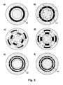
- FIG. 3 an alternative fluid guide is shown within a mixing stage of a mixer according to the invention with reference to a sequence of successive cross-sections in the flow direction.
- an azimuthal segmentation of the incoming ring current and an alternating radial offset of the resulting sub-channels takes place ( Fig. 3a and b ).
- adjacent sub-channels are offset in opposite azimuthal direction so that they overlap at least approximately completely azimuthally ( Fig. 2c ).
- the sub-channels are stretched so far in the azimuthal direction that at the end of the mixing stage a (possibly segmented) ring flow is again achieved ( Fig. 2d to f ).
- FIG. 4 illustrates substantially the same fluid management within a mixing stage of a mixer according to the invention, but also provides the sequence of sub-channel courses in the subsequent mixing stage ( Fig. 4f to i
- the azimuthal offset of radially displaced adjacent subchannels takes place in the opposite direction to the previous mixing stage.
- This form of fluid guidance in which the direction of the azimuthal offset alternates within successive mixing stages, is particularly preferred since this results in particularly good cross-mixing between the sub-channels along the mixing path.
- FIG. 5 shows a possible embodiment of the mixing section (detail) of a mixer according to the invention.
- This consists of a cylindrical, provided on its outer surface with channel structures core (20) and alternately pushed over inner (21) and outer (22) ring segments together, which results in the combination of the desired realization of the sub-channel guide (in the example shown in Fig. 2 sketched).
- FIG. 6 shows a perspective view of another possible embodiment of the mixing section of a mixer according to the invention (detail). This is composed of two different types of wedge-shaped cylinder segments, in whose side surfaces specific channel structure elements are introduced. In an alternating arrangement of the cylinder segments to a complete cylinder, the channel structure elements of the individual segments connect to the mixing structure of a mixing section according to the invention.
- FIG. 7 is a further possible embodiment of a mixing stage of the mixing section of a mixer according to the invention shown.
- the sub-channels are partially incorporated as a continuous openings or holes in different, preferably round, discs.
- the openings or bores form a coherent system of channels of a mixing section according to the invention.
- the disk stack is inserted for use in a suitable, eg tubular housing (not shown here), which optionally contains a mixer head and an outlet segment for supply and discharge of the process fluids.
Description
Die Erfindung betrifft einen hocheffizienten und skalierbaren Kompaktstatikmischer mit rotationssymmetrischer kaskadierter Mischstruktur sowie dessen Verwendung.The invention relates to a highly efficient and scalable compact static mixer with rotationally symmetrical cascaded mixed structure and its use.
Statische Mischer (oder "Statikmischer") dienen im Allgemeinen der Vermischung bzw. Dispergierung fluider Medien im kontinuierlichen Durchfluss. Sie sind dadurch gekennzeichnet, dass sie keine beweglichen Teile enthalten - die für die Vermischung benötigte Energie wird ausschließlich der Bewegung bzw. dem Druckgefälle der durch den Mischer hindurch fließenden Strömung entnommen. Das oder die zu vermischenden Medien treten dabei zunächst kontinuierlich, entweder getrennt parallel oder in mehr oder weniger definiert vorgemischter oder -laminierter Form, in den Mischer ein. Innerhalb des Mischers erfolgt dann die Vermischung der Gemischkomponenten durch ein- oder mehrfache Teilung, Verschiebung und Wiedervereinigung des Gemischstroms.Static mixers (or "static mixers") generally serve to mix or disperse fluid media in continuous flow. They are characterized in that they contain no moving parts - the energy needed for the mixing is taken only from the movement or the pressure gradient of the flowing through the mixer flow. The one or more media to be mixed initially enter the mixer continuously, either separately in parallel or in a more or less defined premixed or laminated form. Within the mixer, mixing of the mixture components is then carried out by single or multiple division, displacement and reunification of the mixture stream.
Als einstufige Statikmischer können beispielsweise alle Arten von Misch- und Dispergierdüsen oder -Blenden (z.B. solche gemäß
Im engeren Sinne werden allerdings solche Mischer als statische Mischer bezeichnet, bei denen die aktive Vermischung des Prozessmediums bzw. der Prozessmedien in mehreren Schritten bzw. sukzessive über eine gewisse Mischstrecke durch mehr oder weniger gezielt induzierte turbulente und/oder laminare Querströmungen (Turbulenz/Advektion) erfolgt, welche eine wiederholte Teilung, Scherung und/oder Faltung der Strömung bewirken. Diese Querströmungen werden durch definiert eingebrachte Umlenkungen, Aufteilungen und/oder Einbauten in dem als Mischstrecke fungierenden Fluidkanal hervorgerufen bzw. begünstigt. Die verschiedenen Typen von Statikmischern dieser Art unterscheiden sich im Wesentlichen in der Art und Form der Umlenkungen, Aufteilungen bzw. Einbauten in der Mischstrecke. So sind Systeme bekannt, die im Wesentlichen aus einem Rohr mit darin periodisch hintereinander angeordneten Blenden oder Düsen bestehen (z.B. Fig. 18-31 in
Mit kleiner werdenden Rohrquerschnitten wird aus prozesstechnischen (z.B. Druckverlust, Foulinganfälligkeit) wie auch aus fertigungstechnischen Gründen (Feinheit der Mischstrukturen) üblicherweise die Zahl der parallelen Stromteilungen reduziert, so dass man spätestens bei Erreichen von Teilkanalabmessungen deutlich unterhalb eines Millimeters ("Mikromischer") pro Mischstufe meist nur noch eine Aufteilung des Medienstroms auf zwei Teilströme vornimmt, welche dann verschoben oder versetzt wieder zusammengeführt werden (z.B.
Statikmischer zeichnen sich gegenüber dynamisch arbeitenden Rührwerken durch ihren sehr einfachen und kompakten Aufbau aus (keine beweglichen Teile; meist einfache Integration in das Verrohrungssystem einer Anlage). Gegenüber diskontinuierlich arbeitenden Mischern ("Rührkessel") bieten sie ferner mitunter deutliche zusätzliche Vorteile durch ihr geringes Prozessvolumen (kurze Verweilzeit) sowie eine schnellere und energie-effizientere Vermischung. Durch die intensive Quervermischung (schneller Fluidaustausch zwischen Wand- und Kernbereichen), den kompakten Strömungsquerschnitt und ein großes Oberfläche-VolumenVerhältnis der Mischstrecke bieten Statikmischer zudem oft wesentlich günstigere Bedingungen für den Wärmeaustausch des Gemischs mit den Mischwänden als andere Mischsysteme, wodurch sie sich auch für Mischaufgaben mit gleichzeitiger Gemischtemperierung, reine Temperieraufgaben oder als kontinuierlich arbeitende Reaktoren mit permanenter Durchmischung und somit engem Verweilzeitspektrum, z.B. für die Durchführung exothermer oder endothermer (chemischer) Reaktionen, besonders gut eignen.Static mixers are characterized by their very simple and compact design (no moving parts, usually simple integration into the piping system of a plant) compared to dynamic agitators. Compared with discontinuous mixers ("stirred tank"), they also offer significant additional advantages due to their low process volume (short residence time) as well as faster and more energy-efficient mixing. Due to the intensive cross-mixing (fast fluid exchange between wall and core areas), the compact flow cross-section and a high surface-to-volume ratio of the mixing section, static mixers often offer much more favorable conditions for the heat exchange of the mixture with the mixing walls than other mixing systems, making them suitable for mixing tasks with simultaneous mixture tempering, pure tempering tasks or as continuously operating reactors with permanent mixing and thus a narrow residence time spectrum, eg particularly suitable for the performance of exothermic or endothermic (chemical) reactions.
Intensiviert werden diese Vorteile in vielen Fällen durch Reduktion der charakteristischen Dimensionen (z.B. Kanal-/Mischstrukturabmessungen) der Mischstrecke. Hierdurch werden Diffusionswege für den Stoff- und Wärmetransport reduziert und somit Misch- und Wärmetauschvorgänge mitunter stark beschleunigt. In engen Kanalstrukturen liegen ferner auch über einen sehr breiten Bereich von Strömungsgeschwindigkeiten laminare und damit sehr definierte Strömungsverhältnisse vor, die eine besonders gleichmäßige und gezielte Gemischbildung bei minimiertem Energieeintrag ermöglichen. Übliche charakteristische laterale Mischstrukturdimensionen entsprechender Kleinst- und Mikro-Statikmischer liegen im Bereich weniger Zehntelmillimeter bis ca. 1,5 mm und der Gesamtquerschnitt eines einzelnen Mischkanals ist meist auf Werte von ca. 10 mm2 bis hin zu unter 1 mm2 beschränkt. Dem entsprechend ist der mögliche Durchsatz eines solchen Kleinst- oder Mikrostatikmischers bei gegebenem eingangsseitigem Förderdruck deutlich limitiert. So überschreiten übliche Massenströme, welche in derartigen Mischern vermischt werden, selten Werte von einigen 10 kg/h und decken damit für die meisten Anwendungen bestenfalls den Produktdurchsatz im Labor- und Technikumsmaßstab ab.These advantages are intensified in many cases by reducing the characteristic dimensions (eg channel / mixed structure dimensions) of the mixing section. As a result, diffusion paths for mass and heat transport are reduced and thus mixing and heat exchange processes are sometimes greatly accelerated. Furthermore, in narrow channel structures, even over a very wide range of flow velocities there are laminar and therefore very defined flow conditions, which are particularly uniform and targeted Allow mixture formation with minimized energy input. Typical characteristic lateral mixed structure dimensions of corresponding micro and micro static mixers are in the range of a few tenths of a millimeter to about 1.5 mm and the total cross section of a single mixing channel is usually limited to values of about 10 mm 2 down to less than 1 mm 2 . Accordingly, the possible throughput of such a micro or micro static mixer for a given input-side delivery pressure is significantly limited. For example, common mass flows blended in such mixers rarely exceed levels of tens of kg / hr and, for most applications, will at best cover the product throughput on the laboratory and pilot plant scale.
Um höhere Mediendurchsätze zu realisieren, ohne die spezifischen Vorteile eines (ggf. im Labormaßstab optimierten) Kleinst- bzw. Mikrostatikmischers wieder zu verlieren, ist es nahe liegende Praxis, mehrere identische Mischstrukturen (Kanäle) parallel zu schalten. Da die Vermischung in jeder einzelnen dieser Mischstrukturen stofflich getrennt von derjenigen in den anderen Mischstrukturen abläuft, ist es in diesem Fall notwendig, die zu vermischenden Komponenten am Eingang jeder einzelnen der individuellen parallelen Mischstrukturen mit dem jeweils selben Mengenverhältnis (Massenstromverhältnis) einzuspeisen. Eine hinreichend gute Gleichverteilung der Medienströme ist aufgrund der fertigungs- und prozessbedingten Durckverlustvariationen zwischen den einzelnen Mischstrukturen dabei fast immer mit zusätzlichem technischen Aufwand verbunden. So werden im einfachsten Fall als zusätzliche Elemente z.B. Drosselblenden oder Kanalstrukturen mit sehr präzise definiertem Druckabfall in das Fluidverteilungssystem vor den Mischstrukturen eingebracht, in anspruchsvolleren Fällen kann es sogar notwendig sein, jede Mischstruktur mit einem individuellen Massenstromregler zu versehen. In jedem Fall generieren diese zusätzlichen Elemente neben erhöhten Kosten einen oft nicht unerheblichen zusätzlichen Druckverlust und erhöhen die Anfälligkeit des Mischersystems gegenüber Verstopfungen und anderen möglichen Fehlerursachen.In order to realize higher media throughputs without losing the specific advantages of a miniaturized or micro static mixer (possibly optimized on a laboratory scale), it is obvious practice to connect several identical mixing structures (channels) in parallel. Since the mixing in each individual of these mixed structures proceeds materially separate from that in the other mixed structures, it is necessary in this case to feed the components to be mixed at the inlet of each individual one of the individual parallel mixing structures with the respective same ratio (mass flow ratio). A sufficiently good uniform distribution of the media streams is almost always associated with additional technical complexity due to the manufacturing and process-related Durckverlustvariationen between the individual mixed structures. Thus, in the simplest case, as additional elements e.g. Orifice plates or channel structures introduced with very precisely defined pressure drop in the fluid distribution system in front of the mixing structures, in more demanding cases, it may even be necessary to provide each mixing structure with an individual mass flow controller. In any case, in addition to increased costs, these additional elements often generate a not insignificant additional pressure loss and increase the susceptibility of the mixer system to blockages and other possible causes of faults.
Neben dem Mengenstromverhältnis kann insbesondere bei Kleinst- und Mikrostatikmischem auch das Strömungsbild am Eingang der einzelnen Mischstruktur signifikanten Einfluss auf das Mischergebnis haben. So wird beispielsweise bei Einspeisung eines laminaren Stromes zweier Eduktmedien in einen Kaskadenmischer nur dann ein gutes Mischergebnis bis zum Ende der Mischstrecke erreicht, wenn die anfängliche Trennebene zwischen den Eduktmedien weitest gehend senkrecht zur ersten Teilungsebene im Mischer liegt. Diesem Umstand ist bei der Parallelschaltung mehrerer identischer Mischstrukturen ggf. ebenfalls Rechnung zu tragen.In addition to the flow rate ratio, the flow pattern at the entrance of the individual mixing structure can have a significant influence on the mixing result, especially in the case of very small and micro static mixers. Thus, for example, when a laminar flow of two educt media is fed into a cascade mixer, a good mixing result is only achieved until the end of the mixing section if the initial parting plane between the educt media is largely perpendicular to the first parting plane in the mixer. This circumstance may also be taken into account when connecting several identical mixed structures in parallel.
Vor dem Hintergrund dieser Problematik stellt sich daher die Aufgabe, einen Statikmischer zu beschreiben, der nach einfachen Prinzipien und mit geringem technischen Aufwand über einen breiten Mengestrombereich skaliert werden kann, ohne die charakteristischen Dimensionen seiner Mischstrukturen zu variieren und zusätzliche Druckverlust verursachende Elemente zu erfordern. Die Aufgabe wird überraschenderweise gelöst durch den im Folgenden beschriebenen Statikmischer.Against the background of this problem, therefore, the task arises to describe a static mixer, the simple principles and with little technical effort over a can be scaled to a wide range of size without varying the characteristic dimensions of its mixed structures and requiring additional pressure loss inducing elements. The object is surprisingly achieved by the static mixer described below.
Gegenstand der Erfindung ist daher ein Statischer Mischen gemäß Anspruch 1, umfassend eine vom fluiden Mischgut sequenziell durchströmte koaxiale Anordnung von mehreren Mischstufen, jede einzelne davon enthaltend einen ggf. azimutal segmentierten Ringkanal, der jeweils in eine gerade Anzahl annähernd gleich großer Teilkanäle übergeht, welche entlang der Strömungsrichtung zunächst einen alternierenden radialen Versatz durchlaufen bis benachbarte Teilkanäle radial nicht mehr überlappen, dann durch azimutale Verschiebung und/oder Verbreiterung zu radial ineinander geschachtelten, ggf. azimutal segmentierten Ringkanälen ausgezogen werden, welche schließlich am Ende der jeweiligen Mischstufe durch radiale Verschmelzung wieder zu einem ggf. azimutal segmentierten Ringkanal zusammen laufen (s.
Als fluide Medien (Mischgut) im Sinne der Erfindung werden homogene Flüssigkeiten und Gase (auch Lösungen und Stoffe in der überkritischen Phase) ebenso wie fließfähige (ggf. auch strukturviskose) mehrphasige Gemische, z.B. Suspensionen, Emulsionen, Gas-flüssig-Gemische in jeglichem Mischungsverhältnis und jeder möglichen Strömungsform verstanden.For the purposes of the invention, fluid fluids (mixtures) are homogeneous liquids and gases (also solutions and substances in the supercritical phase) as well as flowable (and possibly pseudoplastic) multiphase mixtures, e.g. Suspensions, emulsions, gas-liquid mixtures understood in any mixing ratio and every possible flow form.
Durch die gegenseitige azimutale Verschiebung der Teilkanäle innerhalb der Mischstufen wird erreicht, dass zwischen jeweils benachbarten Kanälen ein Stoffaustausch stattfindet. Über eine zunehmende Anzahl von Mischstufen hinweg kommuniziert dadurch jeder Teilkanal mit einer zunehmenden Anzahl von Nachbarn höherer Ordnung, womit evtl. am Eintritt zu ersten Mischstufe entlang des Umfangs vorliegende Schwankungen im Mischungsverhältnis sukzessive ausgeglichen werden. Auch lokale Störungen, wie sie z.B. durch Ablagerungen oder Verstopfungen in einzelnen Teilkanälen verursacht werden, wirken sich hierdurch weitaus weniger auf den Druckabfall und das Mischergcbnis aus, als dies bei paralleler Führung getrennter Mischkanäle der Fall wäre. Die ringförmige Anordnung der Teilkanäle entlang der Mischstrecke sorgt dabei dafür, dass es keine Randzonen gibt, an denen der transversale Stofffluss unterbrochen würde. Sie begünstigt zudem eine sehr kompakte und druckstabile Bauweise des Mischers in einem zylindrischen Rohrmantel. Nach Durchlaufen einer Anzahl von Mischstufen, die etwa der halben Anzahl von Teilkanälen pro Mischstufe entspricht, hat jeder Teilkanal mit jedem anderen unmittelbaren oder mittelbaren Stoffaustausch gehabt. Ein besonders guter Ausgleich anfänglicher azimutaler Variationen im Mischungsverhältnis wird folglich erreicht, wenn die Anzahl der Mischstufen wenigstens der halben Anzahl von Teilkanälen innerhalb der (ersten) Mischstufen entspricht.The mutual azimuthal displacement of the sub-channels within the mixing stages ensures that a mass transfer takes place between adjacent channels. Over an increasing number of mixing stages, each sub-channel thereby communicates with an increasing number of higher-order neighbors, whereby any fluctuations in the mixing ratio which may be present at the entrance to the first mixing stage along the circumference are successively compensated. Also, local disturbances, such as those caused by deposits or blockages in individual sub-channels, thereby have far less impact on the pressure drop and the Mischerkcbnis, as would be the case with parallel management of separate mixing channels. The annular arrangement of the sub-channels along the mixing section ensures that there are no edge zones at which the transverse flow of material would be interrupted. It also favors a very compact and pressure-stable design of the mixer in a cylindrical tube jacket. After passing through a number of mixing stages corresponding to about half the number of sub-channels per mixing stage, each sub-channel has had with each other a direct or indirect mass transfer. A particularly good balance of initial azimuthal variations in the mixing ratio is consequently achieved if the number of mixing stages corresponds to at least half the number of partial channels within the (first) mixing stages.
Der Ringkanal am Ein- und Ausgang jeder Mischstufe kann in azimutaler Richtung sowohl durchgehend als auch von vornherein in Teilkanäle unterteilt (segmentiert) ausgeführt sein. Im Falle einer segmentierten Ausführung liegen die Teilkanäle zumindest in einer ringförmigen Anordnung um eine gemeinsame Achse in dem Sinne, dass die Mittelpunkte ihrer Querschnitte in wenigstens einer Querschnittsebene jeder Mischstufe in etwa auf einem Kreis liegen. Die Kanalbegrenzungen, durch welche die Unterteilung zustand kommt, sind dabei vorzugsweise in azimutaler Richtung deutlich (um wenigstens Faktor 0,5) schmaler als die Teilkanäle selbst. Im Falle einer segmentierten Ausführung ist es im allgemeinen vorteilhaft, wenn die Teilkanäle beim Übergang von einer Mischstufe in die darauf folgende ohne Versatz oder Stufen fortgeführt werden, womit insbesondere die Anzahl der Kanalsegmente in aufeinender folgenden Mischstufen gleich sein sollte.The annular channel at the input and output of each mixing stage can be divided (segmented) in the azimuthal direction both continuously and from the outset in sub-channels executed. In the case of a segmented embodiment, the sub-channels are at least in an annular arrangement about a common axis in the sense that the centers of their cross sections in at least one cross-sectional plane of each mixing stage are approximately on a circle. The channel boundaries through which the subdivision comes about are preferably narrower in the azimuthal direction (by at least a factor 0.5) than the subchannels themselves. In the case of a segmented embodiment, it is generally advantageous if the subchannels during the transition from a mixing stage be continued into the following without offset or stages, which in particular the number of channel segments in aufeinender following mixing stages should be the same.
Der in azimutaler Richtung alternierende radiale Versatz der Teilkanäle innerhalb der Mischstufen kann ausschließlich durch Führung jedes zweiten Teilkanals zur Mischerachse hin oder von dieser weg wie auch durch simultane (alternierende) Variation des radialen Versatzes benachbarter Teilkanäle realisiert werden. Am Ende der Versatzstrecke muss jedoch die innere Begrenzungsfläche der weiter außen liegenden Teilkanäle einen mindestens so großen oder größeren Abstand zur Mischerachse aufweisen als die äußere Begrenzungsfläche der weiter innen liegenden Teilkanäle.The alternating in the azimuthal direction radial offset of the sub-channels within the mixing stages can be realized exclusively by guiding each second sub-channel to the mixer axis or away from this as well as by simultaneous (alternating) variation of the radial offset of adjacent sub-channels. At the end of the offset distance, however, the inner boundary surface of the further outer sub-channels must have an at least as large or larger distance to the mixer axis than the outer boundary surface of the further inner sub-channels.
Der Übergang der innerhalb einer Mischstufe durch alternierenden radialen Versatz abwechselnd auf zwei radiale Ebenen verteilten Teilkanäle zu zwei konzentrischen, ggf. bis zum Ende der Mischstufe durchgängig azimutal segmentierten Ringkanälen erfolgt durch azimutale Verbreiterung der Teilkanäle entlang des Strömungsverlaufs, der ein - bevorzugt zwischen den beiden Ebenen gegenläufiger - azimutaler Versatz der Teilkanäle vorgeschaltet oder überlagert sein kann. Vorzugsweise ist der azimutalen Verbreiterung der Teilkanäle dabei eine simultane radiale Verjüngung überlagert. Besonders bevorzugt wird durch diese simultane Änderung der azimutalen und radialen Ausdehnung der Teilkanäle deren Querschnitt entlang des Strömungsverlaufs wenigstens annähernd konstant gehalten.The transition of the subchannels, which are alternately distributed over two radial planes within a mixing stage to two concentric, optionally azimuthally segmented annular channels up to the end of the mixing stage, takes place by azimuthal broadening of the subchannels along the course of the flow, preferably between the two planes opposite - azimuthal offset of the sub-channels upstream or can be superimposed. Preferably, the azimuthal broadening of the sub-channels is superimposed on a simultaneous radial taper. With particular preference, this simultaneous change in the azimuthal and radial extent of the subchannels keeps their cross section along the flow path at least approximately constant.
In gewissen Fällen, insbesondere wenn im Verlauf der Vermischung die Viskosität des Gemischs (zumindest gegenüber einer seiner Ausgangskomponenten) signifikant abnimmt, kann es im Gegensatz zu der allgemein als vorteilhaft eingestuften Kontinuität der Segmentierung bzw. Kanalzahl und des Kanalquerschnitts über die verschiedenen Mischstufen hinweg auch vorteilhaft sein, die Anzahl der parallelen Kanäle von einer Mischstufe zu einer darauf folgenden zu steigern und dabei parallel die Abmessungen der Kanäle zu verringern. In diesem Fall erscheint es besonders vorteilhaft, zwischen den aufeinander folgenden Mischstufen mit unterschiedlicher Kanalzahl ein unsegmentiertes Stück Ringkanal in die Mischstrecke einzusetzen oder die Kanalzahl in der stromabwärts gelegenen der beiden Mischstufen gegenüber der stromaufwärts gelegenen um ein ganzzahliges Vielfaches zu erhöhen, so dass sich an jeden Kanal bzw. jedes Kanalsegment aus der stromaufwärts gelegenen Mischstufe eine jeweils gleiche Zahl und Anordnung von stromabwärts gelegenen Kanälen bzw. Segmenten anschließt.In certain cases, especially if the viscosity of the mixture (at least with respect to one of its starting components) decreases significantly in the course of mixing, it may also be advantageous over the various mixing stages, in contrast to the generally considered advantageous continuity of the segmentation or channel number be to increase the number of parallel channels from one mixing stage to a subsequent, while reducing the dimensions of the channels in parallel. In this case it seems particularly advantageous to have different ones between successive mixing stages Number of channels to use an unsegmented piece of annular channel in the mixing section or increase the number of channels in the downstream of the two mixing stages relative to the upstream by an integer multiple, so that each channel or each channel segment from the upstream mixing stage a respective number and Arrangement of downstream channels or segments connects.
Aufgrund von strömungstechnischen Erwägungen erscheint es vorteilhaft, die transversalen Abmessungen der Teilkanäle in einem Verhältnis kleiner 5, besonders bevorzugt kleiner 2 zueinander zu wählen und die Länge einer einzelnen Mischstufe so auszulegen, dass sie, gemessen in der Hauptströmungsrichtung des Gemischs (diese entspricht in der Regel der Axialrichtung der Mischstrecke), bevorzugt dem Zwei- bis Zehnfachen, besonders bevorzugt dem Drei- bis Sechsfachen der größten radialen Ausdehnung der Teilkanäle entspricht.Due to fluidic considerations, it seems advantageous to choose the transverse dimensions of the sub-channels in a ratio smaller than 5, more preferably smaller than 2 and the length of a single mixing stage interpreted as being measured in the main flow direction of the mixture (this usually corresponds the axial direction of the mixing section), preferably two to ten times, particularly preferably three to six times, corresponds to the greatest radial extent of the sub-channels.
Die absoluten Abmessungen der Teilkanäle sowie deren Anzahl innerhalb einer Mischstufe sollten sich bevorzugt an der Mischaufgabe, insbesondere am Gemischdurchsatz, der Viskosität des Gemischs, evtl. der Größe und Menge im Gemisch vorhandener fester Bestandteile und ggf. einer vorgegebenen Verweilzeit des Gemischs im Mischer, jeweils unter Berücksichtigung des zulässigen Druckverlustes über die Mischstrecke orientieren. Bei einer temperierten Ausführung des Mischers kann auch die geforderte Wärmeübertragungsleistung ein Kriterium für die Auslegung sein. Sofern z.B. in möglichst kurzer Zeit eine besonders intensive Vermischung niedrig viskoser Komponenten erreicht werden soll, ist es in der Regel vorteilhaft, möglichst kleine Teilkanäle zu wählen und deren parallele Anzahl innerhalb der Mischstufen dem gewünschten Gemischdurchsatz und Druckabfall anzupassen. Die Anzahl der Mischstufen kann in diesem Fall aufgrund der bereits in den ersten Mischstufen erreichten guten Gemischhomogenität relativ klein gehalten werden, wobei sie die Zahl der parallelen Teilkanäle innerhalb der Mischstufen vorzugsweise um nicht mehr als einen Faktor von ca. 0,3 unterschreiten sollte, um eine hinreichende Toleranz des Mischers gegenüber Fehlverteilungen im Mischungsverhältnis und Störungen innerhalb der Mischstrecke zu gewährleisten. Insbesondere beim Übergang zu hohen Gemischdurchsätzen, hohen Viskositäten oder bei Einsatz oder Erzeugung partikelhaltiger Gemische kann - ggf. zusätzlich zur Erhöhung der Zahl paralleler Teilkanäle - eine Vergrößerung deren transversaler Abmessungen erforderlich sein. Die damit verbundene Verringerung der erreichten Mischqualität gegenüber einem Mischer mit kleineren Kanaldimensionen kann in gewissen Grenzen durch die Erhöhung der Anzahl der Mischstufen kompensiert werden. Beide Maßnahmen führen naturgemäß - insbesondere in Kombination - zu einer Erhöhung des Fluidvolumens der Mischstrecke und damit zu einer Vergrößerung der Verweilzeit des Gemischs darin. Die Vermischungsgeschwindigkeit wird folglich hierdurch herabgesetzt. Auf Basis dieser Überlegungen liegen in der Praxis sinnvolle transversale Teilkanalabmessungen bevorzugt im Bereich zwischen 0,1 und 20 mm, besonders bevorzugt im Bereich von 0,5 mm bis 5 mm.The absolute dimensions of the sub-channels as well as their number within a mixing stage should preferably be at the mixing task, in particular at the mixture flow rate, the viscosity of the mixture, possibly the size and amount in the mixture of existing solid components and optionally a predetermined residence time of the mixture in the mixer, respectively Orientate over the mixing section taking into account the permissible pressure drop. In a tempered version of the mixer and the required heat transfer performance may be a criterion for the interpretation. If, for example, a particularly intensive mixing of low-viscosity components is to be achieved in the shortest possible time, it is generally advantageous to select the smallest possible partial channels and to adjust their parallel number within the mixing stages to the desired mixture throughput and pressure drop. In this case, the number of mixing stages can be kept relatively small due to the good mixture homogeneity already achieved in the first mixing stages, wherein it should preferably not fall below the number of parallel partial channels within the mixing stages by more than a factor of approximately 0.3 to ensure a sufficient tolerance of the mixer against incorrect distributions in the mixing ratio and disturbances within the mixing section. In particular, in the transition to high mixture flow rates, high viscosities or when using or generating particle-containing mixtures can - possibly in addition to increasing the number of parallel sub-channels - an increase in their transverse dimensions may be required. The associated reduction of the achieved mixing quality compared to a mixer with smaller channel dimensions can be compensated within certain limits by increasing the number of mixing stages. Both measures naturally lead, in particular in combination, to an increase in the fluid volume of the mixing section and thus to an increase in the residence time of the mixture therein. The mixing speed is consequently reduced thereby. Based on this Considerations are in practice meaningful transverse sub-channel dimensions preferably in the range between 0.1 and 20 mm, more preferably in the range of 0.5 mm to 5 mm.
Der erfindungsgemäße Statikmischer kann für unterschiedliche verfahrenstechnische Aufgaben vorteilhaft genutzt werden. Beispielsweise kann in ihm ein Gemisch aus mehreren zunächst getrennt vorliegenden fluiden Komponenten erzeugt werden. In diesem Falle ist der eigentlichen Mischstrecke bevorzugt ein Mischerkopf voranzuschalten, welcher die zu vermischenden Komponenten in einen radial geschichteten Ringstrom überführt. Diese Ausführungsform ist für den Fall von zwei unterschiedlichen Medien in
Im Falle, dass ein höher viskoses Medium mit einem deutlich niedriger viskosen Medium vermischt werden soll, kann es ferner vorteilhaft sein, einen erfindungsgemäßen Mischer für drei Eingangsströme zu verwenden, den Strom des niedriger viskosen Mediums in zwei in etwa gleich große Ströme aufzuteilen und diese mit dem höher viskosen Strom so in den Mischer einzuspeisen, dass am Anfang der Mischstrecke ein Ringstrom erzeugt wird, bei welchem das niedriger viskose Medium jeweils den inneren und den äußeren Ring bilden, während das höher viskose Medium im mittleren Ring strömt.In the event that a more viscous medium to be mixed with a much lower viscous medium, it may also be advantageous to use a mixer according to the invention for three input streams, divide the flow of the lower viscous medium into two approximately equal currents and these with the higher viscous stream to be fed into the mixer, that at the beginning of the mixing section, a ring flow is generated, wherein the lower viscous medium each form the inner and the outer ring, while the higher viscous medium flows in the middle ring.
In einem anderen Fall der Verwendung des erfindungsgemäßen Mischers liegt das Gemisch bereits in vorvermischter Form vor. In diesem Fall kann der Mischerkopf vereinfacht ausgeführt werden und reduziert sich vorzugsweise auf einen Einlassstutzen zur Mischstrecke (siehe
Aufgrund der intensiven Quervermischung des Gemischstroms beim Durchlaufen des erfindungsgemäßen Statikmischers ist hierin neben dem intensivierten Stofftransport auch ein besonders guter Wärmeaustausch zwischen dem Gemischstrom und den Wänden der Mischstrecke gegeben. Über die Variation der Anzahl paralleler Teilkanäle innerhalb der Mischstufen bei konstant gehaltenem Teilkanalquerschnitt und somit festem Verhältnis von Oberfläche zu Volumen- steht dabei eine Möglichkeit zur Durchsatzskalierung des Mischers bei gleichbleibend gutem Wärmeaustausch zur Verfügung, welche bei der Skalierung der bekannten Statikmischer über den Querschnitt der Mischstrecke in der Regel nicht gegeben ist. Der Mischer eignet sich somit auch besonders gut zur Temperierung des Gemischs während der Vermischung. So kann beispielsweise die Temperatur des Gemischs gezielt gehalten, während der Vermischung erhöht oder abgesenkt werden, z.B. um die Viskosität des Gemischs oder einzelner Komponenten einzustellen, Stoffaustauschvorgänge zu beeinflussen, die Löslichkeit einzelner Gemischbestandteile gezielt zu variieren oder die Geschwindigkeit chemischer, physikalischer oder biologischer Vorgänge im Gemisch zu steuern.Due to the intensive cross-mixing of the mixture flow when passing through the static mixer according to the invention is in addition to the intensified mass transport and a particularly good heat exchange between the mixture flow and the walls of the mixing section given. By varying the number of parallel subchannels within the mixing stages while maintaining the subchannel cross section and thus fixed surface to volume ratio, there is a possibility for throughput scaling of the mixer with consistently good heat exchange, which in the scaling of the known static mixer over the cross section of the mixing section usually not given. The mixer is thus also particularly suitable for tempering the mixture during mixing. For example, the temperature of the mixture may be kept targeted, increased or decreased during mixing, e.g. to adjust the viscosity of the mixture or individual components, to influence mass transfer processes, to selectively vary the solubility of individual mixture components or to control the rate of chemical, physical or biological processes in the mixture.
Eine temperierte Ausführung des Mischers kann ferner besonders vorteilhaft insbesondere zur Durchführung exothermer oder endothermer chemischer Reaktionen eingesetzt werden. Innerhalb des Mischers können dabei eine oder mehrere Stufen des Prozesses in Folge oder teilweise ineinander übergehend parallel ablaufen: Die Bildung des Reaktionsgemischs aus den Reaktanden, die Einstellung der Reaktionstemperatur (z.B. zur Einleitung der Reaktion) und/oder die Führung der Reaktion oder eines Teils davon unter definierten und homogenen Temperatur- und Konzentrationsbedingungen.A tempered version of the mixer can also be used particularly advantageously in particular for carrying out exothermic or endothermic chemical reactions. Within the mixer, one or more stages of the process may take place in succession or partly in parallel: the formation of the reaction mixture from the reactants, the adjustment of the reaction temperature (eg to initiate the reaction) and / or the management of the reaction or a part thereof under defined and homogeneous temperature and concentration conditions.
Die Temperierung des Mischers kann beispielsweise vorteilhaft durch in oder um die Außenwände der Mischstrecke sowie ggf. in deren Kern eingebrachte Kanäle realisiert werden, welche im Betrieb von einem fluiden Temperiermedium, wie es dem Fachmann auf dem Gebiet der Wärmetauschertechnik bekannt ist, durchströmt werden. Alternativ ist eine elektrische Beheizung des Mischermantels (und ggf. des Kerns) z.B. durch Widerstandsheizelemente oder auf induktivem Wege möglich. Auch andere Methoden der Beheizung oder Kühlung, wie z.B. Bestrahlung mit Infrarotlicht oder Mikrowellen, der Einsatz von Peltierelementen oder die Durchströmung von Temperierkanälen mit exotherm oder endotherm reaktiven Gemischen können in gewissen Einsatzfällen des Mischers vorteilhaft sein.The temperature of the mixer can be advantageously realized, for example, by channels introduced into or around the outer walls of the mixing section and optionally in its core, which in operation are flowed through by a fluid temperature control medium, as known to those skilled in the art of heat exchanger technology. Alternatively, electrical heating of the mixer jacket (and possibly of the core) is possible, for example, by resistance heating elements or by inductive means. Other methods of heating or cooling, such as irradiation with infrared light or microwaves, the use of Peltier elements or the flow of Temperierkanälen with exothermic or endothermic reactive mixtures may be advantageous in certain applications of the mixer.
Als Konstruktionsmaterialien für den Aufbau des erfindungsgemäßen Mischers kommen grundsätzlich alle für die jeweilige Anwendung (z.B. hinsichtlich Festigkeit, chemischer und thermischer Beständigkeit, Bearbeitbarkeit, Wärmeleitfähigkeit, Wärmeausdehnung etc.) geeigneten Materialien infrage. Bei Anwendungen mit hohen Anforderungen an die mechanische, thermische und chemische Beständigkeit, wie sie häufig im Bereich der chemischen Verfahrenstechnik auftreten, kommen bevorzugt korrosionsbeständige Metalle wie z.B. Edelstähle, Nickelbasis-Legierungen, Titan(-legierungen) oder Refraktärmetalle sowie Keramiken (z.B. Aluminiumoxid, Zirkonoxid, Siliziumnitrid oder Siliziumcarbid), Fluorkunststoffe (z.B. PTFE, PFA etc.) und Fluorelastomere (z.B. FFKM, FKM -vorwiegend als Dichtungsmaterialien) zum Einsatz. Bei geringen Anforderungen an die chemische Beständigkeit und mäßigen Anforderungen an die thermische und mechanische Stabilität kann auch der Einsatz von preiswerteren und in der Regel leichter zu bearbeitenden NE-Metallen wie z.B. Aluminium-, Kupfer- oder Messingwerkstoffen vorteilhaft sein. Sind die Anforderungen an die Druck- und Temperaturstabilität noch geringer, lassen sich auch Kunststoffe - u.a. aufgrund ihrer guten Bearbeitbarkeit - bevorzugt für den Aufbau eines erfindungsgemäßen Mischers einsetzen.As construction materials for the construction of the mixer according to the invention, in principle all materials suitable for the respective application (for example with regard to strength, chemical and thermal resistance, workability, thermal conductivity, thermal expansion, etc.) are suitable. For applications with high mechanical, thermal and chemical resistance requirements, which frequently occur in the field of chemical engineering, it is preferable to use corrosion-resistant metals, such as e.g. Stainless steels, nickel base alloys, titanium (alloys) or refractory metals, and ceramics (e.g., alumina, zirconia, silicon nitride, or silicon carbide), fluoroplastics (e.g., PTFE, PFA, etc.), and fluoroelastomers (e.g., FFKM, FKM-primarily as sealing materials). With low requirements on the chemical resistance and moderate requirements for thermal and mechanical stability, the use of less expensive and usually easier to process non-ferrous metals such. Aluminum, copper or brass materials be advantageous. If the requirements for pressure and temperature stability are even lower, plastics can also be used - i.a. due to their good machinability - preferably used for the construction of a mixer according to the invention.
Eine bevorzugte Ausführungsform des Mischers bzw. seiner Mischstrecke setzt sich aus einem konus- oder zylinderförmigen Kernelement (20) mit darin eingebrachten Kanalstrukturen, einer ersten Anordnung von mehreren über diesen Kern geschobenen, hintereinander angeordneten, mit im Wesentlichen axial verlaufenden Kanalstrukturen versehenen inneren Ringelementen (21) und einer zweiten hierzu koaxialen Anordnung von mit der ersten Anordnung auf Stoß überlappenden äußeren Ringelementen (22) zusammen, welche von einen druck- und fluiddichten, rohrförmigen Mantel umschlossen werden (s.
Eine weitere bevorzugte Ausführungsform des Mischers bzw. seiner Mischstrecke ist aus keilförmigen Zylindersegmenten aufgebaut, welche um eine gemeinsame Achse angeordnet einen Zylinder (ggf. auch Hohlzylinder) ergeben. In die Seitenflächen der Zylindersegmente sind Materialschnitte (Vertiefungen) eingebracht, welche im zylinderförmigen Zusammenbau der Segmente eine erfindungsgemäße Mischstruktur ergeben (
Durch die wiederholte Teilung und Umschichtung des - ggf. eingangsseitig geschichteten - Prozessfluidstroms entlang der Mischstrecke können über eine leicht zu realisierende Anzahl von Mischstufen (z.B. 5 bis 20) bis zum Mischerausgang theoretische Dicken der einzelnen Fluidschichten im Bereich weniger 0,01 mm oder noch darunter realisiert werden. Bei entsprechender Auslegung erreicht ein erfindungsgemäßer Mischer somit in vielen Fällen annähernd die Leistungsfähigkeit eines Multilaminations-Mikromischers mit vergleichbaren Druckabfall- und Durchflusswerten. Im Vergleich zu diesem weist der erfindungsgemäße Statikmischer jedoch um gut einen Faktor 5 bis 20 größere minimale Abmessungen der durchströmten Kanäle auf und ist folglich wesentlich weniger anfällig gegenüber Ablagerungen und Verstopfungen. So können mit einem erfindungsgemäßen Statikmischer u.a. auch vorteilhaft Medien verarbeitet werden, welche feste oder anderweitig nicht-fluide Bestandteile enthalten (z.B. Suspensionen, Slurries, Gele, Aufschwämmungen von Flocken etc.) oder in denen im Verlauf der Vermischung z.B. infolge chemischer Reaktionen solche nicht-fluiden Bestandteile (ggf. auch temporär) entstehen. So lässt sich ein erfindungsgemäßer Statikmischer beispielsweise besonders vorteilhaft zur Herstellung von Polymeren oder Polymergemischen, zur Vermischung wenigstens zweier fluider Medien, von denen wenigstens eines eine Suspension ist, oder zur Erzeugung von Suspensionen durch Fällung einsetzen.Due to the repeated division and redeployment of the - possibly stratified on the input side - process fluid flow along the mixing section can be easily realized on a number of mixing stages (
Die Erfindung wird anhand der folgenden Figuren beispielhaft erläutert ohne sie jedoch darauf zu beschränken.The invention will be described by way of example with reference to the following figures without however being limited thereto.
Es zeigen:
- Figur 1a bis c
- den grundsätzlichen Aufbau eines erfindungsgemäßen Mischers für verschiedene Anzahlen von zu vermischenden fluiden Medien im Längsschnitt,
- Figur 2a bis f
- Querschnitte eines erfindungsgemäßen Mischers an unterschiedlichen Positionen innerhalb einer Mischstufe,
- Figur 3a bis f
- Querschnitte eines erfindungsgemäßen Mischers mit alternativer Führung der Teilkanäle an unterschiedlichen Positionen innerhalb einer Mischstufe,
- Figur 4a bis i
- Querschnitte eines erfindungsgemäßen Mischers mit einer weiteren alternativen Führung der Teilkanäle an unterschiedlichen Positionen innerhalb einer Mischstufe, wobei der azimutale Versatz der Teilkanäle in aufeinander folgenden Mischstufen in entgegen gesetzter Richtung erfolgt,
Figur 5a und b- eine perspektivische Darstellung einer möglichen Ausführungsform der Mischstrecke eines erfindungsgemäßen Mischers (Ausschnitt) in zusammengebauter und explodierter Form und
Figur 6- eine perspektivische Darstellung einer weiteren möglichen Ausführungsform der Mischstrecke eines erfindungsgemäßen Mischers (Ausschnitt) in teilweise explodierter Form
- Figur 7
- eine weitere mögliche Ausführungsform einer Mischstufe der Mischstrake eines Mischers.
- FIGS. 1a to c
- the basic structure of a mixer according to the invention for different numbers of fluid media to be mixed in longitudinal section,
- FIGS. 2a to f
- Cross sections of a mixer according to the invention at different positions within a mixing stage,
- FIGS. 3a to f
- Cross sections of a mixer according to the invention with alternative guidance of the subchannels at different positions within a mixing stage,
- Figure 4a to i
- Cross sections of a mixer according to the invention with a further alternative guidance of the sub-channels at different positions within a mixing stage, wherein the azimuthal offset of the sub-channels in successive mixing stages takes place in the opposite direction,
- FIG. 5a and b
- a perspective view of a possible embodiment of the mixing section of a mixer according to the invention (detail) in assembled and exploded form and
- FIG. 6
- a perspective view of another possible embodiment of the mixing section of a mixer according to the invention (detail) in a partially exploded form
- FIG. 7
- a further possible embodiment of a mixing stage of the mixing of a mixer.
In
In
- 1.1.
- Mischstufemixer
- 2.Second
- Mischstreckemixing section
- 3.Third
- Mischerkopfmixer head
- 4.4th
- Auslasssegmentoutlet segment
- 5.5th
- Einlass für VorgemischInlet for premix
- 5a, 5b, 5c.5a, 5b, 5c.
- Einlässe für GemischkomponentenInlets for mixture components
- 6.6th
- MischerauslassMixer outlet
- 7.7th
- Vorgemischpremix
- 7a ,7b, 7c.7a, 7b, 7c.
- Gemischkomponenten (zu vermischende Medien)Mixture components (media to be mixed)
- 8.8th.
- Gemischmixture
- 10.10th
- Ringkanal am Eintritt zur MischstufeRing channel at the inlet to the mixing stage
- 11.11th
- Teilkanalsubchannel
- 12.12th
- (Unsegmentierter oder teilsegmentierter) Ringkanal am Austritt der Mischstufe/Eintritt zur folgenden Mischstufe(Unsegmented or partially segmented) ring channel at the outlet of the mixing stage / entry to the following mixing stage
- 13.13th
- Segmentierter Ringkanal (am Eintritt zur folgenden Mischstufe)Segmented ring channel (at the entrance to the following mixing stage)
- 20.20th
- Kernelementcore element
- 21.21st
- Inneres RingelementInner ring element
- 22.22nd
- Äußeres RingelementOuter ring element
Claims (11)
- Static mixer, comprising a coaxial arrangement of at least two mixing stages (1) flowed through sequentially by the material to be mixed, each individual one of which containing a, possibly azimuthally segmented, annular channel (10), wherein, in every mixing stage, this annular channel (10) in each case goes over into an even number of partial channels (11) of approximately the same size, which along the direction of flow initially go through an alternating radial offset until neighboring partial channels (11) no longer radially overlap, then are drawn out by azimuthal displacement and/or widening into radially interleaved, possibly azimuthally segmented, annular channels (12), which finally run together again at the end of the mixing stage, by radial fusion, to a, possibly azimuthally segmented, annular channel (13), characterized in that the transformation of the radially alternating partial channels (12) into possibly azimuthally segmented annular channels (13) takes place by azimuthal displacement and subsequent or simultaneous azimuthal widening.
- Static mixer according to Claim 1, characterized in that the first mixing stage (1) is preceded by a device (3) for feeding in at least two fluidic media (7), which transforms the media (7) to be fed in into a radially layered annular stream and introduces the latter into the annular inlet channel (10) of the first mixing stage (1).
- Static mixer according to either of Claims 1 and 2, characterized in that the annular channel (10) is already azimuthally segmented into an even number of partial channels (11) at the inlet and outlet of each mixing stage (1) and in that this segmentation is continued in the respectively following mixing stage (1) without steps.
- Static mixer according to one of Claims 1 to 3, characterized in that the number of mixing stages (1) corresponds to 0.3 to 0.7 of the number of partial channels (11) within a mixing stage.
- Static mixer according to one of Claims 1 to 4, characterized in that the hydraulic diameter of the partial channels (11) in the mixing stages (1) is not greater than 2 mm.
- Static mixer according to one of Claims 1 to 5, characterized in that the static mixer is equipped with a device for controlling the temperature of the media flowing through.
- Static mixer according to one of Claims 1 to 6, characterized in that the mixing section (2) thereof is made up of a conical or cylindrical core element (20) with channel structures introduced therein, a number of annular elements (21, 22) overlapping one another, pushed over this core, some with substantially axially extending channel structures, and an enclosing pressure- and fluid-tight, annular shell.
- Static mixer according to one of Claims 1 to 7, characterized in that the mixing section (2) thereof is made up of an even number of wedge-shaped cylinder segments, in the side areas of which channel structure portions which in the assembled state produce the arrangement and sequence of mixing channels according to the invention have been introduced.
- Use of a static mixer according to one of Claims 1 to 8 for producing polymers or polymer mixtures.
- Use of a static mixer according to one of Claims 1 to 8 for mixing at least two fluidic media, at least one of which is a suspension.
- Use of a static mixer according to one of Claims 1 to 8 for producing suspensions by precipitation.
Applications Claiming Priority (2)
| Application Number | Priority Date | Filing Date | Title |
|---|---|---|---|
| DE102009011996 | 2009-03-06 | ||
| PCT/EP2010/001104 WO2010099884A1 (en) | 2009-03-06 | 2010-02-23 | Coaxial compact static mixer and use thereof |
Publications (2)
| Publication Number | Publication Date |
|---|---|
| EP2403633A1 EP2403633A1 (en) | 2012-01-11 |
| EP2403633B1 true EP2403633B1 (en) | 2013-04-17 |
Family
ID=42227574
Family Applications (1)
| Application Number | Title | Priority Date | Filing Date |
|---|---|---|---|
| EP10706933.8A Active EP2403633B1 (en) | 2009-03-06 | 2010-02-23 | Coaxial compact static mixer and use thereof |
Country Status (5)
| Country | Link |
|---|---|
| US (1) | US8696193B2 (en) |
| EP (1) | EP2403633B1 (en) |
| JP (1) | JP2012519577A (en) |
| CN (1) | CN102355942B (en) |
| WO (1) | WO2010099884A1 (en) |
Cited By (1)
| Publication number | Priority date | Publication date | Assignee | Title |
|---|---|---|---|---|
| US11440033B2 (en) | 2017-12-29 | 2022-09-13 | Medmix Switzerland Ag | Mixer, multi-component dispenser, and method of dispensing multi-component material from a multi-component dispenser |
Families Citing this family (38)
| Publication number | Priority date | Publication date | Assignee | Title |
|---|---|---|---|---|
| US8967852B2 (en) * | 2010-09-17 | 2015-03-03 | Delavan Inc | Mixers for immiscible fluids |
| EP2663392B1 (en) * | 2011-01-12 | 2018-10-03 | Tetra Laval Holdings & Finance SA | Layer multiplier for fluids with high viscosity |
| JP6068926B2 (en) * | 2012-10-23 | 2017-01-25 | 矢崎総業株式会社 | Injection molding nozzle |
| US9795976B2 (en) * | 2013-01-07 | 2017-10-24 | 1,4Group, Inc. | Thermal fogger for creating stable aerosols |
| US9693958B2 (en) | 2013-03-15 | 2017-07-04 | Cureport, Inc. | Methods and devices for preparation of lipid nanoparticles |
| KR102098771B1 (en) * | 2013-08-14 | 2020-04-08 | 재단법인 포항산업과학연구원 | Recovery of NOx Gas into Nitric Acid by Using Micro-Bubble Type Scrubber |
| DE102013020469A1 (en) * | 2013-12-06 | 2015-06-11 | Webasto SE | Heat exchanger and method for producing a heat exchanger |
| FR3015315B1 (en) * | 2013-12-19 | 2016-02-12 | Bostik Sa | PROCESS FOR HOT APPLICATION OF SILYLATED ADHESIVE COMPOSITION |
| RU2553861C1 (en) * | 2014-03-12 | 2015-06-20 | Федеральное государственное бюджетное образовательное учреждение высшего профессионального образования "Тамбовский государственный технический университет" ФГБОУ ВПО ТГТУ | Hydrodynamic mixer |
| JP6128397B2 (en) * | 2014-08-27 | 2017-05-17 | 有限会社 開商 | Gas mixing equipment |
| US9470132B2 (en) | 2014-12-05 | 2016-10-18 | Cummins Emission Solutions, Inc. | Compact radial exterior exhaust assisted decomposition reactor pipe |
| US20160265779A1 (en) * | 2015-03-11 | 2016-09-15 | General Electric Company | Twin radial splitter-chevron mixer with converging throat |
| CN104786382B (en) * | 2015-04-24 | 2017-01-04 | 浙江省现代纺织工业研究院 | A kind of Double-conical-surface dynamic mixer |
| KR20160147482A (en) * | 2015-06-15 | 2016-12-23 | 삼성전자주식회사 | Apparatus for manufacturing Semiconductor Devices Having a Gas Mixing Part |
| US9732775B2 (en) * | 2015-06-24 | 2017-08-15 | The Boeing Company | Flow straightener apparatus and systems for ducted air |
| RU2611878C1 (en) * | 2015-11-05 | 2017-03-01 | Федеральное государственное бюджетное образовательное учреждение высшего образования "Красноярский государственный аграрный университет" | Vortex hydrodynamic mixer |
| EP3374070B1 (en) | 2015-11-13 | 2023-08-09 | Re Mixers, Inc. | Static mixer |
| CN105666720B (en) * | 2016-04-15 | 2017-12-22 | 河南省龙都生物科技有限公司 | PLA pre-polymerization mixing device |
| RU2618078C1 (en) * | 2016-04-25 | 2017-05-02 | Федеральное государственное бюджетное образовательное учреждение высшего образования "Тамбовский государственный технический университет" ФГБОУ ВО "ТГТУ" | Hydrodynamic mixer |
| RU2618865C1 (en) * | 2016-05-04 | 2017-05-11 | Федеральное государственное бюджетное образовательное учреждение высшего образования "Тамбовский государственный технический университет" ФГБОУ ВО "ТГТУ" | Hydrodynamic mixer |
| RU169527U1 (en) * | 2016-10-04 | 2017-03-22 | Виль Файзулович Галиакбаров | HYDRAULIC HYDRAULIC MIXER |
| RU2625874C1 (en) * | 2016-11-15 | 2017-07-19 | Федеральное государственное бюджетное образовательное учреждение высшего образования "Тамбовский государственный технический университет" (ФГБОУ ВО "ТГТУ") | Hydrodynamic mixer |
| RU171985U1 (en) * | 2016-11-15 | 2017-06-23 | Эмилия Вильевна Галиакбарова | FLOW INJECT MIXER |
| CN206730896U (en) * | 2017-01-13 | 2017-12-12 | 理星(天津)生物科技有限公司 | A kind of high pressure homogenizer |
| US11185830B2 (en) | 2017-09-06 | 2021-11-30 | Waters Technologies Corporation | Fluid mixer |
| JP2019084763A (en) * | 2017-11-07 | 2019-06-06 | 株式会社神戸製鋼所 | Mixing device |
| JP6831317B2 (en) * | 2017-11-07 | 2021-02-17 | 株式会社神戸製鋼所 | Mixer |
| RU180014U1 (en) * | 2018-02-21 | 2018-05-30 | Федеральное государственное бюджетное образовательное учреждение высшего образования "Уфимский государственный нефтяной технический университет" | Jet mixer |
| RU188163U1 (en) * | 2018-12-13 | 2019-04-01 | Федеральное государственное бюджетное образовательное учреждение высшего образования "МИРЭА - Российский технологический университет" | DEVICE FOR MIXING COMPONENTS IN BETWEEN FLOWS |
| JP7371835B2 (en) * | 2019-02-19 | 2023-10-31 | 株式会社セイワマシン | Slurry fluidization equipment |
| CN110280158A (en) * | 2019-08-08 | 2019-09-27 | 中国联合网络通信集团有限公司 | A kind of fluid dividing cover and static mixer |
| WO2021030245A1 (en) | 2019-08-12 | 2021-02-18 | Waters Technologies Corporation | Mixer for chromatography system |
| RU196319U1 (en) * | 2019-12-12 | 2020-02-25 | федеральное государственное бюджетное образовательное учреждение высшего образования "МИРЭА-Российский технологический университет" | DEVICE FOR MIXING COMPONENTS IN BETWEEN FLOWS |
| WO2021205020A1 (en) * | 2020-04-10 | 2021-10-14 | Emulco E. & S. Bvba | Method for producing emulsions |
| US11898999B2 (en) | 2020-07-07 | 2024-02-13 | Waters Technologies Corporation | Mixer for liquid chromatography |
| CN116194767A (en) | 2020-09-22 | 2023-05-30 | 沃特世科技公司 | Continuous flow mixer |
| CN114225881B (en) * | 2021-12-14 | 2023-11-10 | 河南汇金智能装备有限公司 | Air flow reaction kettle in pipeline and desulfurizing device using air flow reaction kettle |
| CN115253984B (en) * | 2022-08-31 | 2023-05-30 | 池州飞昊达化工有限公司 | Tubular reactor for preparing oxyfluorfen herbicide and application method thereof |
Family Cites Families (25)
| Publication number | Priority date | Publication date | Assignee | Title |
|---|---|---|---|---|
| US900656A (en) * | 1908-03-07 | 1908-10-06 | Lillian Von Gessner | Method of protecting iron. |
| US1637697A (en) * | 1927-03-07 | 1927-08-02 | Duriron Co | Mixing nozzle |
| US2531547A (en) | 1946-09-09 | 1950-11-28 | Phillips Petroleum Co | Apparatus for washing oils with an immiscible wash liquid |
| CH373356A (en) | 1957-11-29 | 1963-11-30 | Onderzoekings Inst Res | Method and device for mixing flowing, gaseous, liquid and / or granular media by means of stationary guide elements |
| US3051452A (en) | 1957-11-29 | 1962-08-28 | American Enka Corp | Process and apparatus for mixing |
| GB941893A (en) | 1960-05-31 | 1963-11-13 | Dow Chemical Co | Method for mixing fluid streams |
| US3923288A (en) * | 1973-12-27 | 1975-12-02 | Komax Systems Inc | Material mixing apparatus |
| US4198168A (en) * | 1978-04-12 | 1980-04-15 | Liquid Control Incorporated | Phase blending static mixing process and apparatus |
| JPS55109642A (en) * | 1979-02-19 | 1980-08-23 | Japan Steel Works Ltd:The | Thermoplastic resin extruder |
| EP0113041B1 (en) | 1982-12-06 | 1987-07-08 | Windmöller & Hölscher | Method and device for the formation and rearranging of partial streams from extruded thermoplastic and/or elastomeric materials |
| US4848920A (en) * | 1988-02-26 | 1989-07-18 | Husky Injection Molding Systems Ltd. | Static mixer |
| ES2141143T3 (en) | 1993-10-05 | 2000-03-16 | Sulzer Chemtech Ag | DEVICE FOR HOMOGENIZING VERY VISCOUS LIQUIDS. |
| US5454640A (en) * | 1994-01-28 | 1995-10-03 | Welker; Robert H. | Flow diffuser for redistributing stratified liquids in a pipeline |
| DE19511603A1 (en) | 1995-03-30 | 1996-10-02 | Norbert Dr Ing Schwesinger | Device for mixing small amounts of liquid |
| DE19536858C2 (en) | 1995-10-03 | 2000-04-13 | Danfoss As | Method and device for transporting a fluid through a channel |
| DE19634450A1 (en) * | 1996-08-26 | 1998-03-05 | Basf Ag | Device for the continuous implementation of chemical reactions |
| DE19746583A1 (en) | 1997-10-22 | 1999-04-29 | Merck Patent Gmbh | Micro-mixer for liquid, viscous or gaseous phases |
| DE19927554C2 (en) | 1999-06-16 | 2002-12-19 | Inst Mikrotechnik Mainz Gmbh | micromixer |
| DE19933441A1 (en) | 1999-07-16 | 2001-01-18 | Bayer Ag | Adjustable jet disperser for the production of aqueous 2-component polyurethane lacquer emulsions |
| WO2004007063A1 (en) | 2002-07-15 | 2004-01-22 | Sulzer Chemtech Usa, Inc. | Assembly of crossing elements and method of constructing same |
| DE20218972U1 (en) | 2002-12-07 | 2003-02-13 | Ehrfeld Mikrotechnik Ag | Static lamination micro mixer |
| JP4432104B2 (en) * | 2003-05-30 | 2010-03-17 | 富士フイルム株式会社 | Microreactor |
| DE10326381B4 (en) | 2003-06-12 | 2005-09-22 | Jähn, Peter | turbulence generator |
| EP1510247B1 (en) * | 2003-08-26 | 2008-04-30 | Sulzer Chemtech AG | Static mixer with polymorphous structure |
| DE102004007727A1 (en) | 2004-02-16 | 2005-09-01 | Margret Spiegel | Conventional carbonator systems or impregnation systems in addition at least one hollow body inline impregnator filled with bulk material to nachkarbonisieren or impregnate already carbonated or impregnated liquids |
-
2010
- 2010-02-23 JP JP2011552344A patent/JP2012519577A/en active Pending
- 2010-02-23 WO PCT/EP2010/001104 patent/WO2010099884A1/en active Application Filing
- 2010-02-23 EP EP10706933.8A patent/EP2403633B1/en active Active
- 2010-02-23 US US13/201,349 patent/US8696193B2/en active Active
- 2010-02-23 CN CN201080010750.7A patent/CN102355942B/en active Active
Cited By (1)
| Publication number | Priority date | Publication date | Assignee | Title |
|---|---|---|---|---|
| US11440033B2 (en) | 2017-12-29 | 2022-09-13 | Medmix Switzerland Ag | Mixer, multi-component dispenser, and method of dispensing multi-component material from a multi-component dispenser |
Also Published As
| Publication number | Publication date |
|---|---|
| CN102355942A (en) | 2012-02-15 |
| CN102355942B (en) | 2014-09-24 |
| US20120033524A1 (en) | 2012-02-09 |
| JP2012519577A (en) | 2012-08-30 |
| EP2403633A1 (en) | 2012-01-11 |
| WO2010099884A1 (en) | 2010-09-10 |
| US8696193B2 (en) | 2014-04-15 |
Similar Documents
| Publication | Publication Date | Title |
|---|---|---|
| EP2403633B1 (en) | Coaxial compact static mixer and use thereof | |
| EP0956151B1 (en) | Method and device for producing a dispersed mixture | |
| EP1658129B1 (en) | Static micromixer | |
| EP1390131B1 (en) | Method and static micromixer for mixing at least two fluids | |
| EP2349552B1 (en) | Modular reactor | |
| DE19541265A1 (en) | Process for the preparation of dispersions and for carrying out chemical reactions with a disperse phase | |
| EP1648581B1 (en) | Extraction method using a static micromixer | |
| WO2002016017A9 (en) | Method and statistical micromixer for mixing at least two liquids | |
| EP2550088B1 (en) | Method and device for dispersion | |
| EP2915581B1 (en) | Static mixer | |
| WO2002089965A1 (en) | Method and static mixer for mixing at least two fluids | |
| EP1165218A1 (en) | Device for mixing and reacting multiphase gaseous and liquid mixtures and use of this device | |
| EP2680957B1 (en) | Method and device for mixing two fluid flows | |
| EP2090353B1 (en) | Reaction mixing system for mixing and chemical reaction of at least two fluids | |
| EP2596860A1 (en) | Loop-type reactor fitted with a heat exchanger | |
| DE202006001952U1 (en) | Device for producing dispersions comprises units for introducing a continuous phase, units for introducing a phase to be dispersed, pre-dispersing units, a pre-dispersing chamber, dispersing nozzles and a fluidizing chamber | |
| WO2006010490A1 (en) | Device and method for continuously carrying out chemical processes | |
| EP2129454B1 (en) | Jet disperser | |
| DE102005060280B4 (en) | Integrated micromixer and its use | |
| EP0602369B1 (en) | Reactor constructions for methylformiate synthesis | |
| EP3189887A1 (en) | Cavitation reactor for treating flowable substances | |
| EP3187253A1 (en) | Cavitation reactor for treating a flowable substance |
Legal Events
| Date | Code | Title | Description |
|---|---|---|---|
| PUAI | Public reference made under article 153(3) epc to a published international application that has entered the european phase |
Free format text: ORIGINAL CODE: 0009012 |
|
| 17P | Request for examination filed |
Effective date: 20111006 |
|
| AK | Designated contracting states |
Kind code of ref document: A1 Designated state(s): AT BE BG CH CY CZ DE DK EE ES FI FR GB GR HR HU IE IS IT LI LT LU LV MC MK MT NL NO PL PT RO SE SI SK SM TR |
|
| DAX | Request for extension of the european patent (deleted) | ||
| GRAP | Despatch of communication of intention to grant a patent |
Free format text: ORIGINAL CODE: EPIDOSNIGR1 |
|
| GRAS | Grant fee paid |
Free format text: ORIGINAL CODE: EPIDOSNIGR3 |
|
| GRAA | (expected) grant |
Free format text: ORIGINAL CODE: 0009210 |
|
| AK | Designated contracting states |
Kind code of ref document: B1 Designated state(s): AT BE BG CH CY CZ DE DK EE ES FI FR GB GR HR HU IE IS IT LI LT LU LV MC MK MT NL NO PL PT RO SE SI SK SM TR |
|
| REG | Reference to a national code |
Ref country code: GB Ref legal event code: FG4D Free format text: NOT ENGLISH |
|
| REG | Reference to a national code |
Ref country code: CH Ref legal event code: EP |
|
| REG | Reference to a national code |
Ref country code: IE Ref legal event code: FG4D Free format text: LANGUAGE OF EP DOCUMENT: GERMAN |
|
| REG | Reference to a national code |
Ref country code: AT Ref legal event code: REF Ref document number: 606895 Country of ref document: AT Kind code of ref document: T Effective date: 20130515 |
|
| REG | Reference to a national code |
Ref country code: DE Ref legal event code: R096 Ref document number: 502010002992 Country of ref document: DE Effective date: 20130613 |
|
| REG | Reference to a national code |
Ref country code: NL Ref legal event code: T3 |
|
| REG | Reference to a national code |
Ref country code: LT Ref legal event code: MG4D |
|
| PG25 | Lapsed in a contracting state [announced via postgrant information from national office to epo] |
Ref country code: FI Free format text: LAPSE BECAUSE OF FAILURE TO SUBMIT A TRANSLATION OF THE DESCRIPTION OR TO PAY THE FEE WITHIN THE PRESCRIBED TIME-LIMIT Effective date: 20130417 Ref country code: SI Free format text: LAPSE BECAUSE OF FAILURE TO SUBMIT A TRANSLATION OF THE DESCRIPTION OR TO PAY THE FEE WITHIN THE PRESCRIBED TIME-LIMIT Effective date: 20130417 Ref country code: PT Free format text: LAPSE BECAUSE OF FAILURE TO SUBMIT A TRANSLATION OF THE DESCRIPTION OR TO PAY THE FEE WITHIN THE PRESCRIBED TIME-LIMIT Effective date: 20130819 Ref country code: SE Free format text: LAPSE BECAUSE OF FAILURE TO SUBMIT A TRANSLATION OF THE DESCRIPTION OR TO PAY THE FEE WITHIN THE PRESCRIBED TIME-LIMIT Effective date: 20130417 Ref country code: LT Free format text: LAPSE BECAUSE OF FAILURE TO SUBMIT A TRANSLATION OF THE DESCRIPTION OR TO PAY THE FEE WITHIN THE PRESCRIBED TIME-LIMIT Effective date: 20130417 Ref country code: ES Free format text: LAPSE BECAUSE OF FAILURE TO SUBMIT A TRANSLATION OF THE DESCRIPTION OR TO PAY THE FEE WITHIN THE PRESCRIBED TIME-LIMIT Effective date: 20130728 Ref country code: IS Free format text: LAPSE BECAUSE OF FAILURE TO SUBMIT A TRANSLATION OF THE DESCRIPTION OR TO PAY THE FEE WITHIN THE PRESCRIBED TIME-LIMIT Effective date: 20130817 Ref country code: GR Free format text: LAPSE BECAUSE OF FAILURE TO SUBMIT A TRANSLATION OF THE DESCRIPTION OR TO PAY THE FEE WITHIN THE PRESCRIBED TIME-LIMIT Effective date: 20130718 Ref country code: NO Free format text: LAPSE BECAUSE OF FAILURE TO SUBMIT A TRANSLATION OF THE DESCRIPTION OR TO PAY THE FEE WITHIN THE PRESCRIBED TIME-LIMIT Effective date: 20130717 |
|
| PG25 | Lapsed in a contracting state [announced via postgrant information from national office to epo] |
Ref country code: CY Free format text: LAPSE BECAUSE OF FAILURE TO SUBMIT A TRANSLATION OF THE DESCRIPTION OR TO PAY THE FEE WITHIN THE PRESCRIBED TIME-LIMIT Effective date: 20130417 Ref country code: LV Free format text: LAPSE BECAUSE OF FAILURE TO SUBMIT A TRANSLATION OF THE DESCRIPTION OR TO PAY THE FEE WITHIN THE PRESCRIBED TIME-LIMIT Effective date: 20130417 Ref country code: HR Free format text: LAPSE BECAUSE OF FAILURE TO SUBMIT A TRANSLATION OF THE DESCRIPTION OR TO PAY THE FEE WITHIN THE PRESCRIBED TIME-LIMIT Effective date: 20130417 Ref country code: PL Free format text: LAPSE BECAUSE OF FAILURE TO SUBMIT A TRANSLATION OF THE DESCRIPTION OR TO PAY THE FEE WITHIN THE PRESCRIBED TIME-LIMIT Effective date: 20130417 Ref country code: BG Free format text: LAPSE BECAUSE OF FAILURE TO SUBMIT A TRANSLATION OF THE DESCRIPTION OR TO PAY THE FEE WITHIN THE PRESCRIBED TIME-LIMIT Effective date: 20130717 |
|
| PG25 | Lapsed in a contracting state [announced via postgrant information from national office to epo] |
Ref country code: CZ Free format text: LAPSE BECAUSE OF FAILURE TO SUBMIT A TRANSLATION OF THE DESCRIPTION OR TO PAY THE FEE WITHIN THE PRESCRIBED TIME-LIMIT Effective date: 20130417 Ref country code: EE Free format text: LAPSE BECAUSE OF FAILURE TO SUBMIT A TRANSLATION OF THE DESCRIPTION OR TO PAY THE FEE WITHIN THE PRESCRIBED TIME-LIMIT Effective date: 20130417 Ref country code: DK Free format text: LAPSE BECAUSE OF FAILURE TO SUBMIT A TRANSLATION OF THE DESCRIPTION OR TO PAY THE FEE WITHIN THE PRESCRIBED TIME-LIMIT Effective date: 20130417 Ref country code: SK Free format text: LAPSE BECAUSE OF FAILURE TO SUBMIT A TRANSLATION OF THE DESCRIPTION OR TO PAY THE FEE WITHIN THE PRESCRIBED TIME-LIMIT Effective date: 20130417 |
|
| PLBE | No opposition filed within time limit |
Free format text: ORIGINAL CODE: 0009261 |
|
| STAA | Information on the status of an ep patent application or granted ep patent |
Free format text: STATUS: NO OPPOSITION FILED WITHIN TIME LIMIT |
|
| PG25 | Lapsed in a contracting state [announced via postgrant information from national office to epo] |
Ref country code: RO Free format text: LAPSE BECAUSE OF FAILURE TO SUBMIT A TRANSLATION OF THE DESCRIPTION OR TO PAY THE FEE WITHIN THE PRESCRIBED TIME-LIMIT Effective date: 20130417 Ref country code: IT Free format text: LAPSE BECAUSE OF FAILURE TO SUBMIT A TRANSLATION OF THE DESCRIPTION OR TO PAY THE FEE WITHIN THE PRESCRIBED TIME-LIMIT Effective date: 20130417 |
|
| 26N | No opposition filed |
Effective date: 20140120 |
|
| REG | Reference to a national code |
Ref country code: DE Ref legal event code: R097 Ref document number: 502010002992 Country of ref document: DE Effective date: 20140120 |
|
| PG25 | Lapsed in a contracting state [announced via postgrant information from national office to epo] |
Ref country code: MC Free format text: LAPSE BECAUSE OF FAILURE TO SUBMIT A TRANSLATION OF THE DESCRIPTION OR TO PAY THE FEE WITHIN THE PRESCRIBED TIME-LIMIT Effective date: 20130417 Ref country code: LU Free format text: LAPSE BECAUSE OF FAILURE TO SUBMIT A TRANSLATION OF THE DESCRIPTION OR TO PAY THE FEE WITHIN THE PRESCRIBED TIME-LIMIT Effective date: 20140223 |
|
| GBPC | Gb: european patent ceased through non-payment of renewal fee |
Effective date: 20140223 |
|
| REG | Reference to a national code |
Ref country code: IE Ref legal event code: MM4A |
|
| PG25 | Lapsed in a contracting state [announced via postgrant information from national office to epo] |
Ref country code: IE Free format text: LAPSE BECAUSE OF NON-PAYMENT OF DUE FEES Effective date: 20140223 Ref country code: GB Free format text: LAPSE BECAUSE OF NON-PAYMENT OF DUE FEES Effective date: 20140223 |
|
| REG | Reference to a national code |
Ref country code: FR Ref legal event code: PLFP Year of fee payment: 7 |
|
| PG25 | Lapsed in a contracting state [announced via postgrant information from national office to epo] |
Ref country code: MT Free format text: LAPSE BECAUSE OF FAILURE TO SUBMIT A TRANSLATION OF THE DESCRIPTION OR TO PAY THE FEE WITHIN THE PRESCRIBED TIME-LIMIT Effective date: 20130417 |
|
| PG25 | Lapsed in a contracting state [announced via postgrant information from national office to epo] |
Ref country code: SM Free format text: LAPSE BECAUSE OF FAILURE TO SUBMIT A TRANSLATION OF THE DESCRIPTION OR TO PAY THE FEE WITHIN THE PRESCRIBED TIME-LIMIT Effective date: 20130417 |
|
| PG25 | Lapsed in a contracting state [announced via postgrant information from national office to epo] |
Ref country code: HU Free format text: LAPSE BECAUSE OF FAILURE TO SUBMIT A TRANSLATION OF THE DESCRIPTION OR TO PAY THE FEE WITHIN THE PRESCRIBED TIME-LIMIT; INVALID AB INITIO Effective date: 20100223 Ref country code: TR Free format text: LAPSE BECAUSE OF FAILURE TO SUBMIT A TRANSLATION OF THE DESCRIPTION OR TO PAY THE FEE WITHIN THE PRESCRIBED TIME-LIMIT Effective date: 20130417 |
|
| REG | Reference to a national code |
Ref country code: FR Ref legal event code: PLFP Year of fee payment: 8 |
|
| REG | Reference to a national code |
Ref country code: FR Ref legal event code: PLFP Year of fee payment: 9 |
|
| PG25 | Lapsed in a contracting state [announced via postgrant information from national office to epo] |
Ref country code: MK Free format text: LAPSE BECAUSE OF FAILURE TO SUBMIT A TRANSLATION OF THE DESCRIPTION OR TO PAY THE FEE WITHIN THE PRESCRIBED TIME-LIMIT Effective date: 20130417 |
|
| REG | Reference to a national code |
Ref country code: DE Ref legal event code: R079 Ref document number: 502010002992 Country of ref document: DE Free format text: PREVIOUS MAIN CLASS: B01F0005060000 Ipc: B01F0025400000 |
|
| PGFP | Annual fee paid to national office [announced via postgrant information from national office to epo] |
Ref country code: NL Payment date: 20230223 Year of fee payment: 14 |
|
| PGFP | Annual fee paid to national office [announced via postgrant information from national office to epo] |
Ref country code: FR Payment date: 20230223 Year of fee payment: 14 Ref country code: CH Payment date: 20230307 Year of fee payment: 14 Ref country code: AT Payment date: 20230224 Year of fee payment: 14 |
|
| PGFP | Annual fee paid to national office [announced via postgrant information from national office to epo] |
Ref country code: DE Payment date: 20230223 Year of fee payment: 14 Ref country code: BE Payment date: 20230223 Year of fee payment: 14 |
|
| P01 | Opt-out of the competence of the unified patent court (upc) registered |
Effective date: 20230517 |
|
| PGFP | Annual fee paid to national office [announced via postgrant information from national office to epo] |
Ref country code: NL Payment date: 20240220 Year of fee payment: 15 |