EP0956151B1 - Method and device for producing a dispersed mixture - Google Patents
Method and device for producing a dispersed mixture Download PDFInfo
- Publication number
- EP0956151B1 EP0956151B1 EP98905302A EP98905302A EP0956151B1 EP 0956151 B1 EP0956151 B1 EP 0956151B1 EP 98905302 A EP98905302 A EP 98905302A EP 98905302 A EP98905302 A EP 98905302A EP 0956151 B1 EP0956151 B1 EP 0956151B1
- Authority
- EP
- European Patent Office
- Prior art keywords
- phase
- foils
- grooves
- split streams
- flat layer
- Prior art date
- Legal status (The legal status is an assumption and is not a legal conclusion. Google has not performed a legal analysis and makes no representation as to the accuracy of the status listed.)
- Expired - Lifetime
Links
Images


Classifications
-
- B—PERFORMING OPERATIONS; TRANSPORTING
- B01—PHYSICAL OR CHEMICAL PROCESSES OR APPARATUS IN GENERAL
- B01J—CHEMICAL OR PHYSICAL PROCESSES, e.g. CATALYSIS OR COLLOID CHEMISTRY; THEIR RELEVANT APPARATUS
- B01J19/00—Chemical, physical or physico-chemical processes in general; Their relevant apparatus
- B01J19/0093—Microreactors, e.g. miniaturised or microfabricated reactors
-
- B—PERFORMING OPERATIONS; TRANSPORTING
- B01—PHYSICAL OR CHEMICAL PROCESSES OR APPARATUS IN GENERAL
- B01J—CHEMICAL OR PHYSICAL PROCESSES, e.g. CATALYSIS OR COLLOID CHEMISTRY; THEIR RELEVANT APPARATUS
- B01J19/00—Chemical, physical or physico-chemical processes in general; Their relevant apparatus
- B01J19/24—Stationary reactors without moving elements inside
- B01J19/2415—Tubular reactors
-
- B—PERFORMING OPERATIONS; TRANSPORTING
- B01—PHYSICAL OR CHEMICAL PROCESSES OR APPARATUS IN GENERAL
- B01J—CHEMICAL OR PHYSICAL PROCESSES, e.g. CATALYSIS OR COLLOID CHEMISTRY; THEIR RELEVANT APPARATUS
- B01J19/00—Chemical, physical or physico-chemical processes in general; Their relevant apparatus
- B01J19/26—Nozzle-type reactors, i.e. the distribution of the initial reactants within the reactor is effected by their introduction or injection through nozzles
-
- B—PERFORMING OPERATIONS; TRANSPORTING
- B01—PHYSICAL OR CHEMICAL PROCESSES OR APPARATUS IN GENERAL
- B01J—CHEMICAL OR PHYSICAL PROCESSES, e.g. CATALYSIS OR COLLOID CHEMISTRY; THEIR RELEVANT APPARATUS
- B01J2219/00—Chemical, physical or physico-chemical processes in general; Their relevant apparatus
- B01J2219/00049—Controlling or regulating processes
- B01J2219/00051—Controlling the temperature
- B01J2219/00074—Controlling the temperature by indirect heating or cooling employing heat exchange fluids
- B01J2219/00087—Controlling the temperature by indirect heating or cooling employing heat exchange fluids with heat exchange elements outside the reactor
- B01J2219/00103—Controlling the temperature by indirect heating or cooling employing heat exchange fluids with heat exchange elements outside the reactor in a heat exchanger separate from the reactor
-
- B—PERFORMING OPERATIONS; TRANSPORTING
- B01—PHYSICAL OR CHEMICAL PROCESSES OR APPARATUS IN GENERAL
- B01J—CHEMICAL OR PHYSICAL PROCESSES, e.g. CATALYSIS OR COLLOID CHEMISTRY; THEIR RELEVANT APPARATUS
- B01J2219/00—Chemical, physical or physico-chemical processes in general; Their relevant apparatus
- B01J2219/00781—Aspects relating to microreactors
- B01J2219/00783—Laminate assemblies, i.e. the reactor comprising a stack of plates
-
- B—PERFORMING OPERATIONS; TRANSPORTING
- B01—PHYSICAL OR CHEMICAL PROCESSES OR APPARATUS IN GENERAL
- B01J—CHEMICAL OR PHYSICAL PROCESSES, e.g. CATALYSIS OR COLLOID CHEMISTRY; THEIR RELEVANT APPARATUS
- B01J2219/00—Chemical, physical or physico-chemical processes in general; Their relevant apparatus
- B01J2219/00781—Aspects relating to microreactors
- B01J2219/00873—Heat exchange
-
- B—PERFORMING OPERATIONS; TRANSPORTING
- B01—PHYSICAL OR CHEMICAL PROCESSES OR APPARATUS IN GENERAL
- B01J—CHEMICAL OR PHYSICAL PROCESSES, e.g. CATALYSIS OR COLLOID CHEMISTRY; THEIR RELEVANT APPARATUS
- B01J2219/00—Chemical, physical or physico-chemical processes in general; Their relevant apparatus
- B01J2219/00781—Aspects relating to microreactors
- B01J2219/00889—Mixing
-
- F—MECHANICAL ENGINEERING; LIGHTING; HEATING; WEAPONS; BLASTING
- F28—HEAT EXCHANGE IN GENERAL
- F28F—DETAILS OF HEAT-EXCHANGE AND HEAT-TRANSFER APPARATUS, OF GENERAL APPLICATION
- F28F2260/00—Heat exchangers or heat exchange elements having special size, e.g. microstructures
- F28F2260/02—Heat exchangers or heat exchange elements having special size, e.g. microstructures having microchannels
Definitions
- the invention relates to a method and an apparatus for Production of a disperse mixture according to claim 1 and claim Second
- Dispersing is the purely physical process of dividing as in the case of the production of emulsions; the dispersing process z. B. used as an initial primary dispersion step or as a primary dispersion downstream Redispersion step when carrying out chemical reactions in two- and multi-phase reaction systems.
- the ratio determines when chemical reactions are carried out the speed from mass transfer to kinetics, to what extent by intensifying the dispersing process, d. H. by increasing the phase interfaces between those at the Reaction phases involved, the reaction process accelerates can be .
- This is the case with very fast chemical reactions usually the mass transfer between those involved in the reaction phases involved for the rate of chemical conversion and thus decisive for the achievable reactor performance.
- Dynamic dispersers for liquid-liquid systems are z.
- Static dispersers for liquid-liquid There are gas-liquid and solid-liquid systems z.
- the known dynamic has a disadvantageous effect Dispersers from that the dispersing of the disperse phase takes place in a spatially extensive turbulent shear field, taking the unequal distribution of local energy dissipation rates to wider particle size distributions for the disperse Phase leads.
- Dispersers For the production of dispersions with low average particle dimensions for the disperse phase and accordingly large volume-specific phase interface is a comparatively large amount of energy required.
- Static dispersers currently available behave usually energetically compared to dynamically operated devices cheaper, d. H. the ratio of generated volume-specific Phase interface to the energy expenditure is greater. The volume-specific that can be absolutely achieved with static devices However, phase interface is usually small.
- DE 44 33 439 A1 relates to a method for implementation chemical reactions by means of the device used in the DE 44 16 343 A1 described above.
- the still unmixed flow Fluids through channels of different lengths until they reach the cross grooves. At least that results from that incomplete mixing within the microreactor.
- a proportion of both material flows should be the transverse one Groove pass and within the channels for the each other flow of material to be continued. This would cause a high pressure loss in the relevant parts, which is why the known microreactor without modification of illustrated embodiments can not be used.
- a mixing device is smaller Amounts of liquid known in which one to be mixed Liquid enters an inlet channel, here at least two branching micro-channels lying on one level are divided is, by a confluence element rotated by 90 ° with respect to the plane reunited with each other and out of the confluence element in another, lying in the plane Microchannel is routed.
- the further microchannel can be the inlet channel form for another such device.
- the device contains no separate entry channels for the device mixing components of the liquid.
- the invention has for its object a method and a device for producing a disperse mixture propose at least two phases, with the mixture within the device is generated. When dispersing the Phases should result in a lower pressure drop.
- both the first and also the second phase preferably in parallel partial streams divided up.
- the partial flows of the first phase are in one first and the partial streams of the second phase in a second flat layer.
- the partial flows of the first phase at an angle in the Way against the partial flows of the second phase that the Dispersing and mixing process is triggered.
- the first and the second flat layer are arranged parallel to each other and directly adjoin each other.
- the thickness of the planar layers may be less than 1000 microns, preferably be less than 300 ⁇ m.
- the device according to the invention consists of at least one Basic unit built.
- the basic unit consists of two foils, a group of parallel grooves on each side is introduced. This can e.g. B. by milling with a Shape diamonds are made as it is e.g. B. in DE 37 09 278 A1 is described.
- the number of grooves per film can be be unlimited; it is preferably in the range between 2 and 300, the number of grooves in the two foils of the Basic units need not be the same.
- the length of the grooves in the films of the device according to the invention can be used according to the respective application Device can be selected. Generally the lengths are of the grooves between 2 and 50 mm.
- the cross section of the grooves can be almost arbitrary, for example, semicircular, triangular or trapezoidal.
- the grooves are in Cross-section almost rectangular.
- the grooves for both phases are preferably between 10 and 1000 microns, particularly preferred however between 10 and 300 ⁇ m wide and high. It is advantageous it to keep the grooves for the disperse phase as short as possible and within the specified range for the groove dimensions to be larger than the grooves for the continuous Phase.
- the web width between the grooves is preferably between 10 and 2000 ⁇ m, particularly preferably between 10 and 500 ⁇ m.
- the two foils are stacked on top of one another in such a way that the sides of the foils provided with the grooves lie on top of each other and the grooves of the top and bottom Foil with each other an angle, preferably a right one Angle, enclose with each other.
- the grooves preferably extend over the entire side of the slides. So be two slides in the way specified stacked on top, appear on the sides of the base unit two groups of openings, the beginning and the end of each of the two groups of grooves. Are the slides for example square and the grooves run parallel to two edges, when placing the foils in the Way that the grooves form a right angle with each other, a group on each side of the base unit visible from openings.
- the openings on the side surfaces of the Base unit serve as inlet and outlet openings for the Phases or for the disperse mixture. Since usually only one Exit opening is provided, the remaining can three inlet openings according to the specified dispersion process can be connected.
- each phase is divided into one Large number of sub-streams divided.
- the partial streams different Phases are at an angle to each other, for example at 90 ° led so that the partial flows in common Touch the flow edge area.
- micro-shear areas are formed, where the disperse phase is redirected and onto the continuous phase is distributed.
- Microvolumes are sheared from one stream and swept along with the other stream. That is the dispersing process triggering shear rate between the continuous and the disperse phase is in the preferred dimensions of the grooves from 10 to 1000 ⁇ m and the resulting high speed gradient extremely high.
- micro shear surfaces result from the Widths a and b of the grooves in the two foils of the basic unit.
- the specific one limited to the smallest micro shear volumes The energy dissipation rate is greater than that of the known devices.
- the device according to the invention can be used both for very small quantities and for technical throughputs.
- the initiation of a two-phase or multi-phase mixture in the microchannels of a connected Micro heat exchanger has the advantage that the small channel dimensions, large speed gradients and thus large shear forces occur which lead to suppression of coalescence and to make the Particle size spectrum can lead.
- the preferred fields of application for the device are name the production of emulsions in liquid-liquid systems, also the production of dispersions such as B. fumigated liquids, foams, mists and suspensions (from precipitation processes). The actual dispersion process a chemical reaction can follow. Further Fields of application are the homogenization of dispersions with the goal of setting narrower particle size distributions, the redispersion of dispersions to achieve phase separation, z. B. to counteract by coalescence and the homogeneous Mixing liquids or gases.
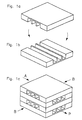
- Fig. 1 shows schematically the structure of an embodiment of the device according to the invention.
- Figures 1a and 1b there is one square film with rectangular cross-section grooves that run parallel to two sides of the square, shown.
- the two Foils are placed on top of one another, as indicated by the arrows.
- Fig. 1c is a stack of two basic units shown.
- the grooves form in each side surface of the stack Openings that are used as entry and exit openings.
- the continuous phase flows A from the rear into the device.
- the disperse phase B is fed in on the two perpendicular side surfaces.
- the Product P leaves the device at the front right.
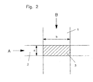
- a micro shear surface is shown schematically in FIG.
- the Grooves 1 for the disperse phase B cross the grooves 2 for the Continuous phase A.
- Fig. 3 shows different ways of switching the phases.
- the management of phases A (continuous phase) and B (disperse Phase) can be designed differently within the device become.
- the supply of A and B compared to FIG. 1 be interchanged (Fig. 3a).
- the supply of B does not need on both sides, but can also be done on one side (Fig. 3b).
- circuits can be shown in arrange in series in any way if for example a multiple dispersion of more than 2 phases is required.
- a serial connection several devices is also advantageous if for the duration of a parallel chemical reaction maintain a large phase interface should, d. H. irreversible phase separation by coalescence must be counteracted by redispersion.
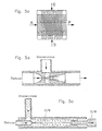
- Micro heat exchangers can provide volume-specific heat exchange performance of the individual heat exchangers to the respective local heat production can be adapted to the chemical reaction. As a rule, heat production increases along the reaction path from, so that the volume-specific heat exchange performance the micro heat exchanger z. B. by increasing the Microchannel dimensions can be reduced accordingly. from that result in significantly lower pressure losses at the Flow through the grooves. 4 are the continuous ones Phase again with A, the disperse phase with B and the cooling or heating means with D.
- the device according to the invention 4 is shown schematically on the left. Located on the right there is a micro heat exchanger 5 which is connected to the device 4 is separated by a distribution zone 6.
- paraffin oil W15 dynamic viscosity 15 mPas
- An emulsifier was added to the oil phase (HLB 11.5, 10% by mass on the oil phase).
- the emulsion is produced continuously, by separating paraffin oil and water from the disperser are fed.
- the volume flow ratio of Paraffin oil to water is 30:70.
- the emulsification process leads to an oil-in-water emulsion. Main goal of the investigations was minimizing that for emulsion making required energy expenditure.
- a microdisperser was used corresponding to Fig. 5a.
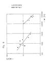
- the plot shows that to produce a particular medium droplet size when using a microdisperser significantly lower dynamic pressure losses (approx. factor 100) are required than with conventional apparatus.
Abstract
Description
Die Erfindung betrifft ein Verfahren und eine Vorrichtung zur
Herstellung eines dispersen Gemisches gemäß Anspruch 1 und Anspruch
2.The invention relates to a method and an apparatus for
Production of a disperse mixture according to
Dispergieren ist die Bezeichnung für die Zerteilung und möglichst feine Verteilung eines Stoffes in einem anderen. Die fertige Mischung heißt Dispersion. In einer Dispersion liegen eine oder mehrere dispers verteilte Phasen, die inneren Phasen, in einer kontinuierlichen Phase, der äußeren Phase, vor. Ist die disperse Phase vollständig in der kontinuierlichen Phase löslich, so geht die Dispersion sofort in eine homogene Mischung über. Typische Beispiele von durch Dispergieren hergestellten Dispersionen aus dem Bereich der chemischen Verfahrenstechnik sind
- Flüssigkeit-Flüssigkeit-Systeme:
- Emulsionen (disperse Phase: Flüssigkeit, kontinuierliche Phase: Flüssigkeit) ; Beispiele: Öl-in-Wasser-Emulsionen, Wasser-in-Öl-Emulsionen
- Gas-Flüssigkeit-Systeme:
- begaste Flüssigkeiten bzw. Schmelzen (disperse Phase: Gas,kontinuierliche Phase: Flüssigkeit), z. B. Schäume
- Nebel (disperse Phase: Flüssigkeit, kontinuierliche Phase: Gas)
- Flüssigkeit-Feststoff-Systeme:
- Suspensionen (disperse Phase: Feststoff, kontinuierliche Phase: Flüssigkeit), bei denen z. B. die Feststoffphase beim Dispergiervorgang durch Fällung eines übersättigt gelösten Stoffes entsteht.
- Liquid-liquid systems:
- Emulsions (disperse phase: liquid, continuous phase: liquid); Examples: oil-in-water emulsions, water-in-oil emulsions
- Gas-liquid systems:
- fumigated liquids or melts (disperse phase: gas, continuous phase: liquid), e.g. B. foams
- Mist (disperse phase: liquid, continuous phase: gas)
- Liquid-solid systems:
- Suspensions (disperse phase: solid, continuous phase: liquid), in which e.g. B. the solid phase is formed in the dispersing process by precipitation of a supersaturated solute.
Dispergieren ist der rein physikalische Vorgang des Zerteilens wie im Fall der Herstellung von Emulsionen; der Dispergiervorgang wird z. B. eingesetzt als einleitender Primärdispergierschritt oder als einer Primärdispergierung nachgeschalteter Redispergierschritt bei der Durchführung chemischer Reaktionen in zwei- und mehrphasigen Reaktionssystemen.Dispersing is the purely physical process of dividing as in the case of the production of emulsions; the dispersing process z. B. used as an initial primary dispersion step or as a primary dispersion downstream Redispersion step when carrying out chemical reactions in two- and multi-phase reaction systems.
Bei der Durchführung chemischer Reaktionen bestimmt das Verhältnis der Geschwindigkeit von Stofftransport zu Kinetik, inwieweit durch Intensivierung des Dispergiervorganges, d. h. durch Vergrößerung der Phasengrenzflächen zwischen den an der Reaktion beteiligten Phasen, der Reaktionsablauf beschleunigt werden kann . So ist bei sehr schnellen chemischen Reaktionen in der Regel der Stofftransport zwischen den an der Reaktion beteiligten Phasen für die Geschwindigkeit der chemischen Umsetzung und damit für die erzielbare Reaktorleistung maßgebend. Dementsprechend besteht eine wesentliche Aufgabe beim Dispergieren darin, möglichst viel Phasengrenzfläche pro Reaktionsvolumen zu erzeugen, d. h. möglichst kleine disperse Partikeln (z. B. Flüssigkeitstropfen, Gasblasen), und den dafür erforderlichen Energieaufwand zu minimieren.The ratio determines when chemical reactions are carried out the speed from mass transfer to kinetics, to what extent by intensifying the dispersing process, d. H. by increasing the phase interfaces between those at the Reaction phases involved, the reaction process accelerates can be . This is the case with very fast chemical reactions usually the mass transfer between those involved in the reaction phases involved for the rate of chemical conversion and thus decisive for the achievable reactor performance. Accordingly, there is an essential task in the Disperse in it as much phase interface as possible per reaction volume to generate, d. H. disperse particles as small as possible (e.g. liquid drops, gas bubbles), and the one for it to minimize required energy expenditure.
Technische Dispergierverfahren haben zum Ziel, eine oder mehrere Komponenten gleichmäßig und reproduzierbar in einer kontinuierlichen Phase zu zer- und verteilen. Zielgrößen sind dabei u. a. die reproduzierbare Herstellung von Dispersionen mit definierten Partikelgrößen für die disperse Phase, möglichst kleine Partikeln mit entsprechend großer volumenspezifischer Phasengrenzfläche zwischen disperser und kontinuierlicher Phase sowie enge Partikelgrößenverteilungen. Die zum Dispergieren eingesetzte Dispergiervorrichtung ist so zu gestalten und auszulegen, daß sie die Dispergieraufgabe mit minimalem Energieaufwand, d. h. mit hoher Effizienz, bewältigt.Technical dispersion processes have the goal of one or more Components evenly and reproducibly in a continuous To split and distribute the phase. Target sizes are included u. a. the reproducible production of dispersions with defined particle sizes for the disperse phase, if possible small particles with a correspondingly large volume-specific Phase interface between disperse and continuous Phase and narrow particle size distributions. The one to disperse The dispersing device used is to be designed in this way and interpret that they perform the dispersing task with minimal Energy expenditure, d. H. with high efficiency, mastered.
Gegenwärtig werden zum Dispergieren eine Vielzahl von Dispergierapparate eingesetzt. Prinzipiell zu unterscheiden sind dynamische und statische Dispergierapparate. A variety of dispersing apparatuses are currently used for dispersing used. A basic distinction must be made between dynamic ones and static dispersers.
Bei dynamischen Dispergierapparaten werden im allgemeinen sowohl die disperse Phase als auch die kontinuierliche Phase in Bewegung versetzt, wobei der Energieeintrag über die turbulente Strömungsenergie der bewegten Phasen erfolgt. Bei statischen Dispergierapparaten wird im allgemeinen nur die disperse Phase in Bewegung versetzt.In the case of dynamic dispersers, in general both the disperse phase and the continuous phase set in motion, the energy input via the turbulent Flow energy of the moving phases takes place. With static Dispersing apparatus is generally only the disperse Phase started.
Dynamische Dispergierapparate für Flüssigkeit-Flüssigkeit-Systeme sind z. B. Düsen, Düsen kombiniert mit nachgeschalteten Strahldispergatoren, Rührer sowie Rotor-Stator-Systeme, für Gas-Flüssigkeit-Systeme z. B. Injektoren bzw. Ejektoren, Venturidüsen und Rührer sowie für Flüssigkeit-Feststoff-Systeme z. B. Fälldüsen und Rührer.Dynamic dispersers for liquid-liquid systems are z. B. nozzles, nozzles combined with downstream Jet dispersers, stirrers and rotor-stator systems, for Gas-liquid systems e.g. B. injectors or ejectors, Venturi nozzles and stirrer as well as for liquid-solid systems z. B. precipitation nozzles and stirrers.
Statische Dispergierapparate für Flüssigkeit-Flüssigkeit-, Gas-Flüssigkeit- sowie Feststoff-Flüssigkeit-Systeme sind z. B. Einsteckrohre, Siebböden, Lochplatten aus Metall, Gummi oder Kunststoff, wahlweise auch mit pulsierender Platte, Rohrverteilerringe sowie Sinterplatten aus Glas oder Metall; Sinterplatten werden vorzugsweise für Gas-Flüssigkeit-Systeme eingesetzt.Static dispersers for liquid-liquid, There are gas-liquid and solid-liquid systems z. B. insert tubes, sieve plates, perforated plates made of metal, rubber or plastic, optionally also with a pulsating plate, pipe distributor rings and sintered plates made of glass or metal; sintered plates are preferred for gas-liquid systems used.
Nachteilig wirkt sich beim Einsatz der bekannten dynamischen Dispergierapparate aus, daß die Zerteilung der dispersen Phase in einem räumlich ausgedehnten turbulenten Scherfeld erfolgt, wobei die Ungleichverteilung der lokalen Energiedissipationsraten zu breiteren Partikelgrößenverteilungen für die disperse Phase führt. Zur Herstellung von Dispersionen mit geringen mittleren Partikelabmessungen für die disperse Phase und entsprechend großer volumenspezifischer Phasengrenzfläche ist ein vergleichsweise großer Energieaufwand erforderlich.The known dynamic has a disadvantageous effect Dispersers from that the dispersing of the disperse phase takes place in a spatially extensive turbulent shear field, taking the unequal distribution of local energy dissipation rates to wider particle size distributions for the disperse Phase leads. For the production of dispersions with low average particle dimensions for the disperse phase and accordingly large volume-specific phase interface is a comparatively large amount of energy required.
Derzeit verfügbare statische Dispergierapparate verhalten sich gegenüber dynamisch betriebenen Apparaten meist energetisch günstiger, d. h. das Verhältnis von erzeugter volumenspezifischer Phasengrenzfläche zu geleistetem Energieaufwand ist größer. Die mit statischen Apparaten absolut erzielbare volumenspezifische Phasengrenzfläche ist in der Regel jedoch klein.Static dispersers currently available behave usually energetically compared to dynamically operated devices cheaper, d. H. the ratio of generated volume-specific Phase interface to the energy expenditure is greater. The volume-specific that can be absolutely achieved with static devices However, phase interface is usually small.
Die DE 44 16 343 A1 beschreibt einen statischen Mikrovermischer, der aus einem Stapel von Folien zusammengesetzt ist. In die Folien sind auf einer Seite jeweils parallele Scharen schräger Kanäle eingearbeitet. Die Folien sind in der Weise gestapelt, daß die schrägen Kanäle in jeder zweiten Folie spiegelbildlich zu den Kanälen der beiden benachbarten Folien verlaufen. Die Nuten bilden zusammen mit der glatten Seite einer benachbarten Folie geschlossene Kanäle. Mit dem Mikrovermischer lassen sich Fluide miteinander vermischen. Die Vermischung erfolgt in der Weise, daß die schrägen Kanäle abwechselnd mit jeweils einem Fluid beaufschlagt werden. Beim Austritt der Fluide aus dem Mikrovermischer bilden sich feinste Fluid-Strahlen, die sich vollständig miteinander vermischen. Bei dem Mikrovermischer findet die Vermischung daher außerhalb der Vorrichtung statt.DE 44 16 343 A1 describes a static micromixer, which is composed of a stack of foils. In the foils are parallel shares on one side inclined channels incorporated. The slides are in the way that the slanted channels are stacked in every other slide mirror image of the channels of the two neighboring foils run. The grooves form one together with the smooth side adjacent slide closed channels. With the micro mixer fluids can be mixed together. The mixing takes place in such a way that the sloping channels alternate be charged with one fluid each. At the exit the fluids from the micromixer form the finest Fluid jets that mix completely with each other. With the micro-mixer, the mixing therefore takes place outside the device instead.
Gegenstand der DE 44 33 439 A1 ist ein Verfahren zur Durchführung chemischer Reaktionen mittels der Vorrichtung, die in der oben genannten DE 44 16 343 A1 beschrieben ist.DE 44 33 439 A1 relates to a method for implementation chemical reactions by means of the device used in the DE 44 16 343 A1 described above.
In der DE 39 26 466 A1 ist ein Mikroreaktor beschrieben, in dem die Vermischung von Fluiden innerhalb des Mikroreaktors erfolgen soll. Durch eine in einer Zwischenfolie befindliche querverlaufende Rille, die einen Mischraum bildet, werden zwei Reaktionspartner A und B in Teilströme aufgeteilt. Zwei Fluidströme werden in parallelen Mikrokanälen, die unmittelbar unterhalb bzw. oberhalb der Zwischenfolie verlaufen, geführt und sollen in der querverlaufenden Rille in der Zwischenfolie miteinander vermischt werden. Die Kanäle unterhalb der Zwischenfolie sind zu den Kanälen oberhalb der Zwischenfolie senkrecht angeordnet. Konstruktiv ergibt sich ein Folientriplett bestehend aus einer Folie für A, einer Zwischenfolie mit der querverlaufenden Rille und einer Folie für B. Dieses Triplett kann mehrfach aufeinandergestapelt werden. DE 39 26 466 A1 describes a microreactor in which is the mixing of fluids within the microreactor should be done. By one in an intermediate film transverse groove, which forms a mixing room, become two Reaction partners A and B divided into partial streams. Two fluid flows are in parallel microchannels that are just below or run above the intermediate film, guided and should be in the transverse groove in the intermediate film with each other be mixed. The channels below the intermediate film are perpendicular to the channels above the intermediate film arranged. Constructively, there is a film triplet consisting from a film for A, an intermediate film with the transverse Groove and a slide for B. This triplet can be stacked several times.
Beim bekannten Mikroreaktor strömen die noch unvermischten Fluide durch unterschiedlich lange Kanäle, bis sie auf die querverlaufenden Rillen treffen. Daraus resultiert zumindest eine unvollständige Vermischung innerhalb des Mikroreaktors. Außerdem soll jeweils ein Anteil beider Stoffströme die querverlaufende Rille passieren und innerhalb der Kanäle für den jeweils anderen Stoffstrom weitergeführt werden. Dies würde einen hohen Druckverlust in den betreffenden Anteilen verursachen, weshalb der bekannte Mikroreaktor ohne Modifikation der dargestellten Ausführungsformen nicht einsetzbar ist.In the known microreactor, the still unmixed flow Fluids through channels of different lengths until they reach the cross grooves. At least that results from that incomplete mixing within the microreactor. In addition, a proportion of both material flows should be the transverse one Groove pass and within the channels for the each other flow of material to be continued. This would cause a high pressure loss in the relevant parts, which is why the known microreactor without modification of illustrated embodiments can not be used.
Aus der WO-A-9630113 ist eine Vorrichtung zum Mischen kleiner Flüssigkeitsmengen bekannt, bei dem eine zu durchmischende Flüssigkeit in einen Einlaßkanal eintritt, hier auf mindestens zwei abzweigende, in einer Ebene liegende Mikrokanäle aufgeteilt wird, durch ein gegenüber der Ebene um 90° gedrehtes Zusammenflußelement wieder miteinander vereinigt und aus dem Zusammenflußelement in einen weiteren, in der Ebene liegenden Mikrokanal geleitet wird. Der weitere Mikrokanal kann den Einlaßkanal für eine weitere derartige Vorrichtung bilden. Die Vorrichtung enthält keine separaten Eintrittskanäle für die zu vermischenden Komponenten der Flüssigkeit.From WO-A-9630113 a mixing device is smaller Amounts of liquid known in which one to be mixed Liquid enters an inlet channel, here at least two branching micro-channels lying on one level are divided is, by a confluence element rotated by 90 ° with respect to the plane reunited with each other and out of the confluence element in another, lying in the plane Microchannel is routed. The further microchannel can be the inlet channel form for another such device. The The device contains no separate entry channels for the device mixing components of the liquid.
Der Erfindung liegt die Aufgabe zugrunde, ein Verfahren und eine Vorrichtung zur Herstellung eines dispersen Gemisches aus mindestens zwei Phasen vorzuschlagen, wobei das Gemisch innerhalb der Vorrichtung erzeugt wird. Bei der Dispergierung der Phasen soll sich ein geringerer Druckabfall einstellen.The invention has for its object a method and a device for producing a disperse mixture propose at least two phases, with the mixture within the device is generated. When dispersing the Phases should result in a lower pressure drop.
Die Aufgabe wird erfindungsgemäß durch das in Patentanspruch 1
beschriebene Verfahren und die in Patentanspruch 2 beschriebene
Vorrichtung gelöst. In den weiteren Patentansprüchen
sind bevorzugte Ausgestaltungen der Vorrichtung angegeben. The object is achieved by the in
Beim erfindungsgemäßen Verfahren werden sowohl die erste als auch die zweite Phase in vorzugsweise parallele Teilströme aufgeteilt. Die Teilströme der ersten Phase liegen in einer ersten und die Teilströme der zweiten Phase in einer zweiten ebenen Schicht. Innerhalb der jeweiligen ebenen Schichten werden die Teilströme der ersten Phase in einem Winkel in der Weise gegen die Teilströme der zweiten Phase geführt, daß der Dispergier- und Vermischungsvorgang ausgelöst wird. Die erste und die zweite ebene Schicht sind parallel zueinander angeordnet und grenzen unmittelbar aneinander.In the method according to the invention, both the first and also the second phase, preferably in parallel partial streams divided up. The partial flows of the first phase are in one first and the partial streams of the second phase in a second flat layer. Within the respective flat layers the partial flows of the first phase at an angle in the Way against the partial flows of the second phase that the Dispersing and mixing process is triggered. The first and the second flat layer are arranged parallel to each other and directly adjoin each other.
Die Dicke der ebenen Schichten kann weniger als 1000 µm, vorzugsweise weniger als 300 µm betragen. The thickness of the planar layers may be less than 1000 microns, preferably be less than 300 µm.
Die erfindungsgemäße Vorrichtung ist aus mindestens einer Grundeinheit aufgebaut. Die Grundeinheit besteht aus zwei Folien, in die jeweils auf einer Seite eine Schar paralleler Nuten eingebracht ist. Dies kann z. B. durch Fräsen mit einem Formdiamanten erfolgen, wie es z. B. in der DE 37 09 278 A1 beschrieben ist. Die Zahl der Nuten pro Folie kann prinzipiell unbegrenzt sein; vorzugsweise liegt sie im Bereich zwischen 2 und 300, wobei die Zahl der Nuten in den beiden Folien der Grundeinheiten nicht gleich zu sein braucht.The device according to the invention consists of at least one Basic unit built. The basic unit consists of two foils, a group of parallel grooves on each side is introduced. This can e.g. B. by milling with a Shape diamonds are made as it is e.g. B. in DE 37 09 278 A1 is described. In principle, the number of grooves per film can be be unlimited; it is preferably in the range between 2 and 300, the number of grooves in the two foils of the Basic units need not be the same.
Die Länge der Nuten in den Folien der erfindungsgemäßen Vorrichtung kann entsprechend dem jeweiligen Einsatzgebiet der Vorrichtung gewählt werden. Im allgemeinen liegen die Längen der Nuten zwischen 2 und 50 mm.The length of the grooves in the films of the device according to the invention can be used according to the respective application Device can be selected. Generally the lengths are of the grooves between 2 and 50 mm.
Prinzipiell kann der Querschnitt der Nuten nahezu beliebig, beispielsweise halbrund, dreieckig oder trapezförmig, sein. In einer bevorzugten Ausführungsform sind die Nuten jedoch im Querschnitt annähernd rechteckig. Die Nuten für beide Phasen sind vorzugsweise zwischen 10 und 1000 µm, besonders bevorzugt jedoch zwischen 10 und 300 µm breit und hoch. Vorteilhaft ist es, die Nuten für die disperse Phase möglichst kurz zu halten und innerhalb der angegebenen Bandbreite für die Nutabmessungen größer auszulegen als die Nuten für die kontinuierliche Phase. Die Stegbreite zwischen den Nuten liegt vorzugsweise zwischen 10 und 2000 µm, besonders bevorzugt zwischen 10 und 500 µm.In principle, the cross section of the grooves can be almost arbitrary, for example, semicircular, triangular or trapezoidal. In a preferred embodiment, the grooves are in Cross-section almost rectangular. The grooves for both phases are preferably between 10 and 1000 microns, particularly preferred however between 10 and 300 µm wide and high. It is advantageous it to keep the grooves for the disperse phase as short as possible and within the specified range for the groove dimensions to be larger than the grooves for the continuous Phase. The web width between the grooves is preferably between 10 and 2000 µm, particularly preferably between 10 and 500 µm.
Die beiden Folien werden in der Weise aufeinandergestapelt, daß die jeweils mit den Nuten versehenen Seiten der Folien aufeinander liegen und die Nuten der oberen und der unteren Folie miteinander einen Winkel, vorzugsweise einen rechten Winkel, miteinander einschließen.The two foils are stacked on top of one another in such a way that the sides of the foils provided with the grooves lie on top of each other and the grooves of the top and bottom Foil with each other an angle, preferably a right one Angle, enclose with each other.
Die Nuten erstrecken sich vorzugsweise über die gesamte Seite der Folien. Werden daher zwei Folien in der angegebenen Weise aufeinandergesetzt, erscheinen an den Seiten der Grundeinheit zwei Gruppen von Öffnungen, die dem Anfang und dem Ende jeder der beiden Scharen von Nuten entsprechen. Sind die Folien beispielsweise quadratisch und verlaufen die Nuten parallel zu zwei Kanten, wird beim Aufeinandersetzen der Folien in der Weise, daß die Nuten einen rechten Winkel miteinander einschließen, an jeder Seitenfläche der Grundeinheit eine Gruppe von Öffnungen sichtbar. Die Öffnungen an den Seitenflächen der Grundeinheit dienen als Ein- und Austrittsöffnungen für die Phasen bzw. für das disperse Gemisch. Da in der Regel nur eine Austrittsöffnung vorgesehen wird, können die verbleibenden drei Eintrittsöffnungen entsprechend dem vorgegebenen Dispergiervorgang verschaltet werden.The grooves preferably extend over the entire side of the slides. So be two slides in the way specified stacked on top, appear on the sides of the base unit two groups of openings, the beginning and the end of each of the two groups of grooves. Are the slides for example square and the grooves run parallel to two edges, when placing the foils in the Way that the grooves form a right angle with each other, a group on each side of the base unit visible from openings. The openings on the side surfaces of the Base unit serve as inlet and outlet openings for the Phases or for the disperse mixture. Since usually only one Exit opening is provided, the remaining can three inlet openings according to the specified dispersion process can be connected.
Für technische Dispergiervorgänge werden eine größere Zahl von Grundeinheiten, beispielsweise 50, aufeinandergestapelt. In diesem Fall werden die einander entsprechenden Öffnungen an den Seiten der Vorrichtung zu Ein- und Austrittsöffnungen zusammengeschaltet.For technical dispersing processes a larger number of Basic units, for example 50, stacked on top of one another. In in this case, the corresponding openings will appear the sides of the device interconnected to inlet and outlet openings.
Bei der erfindungsgemäßen Vorrichtung wird jede Phase in eine Vielzahl von Teilströmen aufgeteilt. Die Teilströme verschiedener Phasen werden in einem Winkel, etwa mit 90°, gegeneinander geführt, so daß sich die Teilströme im gemeinsamen Strömungsrandbereich berühren. Hier bilden sich Mikroscherflächen, an denen die disperse Phase umgelenkt und auf die kontinuierliche Phase verteilt wird.In the device according to the invention, each phase is divided into one Large number of sub-streams divided. The partial streams different Phases are at an angle to each other, for example at 90 ° led so that the partial flows in common Touch the flow edge area. Here micro-shear areas are formed, where the disperse phase is redirected and onto the continuous phase is distributed.
Aufgrund der lokal auf kleinstem Volumen wirkenden Scherkräfte treten im Bereich der Mikroscherflächen zwischen den beiden Phasen große volumenspezifische Energiedissipationsraten auf. Dabei werden Mikrovolumina aus dem einen Strom abgeschert und mit dem anderen Strom mitgerissen. Das den Dispergiervorgang auslösende Schergefälle zwischen der kontinuierlichen und der dispersen Phase ist bei den bevorzugten Abmessungen der Nuten von 10 bis 1000 µm und dem daraus resultierenden hohen Geschwindigkeitsgradienten extrem hoch. Due to the local shear forces acting on the smallest volume occur in the area of the micro shear surfaces between the two Phase up large volume-specific energy dissipation rates. Microvolumes are sheared from one stream and swept along with the other stream. That is the dispersing process triggering shear rate between the continuous and the disperse phase is in the preferred dimensions of the grooves from 10 to 1000 µm and the resulting high speed gradient extremely high.
Die Abmessungen der Mikroscherflächen ergeben sich aus den Breiten a und b der Nuten in den beiden Folien der Grundeinheit. Um den Vorteil, den die Mikrostrukturtechnik aufgrund der Abmessungen im Mikrometerbereich bietet, für Dispergierund Mischvorgänge effektiv nutzen zu können, sollten die Abmessungen der Mikroscherflächen vorzugsweise kleiner als 500 µm sein. Die auf kleinste Mikroschervolumina begrenzte spezifische Energiedissipationsrate ist hierbei größer als bei den bekannten Vorrichtungen.The dimensions of the micro shear surfaces result from the Widths a and b of the grooves in the two foils of the basic unit. The advantage that microstructure technology offers which offers dimensions in the micrometer range for dispersing and To be able to use mixing processes effectively, the dimensions should be the micro shear areas are preferably less than 500 µm. The specific one limited to the smallest micro shear volumes The energy dissipation rate is greater than that of the known devices.
In dem Fall, daß die beiden Phasen chemisch nicht miteinander reagieren und auch nicht ineinander löslich sind, wird nun aufgrund der Verteilung der Phasen auf eine große Zahl von Teilströmen eine feine Verteilung der dispersen in der kontinuierlichen Phase erzeugt. In dem Fall, daß die beiden Phasen zusätzlich chemisch miteinander reagieren, hat man durch die feine Verteilung der dispersen Phase in der kontinuierlichen Phase optimale Startbedingungen für den Ablauf der chemischen Reaktion geschaffen.In the event that the two phases are not chemically linked react and are not soluble in each other, will now due to the distribution of the phases over a large number of Partial flows a fine distribution of the disperse in the continuous Phase generated. In the event that the two phases additionally react chemically with one another through the fine distribution of the disperse phase in the continuous Phase optimal starting conditions for the course of the chemical Reaction created.
Die erfindungsgemäße Vorrichtung ist sowohl für Kleinstmengen als auch für technische Durchsätze einsetzbar. Durch Variation der Anzahl der Mikrokanäle können in einem cm3 des Mikrodispergierapparates einige wenige bis mehrere zehntausend Mikroscherflächen untergebracht werden.The device according to the invention can be used both for very small quantities and for technical throughputs. By varying the number of microchannels, a few to several tens of thousands of microshear surfaces can be accommodated in one cm 3 of the microdispersion apparatus.
Weitere Vorteile sind die Verbesserung der Ausbeute, der Selektivität und der Produktqualität bei den in der erfindungsgemäßen Vorrichtung durchgeführten chemischen Reaktionen. Mit der Vorrichtung lassen sich wegen der Einstellbarkeit der Partikelgrößenverteilungen Produkte mit neuen Eigenschaftsprofilen gewinnen. Ein weiterer Vorteil ist in den sehr geringen inneren Abmessungen der Vorrichtung zu sehen, da sich damit der Aufwand für die Sicherheit und der Betriebsinhalt der Vorrichtung stark vermindern lassen. Bei nachgeschalteten Mikrowärmetauschern kann Wärme effizient abgeleitet werden. Further advantages are the improvement of the yield, the selectivity and the product quality in those in the invention Device chemical reactions performed. With the device can be because of the adjustability of the Particle size distributions Products with new property profiles win. Another advantage is the very low internal dimensions of the device can be seen, since it the effort for security and the operational content of the Have the device greatly reduced. With downstream micro heat exchangers heat can be dissipated efficiently.
Neben der effizienten Wärmeabfuhr hat die Einleitung eines zwei- oder mehrphasigen Gemisches in die Mikrokanäle eines angeschlossenen Mikrowärmetauschers den Vorteil, daß aufgrund der geringen Kanalabmessungen große Geschwindigkeitsgradienten und damit große Scherkräfte auftreten, die zu einer Unterdrückung der Koaleszenz sowie zu einer Vergleichmäßigung des Partikelgrößenspektrums führen können.In addition to the efficient heat dissipation, the initiation of a two-phase or multi-phase mixture in the microchannels of a connected Micro heat exchanger has the advantage that the small channel dimensions, large speed gradients and thus large shear forces occur which lead to suppression of coalescence and to make the Particle size spectrum can lead.
Als bevorzugte Anwendungsfelder für die Vorrichtung sind zu nennen die Herstellung von Emulsionen in Flüssigkeit-Flüssigkeit-Systemen, darüber hinaus die Herstellung von Dispersionen wie z. B. begaste Flüssigkeiten, Schäume, Nebel und Suspensionen (aus Fällprozessen). An den eigentlichen Dispergierprozeß kann sich dabei eine chemische Reaktion anschließen. Weitere Anwendungsfelder sind das Homogenisieren von Dispersionen mit dem Ziel der Einstellung engerer Partikelgrößenverteilungen, das Redispergieren von Dispersionen, um einer Phasentrennung, z. B. durch Koaleszenz, entgegenzuwirken sowie das homogene Mischen von Flüssigkeiten bzw. Gasen.The preferred fields of application for the device are name the production of emulsions in liquid-liquid systems, also the production of dispersions such as B. fumigated liquids, foams, mists and suspensions (from precipitation processes). The actual dispersion process a chemical reaction can follow. Further Fields of application are the homogenization of dispersions with the goal of setting narrower particle size distributions, the redispersion of dispersions to achieve phase separation, z. B. to counteract by coalescence and the homogeneous Mixing liquids or gases.
Die Erfindung wird im folgenden anhand von Figuren näher erläutert.
Es zeigen
Fig. 1 zeigt schematisch den Aufbau einer Ausführungsform der erfindungsgemäßen Vorrichtung. In Fig. 1a und 1b ist jeweils eine quadratische Folie mit im Querschnitt rechteckigen Nuten, die parallel zu zwei Quadratseiten verlaufen, dargestellt. Die beiden Folien werden, wie durch die Pfeile angedeutet, aufeinandergesetzt. In Fig. 1c ist ein Stapel von zwei Grundeinheiten dargestellt. Die Nuten bilden in jeder Seitenfläche des Stapels Öffnungen, die als Ein- und Austrittsöffnungen genutzt werden. In der dargestellten Ausführungsform strömt die kontinuierliche Phase A von der Rückseite aus in die Vorrichtung. Die disperse Phase B wird an den beiden dazu senkrechten Seitenflächen eingespeist. Das Produkt P verläßt die Vorrichtung vorne rechts.Fig. 1 shows schematically the structure of an embodiment of the device according to the invention. In Figures 1a and 1b there is one square film with rectangular cross-section grooves that run parallel to two sides of the square, shown. The two Foils are placed on top of one another, as indicated by the arrows. In Fig. 1c is a stack of two basic units shown. The grooves form in each side surface of the stack Openings that are used as entry and exit openings. In In the illustrated embodiment, the continuous phase flows A from the rear into the device. The disperse phase B is fed in on the two perpendicular side surfaces. The Product P leaves the device at the front right.
In Fig. 2 ist eine Mikroscherfläche schematisch dargestellt. Die
Nuten 1 für die disperse Phase B kreuzen die Nuten 2 für die
kontinuierliche Phase A. An der Kreuzungsstelle bildet sich die
Mikroscherfläche 3, deren Größe durch die Breiten a und b der
beiden Nuten gegeben ist.A micro shear surface is shown schematically in FIG. The
Fig. 3 zeigt verschiedene Möglichkeiten der Schaltung der Phasen. Die Führung der Phasen A (kontinuierliche Phase) und B (disperse Phase) kann innerhalb der Vorrichtung unterschiedlich gestaltet werden. So kann die Zuführung von A und B gegenüber Fig. 1 vertauscht sein (Fig. 3a). Die Zuführung von B braucht nicht beidseitig, sondern kann auch einseitig erfolgen (Fig. 3b). Die in Fig. 3a und 3b dargestellten Verschaltungen lassen sich in beliebiger Weise seriell hintereinander anordnen, wenn beispielsweise eine Mehrfachdispergierung von mehr als 2 Phasen erforderlich ist. Eine serielle Verschaltung mehrerer Vorrichtungen ist auch dann vorteilhaft, wenn für die Dauer einer parallel ablaufenden chemischen Reaktion eine große Phasengrenzfläche aufrechterhalten werden soll, d. h. einer irreversiblen Phasentrennung durch Koaleszenz mittels Redispergierung entgegengewirkt werden muß.Fig. 3 shows different ways of switching the phases. The management of phases A (continuous phase) and B (disperse Phase) can be designed differently within the device become. For example, the supply of A and B compared to FIG. 1 be interchanged (Fig. 3a). The supply of B does not need on both sides, but can also be done on one side (Fig. 3b). In the 3a and 3b circuits can be shown in arrange in series in any way if for example a multiple dispersion of more than 2 phases is required. A serial connection several devices is also advantageous if for the duration of a parallel chemical reaction maintain a large phase interface should, d. H. irreversible phase separation by coalescence must be counteracted by redispersion.
Bei stark exotherm oder endotherm ablaufenden Reaktionen empfiehlt
sich die Nachschaltung eines oder mehrerer seriell angeordneter
Mikrowärmeübertrager entsprechend Fig. 4. Dafür geeignete
Mikrowärmeübertrager sind in der DE 37 09 278 A1 beschrieben.
Bei mehreren seriell hintereinander verschalteten
Mikrowärmeübertragern kann die volumenspezifische Wärmeaustauschleistung
der einzelnen Wärmeübertrager an die jeweilige
lokale Wärmeproduktion der chemischen Reaktion angepaßt werden.
In der Regel nimmt die Wärmeproduktion längs des Reaktionswegs
ab, so daß die volumenspezifische Wärmeaustauschleistung
der Mikrowärmetauscher z. B. durch Vergrößern der
Mikrokanalabmessungen entsprechend reduziert werden kann. Daraus
resultieren deutlich geringere Druckverluste bei der
Durchströmung der Nuten. In Fig. 4 sind die kontinuierliche
Phase wiederum mit A, die disperse Phase mit B und das Kühl-
oder Heizmittel mit D bezeichnet. Die erfindungsgemäße Vorrichtung
4 ist schematisch links dargestellt. Rechts befindet
sich ein Mikrowärmeübertrager 5, der von der Vorrichtung 4
durch eine Verteilungszone 6 getrennt ist.Recommended for highly exothermic or endothermic reactions
the subsequent connection of one or more serially arranged
Micro heat exchanger according to Fig. 4. Suitable for this
Micro heat exchangers are described in DE 37 09 278 A1.
If several are connected in series
Micro heat exchangers can provide volume-specific heat exchange performance
of the individual heat exchangers to the respective
local heat production can be adapted to the chemical reaction.
As a rule, heat production increases along the reaction path
from, so that the volume-specific heat exchange performance
the micro heat exchanger z. B. by increasing the
Microchannel dimensions can be reduced accordingly. from that
result in significantly lower pressure losses at the
Flow through the grooves. 4 are the continuous ones
Phase again with A, the disperse phase with B and the cooling
or heating means with D. The device according to the invention
4 is shown schematically on the left. Located on the right
there is a
Die Erfindung wird im folgenden anhand eines Beispiels näher erläutert.The invention will be explained in more detail below using an example explained.
Zur Beurteilung des Dispergierverhaltens des Mikrodispergierapparates bei Flüssigkeit-Flüssigkeit-Systemen wird Paraffinöl W15 (dynamische Viskosität 15 mPas) mit destilliertem Wasser bei 20 °C emulgiert. Zur Stabilisierung der Emulsion wird der Ölphase ein Emulgator zugesetzt (HLB 11.5, 10 Ma.-% bezogen auf die Ölphase). Die Herstellung der Emulsion erfolgt kontinuierlich, indem Paraffinöl und Wasser getrennt dem Dispergierapparat zugeführt werden. Das Volumenstromverhältnis von Paraffinöl zu Wasser beträgt 30 : 70. Der Emulgierprozeß führt zu einer Öl-in-Wasser-Emulsion. Hauptziel der Untersuchungen war die Minimierung des für die Emulsionsherstellung erforderlichen Energieaufwandes. Eingesetzt wurde ein Mikrodispergierapparat entsprechend Fig. 5a.To assess the dispersing behavior of the microdispersing device in liquid-liquid systems, paraffin oil W15 (dynamic viscosity 15 mPas) with distilled water emulsified at 20 ° C. To stabilize the emulsion, the An emulsifier was added to the oil phase (HLB 11.5, 10% by mass on the oil phase). The emulsion is produced continuously, by separating paraffin oil and water from the disperser are fed. The volume flow ratio of Paraffin oil to water is 30:70. The emulsification process leads to an oil-in-water emulsion. Main goal of the investigations was minimizing that for emulsion making required energy expenditure. A microdisperser was used corresponding to Fig. 5a.
Der eingesetzte Mikrodispergierapparat weist folgende Spezifikationen auf:
- Passage A:
33 Metallfolien mit jeweils 77 Mikrokanälen, also insgesamt 2541 Mikrokanäle;Kanalbreite 100 µm, Kanalhöhe 70 µm, Kanallänge 14 mm, Stegbreite zwischen zwei parallelen Mikrokanälen 30 µm - Passage B:
33 Metallfolien mit jeweils 39 parallelen Mikrokanälen, also insgesamt 1287 Mikrokanäle; Kanalbreite 200 µm, Kanalhöhe 140 µm, Kanallänge 14 mm, Stegbreite zwischen zwei parallelen Mikrokanälen 60 µm - Anzahl der Mikroscherflächen: 99099
- aktives Bauteilvolumen: 1 cm3
- Werkstoff: Edelstahl 1.4301.
- Passage A:
33 metal foils with 77 microchannels each, for a total of 2541 microchannels;Channel width 100 µm, channel height 70 µm, channel length 14 mm, web width between two parallel microchannels 30 µm - Passage B:
33 metal foils with 39 parallel microchannels each, for a total of 1287 microchannels; Channel width 200 µm, channel height 140 µm, channel length 14 mm, web width between two parallel microchannels 60 µm - Number of micro shear areas: 99099
- active component volume: 1 cm 3
- Material: stainless steel 1.4301.
Um die Leistungsfähigkeit des Mikrodispergierapparates beurteilen zu können, wurden unter gleichen Versuchsbedingungen Emulsionen mittels zweistufiger Düsen (Fig. 5b) bzw. mit einer einstufigen Düse mit nachgeschaltetem Strahldispergator (Fig. 5c) hergestellt.To assess the performance of the microdisperser to be able to, were under the same experimental conditions Emulsions using two-stage nozzles (Fig. 5b) or with a single-stage nozzle with downstream jet disperser (Fig. 5c).
In den Versuchen 1 bis 4 wurden verschiedene Strömungsführungsvarianten unter Einsatz des Mikrodispergierapparates getestet (Fig. 6):
- Versuch V1: Ölzulauf beidseitig über Passage B, Wasserzulauf einseitig über Passage A
- Versuch V2: Wasserzulauf beidseitig über B, Ölzulauf einseitig über A
- Versuch V3: Ölzulauf beidseitig über A, Wasserzulauf einseitig über B
- Versuch V4: Wasserzulauf beidseitig über A, Ölzulauf einseitig über B
- Experiment V1: Oil inlet on both sides via passage B, water inlet on one side via passage A
- Test V2: water inlet on both sides via B, oil inlet on one side via A
- Experiment V3: oil supply on both sides via A, water supply on one side via B
- Experiment V4: water inlet on both sides via A, oil inlet on one side via B
In den Versuchen 5 bis 7 wurden unterschiedliche konventionelle Düsen getestet:
- Versuch V5: zweistufige Düse,
Durchmesser 1. Düse: 0.3 mm, Durchm. 2. Düse: 0,4 mm - Versuch V6: zweistufige Düse,
Durchmesser 1. Düse: 0,6 mm, Durchm. 2. Düse: 1,1 mm - Versuch V7: einstufige Düse mit nachgeschaltetem Strahldispergator,
Düsendurchmesser Strahldispergator mit zwei 0,8 mm-Bohrungen auf dem Umfang:
- Test V5: two-stage nozzle, diameter of the 1st nozzle: 0.3 mm, diam. 2. Nozzle: 0.4 mm
- Test V6: two-stage nozzle, diameter of the 1st nozzle: 0.6 mm, diam. 2. Nozzle: 1.1 mm
- Test V7: single-stage nozzle with downstream jet disperser, nozzle diameter 0.6 mm, jet disperser with two 0.8 mm holes on the circumference:
In Fig. 6 ist der mittels Lichtbeugung ermittelte Medianwert
der Tropfengröße (Dimension µm) über dem für den Emulgiervorgang
signifikanten mittleren dynamischen Druckverlust Pm (Dimension
Pa) aufgetragen. Die in den Mikrokanälen des Mikrodispergierapparates
auftretende Wandreibung bleibt dabei unberücksichtigt.
Der mittlere dynamische Druckverlust ergibt sich
durch Mittelung über die Volumenströme des Fluids A und B entsprechend
Die Auftragung zeigt, daß zur Herstellung einer bestimmten mittleren Tropfengröße bei Einsatz eines Mikrodispergierapparates deutlich geringere dynamische Druckverluste (ca. Faktor 100) erforderlich sind als bei konventionellen Apparaten.The plot shows that to produce a particular medium droplet size when using a microdisperser significantly lower dynamic pressure losses (approx. factor 100) are required than with conventional apparatus.
Claims (6)
- Method of producing a dispersed mixture with at least one first phase and one second phase, whereina) both the first phase and the second phase are divided into split streams, so thatb) the split streams of the first phase lie in a first flat layer, and the split streams of the second phase lie in a second flat layer, andc) the split streams of the first phase in the first flat layer are supplied at an angle to the split streams in the second flat layer to start a dispersing and mixing process,d) the split streams being combined and mixed at locations where the split streams of the first phase intersect the split streams of the second phase, ande) the flat layers being disposed parallel to, and directly above, each other.
- Apparatus for producing a dispersed mixture from at least one first phase and one second phase, said apparatus comprisingthe two foils being combined in the basic unit in such a manner thatat least one basic unit which includestwo foils,which each have a number of parallel grooves on one side of the foils,the sides of the two foils provided with grooves lie one on top of the other, andform an angle with each other.
- Apparatus according to claim 2, having an angle of 90°.
- Apparatus according to claim 3, having rectangular foils, wherein the grooves extend parallel to two edges of the foils.
- Apparatus according to one of claims 2 to 4, having grooves which have a width and depth between 10 and 1000 µm.
- Apparatus according to one of claims 2 to 5, having a micro-heat exchanger connected downstream of the product outlet section of the apparatus.
Applications Claiming Priority (3)
| Application Number | Priority Date | Filing Date | Title |
|---|---|---|---|
| DE19703779A DE19703779C2 (en) | 1997-02-01 | 1997-02-01 | Method and device for producing a disperse mixture |
| DE19703779 | 1997-02-01 | ||
| PCT/EP1998/000217 WO1998033582A1 (en) | 1997-02-01 | 1998-01-16 | Method and device for producing a dispersed mixture |
Publications (2)
| Publication Number | Publication Date |
|---|---|
| EP0956151A1 EP0956151A1 (en) | 1999-11-17 |
| EP0956151B1 true EP0956151B1 (en) | 2003-03-12 |
Family
ID=7819023
Family Applications (1)
| Application Number | Title | Priority Date | Filing Date |
|---|---|---|---|
| EP98905302A Expired - Lifetime EP0956151B1 (en) | 1997-02-01 | 1998-01-16 | Method and device for producing a dispersed mixture |
Country Status (6)
| Country | Link |
|---|---|
| US (1) | US6305834B1 (en) |
| EP (1) | EP0956151B1 (en) |
| JP (1) | JP3188479B2 (en) |
| AT (1) | ATE234143T1 (en) |
| DE (2) | DE19703779C2 (en) |
| WO (1) | WO1998033582A1 (en) |
Families Citing this family (63)
| Publication number | Priority date | Publication date | Assignee | Title |
|---|---|---|---|---|
| DE19741645A1 (en) * | 1997-09-22 | 1999-03-25 | Bayer Ag | Method and device for the oxidation of organic compounds in the liquid phase using peroxidic oxidizing agents |
| DE29903296U1 (en) * | 1999-02-24 | 2000-08-03 | Cpc Cellular Process Chemistry | Microreactor |
| DE19917156B4 (en) * | 1999-04-16 | 2006-01-19 | INSTITUT FüR MIKROTECHNIK MAINZ GMBH | Process for the preparation of a water-in-diesel oil emulsion as fuel and its uses |
| DE19927556C2 (en) * | 1999-06-16 | 2003-05-08 | Inst Mikrotechnik Mainz Gmbh | Static micromixer and method for statically mixing two or more starting materials |
| US7713279B2 (en) | 2000-12-20 | 2010-05-11 | Fox Hollow Technologies, Inc. | Method and devices for cutting tissue |
| US8328829B2 (en) | 1999-08-19 | 2012-12-11 | Covidien Lp | High capacity debulking catheter with razor edge cutting window |
| US7887556B2 (en) | 2000-12-20 | 2011-02-15 | Fox Hollow Technologies, Inc. | Debulking catheters and methods |
| US6299622B1 (en) | 1999-08-19 | 2001-10-09 | Fox Hollow Technologies, Inc. | Atherectomy catheter with aligned imager |
| US7708749B2 (en) | 2000-12-20 | 2010-05-04 | Fox Hollow Technologies, Inc. | Debulking catheters and methods |
| DE10009935C2 (en) * | 2000-03-02 | 2003-12-11 | Karlsruhe Forschzent | Process for anodizing the inner surfaces of a capillary-like cavity |
| WO2002022296A2 (en) * | 2000-09-11 | 2002-03-21 | Allison Advanced Development Company | Mechanically grooved sheet and method of manufacture |
| DE10055374B4 (en) * | 2000-11-08 | 2006-03-02 | Bartels Mikrotechnik Gmbh | Distributor plate for liquids and gases |
| ES2436668T3 (en) | 2000-12-20 | 2014-01-03 | Covidien Lp | Catheter to remove atheromatous or thrombotic occlusive material |
| US6727203B2 (en) | 2001-03-28 | 2004-04-27 | Fuji Photo Film Co., Ltd. | Method for producing microcapsules and heat-sensitive recording material |
| DK1392419T3 (en) * | 2001-05-17 | 2012-03-12 | Amalgamated Res Inc | Fractal device for mixing and reactor applications |
| US6805846B2 (en) * | 2001-06-18 | 2004-10-19 | Honda Giken Kogyo Kabushiki Kaisha | Compact reactor capable of being charged with catalytic material for use in a hydrogen generation/fuel cell system |
| DE10219523A1 (en) * | 2002-05-02 | 2003-11-13 | Wella Ag | Process for the technical production of hair or skin cosmetic products using equipment with microstructure units |
| DE10317451A1 (en) * | 2003-04-16 | 2004-11-18 | Degussa Ag | Reactor for heterogeneously catalyzed reactions |
| US8246640B2 (en) | 2003-04-22 | 2012-08-21 | Tyco Healthcare Group Lp | Methods and devices for cutting tissue at a vascular location |
| JP2005068125A (en) * | 2003-08-21 | 2005-03-17 | Rohm & Haas Co | Method for preparing biocide-blended material |
| JP4025735B2 (en) * | 2003-08-21 | 2007-12-26 | ローム アンド ハース カンパニー | Method for treating aqueous systems |
| EP1804964A1 (en) * | 2004-10-01 | 2007-07-11 | Velocys Inc. | Multiphase mixing process using microchannel process technology |
| CN101132854B (en) * | 2004-11-16 | 2011-07-06 | 万罗赛斯公司 | Multiphase reaction process using microchannel technology |
| WO2006057895A2 (en) * | 2004-11-17 | 2006-06-01 | Velocys Inc. | Process for making or treating an emulsion using microchannel technology |
| KR100695151B1 (en) * | 2005-05-18 | 2007-03-14 | 삼성전자주식회사 | Fluid mixing device using cross channels |
| US8048383B2 (en) * | 2006-04-20 | 2011-11-01 | Velocys, Inc. | Process for treating and/or forming a non-Newtonian fluid using microchannel process technology |
| US20070276419A1 (en) | 2006-05-26 | 2007-11-29 | Fox Hollow Technologies, Inc. | Methods and devices for rotating an active element and an energy emitter on a catheter |
| JP4968896B2 (en) * | 2006-09-27 | 2012-07-04 | 富士フイルム株式会社 | Dispersion manufacturing apparatus and dispersion manufacturing method |
| DE102007041737B4 (en) * | 2007-09-04 | 2010-01-14 | Buma Gmbh & Co. Kg | Mixing device for mixing viscous components |
| JP5468271B2 (en) * | 2008-02-08 | 2014-04-09 | 花王株式会社 | Method for producing fine particle dispersion |
| US8784440B2 (en) | 2008-02-25 | 2014-07-22 | Covidien Lp | Methods and devices for cutting tissue |
| US8246241B2 (en) * | 2008-06-18 | 2012-08-21 | Actamax Surgical Materials, Llc | Mixing device having a corrugated conveying plate |
| AU2009303501B2 (en) | 2008-10-13 | 2013-11-21 | Covidien Lp | Devices and methods for manipulating a catheter shaft |
| US20110146226A1 (en) * | 2008-12-31 | 2011-06-23 | Frontline Aerospace, Inc. | Recuperator for gas turbine engines |
| RU2509537C2 (en) | 2009-04-29 | 2014-03-20 | ТАЙКО ХЕЛСКЕА ГРУП эЛПи | Methods and devices for tissue cutting and cleansing |
| CN102458276B (en) | 2009-05-14 | 2014-05-21 | 泰科保健集团有限合伙公司 | Easily cleaned atherectomy catheters and methods of use |
| JP5487423B2 (en) * | 2009-07-14 | 2014-05-07 | 株式会社神戸製鋼所 | Heat exchanger |
| JP5740548B2 (en) * | 2009-08-04 | 2015-06-24 | ソレニス・テクノロジーズ・ケイマン・エル・ピー | Apparatus, system, and method for emulsifying oil and water |
| US9138696B2 (en) | 2009-11-30 | 2015-09-22 | Corning Incorporated | Honeycomb body u-bend mixers |
| CN104490454A (en) | 2009-12-02 | 2015-04-08 | 泰科保健集团有限合伙公司 | Methods And Devices For Cutting Tissue |
| CA2783301C (en) | 2009-12-11 | 2015-02-24 | Tyco Healthcare Group Lp | Material removal device having improved material capture efficiency and methods of use |
| US8757444B2 (en) | 2009-12-17 | 2014-06-24 | Actamax Surgical Materials, Llc | Dispensing device having an array of laterally spaced tubes |
| JP2011147932A (en) * | 2009-12-24 | 2011-08-04 | Kao Corp | Fluid-mixing device |
| US9415357B2 (en) | 2010-02-28 | 2016-08-16 | Corning Incorporated | Honeycomb body interdigitated mixers and methods for producing |
| EP2579791B1 (en) | 2010-06-14 | 2014-04-23 | Covidien LP | Material removal device |
| DE102010041282A1 (en) * | 2010-09-23 | 2012-03-29 | Behr Gmbh & Co. Kg | Mixing element and mixing module for two air streams crossing in an air conditioner |
| JP5642488B2 (en) * | 2010-10-04 | 2014-12-17 | 株式会社神戸製鋼所 | Channel structure |
| JP5636114B2 (en) | 2010-10-28 | 2014-12-03 | コヴィディエン リミテッド パートナーシップ | Substance removal device and method of use |
| KR101518151B1 (en) | 2010-11-11 | 2015-05-06 | 코비디엔 엘피 | Flexible debulking catheters with imaging and methods of use and manufacture |
| JP2012120962A (en) * | 2010-12-07 | 2012-06-28 | Kobe Steel Ltd | Flow channel structure |
| US20120261104A1 (en) * | 2011-04-12 | 2012-10-18 | Altex Technologies Corporation | Microchannel Heat Exchangers and Reactors |
| JP5806407B2 (en) | 2011-09-01 | 2015-11-10 | コヴィディエン リミテッド パートナーシップ | Catheter with helical drive shaft and manufacturing method |
| US9532844B2 (en) | 2012-09-13 | 2017-01-03 | Covidien Lp | Cleaning device for medical instrument and method of use |
| US9943329B2 (en) | 2012-11-08 | 2018-04-17 | Covidien Lp | Tissue-removing catheter with rotatable cutter |
| WO2015200702A1 (en) | 2014-06-27 | 2015-12-30 | Covidien Lp | Cleaning device for catheter and catheter including the same |
| US10161690B2 (en) * | 2014-09-22 | 2018-12-25 | Hamilton Sundstrand Space Systems International, Inc. | Multi-layer heat exchanger and method of distributing flow within a fluid layer of a multi-layer heat exchanger |
| US10314667B2 (en) | 2015-03-25 | 2019-06-11 | Covidien Lp | Cleaning device for cleaning medical instrument |
| JP6069801B2 (en) * | 2015-06-24 | 2017-02-01 | 利春 森園 | Ladder left and right side swing prevention auxiliary prop |
| US10292721B2 (en) | 2015-07-20 | 2019-05-21 | Covidien Lp | Tissue-removing catheter including movable distal tip |
| US10314664B2 (en) | 2015-10-07 | 2019-06-11 | Covidien Lp | Tissue-removing catheter and tissue-removing element with depth stop |
| EP3599441B1 (en) | 2018-07-25 | 2023-04-26 | GF Machining Solutions AG | Regeneration device for regenerating a coolant dispersion |
| CN110090607A (en) * | 2019-05-16 | 2019-08-06 | 青岛三易安化工设备有限公司 | A kind of microreactor |
| WO2023051796A1 (en) * | 2021-09-30 | 2023-04-06 | 上海弼领生物技术有限公司 | Production system and method for producing nanoparticles |
Family Cites Families (15)
| Publication number | Priority date | Publication date | Assignee | Title |
|---|---|---|---|---|
| DD128156A1 (en) * | 1976-09-22 | 1977-11-02 | Christian Merkel | DEVICE FOR MIXING STROEMENDER MEDIA |
| SE418646B (en) * | 1976-09-29 | 1981-06-15 | Svenska Flaektfabriken Ab | CONTACT BODY FOR LIQUID AND GAS |
| US4222671A (en) * | 1978-09-05 | 1980-09-16 | Gilmore Oscar Patrick | Static mixer |
| SE432059B (en) * | 1980-04-11 | 1984-03-19 | Munters Ab Carl | MIXING DEVICE FOR MIXING OF FLOWING MEDIA INCLUDING AT LEAST TWO SYSTEMS OF SEPARATED FLOW CHANNELS |
| JPS5787820A (en) * | 1980-11-20 | 1982-06-01 | Teijin Ltd | Stationary element for mixing fluid |
| DE3709278A1 (en) * | 1987-03-20 | 1988-09-29 | Kernforschungsz Karlsruhe | METHOD FOR PRODUCING FINE-STRUCTURED BODIES |
| DE3926466C2 (en) * | 1989-08-10 | 1996-12-19 | Christoph Dipl Ing Caesar | Microreactor for carrying out chemical reactions of two chemical substances with strong heat |
| US5094788A (en) * | 1990-12-21 | 1992-03-10 | The Dow Chemical Company | Interfacial surface generator |
| US5137369A (en) * | 1991-01-18 | 1992-08-11 | Hodan John A | Static mixing device |
| DE4416343C2 (en) * | 1994-05-09 | 1996-10-17 | Karlsruhe Forschzent | Static micro mixer |
| DE59503529D1 (en) | 1994-05-09 | 1998-10-15 | Bayer Ag | METHOD AND DEVICE FOR CARRYING OUT CHEMICAL REACTIONS BY MEANS OF MICROSTRUCTURE MIXTURE |
| DE4433439A1 (en) * | 1994-09-20 | 1996-03-21 | Kernforschungsz Karlsruhe | Mixing fluids using adjacent micro structures generating diffusion or turbulence |
| US5531831A (en) * | 1994-12-12 | 1996-07-02 | Minnesota Mining And Manufacturing Company | Static blending device |
| DE19511603A1 (en) | 1995-03-30 | 1996-10-02 | Norbert Dr Ing Schwesinger | Device for mixing small amounts of liquid |
| DE19540292C1 (en) * | 1995-10-28 | 1997-01-30 | Karlsruhe Forschzent | Static micromixer |
-
1997
- 1997-02-01 DE DE19703779A patent/DE19703779C2/en not_active Expired - Fee Related
-
1998
- 1998-01-16 DE DE59807470T patent/DE59807470D1/en not_active Expired - Lifetime
- 1998-01-16 JP JP53249098A patent/JP3188479B2/en not_active Expired - Fee Related
- 1998-01-16 AT AT98905302T patent/ATE234143T1/en not_active IP Right Cessation
- 1998-01-16 US US09/355,638 patent/US6305834B1/en not_active Expired - Lifetime
- 1998-01-16 WO PCT/EP1998/000217 patent/WO1998033582A1/en active IP Right Grant
- 1998-01-16 EP EP98905302A patent/EP0956151B1/en not_active Expired - Lifetime
Also Published As
| Publication number | Publication date |
|---|---|
| EP0956151A1 (en) | 1999-11-17 |
| JP2000509330A (en) | 2000-07-25 |
| ATE234143T1 (en) | 2003-03-15 |
| DE59807470D1 (en) | 2003-04-17 |
| US6305834B1 (en) | 2001-10-23 |
| WO1998033582A1 (en) | 1998-08-06 |
| JP3188479B2 (en) | 2001-07-16 |
| DE19703779C2 (en) | 2003-06-05 |
| DE19703779A1 (en) | 1998-08-13 |
Similar Documents
| Publication | Publication Date | Title |
|---|---|---|
| EP0956151B1 (en) | Method and device for producing a dispersed mixture | |
| EP0758918B1 (en) | Method and device for performing chemical reactions with the aid of microstructure mixing | |
| EP0861121B1 (en) | Method of producing dispersions and carrying out chemical reactions in the disperse phase | |
| WO1997017130A1 (en) | Method and device for carrying out chemical reactions using a microlaminar mixer | |
| DE19917148C2 (en) | Process and micromixer for producing a dispersion | |
| EP2403633B1 (en) | Coaxial compact static mixer and use thereof | |
| EP1390131B1 (en) | Method and static micromixer for mixing at least two fluids | |
| EP1658129B1 (en) | Static micromixer | |
| EP1648581B1 (en) | Extraction method using a static micromixer | |
| EP2608875B1 (en) | Device and method for gas dispersion | |
| DE10123092A1 (en) | Method and static mixer for mixing at least two fluids | |
| DE10206083B4 (en) | A method for producing monodisperse nanotubes and microfluidic reactor for carrying out the method | |
| EP2550088B1 (en) | Method and device for dispersion | |
| DE202006001952U1 (en) | Device for producing dispersions comprises units for introducing a continuous phase, units for introducing a phase to be dispersed, pre-dispersing units, a pre-dispersing chamber, dispersing nozzles and a fluidizing chamber | |
| DE4433439A1 (en) | Mixing fluids using adjacent micro structures generating diffusion or turbulence | |
| WO2003047736A1 (en) | Microemulsifier | |
| EP2662131B1 (en) | Device for emulsification | |
| DE10357564A1 (en) | Method and device for producing monodisperse emulsions |
Legal Events
| Date | Code | Title | Description |
|---|---|---|---|
| PUAI | Public reference made under article 153(3) epc to a published international application that has entered the european phase |
Free format text: ORIGINAL CODE: 0009012 |
|
| 17P | Request for examination filed |
Effective date: 19990518 |
|
| AK | Designated contracting states |
Kind code of ref document: A1 Designated state(s): AT BE CH DE DK ES FI FR GB GR IE IT LI NL PT SE |
|
| 17Q | First examination report despatched |
Effective date: 20010518 |
|
| GRAG | Despatch of communication of intention to grant |
Free format text: ORIGINAL CODE: EPIDOS AGRA |
|
| GRAG | Despatch of communication of intention to grant |
Free format text: ORIGINAL CODE: EPIDOS AGRA |
|
| GRAH | Despatch of communication of intention to grant a patent |
Free format text: ORIGINAL CODE: EPIDOS IGRA |
|
| GRAA | (expected) grant |
Free format text: ORIGINAL CODE: 0009210 |
|
| AK | Designated contracting states |
Designated state(s): AT BE CH DE DK ES FI FR GB GR IE IT LI NL PT SE |
|
| PG25 | Lapsed in a contracting state [announced via postgrant information from national office to epo] |
Ref country code: NL Free format text: LAPSE BECAUSE OF FAILURE TO SUBMIT A TRANSLATION OF THE DESCRIPTION OR TO PAY THE FEE WITHIN THE PRESCRIBED TIME-LIMIT Effective date: 20030312 Ref country code: IT Free format text: LAPSE BECAUSE OF FAILURE TO SUBMIT A TRANSLATION OF THE DESCRIPTION OR TO PAY THE FEE WITHIN THE PRE;WARNING: LAPSES OF ITALIAN PATENTS WITH EFFECTIVE DATE BEFORE 2007 MAY HAVE OCCURRED AT ANY TIME BEFORE 2007. THE CORRECT EFFECTIVE DATE MAY BE DIFFERENT FROM THE ONE RECORDED.SCRIBED TIME-LIMIT Effective date: 20030312 Ref country code: IE Free format text: LAPSE BECAUSE OF FAILURE TO SUBMIT A TRANSLATION OF THE DESCRIPTION OR TO PAY THE FEE WITHIN THE PRESCRIBED TIME-LIMIT Effective date: 20030312 Ref country code: GR Free format text: LAPSE BECAUSE OF FAILURE TO SUBMIT A TRANSLATION OF THE DESCRIPTION OR TO PAY THE FEE WITHIN THE PRESCRIBED TIME-LIMIT Effective date: 20030312 Ref country code: FI Free format text: LAPSE BECAUSE OF FAILURE TO SUBMIT A TRANSLATION OF THE DESCRIPTION OR TO PAY THE FEE WITHIN THE PRESCRIBED TIME-LIMIT Effective date: 20030312 |
|
| REG | Reference to a national code |
Ref country code: GB Ref legal event code: FG4D Free format text: NOT ENGLISH |
|
| REG | Reference to a national code |
Ref country code: CH Ref legal event code: EP |
|
| REG | Reference to a national code |
Ref country code: CH Ref legal event code: NV Representative=s name: ROTTMANN, ZIMMERMANN + PARTNER AG |
|
| RAP2 | Party data changed (patent owner data changed or rights of a patent transferred) |
Owner name: FORSCHUNGSZENTRUM KARLSRUHE GMBH |
|
| REG | Reference to a national code |
Ref country code: IE Ref legal event code: FG4D Free format text: GERMAN |
|
| REF | Corresponds to: |
Ref document number: 59807470 Country of ref document: DE Date of ref document: 20030417 Kind code of ref document: P |
|
| PG25 | Lapsed in a contracting state [announced via postgrant information from national office to epo] |
Ref country code: SE Free format text: LAPSE BECAUSE OF FAILURE TO SUBMIT A TRANSLATION OF THE DESCRIPTION OR TO PAY THE FEE WITHIN THE PRESCRIBED TIME-LIMIT Effective date: 20030612 Ref country code: DK Free format text: LAPSE BECAUSE OF FAILURE TO SUBMIT A TRANSLATION OF THE DESCRIPTION OR TO PAY THE FEE WITHIN THE PRESCRIBED TIME-LIMIT Effective date: 20030612 |
|
| PG25 | Lapsed in a contracting state [announced via postgrant information from national office to epo] |
Ref country code: PT Free format text: LAPSE BECAUSE OF FAILURE TO SUBMIT A TRANSLATION OF THE DESCRIPTION OR TO PAY THE FEE WITHIN THE PRESCRIBED TIME-LIMIT Effective date: 20030616 |
|
| GBT | Gb: translation of ep patent filed (gb section 77(6)(a)/1977) | ||
| NLV1 | Nl: lapsed or annulled due to failure to fulfill the requirements of art. 29p and 29m of the patents act | ||
| PG25 | Lapsed in a contracting state [announced via postgrant information from national office to epo] |
Ref country code: ES Free format text: LAPSE BECAUSE OF FAILURE TO SUBMIT A TRANSLATION OF THE DESCRIPTION OR TO PAY THE FEE WITHIN THE PRESCRIBED TIME-LIMIT Effective date: 20030930 |
|
| REG | Reference to a national code |
Ref country code: IE Ref legal event code: FD4D Ref document number: 0956151E Country of ref document: IE |
|
| ET | Fr: translation filed | ||
| PLBE | No opposition filed within time limit |
Free format text: ORIGINAL CODE: 0009261 |
|
| STAA | Information on the status of an ep patent application or granted ep patent |
Free format text: STATUS: NO OPPOSITION FILED WITHIN TIME LIMIT |
|
| PGFP | Annual fee paid to national office [announced via postgrant information from national office to epo] |
Ref country code: BE Payment date: 20040129 Year of fee payment: 7 |
|
| 26N | No opposition filed |
Effective date: 20031215 |
|
| PG25 | Lapsed in a contracting state [announced via postgrant information from national office to epo] |
Ref country code: BE Free format text: LAPSE BECAUSE OF NON-PAYMENT OF DUE FEES Effective date: 20050131 |
|
| BERE | Be: lapsed |
Owner name: *BAYER A.G. Effective date: 20050131 Owner name: FORSCHUNGSZENTRUM *KARLSRUHE G.M.B.H. Effective date: 20050131 |
|
| PGFP | Annual fee paid to national office [announced via postgrant information from national office to epo] |
Ref country code: AT Payment date: 20060123 Year of fee payment: 9 |
|
| PG25 | Lapsed in a contracting state [announced via postgrant information from national office to epo] |
Ref country code: AT Free format text: LAPSE BECAUSE OF NON-PAYMENT OF DUE FEES Effective date: 20070116 |
|
| BERE | Be: lapsed |
Owner name: *BAYER A.G. Effective date: 20050131 Owner name: FORSCHUNGSZENTRUM *KARLSRUHE G.M.B.H. Effective date: 20050131 |
|
| PGFP | Annual fee paid to national office [announced via postgrant information from national office to epo] |
Ref country code: CH Payment date: 20110125 Year of fee payment: 14 Ref country code: FR Payment date: 20110201 Year of fee payment: 14 |
|
| PGFP | Annual fee paid to national office [announced via postgrant information from national office to epo] |
Ref country code: GB Payment date: 20110121 Year of fee payment: 14 |
|
| REG | Reference to a national code |
Ref country code: CH Ref legal event code: PFA Owner name: FORSCHUNGSZENTRUM KARLSRUHE GMBH Free format text: FORSCHUNGSZENTRUM KARLSRUHE GMBH#WEBERSTRASSE 5#76133 KARLSRUHE (DE) -TRANSFER TO- FORSCHUNGSZENTRUM KARLSRUHE GMBH#WEBERSTRASSE 5#76133 KARLSRUHE (DE) |
|
| REG | Reference to a national code |
Ref country code: CH Ref legal event code: PL |
|
| GBPC | Gb: european patent ceased through non-payment of renewal fee |
Effective date: 20120116 |
|
| REG | Reference to a national code |
Ref country code: FR Ref legal event code: ST Effective date: 20120928 |
|
| PG25 | Lapsed in a contracting state [announced via postgrant information from national office to epo] |
Ref country code: LI Free format text: LAPSE BECAUSE OF NON-PAYMENT OF DUE FEES Effective date: 20120131 Ref country code: CH Free format text: LAPSE BECAUSE OF NON-PAYMENT OF DUE FEES Effective date: 20120131 Ref country code: GB Free format text: LAPSE BECAUSE OF NON-PAYMENT OF DUE FEES Effective date: 20120116 |
|
| PG25 | Lapsed in a contracting state [announced via postgrant information from national office to epo] |
Ref country code: FR Free format text: LAPSE BECAUSE OF NON-PAYMENT OF DUE FEES Effective date: 20120131 |
|
| PGFP | Annual fee paid to national office [announced via postgrant information from national office to epo] |
Ref country code: DE Payment date: 20170125 Year of fee payment: 20 |
|
| REG | Reference to a national code |
Ref country code: DE Ref legal event code: R071 Ref document number: 59807470 Country of ref document: DE |