EP2401547B1 - Ausrichtbare magnetische halterung für leuchte, lichtquelle, sockel und beleuchtungssystem - Google Patents
Ausrichtbare magnetische halterung für leuchte, lichtquelle, sockel und beleuchtungssystem Download PDFInfo
- Publication number
- EP2401547B1 EP2401547B1 EP10705198.9A EP10705198A EP2401547B1 EP 2401547 B1 EP2401547 B1 EP 2401547B1 EP 10705198 A EP10705198 A EP 10705198A EP 2401547 B1 EP2401547 B1 EP 2401547B1
- Authority
- EP
- European Patent Office
- Prior art keywords
- interface means
- heat sink
- magnetic mount
- base
- light emitter
- Prior art date
- Legal status (The legal status is an assumption and is not a legal conclusion. Google has not performed a legal analysis and makes no representation as to the accuracy of the status listed.)
- Active
Links
Images


Classifications
-
- F—MECHANICAL ENGINEERING; LIGHTING; HEATING; WEAPONS; BLASTING
- F21—LIGHTING
- F21V—FUNCTIONAL FEATURES OR DETAILS OF LIGHTING DEVICES OR SYSTEMS THEREOF; STRUCTURAL COMBINATIONS OF LIGHTING DEVICES WITH OTHER ARTICLES, NOT OTHERWISE PROVIDED FOR
- F21V21/00—Supporting, suspending, or attaching arrangements for lighting devices; Hand grips
- F21V21/08—Devices for easy attachment to any desired place, e.g. clip, clamp, magnet
- F21V21/096—Magnetic devices
-
- F—MECHANICAL ENGINEERING; LIGHTING; HEATING; WEAPONS; BLASTING
- F21—LIGHTING
- F21S—NON-PORTABLE LIGHTING DEVICES; SYSTEMS THEREOF; VEHICLE LIGHTING DEVICES SPECIALLY ADAPTED FOR VEHICLE EXTERIORS
- F21S8/00—Lighting devices intended for fixed installation
- F21S8/03—Lighting devices intended for fixed installation of surface-mounted type
- F21S8/033—Lighting devices intended for fixed installation of surface-mounted type the surface being a wall or like vertical structure, e.g. building facade
-
- F—MECHANICAL ENGINEERING; LIGHTING; HEATING; WEAPONS; BLASTING
- F21—LIGHTING
- F21S—NON-PORTABLE LIGHTING DEVICES; SYSTEMS THEREOF; VEHICLE LIGHTING DEVICES SPECIALLY ADAPTED FOR VEHICLE EXTERIORS
- F21S8/00—Lighting devices intended for fixed installation
- F21S8/03—Lighting devices intended for fixed installation of surface-mounted type
- F21S8/038—Lighting devices intended for fixed installation of surface-mounted type intended to be mounted on a light track
-
- F—MECHANICAL ENGINEERING; LIGHTING; HEATING; WEAPONS; BLASTING
- F21—LIGHTING
- F21S—NON-PORTABLE LIGHTING DEVICES; SYSTEMS THEREOF; VEHICLE LIGHTING DEVICES SPECIALLY ADAPTED FOR VEHICLE EXTERIORS
- F21S8/00—Lighting devices intended for fixed installation
- F21S8/04—Lighting devices intended for fixed installation intended only for mounting on a ceiling or the like overhead structures
-
- F—MECHANICAL ENGINEERING; LIGHTING; HEATING; WEAPONS; BLASTING
- F21—LIGHTING
- F21V—FUNCTIONAL FEATURES OR DETAILS OF LIGHTING DEVICES OR SYSTEMS THEREOF; STRUCTURAL COMBINATIONS OF LIGHTING DEVICES WITH OTHER ARTICLES, NOT OTHERWISE PROVIDED FOR
- F21V21/00—Supporting, suspending, or attaching arrangements for lighting devices; Hand grips
- F21V21/34—Supporting elements displaceable along a guiding element
- F21V21/35—Supporting elements displaceable along a guiding element with direct electrical contact between the supporting element and electric conductors running along the guiding element
-
- F—MECHANICAL ENGINEERING; LIGHTING; HEATING; WEAPONS; BLASTING
- F21—LIGHTING
- F21V—FUNCTIONAL FEATURES OR DETAILS OF LIGHTING DEVICES OR SYSTEMS THEREOF; STRUCTURAL COMBINATIONS OF LIGHTING DEVICES WITH OTHER ARTICLES, NOT OTHERWISE PROVIDED FOR
- F21V23/00—Arrangement of electric circuit elements in or on lighting devices
- F21V23/003—Arrangement of electric circuit elements in or on lighting devices the elements being electronics drivers or controllers for operating the light source, e.g. for a LED array
-
- F—MECHANICAL ENGINEERING; LIGHTING; HEATING; WEAPONS; BLASTING
- F21—LIGHTING
- F21V—FUNCTIONAL FEATURES OR DETAILS OF LIGHTING DEVICES OR SYSTEMS THEREOF; STRUCTURAL COMBINATIONS OF LIGHTING DEVICES WITH OTHER ARTICLES, NOT OTHERWISE PROVIDED FOR
- F21V29/00—Protecting lighting devices from thermal damage; Cooling or heating arrangements specially adapted for lighting devices or systems
- F21V29/50—Cooling arrangements
- F21V29/70—Cooling arrangements characterised by passive heat-dissipating elements, e.g. heat-sinks
- F21V29/71—Cooling arrangements characterised by passive heat-dissipating elements, e.g. heat-sinks using a combination of separate elements interconnected by heat-conducting means, e.g. with heat pipes or thermally conductive bars between separate heat-sink elements
- F21V29/713—Cooling arrangements characterised by passive heat-dissipating elements, e.g. heat-sinks using a combination of separate elements interconnected by heat-conducting means, e.g. with heat pipes or thermally conductive bars between separate heat-sink elements in direct thermal and mechanical contact of each other to form a single system
-
- F—MECHANICAL ENGINEERING; LIGHTING; HEATING; WEAPONS; BLASTING
- F21—LIGHTING
- F21V—FUNCTIONAL FEATURES OR DETAILS OF LIGHTING DEVICES OR SYSTEMS THEREOF; STRUCTURAL COMBINATIONS OF LIGHTING DEVICES WITH OTHER ARTICLES, NOT OTHERWISE PROVIDED FOR
- F21V29/00—Protecting lighting devices from thermal damage; Cooling or heating arrangements specially adapted for lighting devices or systems
- F21V29/50—Cooling arrangements
- F21V29/70—Cooling arrangements characterised by passive heat-dissipating elements, e.g. heat-sinks
- F21V29/73—Cooling arrangements characterised by passive heat-dissipating elements, e.g. heat-sinks the elements being adjustable with respect to each other, e.g. hinged
-
- F—MECHANICAL ENGINEERING; LIGHTING; HEATING; WEAPONS; BLASTING
- F21—LIGHTING
- F21V—FUNCTIONAL FEATURES OR DETAILS OF LIGHTING DEVICES OR SYSTEMS THEREOF; STRUCTURAL COMBINATIONS OF LIGHTING DEVICES WITH OTHER ARTICLES, NOT OTHERWISE PROVIDED FOR
- F21V29/00—Protecting lighting devices from thermal damage; Cooling or heating arrangements specially adapted for lighting devices or systems
- F21V29/50—Cooling arrangements
- F21V29/70—Cooling arrangements characterised by passive heat-dissipating elements, e.g. heat-sinks
- F21V29/83—Cooling arrangements characterised by passive heat-dissipating elements, e.g. heat-sinks the elements having apertures, ducts or channels, e.g. heat radiation holes
-
- H—ELECTRICITY
- H01—ELECTRIC ELEMENTS
- H01R—ELECTRICALLY-CONDUCTIVE CONNECTIONS; STRUCTURAL ASSOCIATIONS OF A PLURALITY OF MUTUALLY-INSULATED ELECTRICAL CONNECTING ELEMENTS; COUPLING DEVICES; CURRENT COLLECTORS
- H01R13/00—Details of coupling devices of the kinds covered by groups H01R12/70 or H01R24/00 - H01R33/00
- H01R13/62—Means for facilitating engagement or disengagement of coupling parts or for holding them in engagement
- H01R13/6205—Two-part coupling devices held in engagement by a magnet
-
- F—MECHANICAL ENGINEERING; LIGHTING; HEATING; WEAPONS; BLASTING
- F21—LIGHTING
- F21K—NON-ELECTRIC LIGHT SOURCES USING LUMINESCENCE; LIGHT SOURCES USING ELECTROCHEMILUMINESCENCE; LIGHT SOURCES USING CHARGES OF COMBUSTIBLE MATERIAL; LIGHT SOURCES USING SEMICONDUCTOR DEVICES AS LIGHT-GENERATING ELEMENTS; LIGHT SOURCES NOT OTHERWISE PROVIDED FOR
- F21K9/00—Light sources using semiconductor devices as light-generating elements, e.g. using light-emitting diodes [LED] or lasers
-
- F—MECHANICAL ENGINEERING; LIGHTING; HEATING; WEAPONS; BLASTING
- F21—LIGHTING
- F21V—FUNCTIONAL FEATURES OR DETAILS OF LIGHTING DEVICES OR SYSTEMS THEREOF; STRUCTURAL COMBINATIONS OF LIGHTING DEVICES WITH OTHER ARTICLES, NOT OTHERWISE PROVIDED FOR
- F21V21/00—Supporting, suspending, or attaching arrangements for lighting devices; Hand grips
- F21V21/14—Adjustable mountings
- F21V21/30—Pivoted housings or frames
-
- F—MECHANICAL ENGINEERING; LIGHTING; HEATING; WEAPONS; BLASTING
- F21—LIGHTING
- F21Y—INDEXING SCHEME ASSOCIATED WITH SUBCLASSES F21K, F21L, F21S and F21V, RELATING TO THE FORM OR THE KIND OF THE LIGHT SOURCES OR OF THE COLOUR OF THE LIGHT EMITTED
- F21Y2115/00—Light-generating elements of semiconductor light sources
- F21Y2115/10—Light-emitting diodes [LED]
-
- H—ELECTRICITY
- H01—ELECTRIC ELEMENTS
- H01R—ELECTRICALLY-CONDUCTIVE CONNECTIONS; STRUCTURAL ASSOCIATIONS OF A PLURALITY OF MUTUALLY-INSULATED ELECTRICAL CONNECTING ELEMENTS; COUPLING DEVICES; CURRENT COLLECTORS
- H01R25/00—Coupling parts adapted for simultaneous co-operation with two or more identical counterparts, e.g. for distributing energy to two or more circuits
- H01R25/14—Rails or bus-bars constructed so that the counterparts can be connected thereto at any point along their length
- H01R25/147—Low voltage devices, i.e. safe to touch live conductors
Definitions
- the invention relates to a directable magnetic mount for a light emitter.
- the invention also relates to a light source, a base and an illumination system comprising a light source and the base.
- Light emitters are known per se and are used in every realm of daily life. They are, inter alia, used in general illumination systems, for example, for illuminating indoor and/or outdoor environments, homes, shops, factories and offices, but also, for example, in vehicles of any kind. Also in different application areas, such as in image projection systems, light emitters are often used. Beamers, projection televisions and liquid crystal display devices all have some kind of light source to illuminate the image generated by the device.
- a common drawback of all of these light emitters is that they produce heat which in general is not wanted.
- the efficiency and the operational lifetime of the semiconducting light emitters are substantially higher compared to any of the other light emitters, which is preferred for environmental and cost reasons.
- the light output that can be generated by the light emitting diode is directly related to the amount of cooling of the light emitting diode.
- cooling is obtained via a heat sink comprising cooling fins along which air flows for cooling the high-power light emitting diodes. So, although the semiconducting light emitters have relatively small dimensions, the use of elaborate cooling arrangements may generate a relatively bulky light source, which is not preferred.
- a flexible illumination system is required in which the light source or light sources may be moved to different locations within a room relatively easily.
- tracks or rail systems comprising a light source or a plurality of light sources have been applied in which the light source(s) may be positioned at will at any location along the track or rail.
- Such a system is, for example, introduced to the market by a company known as "Lightolier®” (see their web site www.lightolier.com).
- Especially their "LED Magnetic Track Undercabinet Fixture” provides a plurality of LED light sources magnetically attached to a track to allow easy repositioning of the LED light sources along the track.
- the LED light sources may be relatively easily repositioned, the light sources cannot be directed and still are relatively bulky due to the cooling fins required.
- the document EP 1 433 996 discloses a directable magnetic mount electrically connected to a light emitter, the directable magnetic mount comprising interface means and a magnetic connector configured for magnetically connecting the directable magnetic mount to a base in a plurality of orientations.
- the object is achieved by means of a directable magnetic mount for a light emitter according to claim 1.
- the object is achieved by means of a light source according to claim 9.
- the object is achieved by means of a base according to claim 10.
- the object is achieved by means of an illumination system according to claim 15.
- the directable magnetic mount according to the first aspect of the invention comprises:
- the base may, for example, be a rail or track which comprises magnetically susceptible material for enabling a magnetic connection via the magnetic connector of the directable magnetic mount.
- the magnetically susceptible material may be at predefined locations at the base to only allow the connection of the directable magnetic mount at these predefined locations.
- the base may be constituted of magnetically susceptible material such that the directable magnetic mount may be connected via the magnetic connector at any required location on the base.
- the effect of the directable magnetic mount for a light emitter according to the invention is that the interface means is arranged to be in thermal contact with the heat sink of the base, while the interface means is allowed to have a plurality of orientations with respect to the heat sink - and thus to have a plurality of orientations with respect to the base. Due to this arrangement, the emission characteristic of the light emitted by the light emitter may be changed by a user. By virtue of the plurality of orientations, the direction in which the light emitter points may be altered at will, for example, enabling the emission direction to be changed at will within the plurality of orientations of the interface means with respect to the heat sink.
- the arrangement of the interface means of the directable magnetic mount is chosen to be thermally connected to the heat sink via pressure applied by the magnetic connector interconnecting the interface means and the heat sink. Furthermore, the interface means and the heat sink are configured such that in each of the plurality of orientations of the interface means the heat generated by the light emitter is conducted away from the light emitter via the interface means to the heat sink. Therefore, no local cooling fins are required at the directable magnetic mount, allowing the dimensions of the directable magnetic mount to be relatively small - only marginally larger than the combined dimensions required for the light emitter and, if applicable, an electronic circuit.
- the plurality of orientations together with the magnetic connector allows a flexible positioning and redirection of the light emitter to, for example, illuminate a specific object in the neighborhood of the base.
- the directable magnetic mount according to the invention does not require cooling elements.
- the interface means transfers the heat from the light emitter to the heat sink at the base.
- the dimensions of the base and of the heat sink must be chosen such that the heat sink is sufficiently large to cool the light emitter at the directable magnetic mount.
- the base may also be configured to allow a plurality of directable magnetic mounts to be connected to the base and each directable magnetic mount may comprise more than one light emitter. In such arrangements, the dimensions of the base and the heat sink must be chosen such that the heat generated by the plurality of directable magnetic mounts and/or plurality of light emitters can be cooled.
- the known “LED Magnetic Track Undercabinet Fixture”-system comprises fins which require air to flow past them to cool the light emitter.
- This flow of air especially when the individual light sources are applied on a track applied to a ceiling or wall, may cause local discoloring of the ceiling or wall due to dust and dirt transported by the additional flow of air. When altering the position of the light source along the track, these local disco lorings may be very well visible.
- no additional flow of air is required locally.
- the heat sink absorbs the thermal energy required to maintain a good operational temperature of the light emitter. The air flowing past the heat sink will subsequently reduce the temperature of the heat sink. However, this flow of air is not a local flow of air and therefore, local discoloration of the ceiling or wall is avoided.
- the light emitter arranged on the directable magnetic mount may comprise a battery for supplying power to the light emitter.
- an electric cable may be present which is connected to a power supply and which may be used to provide power to the light emitter.
- electrical supply contacts may be arranged at the base and the directable magnetic mount may comprise electrical connectors which are configured for being connected to the electrical supply contacts to provide power to the light emitter.
- the plurality of orientations of the interface means generate different emission characteristics of light emitted from the directable magnetic mount.
- the different emission characteristics comprise an emission direction of the light emitted from the directable magnetic mount.
- a beam-shaping element may, for example, be connected to the directable magnetic mount or to the base, such that when the orientation of the directable magnetic mount is altered with respect to the heat sink, the shape of the bundle of light emitted by the light emitter may be changed.
- the different emission characteristics may also comprise a color of the light emitted from the directable magnetic mount.
- the directable magnetic mount may, for example, comprise a plurality of light emitters being configured for emitting different colors of light.
- different electrical connectors may be connected to the base supplying power to a different light emitter or a different set of light emitters, causing the color of the light emitted from the directable magnetic mount to be altered.
- the different emission characteristics may also comprise an intensity and/or an intensity distribution of the light emitted from the directable magnetic mount. Again the altering of the orientation may cause different electrical connectors to be connected, which may dim or boost the intensity of the light emitted from the directable magnetic mount. Furthermore, the number of light emitters emitting light from the directable magnetic mount may be changed due to the change of orientation and consequently alter the intensity and/or intensity distribution of the light emitted from the directable magnetic mount. The different emission characteristics may also comprise a change in the number of light emitters emitting light from the directable magnetic mount comprising a plurality of light emitters.
- the magnetic connector conduct current and will have a magnetic field of their own, which may influence the magnetic properties of the 'permanent' magnets, making them more susceptible to external magnetic fields at elevated temperatures.
- the magnetic connector is arranged outside the thermal conductive path to avoid that the temperature of the magnetic connector is increased and that therefore the magnetic property of the 'permanent' magnet is altered.
- the magnetic connector also provides the thermal interconnection of the interface means and the heat sink, the reduction of the magnetic force of the magnetic connector may reduce the thermal conductivity between the interface means and the heat sink, endangering good cooling of the light emitter.
- the magnetic connector is thermally insulated from the interface means.
- thermally insulating the magnetic connector an increase of the temperature will further be avoided, thus ensuring that the 'permanent' magnet maintains its magnetic force, thereby avoiding that the directable magnetic mount may fall off the base and/or avoiding that the thermal conductivity may be reduced such that the cooling of the light emitter may be endangered.
- the directable magnetic mount comprises a plurality of electrical connectors configured for being connected, in operation, to electrical supply contacts at the base for providing power and/or control information to the light emitter.
- the light emitter may receive power from a number of possible sources. Batteries may be included or a power supply having cables connected to the light emitter. These solutions are far from practical to users.
- the use of electrical connectors in mounts for attaching light sources to a rail are applied successfully in practice already and allow a simple and elegant manner of providing power to the light emitter.
- these electrical connectors may also be used to provide control information for controlling the light emitter.
- the word "connector" should be interpreted broadly and may just be an isolated part of the mount or the light emitter. To allow electrical contact, the electrical connectors arranged at the directable magnetic mount must be positioned such that they correspond to the arrangement of electrical supply contacts as provided in the base.
- the electrical connectors are arranged at the interface means, wherein the plurality of electrical connectors comprise more than two electrical connectors, the plurality of electrical connectors being distributed across the interface means for connecting at least two electrical connectors of the plurality of electrical connectors to the electrical supply contacts at the different orientations of the interface means.
- the change of orientation of the interface means with respect to the heat sink requires that a plurality of electrical contacts (more than two) are present at the interface means of the directable magnetic mount to ensure that the electrical contact is remained, also when the orientation of the interface means is altered with respect to the heat sink.
- the directable magnetic mount further comprises an electronic circuit for adapting the polarity of the electrical connectors of the plurality of electrical connectors connected to match the required polarity of the light source.
- the number of electrical connectors should be limited. Therefore, when altering the orientation of the directable magnetic mount with respect to the heat sink, the possible change in orientation should be as small as the distance between two subsequent electrical connectors. In such an arrangement, the polarity of the electrical signal provided via the electrical supply contacts at the base is inverted. This should be corrected by the additional electronic circuit present in the directable magnetic mount.
- Such an additional electronic circuit may be as simple as a bridge rectifier in which the odd-numbered electrical connectors (being the first, third, fifth,...etc) in a row of electrical connectors are connected to a first input port and in which the even-numbered electrical connectors (being the second, fourth, sixth,... etc) in the row of electrical connectors are connected to a second input port of the bridge rectifier.
- the output of the bridge rectifier always comprises the right polarity for the light emitter.
- the directable magnetic mount may also comprise feedback electronics including sensors which may switch off the light emitter when the light emitter becomes too hot.
- feedback electronics are already known in the art and may also be applied here.
- a reduction of the cooling or of the quality of cooling may increase the temperature of the light emitter such that the operational life of the light emitter is reduced.
- the light emitter may be switched off via the feedback electronics.
- the reduction of the cooling may be caused by dirt or dust present between the interface means and the heat sink, substantially reducing the thermal conduction of heat from the light emitter via the interface means to the heat sink.
- the outer wall of the interface means and the first shape comprise a curved shape and a part of the curved shape, respectively.
- a benefit of this embodiment is that the curved shape typically allows a relatively large contact surface between the interface means and the heat sink, improving the transfer of heat from the interface means to the heat sink.
- the outer wall of the interface means and the first shape comprise a cylindrical shape and a part of the cylindrical shape, respectively.
- a benefit of this embodiment is that again the contact area is relatively large.
- the cylindrical shape is typically symmetric, which allows for the interface means to be rotated around a common axis of the cylindrical shape of the outer wall of the interface means and the outer wall of the heat sink. This rotation may generate a relatively large range of orientations of the interface means with respect to the heat sink, allowing relatively free redirecting of the emission direction.
- the outer wall of the interface means and the first shape comprise a partial spherical shape and a part of the partial spherical shape, respectively.
- the spherical shape allows a redirection of the light emitter in substantially two dimensions.
- the redirection of the light emitter is around a central axis.
- the theoretically possible redirection of the light emitter is around a point.
- the redirection only covers about half a sphere.
- the power for the light emitter is provided via electrical connectors in the interface means, the number of electrical connectors determine the number of different directions in which the light emitter may be redirected.
- the use of the spherical shape considerably increases the directions in which the emission direction of the light emitter may be redirected.
- the outer wall of the interface means and the first shape comprise a polygon and a corner of the polygon, respectively.
- a benefit of this embodiment is that, although only a limited number of directions may be chosen from to redirect the emission of the light emitter, the directions are well defined due to the polygon shape of the outer wall of the interface means, which simplifies the arrangement of the electrical contacts in the interface means.
- the outer wall of the interface means and the first shape comprise a polygon and a plurality of corners of the polygon, respectively.
- a benefit of this embodiment is that the number of redirection directions again is limited and well defined, simplifying the arrangement of the electrical contacts.
- the first shape being a polygon, an increase of the contact surface between the interface means and the heat sink is obtained, which improves the thermal conductivity of the interface between the interface means and the heat sink.
- the light source according to the second aspect of the invention comprises a light emitter thermally connected to the directable magnetic mount.
- the base is arranged to cooperate with the directable magnetic mount to ensure thermal contact between the interface means of the directable magnetic mount and the heat sink of the base, while allowing the interface means to have a plurality of orientations with respect to the heat sink. Due to this arrangement, the emission direction of the light emitted by the light emitter may be changed by a user at will within the plurality of orientations of the interface means with respect to the heat sink.
- the use of the magnetic connector at the directable magnetic mount and the presence of magnetically susceptible material at the base enables the directable magnetic mount to be positioned at a plurality of locations along or at the base. For example, at each of the locations, the orientation of the light emitter may be altered, altering the direction in which the light is emitted.
- the base may, for example, be a rail which typically is relatively large and which may, for example, be applied to a ceiling or to a wall. Due to the relatively large size of the base, the heat sink of the base may be designed to have sufficient heat capacity to efficiently cool the light emitter.
- the base and interface means are designed such that there is a good thermal connection between the heat sink and the interface means, for example, by matching the shape of the outer wall of the heat sink to the shape of at least a part of the outer wall of the interface means. This good thermal contact is present at different orientations of the interface means, which allows the orientation of the directable magnetic mount to be altered, thus altering the light emission direction of the light emitter.
- the plurality of orientations together with the magnetic connector allow a flexible positioning and redirection of the light emitter to, for example, illuminate a specific object in the neighborhood of the base.
- the base comprises electrical supply contacts for providing power to the light emitter via at least two of the plurality of electrical connectors of the interface means.
- the use of electrical supply contacts in the base constitutes an elegant manner of providing power to the light emitter.
- the interface means may require more than two electrical connectors.
- a part of an outer wall of the heat sink comprises a second shape configured for being thermally connected to at least a part of an outer wall of the interface means having a first shape matching the second shape, wherein the second shape comprises a curved shape.
- the curved shape typically allows a relatively large contact surface between the interface means and the heat sink.
- the outer wall of the heat sink comprises a cylindrical shape.
- the cylindrical shape typically allows a relatively large range of orientations of the interface means with respect to the heat sink, allowing relatively free redirecting of the emission direction.
- the outer wall of the heat sink comprises a triangular shape.
- the triangular shape provides well-defined directions in which the light emitter may be redirected, which simplifies the arrangement of the electrical contacts in the interface means.
- the illumination system according to the fourth aspect of the invention comprises the light source as claimed in claim 9 and comprises the base as claimed in any of the claims 10 to 14.
- EP1433996 discloses a mechanical construction of a directable magnetic mount according to the preamble of claim 1, be it without indication of a heat sink function.
- the directable magnetic mount 10 comprises a magnetic connector 50 which magnetically connects to the base 40.
- the base 40 is, for example, a metal rail 40 which has sufficient surface (In general, heat sinking is done by surface area rather than mass. Mass only delays temperature increase, area removes heat to the surroundings, which is a continuous process.) to also act as the heat sink 40 via which the interface means 30 can cool the light emitter 20.
- the magnetic connector 50 may be positioned at any location along the heat sink 40. Alternatively, predefined locations of the base 40 and/or heat sink 40 may locally comprise magnetically susceptible material (not shown).
- the base 40 comprises electrical supply contacts 75 (see Fig. 5A ) and the directable magnetic mount 10 comprises a plurality of electrical connectors 70 for providing power to the light emitter 20.
- the directable magnetic mount 10 may comprise an electronic circuit 300 (not shown in Fig. 1 , but a possible circuit is illustrated in Fig. 5B for adapting the polarity of the electrical connectors 70 to match the required polarity of the provided power to the light emitter 20.
- the light source 200 may further comprise feedback electronics (not shown) including sensors (not shown) which may switch off and/or dim the light emitter 20 when the light emitter 20 becomes too hot.
- feedback electronics are already known in the art and may also be applied here.
- the reduction of the cooling may be caused by dirt or dust arranged between the interface means 30 and the heat sink 40, substantially reducing the thermal conduction of heat from the light emitter 20 via the interface means 30 to the heat sink 40.
- the magnetic connector 50 is located outside the thermal conductive path (not indicated) of the interface means 30.
- the thermal conductive path is the path in the interface means 30 via which a major part, for example 80% of the conducted heat is conducted to the heat sink 40.
- the magnetic connector 50 may comprise a 'permanent' magnet 50 of which the magnetic properties may change due to temperature influences. So by arranging the magnetic connector 50 outside the thermal conductive path, changes in the magnetic characteristics of the magnetic connector 50 may be reduced and/or avoided ensuring a good thermal contact between the interface means 30 and the heat sink 40.
- the magnetic connector 50 may be thermally insulated (not shown) from the interface means 30 to limit a temperature increase of the magnetic connector 50.
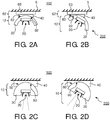
- Fig. 2A and 2B show schematic cross-sectional views of a further embodiment of an illumination system 102 in which the interface means 32 is oriented with respect to the heat sink 40 in two different orientations.
- the base 62 is constituted of the heat sink 40 and a substrate 63.
- the outer wall 92 of the heat sink 40 has the same shape as the outer wall 82 of the interface means 32.
- the directable magnetic mount 12 may be rotated to redirect the light emitter 20 to alter the emission direction of the light emitter 20.
- the magnetic connector 50, the electrical connectors 70 and the electrical supply contacts 75 are omitted for clarity reasons.
- the base 62 may be a rail 62 attached to a surface 5 or may be a fixture having a different shape, for example, square or round, as long as the heat sink 40 has sufficient heat capacity to cool the light emitter 20 sufficiently such that the light emitter 20 can be safely operated.
- the embodiment shown in Figs. 2A and 2B may be a partially cylindrical light source 202 or a partially spherical light source 202.
- the light emitter 20 can substantially only be redirected in one dimension by rotating the cylindrical light source 202 around a central axis (not shown) of the cylindrical shape of the outer wall 82 of the interface means 32.
- the embodiment of Figs. 2A and 2B represents a partial spherical light source 202
- the light emitter 20 can be redirected in two dimensions by rotating the spherical light source 202 around the center point (not shown) of the spherical shape of the outer wall 82 of the interface means 32.
- Figs. 2C and 2D show schematic cross-sectional views of the illumination system 100 as shown in Fig. 1 .
- the interface means 30 has a substantially larger volume compared to the embodiment shown in Figs. 2A and 2B .
- the interface means 30 may also be partially used as heat sink. Again, different orientations are shown and in each orientation the matching shape of the outer wall 90 of the heat sink 40 and the outer wall 80 of the interface means 30 ensure that good thermal conductivity from the light emitter 20 to the heat sink 40 is maintained.
- the cross sections shown in Figs. 2C and 2D may represent a substantially cylindrical light source 200 as shown in Fig. 1 .
- the cross sections shown in Figs. 2C and 2D may also represent a substantially spherical light source 200 which may allow a plurality of orientations of the interface means 30 with respect to the heat sink 40 in two dimensions.
- Figs. 3A to 3D show a plurality of schematic cross-sectional views of illumination systems 202, 204, 206, 208 according to the invention.
- the illumination system 102 shown in Fig. 3A is a copy of the illumination system shown in Figs. 2A and 2B and has been added for reference purposes.
- the light emitter 20 is arranged at one of the corners of the square shaped interface means 34.
- the light emitter 20 may be arranged at one of the sides of the square shaped interface means, between two subsequent corners.
- the interface means 34 shown in Fig. 3B may have a shape of a quadratic prism 34 or may have a cubic shape 34.
- the quadratic prism 34 allows a changing of orientation around an axis parallel to the central axis of the quadratic prism 34.
- the cubic shape 34 allows also a changing of orientation around a rotational axis R (indicated with a dash-dotted line) perpendicular to the surface 5.
- the illumination system 108 shown in Fig. 3D comprises a heat sink 40 having an outer wall 98 having a substantially polygonal shape.
- the light source 208 shown in Fig. 3D comprises a directable magnetic mount 18 comprising an interface means 38 again having a square shape 38 and having at least part of the outer wall 88 of the interface means 38 which matches the outer wall 98 of the heat sink 40.
- Three out of four sides of the square shaped interface means 38 have an outer wall 88 which matches the outer wall 98 of the heat sink 40 and as such, the orientation of the interface means 38 with respect to the heat sink 40 can be altered, thus altering the emission direction of the light emitter 20.
- the interface means 38 would also allow a changing of orientation around the rotational axis R (indicated with the dash-dotted line) perpendicular to the surface 5.
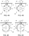
- Figs. 4A and 4B show the cross-sectional views of the illumination system 107 of Fig. 3C which now comprises two light emitters 20, 22.
- the orientation of the light source 207 may be altered with respect to the heat sink 40 via rotation of the light source 207 around an axis arranged substantially parallel to the heat sink 40 being parallel to the surface 5 or around the rotational axis R (indicated with a dash-dotted line).
- an indentation is provided in which, for example, one of the two light emitters 20, 22 may fit such that the light emitter is not visible and/or usable.
- the further light emitter 22 may, for example, emit light of a different color, intensity or having a different beam shape compared to the light emitter 20.
- the further light emitter 22 is identical to the light emitter 20 and a rotation of the light source 207 may enable both the light emitter 20 and the further light emitter 22 to contribute to the light emitted from the illumination system 107.
- the two schematic cross-sectional views of Figs. 4A and 4B illustrate only two of the many different orientation directions of the light source 207 relative to the heat sink 40.
- Figs. 4C and 4D show cross-sectional views of a slightly modified illumination system 109 of Fig. 3D in which the distance between the electrical connectors 70 is somewhat changed and which now also comprises two light emitters 20, 24, one of the two light emitters 24 having a beam-shaping lens 25.
- the orientation of the light source 209 may be altered with respect to the heat sink 40 via rotation of the light source 209 around an axis arranged substantially parallel to the heat sink 40 being parallel to the surface 5 or around the rotational axis R (indicated with a dash-dotted line).
- the beam-shaping lens 25 may, for example, cause the emission profile of the light emitted by the further light emitter 24 to be different compared to the emission profile of the light emitter 20.
- the change of orientation of the light source 209 may allow a user to alter the emission profile by changing the intensity variation emitted by the further light emitter 24.
- the beam-shaping lens 25 may alternatively comprise a filter 25 which is used to alter the color of the light emitted by the light emitter 24.
- an orientation of the light source 209 with respect to the heat sink 40 may be chosen such that both light emitters 20, 24 contribute to the emission of light from the illumination system 109. In such a case, different intensities, beam shapes and/or colors of light may be emitted in different directions from the illumination system 109.
- the electrical connectors 70 are indicated as movable pins 71 which are arranged in slots 72 and which are generally urged outwards out of the slots 72, for example, via springs (not shown). These springs ensure that the movable pins 71 are securely pressed against the electrical supply contacts 75 to ensure flawless power supply.
- the springs for urging out the movable pins 71 should not be stronger than the force with which the interface means 30 is urged against the heat sink 40 via the magnetic connector 50, because then the springs would prevent thorough thermal contact between the interface means 30 and the heat sink 40, thus endangering the light emitter 20 to become overheated.
- the heat sink 40 comprises ducts 110 for allowing cooling fluids (not shown) to pass through the heat sink 40.
- These ducts 110 may comprise a cooling liquid or may, for example, be open to allow air to pass through and as such increase the surface of the heat sink 40 to the environment, allowing the heat sink 40 to be cooled by convection of ambient air through the ducts 110.
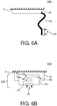
- Figs. 6A and 6B show alternative embodiments of illumination systems 400, 450 which use relatively large heat sinks 40 for cooling the light emitter 20, and comprising an interface means 130, 132 to conduct thermal energy away from the light emitter 20 to the heat sink 40.
- a large heat sink 40 is arranged, for example, at or near a surface 5 which may be a wall 5, ceiling 5, or any other surface 5.
- the light emitter 20 is connected to the interface means 130 which, for example, is a deformable duct 130 made of material able to conduct thermal energy well, for example, a metal.
- the heat conduction of the deformable duct 130 is increased if it has a large cross section. Since it has to be bendable, the best embodiment is probably a wide and thin metal plate 130.
- the light emitter 20 may conduct its thermal energy away from the light emitter 20 via the interface means 130 to the heat sink 40.
- the interface means 130 is constituted of a deformable duct
- the orientation of the light emitter with respect to the heat sink 40 can be done while maintaining a good conductivity of the thermal energy towards the heat sink 40.
- Power may be supplied via power conducting tracks (not shown) on, through or at the deformable duct 130.
- an elegant illumination system 400 may be obtained in which the direction of light emission of the light emitter 20 may be altered while the light emitter 20 may remain relatively small.
- the cooling requirements for high power LEDs are relatively strong and typically require cooling fins to be present at the light emitter 20 limiting design options of the light emitter 20 and the option to make the light emitter 20 small.
- an illumination system 450 is shown having a relatively large heat sink 40 which is arranged, for example, at or near a surface 5 which may be a wall 5, ceiling 5, or any other surface 5.
- the light emitter 20 is connected to the interface means 132 which, for example, has a cubic shape.
- the heat sink 40 may be a track along which the interface means 132 may be repositioned at will and which may be connected to the heat sink 40 via a magnetic connector 50, clamping means (not shown) or other fastening means as long as it results in a good thermal contact for conducting thermal energy via the interface means 132 away from the light emitter 20.
- the light source 120 being the light emitter 20 together with the interface means 132, may be relatively small.
- a characteristic of the current embodiment is that the projection of the interface means 132 is equal or smaller compared to the projection of the heat sink 40 acting as a rail 40.
- the track is relatively small compared to the light source and additional cooling fins are required to cool the light emitter.
- any reference signs placed between parentheses shall not be construed as limiting the claim.
- Use of the verb "comprise” and its conjugations does not exclude the presence of elements or steps other than those stated in a claim.
- the article “a” or “an” preceding an element does not exclude the presence of a plurality of such elements.
- the invention may be implemented by means of hardware comprising several distinct elements. In the device claim enumerating several means, several of these means may be embodied by one and the same item of hardware. The mere fact that certain measures are recited in mutually different dependent claims does not indicate that a combination of these measures cannot be used to advantage.
Landscapes
- Engineering & Computer Science (AREA)
- General Engineering & Computer Science (AREA)
- Microelectronics & Electronic Packaging (AREA)
- Architecture (AREA)
- Arrangement Of Elements, Cooling, Sealing, Or The Like Of Lighting Devices (AREA)
- Radiation-Therapy Devices (AREA)
Claims (15)
- Ausrichtbare magnetische Halterung (10, 12, 14, 16, 18), die mit einem Kühlung erfordernden Lichtemitter (20, 22, 24) elektrisch verbunden ist, wobei die ausrichtbare magnetische Halterung (10, 12, 14, 16, 18) umfasst:Schnittstellenmittel (30, 32, 34, 36, 38, 130, 132), die thermische Energie von dem Lichtemitter (20, 22, 24) weg zu einem Kühlkörper (40) leiten, sowieeinen magnetischen Steckverbinder (50), der die ausrichtbare magnetische Halterung (10, 12, 14, 16, 18) mit einer den Kühlkörper (40) umfassenden Basis (40, 62) magnetisch verbindet, wobei der magnetische Steckverbinder (50) so ausgeführt ist, dass er die Schnittstellenmittel (30, 32, 34, 36, 38) und den Kühlkörper (40) miteinander thermisch verbindet,wobei die Schnittstellenmittel (30, 32, 34, 36, 38) mit dem Kühlkörper (40) in mehreren Ausrichtungen der Schnittstellenmittel (30, 32, 34, 36, 38) gegenüber dem Kühlkörper (40) thermisch verbunden sind,dadurch gekennzeichnet, dass der magnetische Steckverbinder (50) außerhalb eines thermisch leitfähigen Pfads der Schnittstellenmittel (30, 32, 34, 36, 38) angeordnet ist.
- Ausrichtbare magnetische Halterung (10, 12, 14, 16, 18) nach Anspruch 1, wobei zumindest ein Teil einer äußeren Wand (80, 82, 84, 86, 88) der Schnittstellenmittel (30, 32, 34, 36, 38) eine erste Form umfasst, die so ausgeführt ist, dass sie mit einem Teil einer äußeren Wand (90, 92, 94, 96, 98) eines Kühlkörpers (40) mit einer mit der ersten Form zusammenpassenden zweiten Form thermisch verbunden ist.
- Ausrichtbare magnetische Halterung (10, 12, 14, 16, 18) nach Anspruch 1 oder 2, wobei die mehreren Ausrichtungen der Schnittstellenmittel (30, 32, 34, 36, 38) verschiedene Emissionscharakteristiken von Licht generieren, das von der ausrichtbaren magnetischen Halterung (10, 11, 14, 16, 18) emittiert wird, wobei die verschiedenen Emissionscharakteristiken umfassen:eine Emissionsrichtung des von der ausrichtbaren magnetischen Halterung (10, 11, 14, 16, 18) emittierten Lichts, und/odereine Form eines Bündels von, von der ausrichtbaren magnetischen Halterung (10, 11, 14, 16, 18) emittiertem Licht, und/odereine Farbe des von der ausrichtbaren magnetischen Halterung (10, 11, 14, 16, 18) emittierten Lichts, und/odereine Intensität und/oder eine Intensitätsverteilung des von der ausrichtbaren magnetischen Halterung (10, 11, 14, 16, 18) emittierten Lichts, und/odereine Anzahl von Lichtemittern (20, 22, 24), die Licht von der ausrichtbaren magnetischen Halterung (10, 11, 14, 16, 18) emittieren, bestehend aus einer Mehrzahl von Lichtemittern (20 22, 24).
- Ausrichtbare magnetische Halterung (10, 12, 14, 16, 18) nach Anspruch 1, 2 oder 3, wobei der magnetische Steckverbinder (50) von den Schnittstellenmitteln (30, 32, 34, 36, 38) thermisch isoliert ist.
- Ausrichtbare magnetische Halterung (10, 12, 14, 16, 18) nach Anspruch 1, 2, 3 oder 4, wobei die ausrichtbare magnetische Halterung (10, 12, 14, 16, 18) weiterhin mehrere elektrische Steckverbinder (70) umfasst, die so ausgeführt sind, dass sie bei Betrieb mit Stromversorgungskontakten (75) an der Basis (40, 62) verbunden sind, um dem Lichtemitter (20, 22, 24) Strom und/oder Steuerinformationen zuzuführen.
- Ausrichtbare magnetische Halterung (10, 12, 14, 16, 18) nach Anspruch 5, wobei die elektrischen Steckverbinder (70) an den Schnittstellenmitteln (30, 32, 34, 36, 38) angeordnet sind, und wobei die mehreren elektrischen Steckverbinder (70) aus mehr als zwei elektrischen Steckverbindern (70) bestehen, wobei die mehreren elektrischen Steckverbinder (70) über die Schnittstellenmittel (30, 32, 34, 36, 38) verteilt sind, um mindestens zwei elektrische Steckverbinder (70) der mehreren elektrischen Steckverbinder (70) mit den Stromversorgungskontakten (75) an den verschiedenen Ausrichtungen der Schnittstellenmittel (30, 32, 34, 36, 38) zu verbinden.
- Ausrichtbare magnetische Halterung (10, 12, 14, 16, 18) nach einem der Ansprüche 5 oder 6, wobei die ausrichtbare magnetische Halterung (10, 12, 14, 16, 18) weiterhin eine elektronische Schaltung (300) umfasst, um die Polarität von elektrischen Steckverbindern (70) der mehreren angeschlossenen elektrischen Steckverbinder (70) so anzupassen, dass sie der erforderlichen Polarität der Lichtquelle (200, 202, 204, 206, 208) entspricht.
- Ausrichtbare magnetische Halterung (10, 12, 14, 16, 18) nach einem der Ansprüche 2 bis 7, wobei die äußere Wand der Schnittstellenmittel (30, 32, 34, 36, 38) und die erste Form umfassen:eine gekrümmte Form beziehungsweise einen Teil der gekrümmten Form, odereine zylindrische Form beziehungsweise einen Teil der zylindrischen Form, odereine teilweise kugelförmige Form beziehungsweise einen Teil der teilweise kugelförmigen Form, oderein Polygon beziehungsweise eine Ecke des Polygons, oderein Polygon beziehungsweise mehrere Ecken des Polygons.
- Lichtquelle (200, 202, 204, 206, 207, 208, 209) mit einer ausrichtbaren magnetischen Halterung (10, 12, 14, 16, 18) nach den Ansprüchen 1 bis 8, wobei die ausrichtbare magnetische Halterung einen Lichtemitter (20, 22, 24) umfasst, der mit dem Kühlkörper (40) thermisch verbunden ist.
- Basis (40, 62), mit der eine ausrichtbare magnetische Halterung (10, 12, 14, 16, 18) nach einem der Ansprüche 1 bis 8 verbunden ist oder mit der eine Lichtquelle (200, 202, 204, 206, 208) nach Anspruch 9 verbunden ist, wobei die Basis (40, 62) umfasst:einen Kühlkörper (40), der thermische Energie von den mit dem Lichtemitter (20, 22, 24) verbundenen Schnittstellenmitteln (30, 32, 34, 36, 38) weg leitet, sowiein der Basis (40, 62) verteiltes magnetisch suszeptibles Material, das die ausrichtbare magnetische Halterung (10, 12, 14, 16, 18) oder die Lichtquelle (200, 202, 204, 206, 208) mit der Basis (40, 62) magnetisch verbindet und die Schnittstellenmittel (30, 32, 34, 36, 38) und den Kühlkörper (40) miteinander thermisch verbindet,wobei der Kühlkörper (40) mit den Schnittstellenmitteln (30, 32, 34, 36, 38) in mehreren Ausrichtungen der Schnittstellenmittel (30, 32, 34, 36, 38) gegenüber dem Kühlkörper (40) thermisch verbunden ist.
- Basis (40, 62) nach Anspruch 10, wobei die Basis (40, 62) Stromversorgungskontakte (75) umfasst, um dem Lichtemitter (20, 22, 24) über mindestens zwei der mehreren elektrischen Steckverbinder (70) der Schnittstellenmittel (30, 32, 34, 36, 38) Strom zuzuführen.
- Basis (40, 62) nach Anspruch 11, wobei die Basis (40, 62) eine Verteilung von magnetisch suszeptiblem Material umfasst, um die ausrichtbare magnetische Halterung (10, 12, 14, 16, 18) über den magnetischen Steckverbinder (50) an mehreren Stellen in Bezug auf den Kühlkörper (40) zu verbinden und dabei mindestens zwei elektrische Steckverbinder (70) der mehreren elektrischen Steckverbinder (70) mit den Stromversorgungskontakten (75) in den verschiedenen Emissionsrichtungen des Lichtemitters (20, 22, 24) zu verbinden.
- Basis (40, 62) nach Anspruch 10, 11 oder 12, wobei die Basis (40, 62) Leitungen (110) für Kühlflüssigkeit umfasst.
- Basis (40, 62) nach Anspruch 10, 11, 12 oder 13, wobei ein Teil einer äußeren Wand (90, 92, 94, 96, 98) des Kühlkörpers (40) eine zweite Form umfasst, die so ausgeführt ist, dass sie mit zumindest einem Teil einer äußeren Wand (80, 82, 84, 86, 88) der Schnittstellenmittel (30, 32, 34, 36, 38) mit einer mit der zweiten Form zusammenpassenden ersten Form thermisch verbunden ist, und wobei die zweite Form umfasst:eine gekrümmte Form odereine zylindrische Form odereine teilweise kugelförmige Form odereine dreieckige Form oderein Polygon.
- Beleuchtungssystem (100, 102, 104, 106, 107, 108, 109) mit der Lichtquelle (200, 202, 204, 206, 207, 208, 209) nach Anspruch 9 und mit der Basis (40, 62) nach einem der Ansprüche 10 bis 14.
Priority Applications (1)
| Application Number | Priority Date | Filing Date | Title |
|---|---|---|---|
| EP10705198.9A EP2401547B1 (de) | 2009-02-24 | 2010-02-17 | Ausrichtbare magnetische halterung für leuchte, lichtquelle, sockel und beleuchtungssystem |
Applications Claiming Priority (3)
| Application Number | Priority Date | Filing Date | Title |
|---|---|---|---|
| EP09153509 | 2009-02-24 | ||
| PCT/IB2010/050707 WO2010097733A1 (en) | 2009-02-24 | 2010-02-17 | Directable magnetic mount for light emitter, a light source, a base and an illumination system |
| EP10705198.9A EP2401547B1 (de) | 2009-02-24 | 2010-02-17 | Ausrichtbare magnetische halterung für leuchte, lichtquelle, sockel und beleuchtungssystem |
Publications (2)
| Publication Number | Publication Date |
|---|---|
| EP2401547A1 EP2401547A1 (de) | 2012-01-04 |
| EP2401547B1 true EP2401547B1 (de) | 2019-08-21 |
Family
ID=42211823
Family Applications (1)
| Application Number | Title | Priority Date | Filing Date |
|---|---|---|---|
| EP10705198.9A Active EP2401547B1 (de) | 2009-02-24 | 2010-02-17 | Ausrichtbare magnetische halterung für leuchte, lichtquelle, sockel und beleuchtungssystem |
Country Status (6)
| Country | Link |
|---|---|
| US (1) | US8851717B2 (de) |
| EP (1) | EP2401547B1 (de) |
| JP (1) | JP5530462B2 (de) |
| CN (1) | CN102333989B (de) |
| ES (1) | ES2749392T3 (de) |
| WO (1) | WO2010097733A1 (de) |
Families Citing this family (77)
| Publication number | Priority date | Publication date | Assignee | Title |
|---|---|---|---|---|
| DE4319806A1 (de) | 1993-06-15 | 1995-01-05 | Koenig & Bauer Ag | Papierstrangeinlauf in einem Längsfalztrichter |
| EP2269123A4 (de) * | 2008-03-20 | 2016-09-07 | Cooper Technologies Co | Energieverwaltungssystem |
| US8915609B1 (en) | 2008-03-20 | 2014-12-23 | Cooper Technologies Company | Systems, methods, and devices for providing a track light and portable light |
| US10371361B2 (en) * | 2010-09-30 | 2019-08-06 | Tseng-Lu Chien | Device has LED track means with removable LED-units which clip-on anywhere along the length or add-on from ends |
| US11476626B2 (en) * | 2008-11-12 | 2022-10-18 | Aaron Chien | DC powered remote control LED light-bar assembly |
| US8651711B2 (en) | 2009-02-02 | 2014-02-18 | Apex Technologies, Inc. | Modular lighting system and method employing loosely constrained magnetic structures |
| US9847636B2 (en) * | 2012-10-03 | 2017-12-19 | Ideal Industries, Inc. | Low voltage buss system |
| US20130176750A1 (en) * | 2011-09-02 | 2013-07-11 | The Procter & Gamble Company | Light emitting apparatus |
| DE102010040892B4 (de) | 2010-09-16 | 2012-07-12 | Osram Ag | Leuchtvorrichtung mit Kühlkörper und Verfahren zum Ausrichten eines von einer Leuchtvorrichtung ausgestrahlten Lichtbündels |
| US9822951B2 (en) | 2010-12-06 | 2017-11-21 | Cree, Inc. | LED retrofit lens for fluorescent tube |
| US10309627B2 (en) * | 2012-11-08 | 2019-06-04 | Cree, Inc. | Light fixture retrofit kit with integrated light bar |
| CN103597284B (zh) * | 2011-06-17 | 2017-06-20 | 飞利浦灯具控股公司 | 枢转的热转移接合件 |
| US9188290B2 (en) | 2012-04-10 | 2015-11-17 | Cree, Inc. | Indirect linear fixture |
| ITBS20120060A1 (it) * | 2012-04-13 | 2013-10-14 | Flos Spa | Dispositivo di illuminazione da incasso con faretti sganciabili |
| US8770993B2 (en) * | 2012-06-01 | 2014-07-08 | Tyco Electronics Corporation | Connector assembly with polarity correction/protection |
| US20140016333A1 (en) * | 2012-07-12 | 2014-01-16 | Scott S. Yu | Modular fixture system |
| US8917171B2 (en) * | 2012-09-07 | 2014-12-23 | J. Thomas Anderson | Vehicle warning light system and method |
| US10186801B2 (en) * | 2012-10-03 | 2019-01-22 | Ideal Industries, Inc. | Low voltage buss system |
| DE202012104136U1 (de) * | 2012-10-29 | 2014-02-04 | Zumtobel Lighting Gmbh | Leuchte mit verdrehbarer Optikeinheit |
| US9482396B2 (en) | 2012-11-08 | 2016-11-01 | Cree, Inc. | Integrated linear light engine |
| US9441818B2 (en) | 2012-11-08 | 2016-09-13 | Cree, Inc. | Uplight with suspended fixture |
| US9494304B2 (en) | 2012-11-08 | 2016-11-15 | Cree, Inc. | Recessed light fixture retrofit kit |
| US10788176B2 (en) | 2013-02-08 | 2020-09-29 | Ideal Industries Lighting Llc | Modular LED lighting system |
| DE202012104421U1 (de) * | 2012-11-16 | 2014-02-17 | Zumtobel Lighting Gmbh | Magnet zur magnetischen Befestigung von Leuchten, Beleuchtungsvorrichtung und Metallregal |
| CN105026826B (zh) * | 2013-03-07 | 2018-02-23 | 飞利浦灯具控股公司 | 照明系统、用于其的轨道和照明模块 |
| BR112015021284A2 (pt) | 2013-03-07 | 2017-07-18 | Koninklijke Philips Nv | sistema de iluminação, calha adequada para uso no sistema de iluminação e módulo de iluminação adequado para uso no sistema de iluminação |
| ES2634016T3 (es) * | 2013-03-07 | 2017-09-26 | Philips Lighting Holding B.V. | Sistema de iluminación, pista y módulo de iluminación del mismo |
| US10584860B2 (en) | 2013-03-14 | 2020-03-10 | Ideal Industries, Llc | Linear light fixture with interchangeable light engine unit |
| US9874333B2 (en) | 2013-03-14 | 2018-01-23 | Cree, Inc. | Surface ambient wrap light fixture |
| USD738026S1 (en) | 2013-03-14 | 2015-09-01 | Cree, Inc. | Linear wrap light fixture |
| TWI599500B (zh) * | 2013-03-14 | 2017-09-21 | 緯創資通股份有限公司 | 用來固定可攜式電子裝置之固定機構及其電子設備 |
| US10680383B2 (en) | 2013-03-14 | 2020-06-09 | Apex Technologies, Inc. | Linear electrode systems for module attachment with non-uniform axial spacing |
| US10132452B2 (en) | 2013-03-14 | 2018-11-20 | Apex Technologies, Inc. | Suspended track and planar electrode systems and methods |
| USD733952S1 (en) | 2013-03-15 | 2015-07-07 | Cree, Inc. | Indirect linear fixture |
| US9559456B2 (en) * | 2013-03-15 | 2017-01-31 | Google Technology Holdings LLC | Magnetic electrical connection system for an electronic device |
| US9461024B2 (en) | 2013-08-01 | 2016-10-04 | Cree, Inc. | Light emitter devices and methods for light emitting diode (LED) chips |
| CN203404760U (zh) * | 2013-08-27 | 2014-01-22 | 肖志蓝 | 一种可偏转角度的嵌入式led灯具的圆弧散热装置 |
| JP2015083283A (ja) * | 2013-10-25 | 2015-04-30 | 京セラ株式会社 | 光照射モジュールおよび印刷装置 |
| US10900653B2 (en) | 2013-11-01 | 2021-01-26 | Cree Hong Kong Limited | LED mini-linear light engine |
| US10100988B2 (en) | 2013-12-16 | 2018-10-16 | Cree, Inc. | Linear shelf light fixture with reflectors |
| USD750308S1 (en) | 2013-12-16 | 2016-02-23 | Cree, Inc. | Linear shelf light fixture |
| US10612747B2 (en) | 2013-12-16 | 2020-04-07 | Ideal Industries Lighting Llc | Linear shelf light fixture with gap filler elements |
| US10247401B2 (en) | 2013-12-20 | 2019-04-02 | Feelux Co., Ltd. | Lighting device |
| CN104763981B (zh) * | 2014-01-06 | 2018-05-22 | 连立华 | Led灯具的热沉外壳及使用该热沉外壳的led灯具 |
| PL3129716T3 (pl) * | 2014-04-07 | 2019-09-30 | Elica S.P.A. | Okap domowy |
| USD757324S1 (en) | 2014-04-14 | 2016-05-24 | Cree, Inc. | Linear shelf light fixture with reflectors |
| DE202014104416U1 (de) * | 2014-09-17 | 2015-12-18 | Zumtobel Lighting Gmbh | Leuchtenkupplung für Beleuchtungssystem |
| WO2016120498A1 (es) * | 2015-01-26 | 2016-08-04 | C. & G. Carandini, S.A. | Luminaria de leds para tuneles y similares |
| EP3056799B1 (de) * | 2015-02-13 | 2017-03-08 | Urama GmbH | Leuchte |
| WO2016132362A1 (en) * | 2015-02-17 | 2016-08-25 | Chocolate Lighting Company Ltd | Power contact assembly for a track lighting system |
| JP6444814B2 (ja) * | 2015-06-17 | 2018-12-26 | 株式会社 ワン・バイ・ワン | 照明装置 |
| ITUB20155603A1 (it) * | 2015-11-16 | 2017-05-16 | A2Cg S R L | Sistema di illuminazione modulare orientabile |
| DE102015226625B4 (de) * | 2015-12-23 | 2017-09-14 | H4X E.U. | Beleuchtungsanordnung, sowie Verfahren zum Aufbau einer Beleuchtungsanordnung |
| CA2951310A1 (en) * | 2015-12-31 | 2017-06-30 | Ideal Industries, Inc. | Low voltage buss system |
| US10367296B2 (en) * | 2016-03-04 | 2019-07-30 | Ecco Design, Inc. | Modular electrical power supply and control system |
| US11092293B2 (en) * | 2016-04-11 | 2021-08-17 | Artemide S.P.A. | Modular lighting system |
| US9995445B2 (en) * | 2016-05-17 | 2018-06-12 | Tang-Hao Chien | Lighting system having improved unidirectional intensity |
| EP3263975B1 (de) | 2016-07-01 | 2018-06-27 | Mittelland GmbH | Leuchte |
| US11408596B1 (en) | 2016-08-31 | 2022-08-09 | Artifox, LLC | Light tube |
| KR101873785B1 (ko) * | 2016-11-29 | 2018-07-03 | 양문선 | 조명 장치 |
| KR101901259B1 (ko) | 2016-11-30 | 2018-09-27 | 김용민 | 소비전력 측정장치가 구비된 조명레일 시스템 |
| PL422209A1 (pl) * | 2017-07-13 | 2019-01-14 | SZYMAŃSKI Andrzej LARS | Element świetlny, zwłaszcza do sufitu podwieszanego |
| KR101979514B1 (ko) * | 2017-11-28 | 2019-05-16 | 김형두 | 모듈형 레일조명기구 |
| US11242982B2 (en) * | 2018-02-22 | 2022-02-08 | Kh Feelux Co., Ltd. | Lighting unit and rail type lighting device comprising same |
| WO2020018870A1 (en) | 2018-07-20 | 2020-01-23 | Emoov, Llc | Mounting assembly for installation of powered module |
| US10684001B1 (en) * | 2018-08-07 | 2020-06-16 | Michael E. Beckman | Detachable flood light assembly |
| FR3091746B1 (fr) * | 2019-01-14 | 2023-03-03 | Soc Financiere Veron Sofive | Luminaire en deux parties avec portions d’éclairage et intermédiaire |
| US10783810B1 (en) * | 2019-03-21 | 2020-09-22 | Tectonics Industries, LLC | Illumination display platforms and related methods |
| CN110160752B (zh) * | 2019-06-06 | 2022-04-19 | 江苏毅昌科技有限公司 | 一种光源测试装置 |
| US11937735B2 (en) * | 2019-08-08 | 2024-03-26 | The Vollrath Company, L.L.C. | Reconfigurable food warming assembly |
| WO2021072412A1 (en) * | 2019-10-10 | 2021-04-15 | TTP Holdings, LLC | Modular system |
| US11796161B2 (en) * | 2020-05-11 | 2023-10-24 | Wangs Alliance Corporation | Fixtures, power and control systems for same |
| EP4256229A4 (de) * | 2020-12-04 | 2025-01-08 | Milwaukee Electric Tool Corporation | Scheinwerfer mit abnehmbarer leuchtanordnung |
| DE102022127156A1 (de) | 2022-10-18 | 2024-04-18 | Apl Ag | Stecksystem |
| FR3142278B1 (fr) * | 2022-11-17 | 2025-02-21 | Aratice | Système d’affichage suspendu |
| US12111040B2 (en) | 2023-01-27 | 2024-10-08 | Wangs Alliance Corporation | Small aperture light emitting diode LED lighting |
| US12228274B2 (en) | 2023-07-18 | 2025-02-18 | Wangs Alliance Corporation | Low glare fixture |
Citations (1)
| Publication number | Priority date | Publication date | Assignee | Title |
|---|---|---|---|---|
| US20130044501A1 (en) * | 2009-02-02 | 2013-02-21 | Charles A. Rudisill | Modular lighting system and method employing loosely constrained magnetic structures |
Family Cites Families (17)
| Publication number | Priority date | Publication date | Assignee | Title |
|---|---|---|---|---|
| FR2033490A5 (de) | 1969-02-26 | 1970-12-04 | Girard Christian | |
| DE2643780A1 (de) * | 1976-09-29 | 1978-03-30 | Helmut Zanker | Kippbare standleuchte |
| DE3447332A1 (de) * | 1984-12-24 | 1986-07-03 | Volker H. P. Dipl.-Ing. 8000 München Apel | Verbindung zwischen zwei mechanisch und elektrisch loesbar miteinander verbundenen teilen insbesondere eines beleuchtungssystems |
| US5154509A (en) | 1992-01-15 | 1992-10-13 | 291, Inc. | Low voltage magnetic track light system |
| JPH07254461A (ja) * | 1994-03-16 | 1995-10-03 | Nec Eng Ltd | 回転式アングルタイプコネクタ |
| DE19628573A1 (de) | 1996-07-16 | 1998-01-22 | Andreas Heymann | Magnetkontaktsystem zum kabellosen Anschluß von Halogen- bzw. Niederspannungsleuchten |
| JP3033766B1 (ja) * | 1999-03-11 | 2000-04-17 | 甲府日本電気株式会社 | コネクタ |
| US7137727B2 (en) | 2000-07-31 | 2006-11-21 | Litesnow Llc | Electrical track lighting system |
| JP2002175722A (ja) * | 2000-12-08 | 2002-06-21 | Matsushita Electric Works Ltd | 照明装置の放熱構造 |
| JP4105449B2 (ja) * | 2002-02-22 | 2008-06-25 | 俊昭 遠藤 | 作業用電灯 |
| US6877880B2 (en) | 2002-12-13 | 2005-04-12 | Toshiaki Endo | Electric light for work |
| FI3770980T3 (fi) | 2005-05-20 | 2024-09-27 | Signify Holding Bv | Valoa emittoiva moduuli |
| KR101333022B1 (ko) * | 2005-09-22 | 2013-11-26 | 코닌클리케 필립스 엔.브이. | Led 조명 모듈 및 조명 조립품 |
| US20070076426A1 (en) * | 2005-10-03 | 2007-04-05 | Kling Michael R | Lamp with two light sources |
| JP2008218386A (ja) * | 2007-02-09 | 2008-09-18 | Toyoda Gosei Co Ltd | 発光装置 |
| US7854614B2 (en) * | 2007-12-14 | 2010-12-21 | Robb John R | Multi-contact universally jointed power and/or signal connector devices |
| US8187006B2 (en) * | 2009-02-02 | 2012-05-29 | Apex Technologies, Inc | Flexible magnetic interconnects |
-
2010
- 2010-02-17 EP EP10705198.9A patent/EP2401547B1/de active Active
- 2010-02-17 US US13/203,011 patent/US8851717B2/en active Active
- 2010-02-17 ES ES10705198T patent/ES2749392T3/es active Active
- 2010-02-17 JP JP2011550688A patent/JP5530462B2/ja active Active
- 2010-02-17 WO PCT/IB2010/050707 patent/WO2010097733A1/en not_active Ceased
- 2010-02-17 CN CN201080009724.2A patent/CN102333989B/zh active Active
Patent Citations (1)
| Publication number | Priority date | Publication date | Assignee | Title |
|---|---|---|---|---|
| US20130044501A1 (en) * | 2009-02-02 | 2013-02-21 | Charles A. Rudisill | Modular lighting system and method employing loosely constrained magnetic structures |
Also Published As
| Publication number | Publication date |
|---|---|
| WO2010097733A1 (en) | 2010-09-02 |
| JP5530462B2 (ja) | 2014-06-25 |
| JP2012518882A (ja) | 2012-08-16 |
| CN102333989B (zh) | 2014-04-02 |
| ES2749392T3 (es) | 2020-03-20 |
| US20120075857A1 (en) | 2012-03-29 |
| EP2401547A1 (de) | 2012-01-04 |
| CN102333989A (zh) | 2012-01-25 |
| US8851717B2 (en) | 2014-10-07 |
Similar Documents
| Publication | Publication Date | Title |
|---|---|---|
| EP2401547B1 (de) | Ausrichtbare magnetische halterung für leuchte, lichtquelle, sockel und beleuchtungssystem | |
| US8449138B2 (en) | Lighting device | |
| US9863625B2 (en) | Modular luminaire system | |
| CN103052838B (zh) | Led灯泡 | |
| US8272762B2 (en) | LED luminaire | |
| US20110170288A1 (en) | Led retrofit unit having adjustable heads for street lighting | |
| US11898706B2 (en) | Illuminating device | |
| US9157618B2 (en) | Trough luminaire with magnetic lighting devices and associated systems and methods | |
| US20110116266A1 (en) | Led bulb with modules having side-emitting light emitting diodes and rotatable base | |
| KR102125887B1 (ko) | 발광 장치 및 램프 | |
| JP5835815B2 (ja) | モジュール式発光ダイオード回路組立体のための装置、方法、及びシステム | |
| US9249968B2 (en) | Heat-dissipating light-emitting device and method for its assembly | |
| CN103807622A (zh) | 照明装置 | |
| CN215174879U (zh) | 一种展示灯、磁性轨道及柔性展示灯系统 | |
| KR101291110B1 (ko) | Led 칩 패키지 | |
| KR101860039B1 (ko) | 조명 장치 |
Legal Events
| Date | Code | Title | Description |
|---|---|---|---|
| PUAI | Public reference made under article 153(3) epc to a published international application that has entered the european phase |
Free format text: ORIGINAL CODE: 0009012 |
|
| 17P | Request for examination filed |
Effective date: 20110926 |
|
| AK | Designated contracting states |
Kind code of ref document: A1 Designated state(s): AT BE BG CH CY CZ DE DK EE ES FI FR GB GR HR HU IE IS IT LI LT LU LV MC MK MT NL NO PL PT RO SE SI SK SM TR |
|
| DAX | Request for extension of the european patent (deleted) | ||
| RAP1 | Party data changed (applicant data changed or rights of an application transferred) |
Owner name: KONINKLIJKE PHILIPS N.V. |
|
| RAP1 | Party data changed (applicant data changed or rights of an application transferred) |
Owner name: PHILIPS LIGHTING HOLDING B.V. |
|
| STAA | Information on the status of an ep patent application or granted ep patent |
Free format text: STATUS: EXAMINATION IS IN PROGRESS |
|
| 17Q | First examination report despatched |
Effective date: 20170113 |
|
| RIN1 | Information on inventor provided before grant (corrected) |
Inventor name: VERBRUGH, STEFAN, M. |
|
| GRAP | Despatch of communication of intention to grant a patent |
Free format text: ORIGINAL CODE: EPIDOSNIGR1 |
|
| STAA | Information on the status of an ep patent application or granted ep patent |
Free format text: STATUS: GRANT OF PATENT IS INTENDED |
|
| RAP1 | Party data changed (applicant data changed or rights of an application transferred) |
Owner name: PHILIPS LIGHTING HOLDING B.V. |
|
| INTG | Intention to grant announced |
Effective date: 20181123 |
|
| GRAJ | Information related to disapproval of communication of intention to grant by the applicant or resumption of examination proceedings by the epo deleted |
Free format text: ORIGINAL CODE: EPIDOSDIGR1 |
|
| STAA | Information on the status of an ep patent application or granted ep patent |
Free format text: STATUS: EXAMINATION IS IN PROGRESS |
|
| GRAP | Despatch of communication of intention to grant a patent |
Free format text: ORIGINAL CODE: EPIDOSNIGR1 |
|
| STAA | Information on the status of an ep patent application or granted ep patent |
Free format text: STATUS: GRANT OF PATENT IS INTENDED |
|
| RAP1 | Party data changed (applicant data changed or rights of an application transferred) |
Owner name: SIGNIFY HOLDING B.V. |
|
| INTC | Intention to grant announced (deleted) | ||
| INTG | Intention to grant announced |
Effective date: 20190313 |
|
| GRAS | Grant fee paid |
Free format text: ORIGINAL CODE: EPIDOSNIGR3 |
|
| GRAA | (expected) grant |
Free format text: ORIGINAL CODE: 0009210 |
|
| STAA | Information on the status of an ep patent application or granted ep patent |
Free format text: STATUS: THE PATENT HAS BEEN GRANTED |
|
| AK | Designated contracting states |
Kind code of ref document: B1 Designated state(s): AT BE BG CH CY CZ DE DK EE ES FI FR GB GR HR HU IE IS IT LI LT LU LV MC MK MT NL NO PL PT RO SE SI SK SM TR |
|
| REG | Reference to a national code |
Ref country code: GB Ref legal event code: FG4D |
|
| REG | Reference to a national code |
Ref country code: CH Ref legal event code: EP |
|
| REG | Reference to a national code |
Ref country code: DE Ref legal event code: R096 Ref document number: 602010060642 Country of ref document: DE |
|
| REG | Reference to a national code |
Ref country code: AT Ref legal event code: REF Ref document number: 1170179 Country of ref document: AT Kind code of ref document: T Effective date: 20190915 |
|
| REG | Reference to a national code |
Ref country code: IE Ref legal event code: FG4D |
|
| REG | Reference to a national code |
Ref country code: LT Ref legal event code: MG4D |
|
| REG | Reference to a national code |
Ref country code: NL Ref legal event code: MP Effective date: 20190821 |
|
| PG25 | Lapsed in a contracting state [announced via postgrant information from national office to epo] |
Ref country code: SE Free format text: LAPSE BECAUSE OF FAILURE TO SUBMIT A TRANSLATION OF THE DESCRIPTION OR TO PAY THE FEE WITHIN THE PRESCRIBED TIME-LIMIT Effective date: 20190821 Ref country code: NL Free format text: LAPSE BECAUSE OF FAILURE TO SUBMIT A TRANSLATION OF THE DESCRIPTION OR TO PAY THE FEE WITHIN THE PRESCRIBED TIME-LIMIT Effective date: 20190821 Ref country code: NO Free format text: LAPSE BECAUSE OF FAILURE TO SUBMIT A TRANSLATION OF THE DESCRIPTION OR TO PAY THE FEE WITHIN THE PRESCRIBED TIME-LIMIT Effective date: 20191121 Ref country code: BG Free format text: LAPSE BECAUSE OF FAILURE TO SUBMIT A TRANSLATION OF THE DESCRIPTION OR TO PAY THE FEE WITHIN THE PRESCRIBED TIME-LIMIT Effective date: 20191121 Ref country code: LT Free format text: LAPSE BECAUSE OF FAILURE TO SUBMIT A TRANSLATION OF THE DESCRIPTION OR TO PAY THE FEE WITHIN THE PRESCRIBED TIME-LIMIT Effective date: 20190821 Ref country code: FI Free format text: LAPSE BECAUSE OF FAILURE TO SUBMIT A TRANSLATION OF THE DESCRIPTION OR TO PAY THE FEE WITHIN THE PRESCRIBED TIME-LIMIT Effective date: 20190821 Ref country code: PT Free format text: LAPSE BECAUSE OF FAILURE TO SUBMIT A TRANSLATION OF THE DESCRIPTION OR TO PAY THE FEE WITHIN THE PRESCRIBED TIME-LIMIT Effective date: 20191223 Ref country code: HR Free format text: LAPSE BECAUSE OF FAILURE TO SUBMIT A TRANSLATION OF THE DESCRIPTION OR TO PAY THE FEE WITHIN THE PRESCRIBED TIME-LIMIT Effective date: 20190821 |
|
| PG25 | Lapsed in a contracting state [announced via postgrant information from national office to epo] |
Ref country code: LV Free format text: LAPSE BECAUSE OF FAILURE TO SUBMIT A TRANSLATION OF THE DESCRIPTION OR TO PAY THE FEE WITHIN THE PRESCRIBED TIME-LIMIT Effective date: 20190821 Ref country code: IS Free format text: LAPSE BECAUSE OF FAILURE TO SUBMIT A TRANSLATION OF THE DESCRIPTION OR TO PAY THE FEE WITHIN THE PRESCRIBED TIME-LIMIT Effective date: 20191221 Ref country code: GR Free format text: LAPSE BECAUSE OF FAILURE TO SUBMIT A TRANSLATION OF THE DESCRIPTION OR TO PAY THE FEE WITHIN THE PRESCRIBED TIME-LIMIT Effective date: 20191122 |
|
| REG | Reference to a national code |
Ref country code: AT Ref legal event code: MK05 Ref document number: 1170179 Country of ref document: AT Kind code of ref document: T Effective date: 20190821 |
|
| REG | Reference to a national code |
Ref country code: ES Ref legal event code: FG2A Ref document number: 2749392 Country of ref document: ES Kind code of ref document: T3 Effective date: 20200320 |
|
| PG25 | Lapsed in a contracting state [announced via postgrant information from national office to epo] |
Ref country code: TR Free format text: LAPSE BECAUSE OF FAILURE TO SUBMIT A TRANSLATION OF THE DESCRIPTION OR TO PAY THE FEE WITHIN THE PRESCRIBED TIME-LIMIT Effective date: 20190821 |
|
| PG25 | Lapsed in a contracting state [announced via postgrant information from national office to epo] |
Ref country code: AT Free format text: LAPSE BECAUSE OF FAILURE TO SUBMIT A TRANSLATION OF THE DESCRIPTION OR TO PAY THE FEE WITHIN THE PRESCRIBED TIME-LIMIT Effective date: 20190821 Ref country code: DK Free format text: LAPSE BECAUSE OF FAILURE TO SUBMIT A TRANSLATION OF THE DESCRIPTION OR TO PAY THE FEE WITHIN THE PRESCRIBED TIME-LIMIT Effective date: 20190821 Ref country code: EE Free format text: LAPSE BECAUSE OF FAILURE TO SUBMIT A TRANSLATION OF THE DESCRIPTION OR TO PAY THE FEE WITHIN THE PRESCRIBED TIME-LIMIT Effective date: 20190821 Ref country code: PL Free format text: LAPSE BECAUSE OF FAILURE TO SUBMIT A TRANSLATION OF THE DESCRIPTION OR TO PAY THE FEE WITHIN THE PRESCRIBED TIME-LIMIT Effective date: 20190821 Ref country code: RO Free format text: LAPSE BECAUSE OF FAILURE TO SUBMIT A TRANSLATION OF THE DESCRIPTION OR TO PAY THE FEE WITHIN THE PRESCRIBED TIME-LIMIT Effective date: 20190821 |
|
| PG25 | Lapsed in a contracting state [announced via postgrant information from national office to epo] |
Ref country code: IS Free format text: LAPSE BECAUSE OF FAILURE TO SUBMIT A TRANSLATION OF THE DESCRIPTION OR TO PAY THE FEE WITHIN THE PRESCRIBED TIME-LIMIT Effective date: 20200224 Ref country code: CZ Free format text: LAPSE BECAUSE OF FAILURE TO SUBMIT A TRANSLATION OF THE DESCRIPTION OR TO PAY THE FEE WITHIN THE PRESCRIBED TIME-LIMIT Effective date: 20190821 Ref country code: SK Free format text: LAPSE BECAUSE OF FAILURE TO SUBMIT A TRANSLATION OF THE DESCRIPTION OR TO PAY THE FEE WITHIN THE PRESCRIBED TIME-LIMIT Effective date: 20190821 Ref country code: SM Free format text: LAPSE BECAUSE OF FAILURE TO SUBMIT A TRANSLATION OF THE DESCRIPTION OR TO PAY THE FEE WITHIN THE PRESCRIBED TIME-LIMIT Effective date: 20190821 |
|
| REG | Reference to a national code |
Ref country code: DE Ref legal event code: R097 Ref document number: 602010060642 Country of ref document: DE |
|
| PLBE | No opposition filed within time limit |
Free format text: ORIGINAL CODE: 0009261 |
|
| STAA | Information on the status of an ep patent application or granted ep patent |
Free format text: STATUS: NO OPPOSITION FILED WITHIN TIME LIMIT |
|
| PG2D | Information on lapse in contracting state deleted |
Ref country code: IS |
|
| 26N | No opposition filed |
Effective date: 20200603 |
|
| PG25 | Lapsed in a contracting state [announced via postgrant information from national office to epo] |
Ref country code: SI Free format text: LAPSE BECAUSE OF FAILURE TO SUBMIT A TRANSLATION OF THE DESCRIPTION OR TO PAY THE FEE WITHIN THE PRESCRIBED TIME-LIMIT Effective date: 20190821 |
|
| REG | Reference to a national code |
Ref country code: CH Ref legal event code: PL |
|
| REG | Reference to a national code |
Ref country code: BE Ref legal event code: MM Effective date: 20200229 |
|
| PG25 | Lapsed in a contracting state [announced via postgrant information from national office to epo] |
Ref country code: MC Free format text: LAPSE BECAUSE OF FAILURE TO SUBMIT A TRANSLATION OF THE DESCRIPTION OR TO PAY THE FEE WITHIN THE PRESCRIBED TIME-LIMIT Effective date: 20190821 Ref country code: LU Free format text: LAPSE BECAUSE OF NON-PAYMENT OF DUE FEES Effective date: 20200217 |
|
| PG25 | Lapsed in a contracting state [announced via postgrant information from national office to epo] |
Ref country code: CH Free format text: LAPSE BECAUSE OF NON-PAYMENT OF DUE FEES Effective date: 20200229 Ref country code: LI Free format text: LAPSE BECAUSE OF NON-PAYMENT OF DUE FEES Effective date: 20200229 |
|
| PG25 | Lapsed in a contracting state [announced via postgrant information from national office to epo] |
Ref country code: IE Free format text: LAPSE BECAUSE OF NON-PAYMENT OF DUE FEES Effective date: 20200217 |
|
| PG25 | Lapsed in a contracting state [announced via postgrant information from national office to epo] |
Ref country code: BE Free format text: LAPSE BECAUSE OF NON-PAYMENT OF DUE FEES Effective date: 20200229 |
|
| PG25 | Lapsed in a contracting state [announced via postgrant information from national office to epo] |
Ref country code: MT Free format text: LAPSE BECAUSE OF FAILURE TO SUBMIT A TRANSLATION OF THE DESCRIPTION OR TO PAY THE FEE WITHIN THE PRESCRIBED TIME-LIMIT Effective date: 20190821 Ref country code: CY Free format text: LAPSE BECAUSE OF FAILURE TO SUBMIT A TRANSLATION OF THE DESCRIPTION OR TO PAY THE FEE WITHIN THE PRESCRIBED TIME-LIMIT Effective date: 20190821 |
|
| PG25 | Lapsed in a contracting state [announced via postgrant information from national office to epo] |
Ref country code: MK Free format text: LAPSE BECAUSE OF FAILURE TO SUBMIT A TRANSLATION OF THE DESCRIPTION OR TO PAY THE FEE WITHIN THE PRESCRIBED TIME-LIMIT Effective date: 20190821 |
|
| P01 | Opt-out of the competence of the unified patent court (upc) registered |
Effective date: 20230421 |
|
| PGFP | Annual fee paid to national office [announced via postgrant information from national office to epo] |
Ref country code: ES Payment date: 20250312 Year of fee payment: 16 |
|
| PGFP | Annual fee paid to national office [announced via postgrant information from national office to epo] |
Ref country code: FR Payment date: 20250224 Year of fee payment: 16 |
|
| PGFP | Annual fee paid to national office [announced via postgrant information from national office to epo] |
Ref country code: IT Payment date: 20250225 Year of fee payment: 16 Ref country code: GB Payment date: 20250218 Year of fee payment: 16 |
|
| PGFP | Annual fee paid to national office [announced via postgrant information from national office to epo] |
Ref country code: DE Payment date: 20250428 Year of fee payment: 16 |