EP2401083B1 - Rührwerkskugelmühle - Google Patents
Rührwerkskugelmühle Download PDFInfo
- Publication number
- EP2401083B1 EP2401083B1 EP10706203.6A EP10706203A EP2401083B1 EP 2401083 B1 EP2401083 B1 EP 2401083B1 EP 10706203 A EP10706203 A EP 10706203A EP 2401083 B1 EP2401083 B1 EP 2401083B1
- Authority
- EP
- European Patent Office
- Prior art keywords
- agitator
- ball mill
- outlet
- screen
- end wall
- Prior art date
- Legal status (The legal status is an assumption and is not a legal conclusion. Google has not performed a legal analysis and makes no representation as to the accuracy of the status listed.)
- Active
Links
Images

Classifications
-
- B—PERFORMING OPERATIONS; TRANSPORTING
- B02—CRUSHING, PULVERISING, OR DISINTEGRATING; PREPARATORY TREATMENT OF GRAIN FOR MILLING
- B02C—CRUSHING, PULVERISING, OR DISINTEGRATING IN GENERAL; MILLING GRAIN
- B02C17/00—Disintegrating by tumbling mills, i.e. mills having a container charged with the material to be disintegrated with or without special disintegrating members such as pebbles or balls
- B02C17/16—Mills in which a fixed container houses stirring means tumbling the charge
- B02C17/161—Arrangements for separating milling media and ground material
-
- B—PERFORMING OPERATIONS; TRANSPORTING
- B02—CRUSHING, PULVERISING, OR DISINTEGRATING; PREPARATORY TREATMENT OF GRAIN FOR MILLING
- B02C—CRUSHING, PULVERISING, OR DISINTEGRATING IN GENERAL; MILLING GRAIN
- B02C17/00—Disintegrating by tumbling mills, i.e. mills having a container charged with the material to be disintegrated with or without special disintegrating members such as pebbles or balls
- B02C17/16—Mills in which a fixed container houses stirring means tumbling the charge
- B02C17/163—Stirring means
Definitions
- the invention relates to a stirred ball mill with a grinding chamber which is delimited by a side wall and one inlet and one outlet end wall, arranged in the grinding chamber agitator with a rotatably mounted and driven agitator shaft and arranged on her accelerators, arranged near the inlet side end wall Inlet for grinding stock and grinding media, a Mahlgutauslass arranged in the outlet-side end wall, which is separated by a sieve of the grinding chamber.
- This device consists essentially in making the distance between the last disc of the agitator and the separator so small that the mixture of grinding stock and grinding media is accelerated more in this space than in the rest of the grinding chamber and thus the "pre-classification" separation takes place. So should be achieved that even less or no coarse grinding more go to the sieve.
- EP-627262 describes a stirred ball mill with accelerators in the form of paddle wheels.
- the separation device is not in a sieve, but in an annular gap, so that this document is not about the problem of adding the sieve.
- the invention is therefore based on the object to prevent the clogging of the screen in a different and more effective manner.
- upstream and downstream are used with respect to the direction of the millbase flow through the mill, i. H. from the grinding stock inlet down to the grinding stock outlet, also used for constructional features.
- This millbase stream is marked with the black arrows.
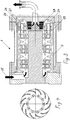
- the agitator ball mill 1 shown in axial section has a housing of a cylindrical side wall 2, an inlet-side planar end wall 3 and an outlet-side planar end wall 4.
- the side wall and the end walls define a grinding chamber 5.
- an agitator is arranged, consisting of a in the inlet-side end wall rotatably mounted stirrer shaft. 6 and there are three accelerators in the same distance from each other in the form of paddle wheels 7, 8, 9.
- the inlet-side paddle wheel 7 and the central paddle wheel 8 are identical and consist of a fixedly connected to the agitator shaft 6 middle disc 10 with attached near the agitator shaft axis-parallel holes 11 and both sides thereof arranged annular discs 12, wherein between these discs a number of the same Angular distances arranged wings 13 extends.
- the outer disks 12 have an opening 14 extending annularly around the agitator shaft 6.
- the paddle wheels can be constructed differently, so for example, each consist of two parallel discs and arranged therebetween blades.
- the holes 11 may also be performed at an angle to the axis. As a result, a compression of the grinding media is counteracted.
- the holes may also be slit-shaped.
- the outlet side, or furthest downstream arranged impeller 9 also has a connected to the agitator shaft 6, with axis-parallel or at an angle to the axis guided bores 16 'provided central disc 15 which is arranged near the outlet end of the agitator shaft.
- an annular disk 16 is arranged at a distance and is connected to the middle disk 15 by a number of blades 17.
- an annular disc 18 is also arranged, but at a greater distance from the central disc in the vicinity of the outlet-side end wall. This at an angle to the axis out larger distance is at least twice the distances of the lateral annular discs from the respective middle discs.
- a number of wings 19 are off Fig. 2 to see who made a cut along the line AA in Fig. 1 represents.
- the vanes are helically shaped with respect to the stirrer shaft axis, ie curved and angularly offset with respect to the radial direction.
- an inlet channel 20 is arranged, which opens in the vicinity of the agitator shaft 6 in the grinding chamber.
- an outlet channel 21 is coaxially arranged with the agitator shaft, which is connected via an annular gap 22 with the grinding chamber, wherein between the grinding chamber and the entrance to the gap, a sieve 23, which is the passage of grinding media and coarse regrind particles to the outlet prevented.
- the outlet-side end wall is also provided with a Umlenkkanal 24 surrounding the screen.
- This deflection channel has an arcuate cross section and consists in an approximately toroidal annular recess in the end wall.
- the deepest portion of the Umlenkkanals is approximately opposite the center of the wings 19.
- the radially outer edge of the Umlenkkanals corresponds to the outer circumference of the grinding chamber, so that there is a streamlined transition. The shape and the arrangement of the Umlenkkanals dead spaces are avoided and the Mahlgut-MahlSystem optimized.
- Fig. 1 are, as already mentioned, in addition to the structural parts of the agitator ball mill, the mass flows shown.
- Black arrows 25 indicate the product mass flow, ie the material to be ground without grinding media, while the outline arrows 26 represent the cycles of the mixture of grinding stock and grinding media taking place in the grinding chamber. Accordingly, the known cycles take place in the field of acting as grinding elements paddle wheels, in which the ground material is crushed by the action of the grinding media.
- outlet-side paddle wheel 9 In the region of the most downstream, i. outlet-side paddle wheel 9 also takes place, as shown, a cycle in which the grinding material-MahlSystemgemisch between the impeller and the side wall substantially in the axial direction to the outlet-side end wall, there around the blades around and between the screen 23 and the impeller in reverse axial Direction flows back. From this reversely directed flow, a portion indicated by the arrow 27 is accelerated outwardly by the blades, while the other portion indicated by the arrow 28 first passes along the screen and prevents material from settling on the outer surface of the screen the time would clog the sieve. This portion 28 is further thrown upwards also by the wings to the outside.
- Fig. 3 embodiment shown is substantially the same structure as the agitator ball mill 1 described above with the difference that the screen 23 is conical and narrows towards the grinding chamber. Through this shape it is achieved that the current causing the screen cleaning can be performed even more defined.
- paddle wheels While in the embodiments shown and described only a total of three paddle wheels are arranged on the agitator shaft, it can of course also be several in other embodiments.
- the number of blades with which the paddle wheels are equipped can vary within wide limits and is preferably between five and twenty.
Landscapes
- Engineering & Computer Science (AREA)
- Food Science & Technology (AREA)
- Crushing And Grinding (AREA)
Priority Applications (1)
| Application Number | Priority Date | Filing Date | Title |
|---|---|---|---|
| PL10706203T PL2401083T3 (pl) | 2009-02-24 | 2010-02-24 | Młyn kulowy z mieszadłem |
Applications Claiming Priority (2)
| Application Number | Priority Date | Filing Date | Title |
|---|---|---|---|
| CH00273/09A CH700446A1 (de) | 2009-02-24 | 2009-02-24 | Rührwerkskugelmühle. |
| PCT/EP2010/052337 WO2010112274A1 (de) | 2009-02-24 | 2010-02-24 | Rührwerkskugelmühle |
Publications (2)
| Publication Number | Publication Date |
|---|---|
| EP2401083A1 EP2401083A1 (de) | 2012-01-04 |
| EP2401083B1 true EP2401083B1 (de) | 2019-04-10 |
Family
ID=40784245
Family Applications (1)
| Application Number | Title | Priority Date | Filing Date |
|---|---|---|---|
| EP10706203.6A Active EP2401083B1 (de) | 2009-02-24 | 2010-02-24 | Rührwerkskugelmühle |
Country Status (11)
| Country | Link |
|---|---|
| US (1) | US8814071B2 (da) |
| EP (1) | EP2401083B1 (da) |
| JP (2) | JP5793087B2 (da) |
| KR (3) | KR20110131229A (da) |
| CN (1) | CN102333597B (da) |
| CH (1) | CH700446A1 (da) |
| DK (1) | DK2401083T3 (da) |
| ES (1) | ES2734520T3 (da) |
| MY (1) | MY161529A (da) |
| PL (1) | PL2401083T3 (da) |
| WO (1) | WO2010112274A1 (da) |
Families Citing this family (33)
| Publication number | Priority date | Publication date | Assignee | Title |
|---|---|---|---|---|
| CH700446A1 (de) * | 2009-02-24 | 2010-08-31 | Bachofen Willy A Ag | Rührwerkskugelmühle. |
| DE102010049827A1 (de) * | 2010-10-27 | 2012-05-03 | Netzsch-Feinmahltechnik Gmbh | Rührwerkskugelmühle |
| CN103170395B (zh) * | 2011-12-24 | 2015-01-07 | 谢小飞 | 一种凸销涡轮介质搅拌磨 |
| DE102012013279A1 (de) * | 2012-07-05 | 2014-01-09 | Roland Nied | Verfahren zum Betrieb einer Rührwerkskugelmühle sowie Rührwerkskugelmühle dafür |
| JP6011155B2 (ja) * | 2012-08-24 | 2016-10-19 | 住友大阪セメント株式会社 | 循環型メディア撹拌ミル |
| CN103418460B (zh) * | 2013-04-27 | 2016-01-13 | 占天义 | 一种研磨装置 |
| CN103433100B (zh) * | 2013-04-27 | 2016-11-09 | 占天义 | 一种研磨分散轮 |
| CN105592927B (zh) | 2013-05-21 | 2018-04-27 | Fl史密斯公司 | 用于持续监测研磨回路中的磨损的方法和装置 |
| DE102013111762A1 (de) * | 2013-07-08 | 2015-01-08 | Netzsch-Feinmahltechnik Gmbh | Rührwerkskugelmühle mit Axialkanälen |
| CN103657799B (zh) * | 2013-12-19 | 2016-06-15 | 深圳市博亿化工机械有限公司 | 搅拌式研磨分散器及研磨装置 |
| DE102013021756A1 (de) * | 2013-12-20 | 2015-06-25 | Netzsch Trockenmahltechnik Gmbh | Mahlkörpermühle und Betriebsverfahren dafür |
| CN103657802B (zh) * | 2013-12-31 | 2016-08-17 | 深圳市博亿化工机械有限公司 | 搅拌式研磨装置 |
| EP2905080A1 (de) | 2014-02-07 | 2015-08-12 | Willy A. Bachofen AG | Rührwerkskugelmühle |
| CN104028343B (zh) * | 2014-06-11 | 2020-11-17 | 博亿(深圳)工业科技有限公司 | 湿法微细粉碎与分级装置 |
| JP6072171B1 (ja) * | 2015-08-24 | 2017-02-01 | アシザワ・ファインテック株式会社 | 軸封を使用しない連続式のメディア撹拌型粉砕機 |
| DK3311921T3 (da) * | 2016-10-18 | 2019-01-14 | Bachofen Willy A Ag | Omrøringskuglemølle |
| EP3311922B1 (de) | 2016-10-18 | 2018-12-05 | Willy A. Bachofen AG | Rührwerkskugelmühle |
| CN107230770B (zh) * | 2017-07-12 | 2023-06-02 | 湖南艾威尔新能源科技有限公司 | 锂电池正极材料生产系统 |
| CN108212362A (zh) * | 2018-03-15 | 2018-06-29 | 肇庆市格朗自动化科技有限公司 | 一种研磨分离装置及砂磨机 |
| CN108435341B (zh) * | 2018-04-26 | 2023-11-14 | 苏州世名科技股份有限公司 | 用于制备颗粒分散体的研磨设备 |
| WO2020016363A1 (en) | 2018-07-20 | 2020-01-23 | Total Raffinage Chimie | Wet process for recovering oil produced by microorganism |
| DE102018123096B4 (de) * | 2018-09-20 | 2022-01-27 | Netzsch Feinmahltechnik Gmbh | Rührwerkskugelmühle und Verfahren zum Betreiben einer Rührwerkskugelmühle |
| DE102019123138A1 (de) * | 2019-08-29 | 2021-03-04 | Netzsch-Feinmahltechnik Gmbh | Rührwelle für eine Rührwerkskugelmühle |
| CN112024060A (zh) * | 2020-09-18 | 2020-12-04 | 广州京驰精工机械设备有限公司 | 一种大流量动态防堵分离系统 |
| CN112221403B (zh) * | 2020-09-30 | 2022-04-15 | 湖南工业职业技术学院 | 一种室内装饰材料生产用混合设备 |
| CN112827586B (zh) * | 2020-12-31 | 2022-11-18 | 深圳市科力纳米工程设备有限公司 | 一种分体式涡轮棒销研磨轮 |
| CN113289731B (zh) * | 2021-05-20 | 2023-07-18 | 博亿(深圳)工业科技有限公司 | 一种多种分散速度的研磨系统及方法 |
| CN113289733B (zh) * | 2021-05-20 | 2023-08-15 | 博亿(深圳)工业科技有限公司 | 一种能输出多种分散速度的研磨分散装置及分散方法 |
| US12070920B2 (en) * | 2021-06-24 | 2024-08-27 | Keen, Inc. | Article of footwear with coffee grinds |
| CN113953026B (zh) * | 2021-10-18 | 2023-03-21 | 天津水泥工业设计研究院有限公司 | 一种三轴干法搅拌磨机 |
| CN114768957B (zh) * | 2022-03-26 | 2023-11-17 | 陕西正元秦电环保产业有限公司 | 一种灰磨机 |
| CN115945269B (zh) * | 2022-08-05 | 2025-11-04 | 南京利卡维智能科技有限公司 | 一种多轴研磨机防死料多点式循环出料系统 |
| CN120679635B (zh) * | 2025-08-22 | 2026-04-28 | 广东鸿凯智能科技有限公司 | 一种具有回收功能的立式双动力砂磨机 |
Family Cites Families (24)
| Publication number | Priority date | Publication date | Assignee | Title |
|---|---|---|---|---|
| JPS55163030U (da) * | 1979-05-11 | 1980-11-22 | ||
| JPS6041638Y2 (ja) * | 1980-04-01 | 1985-12-18 | 三洋電機株式会社 | マグネトロンの陰極構造 |
| DE3345680A1 (de) * | 1983-12-16 | 1985-06-20 | Gebrüder Netzsch, Maschinenfabrik GmbH & Co, 8672 Selb | Ruehrwerksmuehle |
| DE3716587C1 (de) * | 1987-05-18 | 1988-04-28 | Draiswerke Gmbh | Ruehrwerksmuehle |
| DE4009092C1 (da) * | 1990-03-21 | 1991-05-23 | Erich Netzsch Gmbh & Co Holding Kg, 8672 Selb, De | |
| EP0627262B1 (de) * | 1993-06-01 | 1999-03-24 | Willy A. Bachofen AG | Zum Fein- und Feinstmahlen eines Gutes dienende, kontinuierlich arbeitende Rührwerkskugelmühle |
| US5984213A (en) * | 1994-04-11 | 1999-11-16 | Mount Isa Mines Limited | Attrition mill |
| FI964061A0 (fi) * | 1994-04-11 | 1996-10-10 | Mount Isa Mines | Hiertomylly |
| DE4412408C2 (de) * | 1994-04-11 | 2003-03-20 | Netzsch Erich Holding | Rührwerksmühle |
| JPH0824694A (ja) * | 1994-07-15 | 1996-01-30 | Mitsubishi Heavy Ind Ltd | アニュラ型媒体ミル用分離装置 |
| DE4432203A1 (de) * | 1994-09-09 | 1996-03-14 | Evv Vermoegensverwaltungs Gmbh | Rührwerksmühle |
| US5620147A (en) * | 1995-10-04 | 1997-04-15 | Epworth Manufacturing Co., Inc. | Continuous media mill |
| ATE389456T1 (de) * | 2003-04-15 | 2008-04-15 | Bachofen Willy A Ag | Rührwerkskugelmühle |
| JP4310142B2 (ja) * | 2003-07-16 | 2009-08-05 | アシザワ・ファインテック株式会社 | 媒体撹拌型粉砕機及び媒体撹拌型粉砕機を使用する汚泥処理装置 |
| US20050258288A1 (en) * | 2003-11-26 | 2005-11-24 | E. I. Du Pont De Nemours And Company | High pressure media milling system and process of forming particles |
| JP2006212489A (ja) * | 2005-02-01 | 2006-08-17 | Ashizawa Finetech Ltd | 媒体攪拌型粉砕装置を用いる粉砕方法 |
| JP4684000B2 (ja) * | 2005-05-11 | 2011-05-18 | アシザワ・ファインテック株式会社 | 媒体攪拌型粉砕装置 |
| JP4741931B2 (ja) * | 2005-05-17 | 2011-08-10 | アシザワ・ファインテック株式会社 | 循環型メディア撹拌ミル |
| WO2006131698A2 (en) * | 2005-06-08 | 2006-12-14 | Cheshire Dispersion Company Limited | Milling apparatus |
| KR101230133B1 (ko) * | 2005-10-11 | 2013-02-05 | 뷔홀러 아게 | 교반기 밀 |
| JP4991372B2 (ja) * | 2007-04-06 | 2012-08-01 | アシザワ・ファインテック株式会社 | メディア攪拌ミル |
| ES2355082T3 (es) * | 2007-08-17 | 2011-03-22 | Bühler AG | Molino agitador. |
| CH700446A1 (de) * | 2009-02-24 | 2010-08-31 | Bachofen Willy A Ag | Rührwerkskugelmühle. |
| PL2272591T3 (pl) * | 2009-07-06 | 2014-02-28 | Bachofen Willy A Ag | Młyn kulowy z mieszadłem |
-
2009
- 2009-02-24 CH CH00273/09A patent/CH700446A1/de not_active Application Discontinuation
-
2010
- 2010-02-24 KR KR1020117022410A patent/KR20110131229A/ko not_active Ceased
- 2010-02-24 KR KR1020197013212A patent/KR102154690B1/ko active Active
- 2010-02-24 JP JP2011550605A patent/JP5793087B2/ja active Active
- 2010-02-24 MY MYPI2011003929A patent/MY161529A/en unknown
- 2010-02-24 CN CN201080009130.1A patent/CN102333597B/zh active Active
- 2010-02-24 DK DK10706203.6T patent/DK2401083T3/da active
- 2010-02-24 WO PCT/EP2010/052337 patent/WO2010112274A1/de not_active Ceased
- 2010-02-24 ES ES10706203T patent/ES2734520T3/es active Active
- 2010-02-24 US US13/203,085 patent/US8814071B2/en active Active
- 2010-02-24 EP EP10706203.6A patent/EP2401083B1/de active Active
- 2010-02-24 KR KR1020167033331A patent/KR20160140988A/ko not_active Ceased
- 2010-02-24 PL PL10706203T patent/PL2401083T3/pl unknown
-
2015
- 2015-05-01 JP JP2015093811A patent/JP2015166086A/ja active Pending
Non-Patent Citations (1)
| Title |
|---|
| None * |
Also Published As
| Publication number | Publication date |
|---|---|
| CN102333597B (zh) | 2014-06-25 |
| DK2401083T3 (da) | 2019-07-15 |
| EP2401083A1 (de) | 2012-01-04 |
| ES2734520T3 (es) | 2019-12-10 |
| KR20110131229A (ko) | 2011-12-06 |
| KR20190051091A (ko) | 2019-05-14 |
| KR102154690B1 (ko) | 2020-09-11 |
| JP2012518525A (ja) | 2012-08-16 |
| JP5793087B2 (ja) | 2015-10-14 |
| JP2015166086A (ja) | 2015-09-24 |
| WO2010112274A1 (de) | 2010-10-07 |
| US8814071B2 (en) | 2014-08-26 |
| PL2401083T3 (pl) | 2019-12-31 |
| US20110303774A1 (en) | 2011-12-15 |
| CN102333597A (zh) | 2012-01-25 |
| CH700446A1 (de) | 2010-08-31 |
| MY161529A (en) | 2017-04-28 |
| KR20160140988A (ko) | 2016-12-07 |
Similar Documents
| Publication | Publication Date | Title |
|---|---|---|
| EP2401083B1 (de) | Rührwerkskugelmühle | |
| EP2189221B1 (de) | Rührwerkskugelmühle | |
| EP2178642B1 (de) | Rührwerksmühle | |
| EP2178643B1 (de) | Rührwerksmühle | |
| EP3311922B1 (de) | Rührwerkskugelmühle | |
| EP0719585A1 (de) | Rürhwerksmühle mit Separator zur Zurückhaltung von Mahlperlen | |
| DE3709623C2 (da) | ||
| EP3202290B1 (de) | Mahlwerk, mühle, kaffeezubereitungsvorrichtung mit mühle sowie mahlverfahren | |
| EP0376001B1 (de) | Rührwerksmühle mit Trennvorrichtung in einem rotierenden Käfig | |
| EP2886198B1 (de) | Betriebsverfahren für eine Mahlkörpermühle und Mahlkörpermühe dafür | |
| EP3102332B1 (de) | Rührwerkskugelmühle | |
| EP0638365B1 (de) | Verfahren und Vorrichtung zur Trennung eines feinkörnigen Feststoffes in zwei Kornfraktionen | |
| EP2874749B1 (de) | Zerkleinerung von mahlgut in einer vertikalrollenmühle | |
| DE1757161B1 (de) | Prallmuehle | |
| DE3844380C1 (en) | Agitator mill with separating device in a rotating cage | |
| DE102004050002A1 (de) | Vorrichtung zum Zerkleinern von Aufgabegut mit getrennter Luftführung | |
| DE102007060072B4 (de) | Wirbelstrommühle | |
| EP1555068B1 (de) | Trennwand für eine Rohrmühle und Mahlverfahren unter Verwendung dieser Mühle | |
| EP2821143B1 (de) | Misch-Wolfmesser | |
| EP1247582A2 (de) | Vorrichtung zum Zerkleinern von Schüttgut | |
| DE29512431U1 (de) | Abgeänderter Granulator | |
| DE202011103394U1 (de) | Mühle zur Zerkleinerung von Mahlgut | |
| DE102011050891A1 (de) | Gebläseschlägermühle | |
| DE2122622A1 (de) | Schlägermühle | |
| DE28859C (de) | Pulverisirmaschine mit Wurftüllen |
Legal Events
| Date | Code | Title | Description |
|---|---|---|---|
| PUAI | Public reference made under article 153(3) epc to a published international application that has entered the european phase |
Free format text: ORIGINAL CODE: 0009012 |
|
| 17P | Request for examination filed |
Effective date: 20110926 |
|
| AK | Designated contracting states |
Kind code of ref document: A1 Designated state(s): AT BE BG CH CY CZ DE DK EE ES FI FR GB GR HR HU IE IS IT LI LT LU LV MC MK MT NL NO PL PT RO SE SI SK SM TR |
|
| DAX | Request for extension of the european patent (deleted) | ||
| STAA | Information on the status of an ep patent application or granted ep patent |
Free format text: STATUS: EXAMINATION IS IN PROGRESS |
|
| 17Q | First examination report despatched |
Effective date: 20170323 |
|
| GRAP | Despatch of communication of intention to grant a patent |
Free format text: ORIGINAL CODE: EPIDOSNIGR1 |
|
| STAA | Information on the status of an ep patent application or granted ep patent |
Free format text: STATUS: GRANT OF PATENT IS INTENDED |
|
| INTG | Intention to grant announced |
Effective date: 20181030 |
|
| GRAS | Grant fee paid |
Free format text: ORIGINAL CODE: EPIDOSNIGR3 |
|
| GRAA | (expected) grant |
Free format text: ORIGINAL CODE: 0009210 |
|
| STAA | Information on the status of an ep patent application or granted ep patent |
Free format text: STATUS: THE PATENT HAS BEEN GRANTED |
|
| AK | Designated contracting states |
Kind code of ref document: B1 Designated state(s): AT BE BG CH CY CZ DE DK EE ES FI FR GB GR HR HU IE IS IT LI LT LU LV MC MK MT NL NO PL PT RO SE SI SK SM TR |
|
| REG | Reference to a national code |
Ref country code: GB Ref legal event code: FG4D Free format text: NOT ENGLISH |
|
| REG | Reference to a national code |
Ref country code: CH Ref legal event code: EP Ref country code: AT Ref legal event code: REF Ref document number: 1117966 Country of ref document: AT Kind code of ref document: T Effective date: 20190415 |
|
| REG | Reference to a national code |
Ref country code: DE Ref legal event code: R096 Ref document number: 502010015926 Country of ref document: DE |
|
| REG | Reference to a national code |
Ref country code: IE Ref legal event code: FG4D Free format text: LANGUAGE OF EP DOCUMENT: GERMAN |
|
| REG | Reference to a national code |
Ref country code: DK Ref legal event code: T3 Effective date: 20190711 |
|
| REG | Reference to a national code |
Ref country code: NL Ref legal event code: FP |
|
| REG | Reference to a national code |
Ref country code: LT Ref legal event code: MG4D |
|
| REG | Reference to a national code |
Ref country code: CH Ref legal event code: NV Representative=s name: BRAUNPAT BRAUN EDER AG, CH |
|
| PG25 | Lapsed in a contracting state [announced via postgrant information from national office to epo] |
Ref country code: FI Free format text: LAPSE BECAUSE OF FAILURE TO SUBMIT A TRANSLATION OF THE DESCRIPTION OR TO PAY THE FEE WITHIN THE PRESCRIBED TIME-LIMIT Effective date: 20190410 Ref country code: NO Free format text: LAPSE BECAUSE OF FAILURE TO SUBMIT A TRANSLATION OF THE DESCRIPTION OR TO PAY THE FEE WITHIN THE PRESCRIBED TIME-LIMIT Effective date: 20190710 Ref country code: HR Free format text: LAPSE BECAUSE OF FAILURE TO SUBMIT A TRANSLATION OF THE DESCRIPTION OR TO PAY THE FEE WITHIN THE PRESCRIBED TIME-LIMIT Effective date: 20190410 Ref country code: LT Free format text: LAPSE BECAUSE OF FAILURE TO SUBMIT A TRANSLATION OF THE DESCRIPTION OR TO PAY THE FEE WITHIN THE PRESCRIBED TIME-LIMIT Effective date: 20190410 Ref country code: PT Free format text: LAPSE BECAUSE OF FAILURE TO SUBMIT A TRANSLATION OF THE DESCRIPTION OR TO PAY THE FEE WITHIN THE PRESCRIBED TIME-LIMIT Effective date: 20190910 Ref country code: SE Free format text: LAPSE BECAUSE OF FAILURE TO SUBMIT A TRANSLATION OF THE DESCRIPTION OR TO PAY THE FEE WITHIN THE PRESCRIBED TIME-LIMIT Effective date: 20190410 |
|
| PG25 | Lapsed in a contracting state [announced via postgrant information from national office to epo] |
Ref country code: LV Free format text: LAPSE BECAUSE OF FAILURE TO SUBMIT A TRANSLATION OF THE DESCRIPTION OR TO PAY THE FEE WITHIN THE PRESCRIBED TIME-LIMIT Effective date: 20190410 Ref country code: GR Free format text: LAPSE BECAUSE OF FAILURE TO SUBMIT A TRANSLATION OF THE DESCRIPTION OR TO PAY THE FEE WITHIN THE PRESCRIBED TIME-LIMIT Effective date: 20190711 Ref country code: BG Free format text: LAPSE BECAUSE OF FAILURE TO SUBMIT A TRANSLATION OF THE DESCRIPTION OR TO PAY THE FEE WITHIN THE PRESCRIBED TIME-LIMIT Effective date: 20190710 |
|
| REG | Reference to a national code |
Ref country code: ES Ref legal event code: FG2A Ref document number: 2734520 Country of ref document: ES Kind code of ref document: T3 Effective date: 20191210 |
|
| PG25 | Lapsed in a contracting state [announced via postgrant information from national office to epo] |
Ref country code: IS Free format text: LAPSE BECAUSE OF FAILURE TO SUBMIT A TRANSLATION OF THE DESCRIPTION OR TO PAY THE FEE WITHIN THE PRESCRIBED TIME-LIMIT Effective date: 20190810 |
|
| REG | Reference to a national code |
Ref country code: DE Ref legal event code: R097 Ref document number: 502010015926 Country of ref document: DE |
|
| PG25 | Lapsed in a contracting state [announced via postgrant information from national office to epo] |
Ref country code: SK Free format text: LAPSE BECAUSE OF FAILURE TO SUBMIT A TRANSLATION OF THE DESCRIPTION OR TO PAY THE FEE WITHIN THE PRESCRIBED TIME-LIMIT Effective date: 20190410 Ref country code: RO Free format text: LAPSE BECAUSE OF FAILURE TO SUBMIT A TRANSLATION OF THE DESCRIPTION OR TO PAY THE FEE WITHIN THE PRESCRIBED TIME-LIMIT Effective date: 20190410 Ref country code: EE Free format text: LAPSE BECAUSE OF FAILURE TO SUBMIT A TRANSLATION OF THE DESCRIPTION OR TO PAY THE FEE WITHIN THE PRESCRIBED TIME-LIMIT Effective date: 20190410 |
|
| PLBE | No opposition filed within time limit |
Free format text: ORIGINAL CODE: 0009261 |
|
| STAA | Information on the status of an ep patent application or granted ep patent |
Free format text: STATUS: NO OPPOSITION FILED WITHIN TIME LIMIT |
|
| PG25 | Lapsed in a contracting state [announced via postgrant information from national office to epo] |
Ref country code: SM Free format text: LAPSE BECAUSE OF FAILURE TO SUBMIT A TRANSLATION OF THE DESCRIPTION OR TO PAY THE FEE WITHIN THE PRESCRIBED TIME-LIMIT Effective date: 20190410 |
|
| 26N | No opposition filed |
Effective date: 20200113 |
|
| PG25 | Lapsed in a contracting state [announced via postgrant information from national office to epo] |
Ref country code: TR Free format text: LAPSE BECAUSE OF FAILURE TO SUBMIT A TRANSLATION OF THE DESCRIPTION OR TO PAY THE FEE WITHIN THE PRESCRIBED TIME-LIMIT Effective date: 20190410 |
|
| PG25 | Lapsed in a contracting state [announced via postgrant information from national office to epo] |
Ref country code: SI Free format text: LAPSE BECAUSE OF FAILURE TO SUBMIT A TRANSLATION OF THE DESCRIPTION OR TO PAY THE FEE WITHIN THE PRESCRIBED TIME-LIMIT Effective date: 20190410 |
|
| REG | Reference to a national code |
Ref country code: BE Ref legal event code: MM Effective date: 20200229 |
|
| PG25 | Lapsed in a contracting state [announced via postgrant information from national office to epo] |
Ref country code: LU Free format text: LAPSE BECAUSE OF NON-PAYMENT OF DUE FEES Effective date: 20200224 Ref country code: MC Free format text: LAPSE BECAUSE OF FAILURE TO SUBMIT A TRANSLATION OF THE DESCRIPTION OR TO PAY THE FEE WITHIN THE PRESCRIBED TIME-LIMIT Effective date: 20190410 |
|
| PG25 | Lapsed in a contracting state [announced via postgrant information from national office to epo] |
Ref country code: IE Free format text: LAPSE BECAUSE OF NON-PAYMENT OF DUE FEES Effective date: 20200224 |
|
| PG25 | Lapsed in a contracting state [announced via postgrant information from national office to epo] |
Ref country code: BE Free format text: LAPSE BECAUSE OF NON-PAYMENT OF DUE FEES Effective date: 20200229 |
|
| REG | Reference to a national code |
Ref country code: AT Ref legal event code: MM01 Ref document number: 1117966 Country of ref document: AT Kind code of ref document: T Effective date: 20200224 |
|
| PG25 | Lapsed in a contracting state [announced via postgrant information from national office to epo] |
Ref country code: AT Free format text: LAPSE BECAUSE OF NON-PAYMENT OF DUE FEES Effective date: 20200224 |
|
| PG25 | Lapsed in a contracting state [announced via postgrant information from national office to epo] |
Ref country code: MT Free format text: LAPSE BECAUSE OF FAILURE TO SUBMIT A TRANSLATION OF THE DESCRIPTION OR TO PAY THE FEE WITHIN THE PRESCRIBED TIME-LIMIT Effective date: 20190410 Ref country code: CY Free format text: LAPSE BECAUSE OF FAILURE TO SUBMIT A TRANSLATION OF THE DESCRIPTION OR TO PAY THE FEE WITHIN THE PRESCRIBED TIME-LIMIT Effective date: 20190410 |
|
| PG25 | Lapsed in a contracting state [announced via postgrant information from national office to epo] |
Ref country code: MK Free format text: LAPSE BECAUSE OF FAILURE TO SUBMIT A TRANSLATION OF THE DESCRIPTION OR TO PAY THE FEE WITHIN THE PRESCRIBED TIME-LIMIT Effective date: 20190410 |
|
| P01 | Opt-out of the competence of the unified patent court (upc) registered |
Effective date: 20230530 |
|
| PGFP | Annual fee paid to national office [announced via postgrant information from national office to epo] |
Ref country code: NL Payment date: 20250227 Year of fee payment: 16 |
|
| PGFP | Annual fee paid to national office [announced via postgrant information from national office to epo] |
Ref country code: DK Payment date: 20250227 Year of fee payment: 16 |
|
| PGFP | Annual fee paid to national office [announced via postgrant information from national office to epo] |
Ref country code: CH Payment date: 20250304 Year of fee payment: 16 |
|
| PGFP | Annual fee paid to national office [announced via postgrant information from national office to epo] |
Ref country code: FR Payment date: 20250227 Year of fee payment: 16 Ref country code: CZ Payment date: 20250306 Year of fee payment: 16 |
|
| PGFP | Annual fee paid to national office [announced via postgrant information from national office to epo] |
Ref country code: IT Payment date: 20250227 Year of fee payment: 16 Ref country code: GB Payment date: 20250321 Year of fee payment: 16 |
|
| PGFP | Annual fee paid to national office [announced via postgrant information from national office to epo] |
Ref country code: ES Payment date: 20250331 Year of fee payment: 16 |
|
| PGFP | Annual fee paid to national office [announced via postgrant information from national office to epo] |
Ref country code: DE Payment date: 20260218 Year of fee payment: 17 |
|
| PGFP | Annual fee paid to national office [announced via postgrant information from national office to epo] |
Ref country code: PL Payment date: 20260122 Year of fee payment: 17 |