EP2400423B1 - Data processing apparatus and data processing method of data processing apparatus - Google Patents
Data processing apparatus and data processing method of data processing apparatus Download PDFInfo
- Publication number
- EP2400423B1 EP2400423B1 EP11168958.4A EP11168958A EP2400423B1 EP 2400423 B1 EP2400423 B1 EP 2400423B1 EP 11168958 A EP11168958 A EP 11168958A EP 2400423 B1 EP2400423 B1 EP 2400423B1
- Authority
- EP
- European Patent Office
- Prior art keywords
- storage means
- operation mode
- data
- processing apparatus
- data processing
- Prior art date
- Legal status (The legal status is an assumption and is not a legal conclusion. Google has not performed a legal analysis and makes no representation as to the accuracy of the status listed.)
- Not-in-force
Links
Images


Classifications
-
- G—PHYSICS
- G06—COMPUTING OR CALCULATING; COUNTING
- G06F—ELECTRIC DIGITAL DATA PROCESSING
- G06F21/00—Security arrangements for protecting computers, components thereof, programs or data against unauthorised activity
- G06F21/70—Protecting specific internal or peripheral components, in which the protection of a component leads to protection of the entire computer
- G06F21/78—Protecting specific internal or peripheral components, in which the protection of a component leads to protection of the entire computer to assure secure storage of data
-
- G—PHYSICS
- G06—COMPUTING OR CALCULATING; COUNTING
- G06F—ELECTRIC DIGITAL DATA PROCESSING
- G06F2221/00—Indexing scheme relating to security arrangements for protecting computers, components thereof, programs or data against unauthorised activity
- G06F2221/21—Indexing scheme relating to G06F21/00 and subgroups addressing additional information or applications relating to security arrangements for protecting computers, components thereof, programs or data against unauthorised activity
- G06F2221/2105—Dual mode as a secondary aspect
-
- G—PHYSICS
- G06—COMPUTING OR CALCULATING; COUNTING
- G06F—ELECTRIC DIGITAL DATA PROCESSING
- G06F2221/00—Indexing scheme relating to security arrangements for protecting computers, components thereof, programs or data against unauthorised activity
- G06F2221/21—Indexing scheme relating to G06F21/00 and subgroups addressing additional information or applications relating to security arrangements for protecting computers, components thereof, programs or data against unauthorised activity
- G06F2221/2107—File encryption
Definitions
- the present invention relates to a data processing apparatus that performs data processing by using a plurality of storage devices.
- SSD solid state drive
- HDD hard disk
- an apparatus having a function for encrypting user data stored in the storage device, as a security function.
- an image forming apparatus has a function for protecting data without reduction in speed when storing personal information, such as document image data or an address book, stored by a user in a device via a data processing apparatus that can encrypts/decrypts data.
- an information processing apparatus having both the SSD and the HDD generally stores a system program or initial data required for activation on the SSD side, and encrypts and stores user data on the HDD side.
- data is generally encrypted via an encryption device in an HDD device or connected to an interface unit in the HDD to prevent the reduction in processing speed for encryption.
- Japanese Patent Application Laid-Open No. 2008-148226 discusses an image forming apparatus which enters any of the following modes to reduce the number of accesses to the HDD when it is determined, based on self-diagnosis information of the HDD, that the HDD will soon break down.
- the modes include HDD degeneration operation modes such as an HDD read-only mode, a mode without using the HDD, an HDD OFF-power mode, and a data collect mode in the case of HDD expansion.
- US2009/067079 discloses an apparatus having a normal mode, a safe mode, a download mode, and a setup mode.
- the safe mode enables reading and writing for Partition 2 of a data storage device.
- the download mode disables reading and writing for Partition 2 of the data storage device.
- US 2008/282264 discloses a host system comprising a plurality of SC cards and implements a secure virtual storage using the plurality of SC cards.
- the present invention is directed to a data processing apparatus and a data processing method of the data processing apparatus capable of switching the execution of operation modes depending on the option status when one of a plurality of storage devices is not available.
- a data processing apparatus as specified in claims 1 to 6.
- a control method of a data processing apparatus as specified in claim 7.
- a computer program as specified in claim 8 and according to a fourth aspect of the present invention there is provided a computer-readable storage medium that stores a program for controlling a data processing apparatus as specified in claim 9.
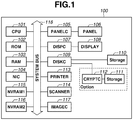
- Fig. 1 is a block diagram illustrating a configuration of an image forming apparatus according to a first exemplary embodiment of the present invention.
- the image forming apparatus According to the first exemplary embodiment, a description is given on the image forming apparatus as a data processing apparatus having a plurality of storage devices.
- the present invention can be applied to data processing apparatuses other than the image forming apparatus.
- an image forming apparatus 100 includes a CPU 101 that executes software stored in a read only memory (ROM) 102, a storage 110, or a storage 111.
- the image forming apparatus 100 processes various jobs in a plurality of operation modes.
- the type of job includes a print job, a copy job, and a data transfer job.
- the CPU 101 integrally controls devices connected to a system bus 118.
- a plurality of nonvolatile storage devices can be connected to the image forming apparatus 100.
- the storage 111 and an encryption controller (CRYPTC) 112 can be connected to the image forming apparatus 100.
- the storage 110 and the storage 111 are controlled in reading and writing by a disk controller 109.
- a description is given on a memory system in which the storage 110 includes a nonvolatile semiconductor storage device such as a solid state drive (SSD) and the storage 111 includes a nonvolatile storage device such as a hard disk drive (HDD) .
- a description is given by setting the storage 110 is first storage means and setting the storage 111 is second storage means.
- the storage 110 and the storage 111 are used also as a storage area for temporarily storing image data.
- the RAM 103 functions as a main memory or a work area of the CPU 101.
- An external input controller (PANELC) 105 controls an instruction input from various buttons or a touch panel 106 provided on the image forming apparatus 100.
- a display controller (DISPC) 107 controls the display of a display module (DISPLAY) 108 including a liquid crystal display.
- a network interface card (NIC) 104 interactively receives and transmits data from/to another network device or a file server.
- a printer 113 is configured by an electrophotographic or inkjet system, and prints data on a sheet.
- a scanner 114 reads an image printed on the sheet.
- an auto document feeder (not illustrated) is attached as an option to the scanner 114, and the scanner 114 automatically reads data on a plurality of documents conveyed by the auto document feeder.
- a nonvolatile RAM (NVRAM) 115 is a low speed nonvolatile memory with a medium size capacity, which stores various setting information and license information set to the image forming apparatus 100.
- a nonvolatile RAM (NVRAM) 116 is a high speed nonvolatile memory with a small capacity, which stores an activation mode and error information set to the image forming apparatus 100. The activation mode is specifically described below with reference to Fig. 4 .
- An image controller (IMAGEC) 117 processes image data on the RAM 103 in the image forming apparatus 100, and outputs the data to the RAM 103.
- Image processing includes processing such as rotation, zoom, color space conversion, gray-scale conversion, combination, coding, and decoding.
- Fig. 2 is a diagram illustrating a configuration of storage areas in the nonvolatile storage devices in Fig. 1 .
- the entire areas in the storages 110 and 111 are to be used, however, when the storage 111 exists, a part of the area in the storage 110 may not be used.
- An entire storage area 200 in the storage 110 is divided into a plurality of areas (partitions) and used according to purposes.
- the storage area 200 is divided into a program area 201, an expansion software storage area 202, an expansion software temporary storage area 203, an image data processing area 204, a user box area 205, and a log data storage area 206.
- An entire storage area 210 in the storage 111 is similarly divided into a plurality of areas (partitions) and used according to purposes.
- the entire storage area 210 is divided into an expansion program area 211, an expansion software storage area 212, an expansion print queue area 213, an expansion image data area 214, an expansion box area 215, and expansion log data storage area 216.
- the program area 201 and the expansion program area 211 store programs including an OS or resource data such as dictionaries or languages.
- the expansion software storage area 202 and the expansion software storage area 212 store software programs that realize additional functions.
- the program and software storage areas are used by the system and do not store user data.
- the expansion software temporary storage area 203 is for temporarily creating a file when executing the expansion software.
- the expansion print queue area 213 is for temporarily storing print data received by the network interface card (NIC) 104.
- NIC network interface card
- the image data processing area 204 and the expansion image data area 214 are for temporarily storing an image processing result of image data to be printed.
- the user box area 205 and the expansion box area 215 are for storing image data stored by the user.
- the log data storage area 206 and the expansion log data storage area 216 are for logging of a job status or a program operation status.
- the storages 110 and 111 are divided into the partitions according to purposes, and used.
- An area for storing data created by a user therein includes eight areas such as the expansion software temporary storage area 203, expansion print queue area 213, image data processing area 204, expansion image data area 214, user box area 205, expansion box area 215, log data storage area 206, and expansion log data storage area 216.
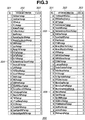
- Fig. 3 is a management table (license management table) stored in the nonvolatile RAM (NVRAM1) 115 in Fig. 1 .
- the NVRAM 115 stores, in nonvolatile manner, the following information as information indicating whether an option for encrypting data is valid or invalid when storing the data in the storage 111.
- the CPU 101 refers to the information according to a procedure in Fig. 6 , which will be described below.
- a management table 300 includes information such as a serial number 301, option information 302, and a status 303.
- the serial number 301 is just a serial number to be used for simply managing options .
- the option information (operation option) 302 is an ID for the management to identify the options.
- the status 303 is a flag indicating whether the option is validated and whether the image forming apparatus 100 is a model having a sufficient memory capacity or hardware for using the option, or a flag indicating whether the license of the option is validated. When the flag is "0", the status 303 indicates that the option is not operated. When the flag is "1”, the status 303 indicates that the option is operated or the license of the option is valid.
- the security operation means that the software encryption option 304 or the hardware encryption option 305 is valid.
- Fig. 4 is a diagram illustrating an activation mode of the image forming apparatus 100.
- a mode 401 is described as an example of a first operation mode
- a mode including the mode 403 is described as an example of a second operation mode.
- the mode 402 is described as an operation mode in which the storage 111 is available.
- the CPU 101 When activating the image forming apparatus 100, the CPU 101 refers to the nonvolatile RAM (NVRAM) 116 to determine the activation mode. If the activation is suspended until ending the initialization of the license information or the hardware, the activation time period is prolonged and the operability or usability of the user deteriorates. Therefore, the activation mode is determined by referring to the NVRAM 116.
- the NVRAM 116 stores activation mode information indicating one of the modes 401 to 404 illustrated in Fig. 4 .
- the CPU 101 After normally activating the image forming apparatus 100, the CPU 101 reads the information in the NVRAM 115, and sets the activation mode information for the next activation in advance.
- the activation mode information indicates a default mode (e.g., mode 401 or mode 402) according to the status of the option.
- the mode 401 is a FLASH normal mode in which only the storage 110 including the SSD is used to be operated in the present exemplary embodiment.
- the image forming apparatus 100 uses only the storage 110 as the system area and the data area.
- the CPU 101 performs the activation processing by assuming that there is not the storage 111.
- data of image data or user setting is stored only in the storage 110.
- the mode 402 is an HDD normal mode.
- the operation is performed by using both the storage 110 including the SSD and the storage 111 including the HDD.
- the activation mode is switched from the mode 401 to the mode 402. Then, the image forming apparatus 100 is activated in the HDD normal mode for the next activation time.
- the image forming apparatus 100 uses the storage 110 as the system area, and further uses the storage 111 as the data area. In this case, data requiring security management such as image data or a user setting is stored only in the storage 111.
- the mode 403 is an HDD failure mode.
- the operation is performed by using only the storage 110 including the SSD, and the storage 111 including the HDD is detected but is not used.
- the activation mode is switched from the mode 402 to the mode 403. Then, the image forming apparatus 100 is activated in the mode 403 for the next activation time. In this case, the image forming apparatus 100 uses the storage 110 as the system area and the data area.
- an HDD error screen is displayed on the touch panel 106 to control the operation so that the user cannot create and update the data.
- the processing is an example of the degeneration processing.
- a service engineer performs recovery operation of the HDD corresponding to the storage 111, thereby returning the activation mode to the HDD normal mode.
- the user can select the activation in the mode 401.
- the selection is described below.
- the mode 404 is an operation limit mode. In the mode 404, the operation is performed by using only the storage 110 including the SSD. The user operates a button displayed on the touch panel 106, thereby selecting the activation in the mode 404. In the mode 404, the image forming apparatus 100 is operated by using only the storage 110 including the SSD as the system area and the data area, and the data area in the SSD is not updated.
- the CPU 101 is activated in a status in which the operation is limited so that no operations for updating the data area in the storage 110 are selectable by the user. This is also an example of the degeneration processing.
- the CPU 101 controls an image storage button, a copy-number setting button, a sort setting button, storage image operation buttons, and an operation screen of change of setting, and an operation screen of held jobs, to be gray-out or non-displayed.
- the operation limit mode is specifically described in a second exemplary embodiment.
- the activation mode determination processing is described with reference to a flowchart in Fig. 5 .
- the activation mode determination processing is executed just before ending the operation of the image forming apparatus 100.
- Fig. 5 is a flowchart illustrating a control procedure of the image forming apparatus according to the present exemplary embodiment.
- the example corresponds to the outline of a flow of the activation mode determination processing. Steps are realized by the CPU 101 loading a control program to the RAM 103 and realizing the loaded program.
- step S501 the CPU 101 performs abnormality detection processing to specify an option to be stopped.
- the CPU 101 specifies an option relating to the HDD option and sets the specified option as a stop target.
- step S502 the CPU 101 acquires security option information from the NVRAM 115 to specify the operation of the storage 111 or encryption controller 112.
- the security option information includes the software encryption option 304 and the hardware encryption option 305.
- step S503 the CPU 101 determines whether the abnormality is detected in step S501. When the abnormality is detected (YES in step S503), the processing proceeds to step S504. In step S504, the CPU 101 performs activation mode updating processing for updating the activation mode for the next activation time according to the abnormality detected in step S501 and the security option information obtained in step S502. Thus, the activation mode information in the NVRAM 116 is updated.
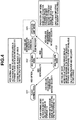
- Fig. 6 is a flowchart illustrating a control procedure of the image forming apparatus according to the present exemplary embodiment. Steps are realized by the CPU 101 loading a control program to the RAM 103 and executing the loaded program.
- step S601 the CPU 101 determines, based on the abnormality detected in step S501, whether the generated abnormality relates to the HDD and/or encryption device.
- the CPU 101 determines that the generated abnormality does not relate to the HDD and/or encryption device (NO in step S601), the CPU 101 ends the processing without updating the activation mode.
- step S601 the CPU 101 determines that the generated abnormality relates to the HDD and/or encryption device (YES in step S601), the CPU 101 proceeds to step S602. In step S602, the CPU 101 determines, based on the security option information acquired in step S502, whether the security license is valid.
- the CPU 101 determines that the security license is valid.
- the CPU 101 determines that the security license is not valid (NO in step S602), the CPU 101 determines that the activation mode can be changed to the FLASH normal mode (corresponding to the mode 401 in Fig. 4 ), the processing proceeds to step S605.
- step S603 the CPU 101 acquires various settings on the security from the NVRAM 115.
- Various settings on the security include information indicating whether the encryption is actually used, e.g., whether an encryption key is generated, whether a data target to be encrypted exists, whether the number of records of the encrypted data is 1 or more, whether an encryption system is other than through-setting.
- step S604 the CPU 101 determines from the information acquired in step S603, whether the encryption license is actually operated.
- the CPU 101 determines that the encryption license is actually operated (YES in step S604), in S606, the CPU 101 stores information indicating that degeneration is not instructed in the NVRAM 116. Then, the CPU 101 ends the operation mode determination processing.
- the mode is switched to the FLASH normal mode, thereby reducing the security level. Therefore, the degeneration to the FLASH normal mode is not performed.
- the CPU 101 changes the activation mode indicated by the activation mode information in the NVRAM 116 to the HDD failure mode (the mode 403 in Fig. 4 ) .
- the CPU 101 displays an error screen (not illustrated) indicating an error of the HDD or encryption device on the touch panel 106, and maintains the current status until the service engineer ends the recovery of the HDD.
- step S604 When the CPU 101 determines that the encryption license is not operated (NO in step S604), the CPU 101 determines that the operation mode can be changed to the FLASH normal mode (the mode 401 illustrated in Fig. 4 ). Then, the processing proceeds to step S605. In other words, when the CPU 101 determines in step S602 that the security license is invalid or in step S604 that the encryption license is not operated, the processing proceeds to step S605.
- step S605 the CPU 101 determines that the mode can be switched to the FLASH normal mode (the mode 401 illustrated in Fig. 4 ), and displays a change button for shifting to the degeneration operation without using the HDD on the touch panel 106 (hereinafter, change button).
- change button a change button for shifting to the degeneration operation without using the HDD on the touch panel 106
- an error screen illustrating an error of the HDD or encryption device and the change button are displayed on the touch panel 106 of the image forming apparatus 100 (not illustrated).
- step S607 the CPU 101 determines whether the user presses the change button.
- the CPU 101 determines that the user presses the change button (YES in step S607)
- step S608 the CPU 101 changes the activation mode indicated by the activation mode information in the NVRAM 116 to the HDD failure mode, and stores information in the NVRAM 116 indicating that the degeneration is instructed.
- step S606 the CPU 101 changes the activation mode indicated by the activation mode information in the NVRAM 116 to the HDD failure mode, and stores information in the NVRAM 116 indicating that the degeneration is not instructed.
- step S606 or S608 When step S606 or S608 is not executed, the activation mode is not changed and the activation mode information stored in the NVRAM 116 indicates the FLASH normal mode or the HDD normal mode.
- Fig. 7 illustrates a control procedure of the image forming apparatus according to the present exemplary embodiment. Steps are realized by the CPU 101 loading a control program to the RAM 103 and executing the loaded program. When activating the image forming apparatus 100, the CPU 101 refers to the activation mode information in the NVRAM 116 to determine a storage device necessary at the activation time.
- step S701 the CPU 101 reads the activation mode information in the NVRAM 116, and determines whether the activation mode is the mode (HDD normal mode or HDD failure mode) to use the HDD.
- the mode not to use the HDD is operated by using only the storage 110, and the mode to use the HDD is operated by using the storage 111.
- step S708 the CPU 101 determines that the activation mode is the FLASH normal mode (the mode 401 in Fig. 4 ), and then ends the determination processing.
- step S702 the CPU 101 determines whether the activation mode is the HDD failure mode (the mode 403 illustrated in Fig. 4 ).
- step S703 the CPU 101 executes processing for determining whether the abnormality of the HDD currently continues .
- step S703 the CPU 101 determines that the activation mode is not the HDD failure mode.
- the processing for determining whether the abnormality of the HDD continues in step S703 includes detection of a block device, detection of an abnormality of a file system, mount test processing, and file read/write test processing. Further, the processing may include determination processing of file generation/deletion test processing and acquisition of self-monitoring, analysis, and reporting technology (SMART) information.
- SMART self-monitoring, analysis, and reporting technology
- step S704 the CPU 101 determines based on the determination processing executed in step S703, whether the HDD has been recovered.
- the CPU 101 determines that the test performed in step S703 passes without fails, the CPU 101 determines that the HDD is recovered from the abnormality.
- step S707 the CPU 101 determines that the activation mode is the HDD normal mode (the mode 402 in Fig. 4 ), and ends the activation mode determination processing.
- step S705 the CPU 101 determines whether the degeneration is instructed. That is, the CPU 101 determines whether information indicating that the degeneration is instructed is stored in the NVRAM 116.
- step S709 the CPU 101 determines that the activation mode is the HDD failure mode (the mode 403 illustrated in Fig. 4 ), and ends the activation mode determination processing.
- step S705 when the CPU 101 determines that the degeneration is instructed (YES in step S705), in step S706, the CPU 101 determines that the activation mode is the FLASH normal mode (the mode 401 illustrated in Fig. 4 ), and ends the activation mode determination processing.
- the image forming apparatus 100 is activated in the determined activation mode.
- the degeneration processing is properly executed according to whether or not the security operation is performed.
- the image forming apparatus 100 is controlled to prevent the execution of data processing until the recovery of the HDD. Even if the SSD is detached, it is possible to prevent the user information stored in the SSD from being sneaked by the third party.
- the case of changing the operation mode to the FLASH normal mode in step S706 when the CPU 101 determines that the degeneration is instructed is described. Further, according to the first exemplary embodiment, the case of changing the activation mode to the HDD failure mode when the encryption license is operated, is described.
- the activation mode can be changed to the operation limit mode.
- the user can use the image forming apparatus 100 within a range for keeping the security to some degree.
- the flowchart illustrated in Fig. 6 is changed as follows.
- the CPU 101 determines that the encryption license is operated (YES in step S604)
- the CPU 101 displays the change button on the touch panel 106.
- the change button YES in step S607
- the CPU 101 changes the activation mode indicated by the activation mode information stored in the NVRAM 116 to the HDD failure mode, and stores information indicating that the degeneration is instructed (degeneration is performed) and information indicating that the degeneration to the operation limit mode is performed in the NVRAM 116.
- the CPU 101 changes the activation mode indicated by the activation mode information in the NVRAM 116 to the HDD failure mode, and stores information indicating that the degeneration is not instructed (degeneration is not performed) to the NVRAM 116.
- the image forming apparatus 100 executes the activation mode determination processing in Fig. 8 .
- Fig. 8 is a flowchart illustrating a control procedure of an image forming apparatus according to the present exemplary embodiment. Steps are realized by the CPU 101 loading the control program to the RAM 103 and executing the loaded program. When the image forming apparatus 100 is activated, as described above, the CPU 101 refers to the activation mode stored in the NVRAM 116 to determine a storage device required for the activation.
- step S801 the CPU 101 determines whether the degeneration to the operation limit mode is performed. In other words, the CPU 101 determines that information indicating the degeneration to the operation limit mode is stored in the NVRAM 116.
- step S706 the CPU 101 determines that the activation mode is the FLASH normal mode (the mode 401 illustrated in Fig. 4 ).
- step S802 the CPU 101 determines that the activation mode is the operation limit mode (the mode 404 illustrated in Fig. 4 ).
- Fig. 9 is a flowchart of a control procedure of the image forming apparatus 100 according to the present exemplary embodiment.
- An example in Fig. 9 corresponds to the outline of display limit processing in the operation limit mode. Steps are realized by the CPU 101 loading the control program to the RAM 103 and executing the loaded program.
- the image forming apparatus 100 is activated in the operation limit mode.
- step S901 the CPU 101 executes the display limit processing.
- the display limit processing includes non-display processing of an image storage button, a copy-number designation button, a sort designation button, buttons relating to storage image operation, a setting change button, and buttons relating to a nonvolatile job.
- the nonvolatile job includes a transmission job and a reservation job with a timer.
- step S902 the CPU 101 sets non-limit to a start timer for setting an output start time (output start time to secondary storage) to the storage 110, and ends the present processing. According to this, an output of the image data on the RAM 103 to the storage 110 is not performed even if the printer 113 does not obtain the image data from the RAM 103 for a long time.
- the scanner 114 reads the document, or the NIC 104 receives PDL data. Then, the image data stored in the RAM 103 is processed via the image processing controller 117 as follows. Specifically, the CPU 101 controls the operation to prevent an output of the image data on the RAM 103 to the storage 110 even if it takes a predetermined time to obtain data by the printer 113.
- the deterioration of security level is prevented even if the storage device involved in the security operation is in trouble. Further, with the determination of any of the activation modes, a user-available degeneration function can be selected.
- the execution of operation mode can be switched according to the option status.
- aspects of the present invention can also be realized by a computer of a system or apparatus (or devices such as a CPU or MPU) that reads out and executes a program recorded on a memory device to perform the functions of the above-described embodiments, and by a method, the steps of which are performed by a computer of a system or apparatus by, for example, reading out and executing a program recorded on a memory device to perform the functions of the above-described embodiments.
- the program is provided to the computer for example via a network or from a recording medium of various types serving as the memory device (e.g., computer-readable medium) .
- the system or apparatus, and the recording medium where the program is stored are included as being within the scope of the present invention.
Landscapes
- Engineering & Computer Science (AREA)
- Computer Security & Cryptography (AREA)
- Computer Hardware Design (AREA)
- Theoretical Computer Science (AREA)
- Software Systems (AREA)
- Physics & Mathematics (AREA)
- General Engineering & Computer Science (AREA)
- General Physics & Mathematics (AREA)
- Facsimiles In General (AREA)
- Storage Device Security (AREA)
- Techniques For Improving Reliability Of Storages (AREA)
Applications Claiming Priority (1)
| Application Number | Priority Date | Filing Date | Title |
|---|---|---|---|
| JP2010145144A JP5506568B2 (ja) | 2010-06-25 | 2010-06-25 | データ処理装置、データ処理装置のデータ処理方法、プログラム |
Publications (2)
| Publication Number | Publication Date |
|---|---|
| EP2400423A1 EP2400423A1 (en) | 2011-12-28 |
| EP2400423B1 true EP2400423B1 (en) | 2019-04-17 |
Family
ID=44645345
Family Applications (1)
| Application Number | Title | Priority Date | Filing Date |
|---|---|---|---|
| EP11168958.4A Not-in-force EP2400423B1 (en) | 2010-06-25 | 2011-06-07 | Data processing apparatus and data processing method of data processing apparatus |
Country Status (4)
| Country | Link |
|---|---|
| US (1) | US8458423B2 (enExample) |
| EP (1) | EP2400423B1 (enExample) |
| JP (1) | JP5506568B2 (enExample) |
| CN (1) | CN102394996B (enExample) |
Families Citing this family (11)
| Publication number | Priority date | Publication date | Assignee | Title |
|---|---|---|---|---|
| JP5787616B2 (ja) * | 2011-05-20 | 2015-09-30 | キヤノン株式会社 | 画像処理装置、画像処理装置の制御方法及びプログラム |
| JP2013250690A (ja) * | 2012-05-31 | 2013-12-12 | Renesas Electronics Corp | データ処理装置、マイクロコントローラ、およびデータ処理装置の自己診断方法 |
| JP5825290B2 (ja) * | 2013-04-08 | 2015-12-02 | コニカミノルタ株式会社 | 画像形成装置 |
| JP5986963B2 (ja) * | 2013-07-08 | 2016-09-06 | 京セラドキュメントソリューションズ株式会社 | 画像読取装置及びこれを備えた画像形成装置 |
| JP2015211256A (ja) * | 2014-04-24 | 2015-11-24 | キヤノン株式会社 | 情報処理装置、情報処理方法、およびプログラム |
| JP6292085B2 (ja) * | 2014-08-28 | 2018-03-14 | 京セラドキュメントソリューションズ株式会社 | 電子機器、及び画像形成装置 |
| JP6376472B2 (ja) | 2015-10-20 | 2018-08-22 | 京セラドキュメントソリューションズ株式会社 | 画像形成装置及びプログラム |
| JP6376146B2 (ja) * | 2016-01-27 | 2018-08-22 | 京セラドキュメントソリューションズ株式会社 | 画像形成装置およびデータ処理プログラム |
| JP6410055B2 (ja) * | 2016-01-27 | 2018-10-24 | 京セラドキュメントソリューションズ株式会社 | 画像形成装置およびデータ処理プログラム |
| JP7275922B2 (ja) * | 2019-06-28 | 2023-05-18 | 沖電気工業株式会社 | 情報処理装置、異常検出方法及びプログラム |
| JP2024101639A (ja) * | 2023-01-18 | 2024-07-30 | キヤノン株式会社 | 情報処理装置および情報処理装置の制御方法 |
Citations (1)
| Publication number | Priority date | Publication date | Assignee | Title |
|---|---|---|---|---|
| EP2026538A1 (en) * | 2007-08-15 | 2009-02-18 | Hitachi, Ltd. | System and method for data protection management for network storage |
Family Cites Families (17)
| Publication number | Priority date | Publication date | Assignee | Title |
|---|---|---|---|---|
| JP2002024092A (ja) * | 2000-07-03 | 2002-01-25 | Hitachi Ltd | 著作権保護機能を具備した情報記録再生装置 |
| AUPQ866000A0 (en) * | 2000-07-07 | 2000-08-03 | Activesky, Inc. | A secure data storage device |
| CN100508452C (zh) * | 2002-04-17 | 2009-07-01 | 松下电器产业株式会社 | 信息输入/输出以及密钥管理的系统和装置 |
| CN100552690C (zh) * | 2004-07-05 | 2009-10-21 | 科学园株式会社 | 数据管理方法 |
| US8112601B2 (en) * | 2004-08-09 | 2012-02-07 | Jasim Saleh Al-Azzawi | Data storage device with security feature |
| EP1825676A1 (en) * | 2004-12-06 | 2007-08-29 | Koninklijke Philips Electronics N.V. | Method and apparatus for utilizing a broadcast flag |
| JP4842593B2 (ja) * | 2005-09-05 | 2011-12-21 | 株式会社日立製作所 | ストレージ仮想化装置のデバイス制御引継ぎ方法 |
| JP2007207139A (ja) * | 2006-02-06 | 2007-08-16 | Toshiba Tec Corp | 情報処理装置 |
| JP2008148226A (ja) | 2006-12-13 | 2008-06-26 | Canon Inc | Hdd自己診断機能を利用した縮退動作を行う画像形成装置 |
| US8010768B2 (en) * | 2007-05-09 | 2011-08-30 | Kingston Technology Corporation | Secure and scalable solid state disk system |
| JP2009025928A (ja) * | 2007-07-18 | 2009-02-05 | Konica Minolta Business Technologies Inc | 暗号化データ処理方法及び暗号化データ処理プログラム並びに暗号化データ処理装置 |
| JP4990089B2 (ja) * | 2007-10-12 | 2012-08-01 | 株式会社日立製作所 | 格納データ暗号化機能内蔵ストレージ装置の暗号鍵をバックアップ及びリストアする計算機システム |
| JP5266713B2 (ja) * | 2007-10-23 | 2013-08-21 | 日本電気株式会社 | 情報処理装置、プログラム、外部暗号化システム、及び、外部暗号化方法 |
| US9134917B2 (en) * | 2008-02-12 | 2015-09-15 | Netapp, Inc. | Hybrid media storage system architecture |
| JP4999736B2 (ja) * | 2008-03-13 | 2012-08-15 | キヤノン株式会社 | データ処理装置 |
| JP2010009553A (ja) * | 2008-06-30 | 2010-01-14 | Ricoh Co Ltd | 情報処理装置、情報処理方法、及び情報処理プログラム |
| US8539245B2 (en) * | 2010-08-06 | 2013-09-17 | Intel Corporation | Apparatus and method for accessing a secure partition in non-volatile storage by a host system enabled after the system exits a first instance of a secure mode |
-
2010
- 2010-06-25 JP JP2010145144A patent/JP5506568B2/ja active Active
-
2011
- 2011-06-07 EP EP11168958.4A patent/EP2400423B1/en not_active Not-in-force
- 2011-06-20 US US13/164,264 patent/US8458423B2/en not_active Expired - Fee Related
- 2011-06-24 CN CN201110175787.1A patent/CN102394996B/zh not_active Expired - Fee Related
Patent Citations (1)
| Publication number | Priority date | Publication date | Assignee | Title |
|---|---|---|---|---|
| EP2026538A1 (en) * | 2007-08-15 | 2009-02-18 | Hitachi, Ltd. | System and method for data protection management for network storage |
Also Published As
| Publication number | Publication date |
|---|---|
| CN102394996A (zh) | 2012-03-28 |
| CN102394996B (zh) | 2015-07-08 |
| US8458423B2 (en) | 2013-06-04 |
| US20110320748A1 (en) | 2011-12-29 |
| EP2400423A1 (en) | 2011-12-28 |
| JP2012008861A (ja) | 2012-01-12 |
| JP5506568B2 (ja) | 2014-05-28 |
Similar Documents
| Publication | Publication Date | Title |
|---|---|---|
| EP2400423B1 (en) | Data processing apparatus and data processing method of data processing apparatus | |
| US11204852B2 (en) | Information processing apparatus, method of controlling the same, information processing system and storage medium | |
| KR102096688B1 (ko) | 인쇄 장치, 인쇄 장치의 제어 방법 및 저장 매체 | |
| US9361472B2 (en) | Information processing apparatus, control method of information processing apparatus, and program | |
| JP2008012868A (ja) | 記録装置、情報処理装置及びそれらの制御方法、記録システム、プログラム | |
| JP4386289B2 (ja) | コンピュータプログラム、画像形成装置、画像形成装置の制御方法 | |
| JP4836083B2 (ja) | 画像形成装置、画像形成装置の制御方法、及びコンピュータプログラム | |
| KR102180024B1 (ko) | 인쇄 장치 및 인쇄 장치 제어 방법 | |
| US20180272733A1 (en) | Device, method for controlling device, and storage medium | |
| US8699069B2 (en) | Information processing apparatus, information processing method, and storage medium for processing job data stored in a folder | |
| JP7071549B2 (ja) | 印刷装置、印刷装置の制御方法、及びプログラム | |
| KR101623625B1 (ko) | 덮어쓰기 기능을 가진 정보 처리 장치, 그 제어 방법 및 기억 매체 | |
| US8689320B2 (en) | Image forming apparatus with hard disk drive securely formatted | |
| KR102278901B1 (ko) | 화상 형성 장치, 그 제어 방법, 및 기억 매체 | |
| JP5215802B2 (ja) | 印刷装置 | |
| JP4830968B2 (ja) | 印刷システム、印刷制御装置、印刷システムの制御方法、ドライバプログラム、およびそのプログラムを記録した記録媒体 | |
| JP4478644B2 (ja) | 印刷装置及び処理方法及びプログラム並びに記憶媒体 | |
| JP7596793B2 (ja) | 画像形成装置 | |
| JP7639346B2 (ja) | 画像形成装置 | |
| JP2024101639A (ja) | 情報処理装置および情報処理装置の制御方法 | |
| JP2024029496A (ja) | 画像処理装置、制御方法、及びコンピュータプログラム | |
| US20110055508A1 (en) | Information processing apparatus, data transfer method, and computer-readable recording medium | |
| JP2018124611A (ja) | 外部メディア処理装置およびプログラム | |
| JP6673025B2 (ja) | 情報処理装置およびプログラム | |
| JP2017017464A (ja) | 情報処理装置及びアプリケーションプログラムのバックアップ・レストア方法 |
Legal Events
| Date | Code | Title | Description |
|---|---|---|---|
| AK | Designated contracting states |
Kind code of ref document: A1 Designated state(s): AL AT BE BG CH CY CZ DE DK EE ES FI FR GB GR HR HU IE IS IT LI LT LU LV MC MK MT NL NO PL PT RO RS SE SI SK SM TR |
|
| AX | Request for extension of the european patent |
Extension state: BA ME |
|
| PUAI | Public reference made under article 153(3) epc to a published international application that has entered the european phase |
Free format text: ORIGINAL CODE: 0009012 |
|
| 17P | Request for examination filed |
Effective date: 20120628 |
|
| 17Q | First examination report despatched |
Effective date: 20140620 |
|
| STAA | Information on the status of an ep patent application or granted ep patent |
Free format text: STATUS: EXAMINATION IS IN PROGRESS |
|
| REG | Reference to a national code |
Ref country code: DE Ref legal event code: R079 Ref document number: 602011058087 Country of ref document: DE Free format text: PREVIOUS MAIN CLASS: G06F0021000000 Ipc: G06F0021780000 |
|
| GRAP | Despatch of communication of intention to grant a patent |
Free format text: ORIGINAL CODE: EPIDOSNIGR1 |
|
| STAA | Information on the status of an ep patent application or granted ep patent |
Free format text: STATUS: GRANT OF PATENT IS INTENDED |
|
| RIC1 | Information provided on ipc code assigned before grant |
Ipc: G06F 21/78 20111228AFI20181018BHEP |
|
| INTG | Intention to grant announced |
Effective date: 20181108 |
|
| RIC1 | Information provided on ipc code assigned before grant |
Ipc: G06F 21/78 20130101AFI20181018BHEP |
|
| RIC1 | Information provided on ipc code assigned before grant |
Ipc: G06F 21/78 20130101AFI20181018BHEP |
|
| GRAS | Grant fee paid |
Free format text: ORIGINAL CODE: EPIDOSNIGR3 |
|
| GRAA | (expected) grant |
Free format text: ORIGINAL CODE: 0009210 |
|
| STAA | Information on the status of an ep patent application or granted ep patent |
Free format text: STATUS: THE PATENT HAS BEEN GRANTED |
|
| AK | Designated contracting states |
Kind code of ref document: B1 Designated state(s): AL AT BE BG CH CY CZ DE DK EE ES FI FR GB GR HR HU IE IS IT LI LT LU LV MC MK MT NL NO PL PT RO RS SE SI SK SM TR |
|
| REG | Reference to a national code |
Ref country code: GB Ref legal event code: FG4D |
|
| REG | Reference to a national code |
Ref country code: CH Ref legal event code: EP |
|
| REG | Reference to a national code |
Ref country code: DE Ref legal event code: R096 Ref document number: 602011058087 Country of ref document: DE |
|
| REG | Reference to a national code |
Ref country code: AT Ref legal event code: REF Ref document number: 1122369 Country of ref document: AT Kind code of ref document: T Effective date: 20190515 Ref country code: IE Ref legal event code: FG4D |
|
| REG | Reference to a national code |
Ref country code: NL Ref legal event code: MP Effective date: 20190417 |
|
| REG | Reference to a national code |
Ref country code: LT Ref legal event code: MG4D |
|
| PG25 | Lapsed in a contracting state [announced via postgrant information from national office to epo] |
Ref country code: NL Free format text: LAPSE BECAUSE OF FAILURE TO SUBMIT A TRANSLATION OF THE DESCRIPTION OR TO PAY THE FEE WITHIN THE PRESCRIBED TIME-LIMIT Effective date: 20190417 |
|
| PG25 | Lapsed in a contracting state [announced via postgrant information from national office to epo] |
Ref country code: FI Free format text: LAPSE BECAUSE OF FAILURE TO SUBMIT A TRANSLATION OF THE DESCRIPTION OR TO PAY THE FEE WITHIN THE PRESCRIBED TIME-LIMIT Effective date: 20190417 Ref country code: NO Free format text: LAPSE BECAUSE OF FAILURE TO SUBMIT A TRANSLATION OF THE DESCRIPTION OR TO PAY THE FEE WITHIN THE PRESCRIBED TIME-LIMIT Effective date: 20190717 Ref country code: SE Free format text: LAPSE BECAUSE OF FAILURE TO SUBMIT A TRANSLATION OF THE DESCRIPTION OR TO PAY THE FEE WITHIN THE PRESCRIBED TIME-LIMIT Effective date: 20190417 Ref country code: PT Free format text: LAPSE BECAUSE OF FAILURE TO SUBMIT A TRANSLATION OF THE DESCRIPTION OR TO PAY THE FEE WITHIN THE PRESCRIBED TIME-LIMIT Effective date: 20190817 Ref country code: AL Free format text: LAPSE BECAUSE OF FAILURE TO SUBMIT A TRANSLATION OF THE DESCRIPTION OR TO PAY THE FEE WITHIN THE PRESCRIBED TIME-LIMIT Effective date: 20190417 Ref country code: LT Free format text: LAPSE BECAUSE OF FAILURE TO SUBMIT A TRANSLATION OF THE DESCRIPTION OR TO PAY THE FEE WITHIN THE PRESCRIBED TIME-LIMIT Effective date: 20190417 Ref country code: ES Free format text: LAPSE BECAUSE OF FAILURE TO SUBMIT A TRANSLATION OF THE DESCRIPTION OR TO PAY THE FEE WITHIN THE PRESCRIBED TIME-LIMIT Effective date: 20190417 Ref country code: HR Free format text: LAPSE BECAUSE OF FAILURE TO SUBMIT A TRANSLATION OF THE DESCRIPTION OR TO PAY THE FEE WITHIN THE PRESCRIBED TIME-LIMIT Effective date: 20190417 |
|
| PGFP | Annual fee paid to national office [announced via postgrant information from national office to epo] |
Ref country code: DE Payment date: 20190830 Year of fee payment: 9 |
|
| PG25 | Lapsed in a contracting state [announced via postgrant information from national office to epo] |
Ref country code: GR Free format text: LAPSE BECAUSE OF FAILURE TO SUBMIT A TRANSLATION OF THE DESCRIPTION OR TO PAY THE FEE WITHIN THE PRESCRIBED TIME-LIMIT Effective date: 20190718 Ref country code: BG Free format text: LAPSE BECAUSE OF FAILURE TO SUBMIT A TRANSLATION OF THE DESCRIPTION OR TO PAY THE FEE WITHIN THE PRESCRIBED TIME-LIMIT Effective date: 20190717 Ref country code: PL Free format text: LAPSE BECAUSE OF FAILURE TO SUBMIT A TRANSLATION OF THE DESCRIPTION OR TO PAY THE FEE WITHIN THE PRESCRIBED TIME-LIMIT Effective date: 20190417 Ref country code: LV Free format text: LAPSE BECAUSE OF FAILURE TO SUBMIT A TRANSLATION OF THE DESCRIPTION OR TO PAY THE FEE WITHIN THE PRESCRIBED TIME-LIMIT Effective date: 20190417 Ref country code: RS Free format text: LAPSE BECAUSE OF FAILURE TO SUBMIT A TRANSLATION OF THE DESCRIPTION OR TO PAY THE FEE WITHIN THE PRESCRIBED TIME-LIMIT Effective date: 20190417 |
|
| REG | Reference to a national code |
Ref country code: AT Ref legal event code: MK05 Ref document number: 1122369 Country of ref document: AT Kind code of ref document: T Effective date: 20190417 |
|
| PG25 | Lapsed in a contracting state [announced via postgrant information from national office to epo] |
Ref country code: IS Free format text: LAPSE BECAUSE OF FAILURE TO SUBMIT A TRANSLATION OF THE DESCRIPTION OR TO PAY THE FEE WITHIN THE PRESCRIBED TIME-LIMIT Effective date: 20190817 |
|
| REG | Reference to a national code |
Ref country code: DE Ref legal event code: R097 Ref document number: 602011058087 Country of ref document: DE |
|
| PG25 | Lapsed in a contracting state [announced via postgrant information from national office to epo] |
Ref country code: CZ Free format text: LAPSE BECAUSE OF FAILURE TO SUBMIT A TRANSLATION OF THE DESCRIPTION OR TO PAY THE FEE WITHIN THE PRESCRIBED TIME-LIMIT Effective date: 20190417 Ref country code: RO Free format text: LAPSE BECAUSE OF FAILURE TO SUBMIT A TRANSLATION OF THE DESCRIPTION OR TO PAY THE FEE WITHIN THE PRESCRIBED TIME-LIMIT Effective date: 20190417 Ref country code: AT Free format text: LAPSE BECAUSE OF FAILURE TO SUBMIT A TRANSLATION OF THE DESCRIPTION OR TO PAY THE FEE WITHIN THE PRESCRIBED TIME-LIMIT Effective date: 20190417 Ref country code: EE Free format text: LAPSE BECAUSE OF FAILURE TO SUBMIT A TRANSLATION OF THE DESCRIPTION OR TO PAY THE FEE WITHIN THE PRESCRIBED TIME-LIMIT Effective date: 20190417 Ref country code: DK Free format text: LAPSE BECAUSE OF FAILURE TO SUBMIT A TRANSLATION OF THE DESCRIPTION OR TO PAY THE FEE WITHIN THE PRESCRIBED TIME-LIMIT Effective date: 20190417 Ref country code: SK Free format text: LAPSE BECAUSE OF FAILURE TO SUBMIT A TRANSLATION OF THE DESCRIPTION OR TO PAY THE FEE WITHIN THE PRESCRIBED TIME-LIMIT Effective date: 20190417 Ref country code: MC Free format text: LAPSE BECAUSE OF FAILURE TO SUBMIT A TRANSLATION OF THE DESCRIPTION OR TO PAY THE FEE WITHIN THE PRESCRIBED TIME-LIMIT Effective date: 20190417 |
|
| REG | Reference to a national code |
Ref country code: CH Ref legal event code: PL |
|
| PLBE | No opposition filed within time limit |
Free format text: ORIGINAL CODE: 0009261 |
|
| STAA | Information on the status of an ep patent application or granted ep patent |
Free format text: STATUS: NO OPPOSITION FILED WITHIN TIME LIMIT |
|
| PG25 | Lapsed in a contracting state [announced via postgrant information from national office to epo] |
Ref country code: IT Free format text: LAPSE BECAUSE OF FAILURE TO SUBMIT A TRANSLATION OF THE DESCRIPTION OR TO PAY THE FEE WITHIN THE PRESCRIBED TIME-LIMIT Effective date: 20190417 Ref country code: SM Free format text: LAPSE BECAUSE OF FAILURE TO SUBMIT A TRANSLATION OF THE DESCRIPTION OR TO PAY THE FEE WITHIN THE PRESCRIBED TIME-LIMIT Effective date: 20190417 |
|
| 26N | No opposition filed |
Effective date: 20200120 |
|
| GBPC | Gb: european patent ceased through non-payment of renewal fee |
Effective date: 20190717 |
|
| REG | Reference to a national code |
Ref country code: BE Ref legal event code: MM Effective date: 20190630 |
|
| PG25 | Lapsed in a contracting state [announced via postgrant information from national office to epo] |
Ref country code: TR Free format text: LAPSE BECAUSE OF FAILURE TO SUBMIT A TRANSLATION OF THE DESCRIPTION OR TO PAY THE FEE WITHIN THE PRESCRIBED TIME-LIMIT Effective date: 20190417 |
|
| PG25 | Lapsed in a contracting state [announced via postgrant information from national office to epo] |
Ref country code: GB Free format text: LAPSE BECAUSE OF NON-PAYMENT OF DUE FEES Effective date: 20190717 Ref country code: IE Free format text: LAPSE BECAUSE OF NON-PAYMENT OF DUE FEES Effective date: 20190607 |
|
| PG25 | Lapsed in a contracting state [announced via postgrant information from national office to epo] |
Ref country code: SI Free format text: LAPSE BECAUSE OF FAILURE TO SUBMIT A TRANSLATION OF THE DESCRIPTION OR TO PAY THE FEE WITHIN THE PRESCRIBED TIME-LIMIT Effective date: 20190417 Ref country code: BE Free format text: LAPSE BECAUSE OF NON-PAYMENT OF DUE FEES Effective date: 20190630 Ref country code: LU Free format text: LAPSE BECAUSE OF NON-PAYMENT OF DUE FEES Effective date: 20190607 Ref country code: LI Free format text: LAPSE BECAUSE OF NON-PAYMENT OF DUE FEES Effective date: 20190630 Ref country code: CH Free format text: LAPSE BECAUSE OF NON-PAYMENT OF DUE FEES Effective date: 20190630 |
|
| PG25 | Lapsed in a contracting state [announced via postgrant information from national office to epo] |
Ref country code: FR Free format text: LAPSE BECAUSE OF NON-PAYMENT OF DUE FEES Effective date: 20190617 |
|
| REG | Reference to a national code |
Ref country code: DE Ref legal event code: R119 Ref document number: 602011058087 Country of ref document: DE |
|
| PG25 | Lapsed in a contracting state [announced via postgrant information from national office to epo] |
Ref country code: DE Free format text: LAPSE BECAUSE OF NON-PAYMENT OF DUE FEES Effective date: 20210101 Ref country code: CY Free format text: LAPSE BECAUSE OF FAILURE TO SUBMIT A TRANSLATION OF THE DESCRIPTION OR TO PAY THE FEE WITHIN THE PRESCRIBED TIME-LIMIT Effective date: 20190417 |
|
| PG25 | Lapsed in a contracting state [announced via postgrant information from national office to epo] |
Ref country code: HU Free format text: LAPSE BECAUSE OF FAILURE TO SUBMIT A TRANSLATION OF THE DESCRIPTION OR TO PAY THE FEE WITHIN THE PRESCRIBED TIME-LIMIT; INVALID AB INITIO Effective date: 20110607 Ref country code: MT Free format text: LAPSE BECAUSE OF FAILURE TO SUBMIT A TRANSLATION OF THE DESCRIPTION OR TO PAY THE FEE WITHIN THE PRESCRIBED TIME-LIMIT Effective date: 20190417 |
|
| PG25 | Lapsed in a contracting state [announced via postgrant information from national office to epo] |
Ref country code: MK Free format text: LAPSE BECAUSE OF FAILURE TO SUBMIT A TRANSLATION OF THE DESCRIPTION OR TO PAY THE FEE WITHIN THE PRESCRIBED TIME-LIMIT Effective date: 20190417 |