EP2398089B1 - Futtermechanismus einer Lade-/Entladeprüfvorrichtung für flache wiederaufladbare Batterien - Google Patents
Futtermechanismus einer Lade-/Entladeprüfvorrichtung für flache wiederaufladbare Batterien Download PDFInfo
- Publication number
- EP2398089B1 EP2398089B1 EP11004944.2A EP11004944A EP2398089B1 EP 2398089 B1 EP2398089 B1 EP 2398089B1 EP 11004944 A EP11004944 A EP 11004944A EP 2398089 B1 EP2398089 B1 EP 2398089B1
- Authority
- EP
- European Patent Office
- Prior art keywords
- chuck
- members
- flat
- rechargeable batteries
- charge
- Prior art date
- Legal status (The legal status is an assumption and is not a legal conclusion. Google has not performed a legal analysis and makes no representation as to the accuracy of the status listed.)
- Active
Links
Images


Classifications
-
- H—ELECTRICITY
- H01—ELECTRIC ELEMENTS
- H01M—PROCESSES OR MEANS, e.g. BATTERIES, FOR THE DIRECT CONVERSION OF CHEMICAL ENERGY INTO ELECTRICAL ENERGY
- H01M10/00—Secondary cells; Manufacture thereof
- H01M10/42—Methods or arrangements for servicing or maintenance of secondary cells or secondary half-cells
- H01M10/4285—Testing apparatus
-
- H—ELECTRICITY
- H01—ELECTRIC ELEMENTS
- H01M—PROCESSES OR MEANS, e.g. BATTERIES, FOR THE DIRECT CONVERSION OF CHEMICAL ENERGY INTO ELECTRICAL ENERGY
- H01M10/00—Secondary cells; Manufacture thereof
- H01M10/42—Methods or arrangements for servicing or maintenance of secondary cells or secondary half-cells
- H01M10/4207—Methods or arrangements for servicing or maintenance of secondary cells or secondary half-cells for several batteries or cells simultaneously or sequentially
-
- H—ELECTRICITY
- H01—ELECTRIC ELEMENTS
- H01M—PROCESSES OR MEANS, e.g. BATTERIES, FOR THE DIRECT CONVERSION OF CHEMICAL ENERGY INTO ELECTRICAL ENERGY
- H01M50/00—Constructional details or processes of manufacture of the non-active parts of electrochemical cells other than fuel cells, e.g. hybrid cells
- H01M50/20—Mountings; Secondary casings or frames; Racks, modules or packs; Suspension devices; Shock absorbers; Transport or carrying devices; Holders
- H01M50/204—Racks, modules or packs for multiple batteries or multiple cells
- H01M50/207—Racks, modules or packs for multiple batteries or multiple cells characterised by their shape
- H01M50/209—Racks, modules or packs for multiple batteries or multiple cells characterised by their shape adapted for prismatic or rectangular cells
-
- G—PHYSICS
- G01—MEASURING; TESTING
- G01R—MEASURING ELECTRIC VARIABLES; MEASURING MAGNETIC VARIABLES
- G01R31/00—Arrangements for testing electric properties; Arrangements for locating electric faults; Arrangements for electrical testing characterised by what is being tested not provided for elsewhere
- G01R31/36—Arrangements for testing, measuring or monitoring the electrical condition of accumulators or electric batteries, e.g. capacity or state of charge [SoC]
- G01R31/385—Arrangements for measuring battery or accumulator variables
- G01R31/3865—Arrangements for measuring battery or accumulator variables related to manufacture, e.g. testing after manufacture
-
- Y—GENERAL TAGGING OF NEW TECHNOLOGICAL DEVELOPMENTS; GENERAL TAGGING OF CROSS-SECTIONAL TECHNOLOGIES SPANNING OVER SEVERAL SECTIONS OF THE IPC; TECHNICAL SUBJECTS COVERED BY FORMER USPC CROSS-REFERENCE ART COLLECTIONS [XRACs] AND DIGESTS
- Y02—TECHNOLOGIES OR APPLICATIONS FOR MITIGATION OR ADAPTATION AGAINST CLIMATE CHANGE
- Y02E—REDUCTION OF GREENHOUSE GAS [GHG] EMISSIONS, RELATED TO ENERGY GENERATION, TRANSMISSION OR DISTRIBUTION
- Y02E60/00—Enabling technologies; Technologies with a potential or indirect contribution to GHG emissions mitigation
- Y02E60/10—Energy storage using batteries
-
- Y—GENERAL TAGGING OF NEW TECHNOLOGICAL DEVELOPMENTS; GENERAL TAGGING OF CROSS-SECTIONAL TECHNOLOGIES SPANNING OVER SEVERAL SECTIONS OF THE IPC; TECHNICAL SUBJECTS COVERED BY FORMER USPC CROSS-REFERENCE ART COLLECTIONS [XRACs] AND DIGESTS
- Y02—TECHNOLOGIES OR APPLICATIONS FOR MITIGATION OR ADAPTATION AGAINST CLIMATE CHANGE
- Y02P—CLIMATE CHANGE MITIGATION TECHNOLOGIES IN THE PRODUCTION OR PROCESSING OF GOODS
- Y02P70/00—Climate change mitigation technologies in the production process for final industrial or consumer products
- Y02P70/50—Manufacturing or production processes characterised by the final manufactured product
Definitions
- the present application relates to a chuck mechanism for electrode terminals that is used in a charge/discharge testing device for flat-rechargeable batteries formed in a plate shape.
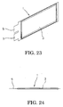
- a flat-rechargeable battery 1 formed in a plate shape as shown in Fig. 23 and Fig. 24 is used in many technical fields, and this flat-rechargeable battery 1 has a pair of electrode terminals 5, 7 in a thin piece shape projecting in one direction from a flat case 3.
- the flat-rechargeable batteries 1 also undergo a charge/discharge test for quality inspection several times after produced in a factory, and thereafter acceptable products are half-charged to be shipped as products.
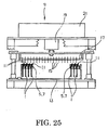
- Fig. 25 shows a charge/discharge testing device for flat-rechargeable batteries disclosed in Japanese Unexamined Patent Application Publication No. 2000-58135
- this charge/discharge testing device 9 includes a charge/discharge rack 13 provided with a group of vertically hung clip-type coupling terminals 11 coupled with electrode terminals 5, 7 of flat-rechargeable batteries 1, a contact support 17 disposed to face the group of the coupling terminals 11 and supporting a group of contacts 15 coming into contact or separating from the coupling terminals 11, a support reciprocating mechanism 19 reciprocating the contact support 1 7 in a predetermined direction to make the corresponding coupling terminals 11 and contacts 15 come into contact with or separate from each other, and a charge/discharge power source 21 coupled with the group of the contacts 15, and the charge/discharge testing device 9 is capable of conducting a charge/discharge test of a large number of the flat-rechargeable batteries 1 at a time.
- Japanese Unexamined Patent Application Publication No. 2004-319334 discloses a charge/discharge and inspection system for flat-rechargeable batteries which includes a battery container in which many flat-rechargeable batteries are stored and arranged in a fixed direction, with electrode terminals of the flat-rechargeable batteries being inserted in many insertion holes formed in its bottom plate, and a chuck mechanism chucking the electrode terminals projecting from the insertion holes of the battery container, wherein the chuck mechanism is moved close to the battery container by a first operation (lift) mechanism after the many flat-rechargeable batteries are stored and arranged in the battery container, and thereafter the chuck mechanism is made to chuck the electrode terminals by a second operation (lift) mechanism.
- lift first operation
- lift second operation
- the charge/discharge testing device 9 is capable of conducting the charge/discharge test of the many flat-rechargeable batteries 1 at a time, but it took a lot of trouble to couple the flat-rechargeable batteries 1 (electrode terminals 5, 7) with the group of the many clip-type coupling terminals 11.
- a charging and discharging apparatus is known according to which the skin on the surface of an electrode is removed by moving the contact point of the contact part pressed on the surface of the electrode when the contact part of the contact means is brought into contact with the electrode of the battery to preform a charging and discharging test.
- the electrodes project upward from a guide aperture of a battery guide when inserting a palette which stores a number of batteries into the inside of a device body.
- a contact part of the apparatus is pressed on the electrodes of the battery it swings with an inclined part by making a bend part as a fulcrum.
- the skin is removed on the surface of the electrodes by moving the top of the contact part upward.
- the present application was invented in consideration of the above-described circumstances and has a proposition to provide a chuck mechanism of a charge/discharge testing device for flat-rechargeable batteries which makes it possible to lighten the aforesaid conventionally needed troublesome works, that is, the work of coupling the flat-rechargeable batteries with the group of the clip-type coupling terminals and the work of storing and arranging the many flat-rechargeable batteries in the battery container and which is capable of surely chucking the flat-rechargeable batteries (electrodes).
- a chuck mechanism is provided comprising the features of claim 1. Further embodiments are mentioned in the dependent claims.
- the chuck mechanism wherein the second guide is made up of a pair of two positioning pins fastening a positioner that is formed in the battery storage corresponding to each of the chuck units, and each pair of the positioning pins becomes shorter in order from both ends toward a center of the plurality of chuck units arranged in parallel.
- the chuck units include a roller-retaining member which is movable in a front and rear direction of a support base when a driver mounted on the support base is driven and in which a plurality of divided roller-retaining members are movably arranged in parallel via a shaft extending in a left and right direction of the support base, the divided roller-retaining members arranging in parallel a plurality of pairs of rollers vertically on each front surface of the divided roller-retaining members, and a chuck-retaining member in which a plurality of divided chuck-retaining members each making one unit with each of the divided roller-retaining members are resiliently and movably arranged in parallel via the shaft extending in the left and right direction of the support base, wherein the divided chuck-retaining members each have a plurality of chuck members each made up of a pair of two strip-formed metal plates inserted through a gap between each of the pairs of rollers, with front end sides of the metal plates fanning out in a V shape in a
- Yet another embodiment of the present application is the chuck mechanism, wherein an oxide film exfoliating/fastening member having a large number of projections on a fastening surface of the oxide film exfoliating/fastening member is fixed on front ends of a pair of two chuck members, and yet another embodiment of the present application is the chuck mechanism according to the above embodiment, wherein the oxide film exfoliating/fastening member has a guide inclining inward from the front end sides of the chuck members toward the fastening surface.
- Yet another embodiment of the present application is the chuck mechanism, wherein slits are formed in a front and rear direction in the front ends of the chuck members, and the oxide film exfoliating/fastening member is fixed on each front end of the chuck members demarcated by the slits.
- the present application is structured such that, in the battery storage side, it is only necessary to fasten the flat-rechargeable batteries which are arranged in parallel, and when the battery storage is thereafter moved close to the chuck mechanism, the first guide adjusts a chuck width of the chuck mechanism according to a battery storage width of the battery storage, and thereafter the chuck units resiliently and continuously joined with the first guide are positioned with the flat-rechargeable batteries by the second guide automatically and resiliently in sequence, which as a result has an advantage of improving chuck accuracy while reducing a work load.
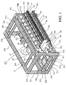
- Fig. 1 to Fig. 12 show a chuck mechanism of a charge/discharge testing device for flat-rechargeable batteries according to an embodiment of the present invention
- 31 denotes a support base which is a rectangular parallelepiped frame made up of a plurality of support posts 31 a to 31 w disposed on front, back, right, and left sides, and as shown in Fig. 1 and Fig.
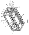
- a mounting plate 33 in a rectangular shape in a plane view is mounted between the support post 31 w, which is bridged between the left and right support posts 31o, 31 p, and the support post 31 q, which is bridged between the support posts 31 m, 31 n on left and right rear sides, and on the mounting plate 33, an air cylinder (driver) 37 whose piston rod 35 is expandable/contractible in a front and rear direction of the support base 31 is mounted as shown in Fig. 6 to Fig. 9 .
- a roller-retaining member 41 is mounted via a support frame 39, and further, a chuck-retaining member 43 facing the roller-retaining member 41 is mounted to be movable in a right and left direction of the support base 31 along one shaft 45 bridged between the left and right support posts 31k, 31l of the support base 31, and the roller-retaining member 41 and the chuck-retaining member 43 form chuck units in this embodiment.
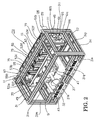
- columnar guide members 47 are inserted along the piston rod 35, one on the right side and the other one on the left side of the piston rod 35.
- a coupler plate 51 in a rectangular shape in a front view made of one plate member and having a rising wall 49 for reinforcement formed along its peripheral edge is fixed to front ends of the both guide members 47 and the piston rod 35, so as to face a front surface of the support base 31 and so as to extend long in a lateral direction.
- Six support posts 53a, 53b, 53c, 53d, 53e, 53f are fixed in an up and down direction to the coupler plate 51 at predetermined intervals, and one support post 55 and one support post 57 are fixed respectively to upper sides and lower sides of the support posts 53a, 53b, 53c, 53d, 53e, 53f so as to extend in the right and left direction of the support base 31.
- one support plate 59 and one support plate 61 both in a C shape in a side view are fixed between left end portions of the upper and lower support posts 55, 57 and between right end portions thereof respectively, and the support posts 55, 57 are coupled with upper sides of base portions 59a, 61 a of the support plates 59, 61 and with lower sides thereof respectively to form the support frame 39.
- one shaft 63 is bridged on front end sides of upper arms 59b, 61 b projecting forward from upper portions of the base portions 59a, 61 a of the support plates 59, 61, and one shaft 65 is bridged in parallel to the shaft 63 between front end sides of lower arms 59c, 61 c projecting forward from lower portions of the base portions 59a, 61 a.
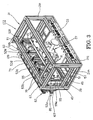
- the roller-retaining member 41 in which a plurality of divided roller-retaining members 67 are arranged in parallel is formed.
- Fig. 11 and Fig. 12 show the divided roller-retaining member 67 and a divided chuck-retaining member 69 making a unit with the divided roller-retaining member 67.
- the plural divided roller-retaining members 67 are arranged in parallel between the shafts 63, 65 to form the roller-retaining member 41 as previously described, and the plural divided chuck-retaining members 69 are arranged in parallel along the shaft 45 to form the chuck-retaining member 43.
- 71 denotes a roller mounting plate being one plate, which has, on its upper and lower portions, mounting flanges 73, 75 each having a substantially L-shaped cross section and has, on its left and right sides, rising walls 77 for reinforcement.
- retaining members 79 in a block shape through which the shaft 63 is inserted are fixed to the upper mounting flanges 73
- retaining members 81 in a block shape through which the shaft 65 is inserted are fixed to the lower mounting flanges 75, and all the divided roller-retaining members 67 are movably mounted between the upper and lower shafts 63, 65 via the retaining members 79. 81.
- the roller mounting plate 71 has, in upper and lower portions of its front surface, insertion holes 87, 89 in a rectangular shape in a front view through which later-described plurality of pairs of chuck members 83, 85 are inserted, and a long hole 91 is opened in a lateral direction between the both insertion holes 87, 89.
- a pair of roller mounting brackets 93, 95 are fixed to upper and lower sides of the upper insertion hole 87, and four pairs of columnar rollers 97 are rotatably mounted between the both roller mounting brackets 93, 95.
- the upper roller mounting bracket 93 includes: a first roller mounting bracket 93a with a substantially L-shaped cross section in whose front ends a plurality of roller insertion holes 99 having the rollers 97 inserted therethrough are opened at equal intervals; and a second roller mounting bracket 93b with a substantially L-shaped cross section disposed above the first roller mounting bracket 93a, with a small gap therebetween, and support holes 103 supporting shafts 101 of the rollers 97 are provided in a front end portion of the second roller mounting bracket 93b in correspondence to the roller insertion holes 99.
- support holes 105 supporting the shafts of the rollers 97 are formed in correspondence to the support holes 103, and the four pairs of rollers 97 are rotatably mounted between the roller mounting brackets 93, 95 via the roller insertion holes 99 and the support holes 103, 105.
- a similar roller mounting bracket 93 is mounted upside down on a lower side of the lower insertion hole 89, and a similar roller mounting bracket 95 is mounted upside down on an upper side of the insertion hole 89, and a four pairs of rollers 97 are rotatably mounted between the both roller mounting brackets 93, 95.
- the divided roller-retaining member 67 is thus structured, and the plural divided roller-retaining members 67 are movably mounted between the shafts 63, 65 to form the roller-retaining member 41 movable in the front and rear direction of the support base 31 by the air cylinder 37 being driven.
- support brackets 107, 109 are mounted at substantially centers of the left and right support posts 31 k, 31l of the support base 31 respectively, and the single shaft 45 is bridged between the both support brackets 107, 109 in parallel to the shafts 63, 65.
- the shaft 45 is inserted through retaining members 111 of the divided chuck-retaining members 69.
- the divided chuck-retaining member 69 and the divided roller-retaining member 67 are formed as a unit to make a pair, and the plural divided chuck-retaining members 69 are arranged in parallel along the shaft 45 to form the chuck-retaining member 43.
- 113 denotes a thick chuck mounting plate disposed along the roller mounting plate 71, and at a center of its rear surface side, the retaining member 111 in the block shape through which the shaft 45 is inserted is mounted.
- the four chuck members 83 disposed in parallel in the lateral direction and the four chuck members 85 disposed in parallel in the lateral direction, each corresponding to the aforesaid each pair of the rollers 97, are disposed in two tiers.
- the chuck members 83, 85 are each made up of a pair of two metal plates 115, 117 in a strip shape having a spring property and made of, for example, phosphor bronze or the like, and rear end sides of the two metal plates 115, 117 are overlaid one on the other to be inserted through a through hole (not shown) formed in the chuck mounting plate 113.
- the rear ends of the metal plates 115 projecting from a rear surface of the chuck mounting plate 113 are bent in an L shape along the rear surface of the chuck mounting plate 113 to be screw-fixed to the rear surface.
- the rear ends of the other metal plates 117 projecting from the rear surface of the chuck mounting plate 113 are bent in an L shape along the rear surface of the chuck mounting plate 113 to be screw-fixed to the rear surface, and as shown in Fig. 12 , the rear ends of the metal plates 115, 117 are cut out to a short length in the up and down direction to be disposed on the upper and lower side of the rear surface of the chuck mounting plate 113.
- Electric wires from the charge/discharge testing device can be coupled with the rear ends of the metal plates 11 5, 11 7 projecting from the rear surface of the chuck mounting plate 113.
- the aforesaid pairs of rollers 97 are each disposed so as to correspond to each of the chuck members 83, 85 (metal plates 115, 117) projecting to a front side of the chuck mounting plate 113, and each pair of the metal plates 115, 117 is inserted between each pair of the rollers 97.
- each pair of the metal plates 115, 117 (chuck member 83, 85) fanning out in a substantially V shape in a plane view is closed by each pair of the rollers 97.
- slits 119 are formed in the front and rear direction in the front ends of the metal plates 115, 117, three slits 119 being formed in each of the metal plates 115, 117 forming the upper chuck member 83 and two slits 119 being formed in each of the metal plates 115, 117 forming the lower chuck member 85.
- a pair of oxide film exfoliating/fastening members (hereinafter, referred to as "exfoliating/fastening members) 121 are caulk-fixed to tip sides demarcated by the slits 119 in each pair of the metal plates 115, 117.
- mounting holes 123 to which the exfoliating/fastening members 121 are caulk-fixed are provided in the front end sides demarcated by the slits 119 in the metal plates 115, 117.
- the exfoliating/fastening members 121 each have a leg portion 121 a caulk-fixed to the mounting hole 123 and a head portion 121 b in a thick disk shape in a plane view integrally formed with the leg portion 121 a.
- Six spike pins 127 are projectingly provided on a fastening surface 125 being a top portion of the head portion 121b, and as will be described later, when the metal plates 115, 117 are closed by the pair of rollers 97 while an electrode terminal 5, 7 of the flat-rechargeable battery 1 is interposed between the metal plates 115, 117, the six spike pins 127 of each of the exfoliating/fastening members 121 on one side and the six spike pins 127 of each of the exfoliating/fastening member 121 on the other side come into pressure contact with front and rear surfaces of the electrode terminal 5, 7 respectively to exfoliate the oxide films formed on the surfaces of the electrode terminal 5, 7.
- guides 129 inclining inward from the front end sides of the chuck members 83, 85 toward the fastening surfaces 125 are formed on the head portions 121b, and the guide members 129 guide the displaced electrode terminals 5, 7 to the fastening surfaces 125.
- the plural divided chuck-retaining members 69 are arranged in parallel along the shaft 45 to form the chuck-retaining member 43, and as shown in Fig. 1 , Fig. 6 , and Fig. 10 , on the support post 31l side of the support base 31, one width-deciding/fastening member (first guide) 135 fastening a battery pressing plate 133 of a later-described magazine (battery storage) 131 is movably mounted on the shaft 45.
- the width-deciding/fastening member 135 includes: a base 137 in a rectangular shape in a plane view that is equal in thickness to the chuck mounting plate 113; and a fastening arm 139 in a U-shape in a plane view mounted on a front surface of the base 137, and the retaining member 111 is mounted on a rear surface side of the base 137.
- bottomed shaft insertion holes 141 each having a step therein are provided, and as shown in Fig. 10 , positioning shafts 143 are inserted in the both shaft insertion holes 141 one per each, and further, a coil spring 145 is wound around an outer periphery of each of the positioning shafts 143.
- the positioning shaft 143 inserted in the shaft insertion hole 141 on the support post 311 side is inserted and supported in a spring insertion hole (not shown) of a support bracket 109 mounted on the support post 311, and one end side of the coil spring 145 is inserted and retained in the spring insertion hole.
- the not-shown positioning shaft inserted in the shaft insertion hole (not shown) opposite the support post 31l and its coil spring are inserted and supported in a spring insertion hole 147 provided in the chuck mounting plate 113 adjacent thereto.
- a spring mounting hole 149 in which one end side of the coil spring 145 is inserted and retained is formed in a left side surface of the chuck mounting plate 113, and thereunder, a positioning pin (rotation stopping pin) 151 is projectingly provided.
- a spring insertion hole 147 in which the coil spring 145 on the adjacent chuck mounting plate 113 side is insertable and a positioning pin insertion hole 1 53 in which the positioning pin 1 51 is insertable are formed.
- receiving parts 1 55, 1 57 retaining the coil spring 145 and the positioning pin 151 of the chuck mounting plate 113 adjacent to the support post 31 k are formed, so that the divided chuck-retaining members 69 and the width positioning/fastening member 135 which are arranged along the shaft 45 between the left and right support posts 31 k, 31l are continuously provided via the coil springs 145 and the positioning pins 151, and are arranged at equal intervals between the supports 31 k, 31l owing to spring forces of the coil springs 145.
- Fig. 14 shows the magazine 131 in which a large number of the flat-rechargeable batteries 1 as targets of the charge/discharge test are stored, and as shown in the drawing, the magazine 131 includes: a pair of side plates 161, 163 disposed on the left and right of a base 1 59 in a rectangular shape in a plane view; a plurality of partition walls 165 arranged between the both side plates 161, 163; the battery pressing plate 133 disposed on one end side (plate 163 side) of a group of the partition walls 165 so as to face the width positioning/fastening member 135; and four guide stays 167 passing through four corners of each of the partition walls 165 and the battery pressing plate 133 and bridged between four corners of the side plate 161 and four corners of the side plate 163, and the partition walls 165 and the battery pressing plate 133 are movable along the guide stays 167.
- the partition walls 165 demarcate and form storage chambers each storing one flat-rechargeable battery 1 in a vertical direction, with the electrode terminals 5, 7 projected forward (chuck members 83, 85 side).
- the number of the storage chambers demarcated by the partition walls 165 is equal to the number of the upper and lower chuck members 83, 85.
- a not-shown screwing part is formed, and one end side of one adjustment screw 169 inserted through the side plate 163 is screwed to the screwing part.
- the adjustment screw 169 is loosened, the partition walls 165 become movable along the guide stays 167 between the side plate 161 and the battery pressing plate 133, and when the adjustment screw 169 is fastened after the flat-rechargeable batteries 1 are stored in the storage chambers, one for each, the battery pressing plate 133 presses and fixes the partition walls 165, so that a battery storage width L of the magazine 131 is decided according to the number of the partition walls 165.
- a tapered fastened piece (positioner) 1 71 projecting toward the fastening arm 139 is provided, and as will be described later, when the magazine 1 31 is pulled toward the chuck mechanism 173 of this embodiment, the fastening arm 139 first fastens the fastened piece 171 as shown in Fig. 19 .
- the positions of the divided chuck-retaining members 69 and the width-deciding/fastening member 135 which are arranged along the shaft 45 between the left and right support posts 31 k, 31l at equal intervals owing to the spring forces of the coil springs 145 as previously described are newly adjusted so that they are arranged at equal intervals within a dimension of the battery storage width L owing to the spring forces.
- the positioning pins 1 51 provided on the respective divided chuck-retaining members 69 are inserted in the pin insertion holes 153 of the adjacent divided chuck-retaining members 69 to position the divided chuck-retaining members 69, which prevent the rotation of the chuck-retaining members 43 around the shaft 45.
- second fastened pieces (positioners) 1 75 projecting toward the chuck mechanism 173 are provided, and the fastened pieces 175 are tapered and are located on a more back side than the fastened piece 1 71.
- two positioning pins (second guides) 177 inserted through the long hole 91 of the roller mounting plate 71 are provided so as to project forward, and when the fastening arm 1 39 fastens the fastened piece 171 as is previously described and the magazine 131 is thereafter further pulled toward the chuck mechanism 173, the two positioning pins 177 fasten the single fastened piece 1 75 facing them, from left and right.
- pairs of the two positioning pins 1 77 are formed to become shorter in order from those of the left and right divided chuck-retaining members 69 to those of the center divided chuck-retaining member 69, so that all the positioning pins 177 do not fasten the fastened pieces 1 75 at a time but the positioning pins 177 sequentially fasten the fastened pieces 175 in order from the left and right side positioning pins 177 to the center positioning pins 177.
- the chuck mechanism 1 73 according to this embodiment and the magazine 131 are structured as above, and to conduct the charge/discharge test of the flat-rechargeable batteries 1 by using the chuck mechanism 173, the chuck mechanism 173 is first placed on a predetermined mounting table 1 79 as shown in Fig. 16 .
- a guide mechanism 185 including two guide rails 181 and a movable table 183 movably mounted on the two guide rails 181 is installed.
- a piston rod of a not-shown air cylinder mounted on a rear surface side of the mounting table 179 is coupled with the movable table 183, so that the mounting table 179 is movable in the front and rear direction along the guide rails 181 when the air cylinder is driven.
- the magazine 131 in Fig. 14 in whose storage chambers the plural flat-rechargeable batteries 1 are stored is carried onto the movable table 183 by a stacker crane and the base 1 59 is fixed to the movable table 183.
- the adjustment screw 169 has already been fastened and the predetermined battery storage width L has been set.
- the magazine 131 is disposed on the movable table 183 so as to face the chuck mechanism 1 73, and the electrode terminals 5, 7 of the flat-rechargeable batteries 1 are disposed to face the chuck members 83, 85 respectively.
- the chuck mechanism 1 73 and the magazine 131 are pre-designed so that at this time, the fastening arm 139 of the width-deciding/fastening member 135 faces the battery pressing plate 133. Further, the number of the storage chambers demarcated by the partition walls 165 is equal to the number of the chuck members 83, 85 as previously described, and therefore, the number of the chuck members 83, 85 and the number of the flat-rechargeable batteries 1 are equal to each other.
- the fastening arm 139 first fastens the fastened piece 171 of the battery pressing plate 133 while the magazine 131 moves along the guide rails 181 toward the chuck mechanism 173.
- the adjustment is automatically made anew so that the divided chuck-retaining members 69 arranged between the left and right support posts 31 k, 31l at equal intervals owing to the spring forces of the coil springs 145 are arranged at equal intervals between the width fastening member 135 and the support 31 k within the dimension of the battery storage width L owing to the spring forces, and at this time, the positioning pins 151 are inserted in the pin insertion holes 153 of the adjacent divided chuck-retaining members 69 to position the divided chuck-retaining members 69, so that the rotation of the chuck-retaining member 43 around the shaft 45 is constantly prevented.
- the divided chuck-retaining members 69 therebetween are arranged at equal intervals owing to the spring forces of the coil springs 145, and then their intervals are further equally adjusted sequentially. Then, as shown in Fig. 19 and Fig. 20 , when the magazine 131 moves by a predetermined distance and the air cylinder stops, the electrode terminals 5, 7 of each of the flat-rechargeable batteries 1 are disposed between the two metal plates 115, 117 of the upper chuck member 83 and the two metal plates 115, 117 of the lower chuck members 85 respectively.
- the plural slits 119 are provided in the front and rear direction in the front end of each of the metal plates 115, 117 to divide the front end sides of the metal plates 115, 117 to small parts, and therefore, even with an assembly error or the like in the metal plates 115, 117, the exfoliating/fastening members 121 of the metal plates 115, 117 surely come into pressure-contact with the surfaces of the electrode terminals 5, 7, so that the spike pins 127 projecting from the fastening surfaces 125 exfoliate the oxide films formed on the surfaces of the electrode terminals 5, 7.
- the fastening arm 139 first fastens the fastened piece 171 of the battery pressing plate 133, so that the chuck width is adjusted, and thereafter, while the positioning pins 1 77 with the longer length projectingly provided on the left and right divided chuck-retaining members 69 first fasten the fastened pieces 175, the divided chuck-retaining members 69 therebetween are arranged evenly by the spring forces of the coil springs 145 so that their intervals are equally adjusted in sequence, and as a result, chuck accuracy is improved while a work load is lightened.
- the fanning-out metal plates 115, 117 of the chuck members 83, 85 are closed at a time by using the pairs of rollers 97, which enables a smooth opening/closing operation of the metal plates 115, 117.
- the plural slits 119 are provided in the front and rear direction in the front ends of the metal plates 115, 117 to divide the front end sides of the metal plates 115, 117 into small parts and the displaced electrode terminals 5, 7 are guided to the fastening surfaces 125 by the guide members 129 of the exfoliating/fastening members 121.
- This structure has advantages that, even if the metal plates 115, 117 have assembly errors or the like, the electrode terminals 5, 7 can be surely fastened by the metal plates 115, 117 (exfoliating/fastening members 121) and the oxide films on the surfaces of the electrode terminals 5, 7 can be exfoliated favorably by the spike pins 127.
- the plural divided roller-retaining members 67 are arranged in parallel in the lateral direction to form the roller-retaining member 41 and the plural divided chuck-retaining members 69 are arranged in parallel in the lateral direction to form the chuck-retaining member 43, which has an advantage of facilitating the change of individual components and maintenance.
- the pairs of two positioning pins 177 being the second guides are formed to become shorter in order from those of the left and right divided chuck-retaining members 69 toward those of the center divided chuck-retaining member 69, but the pairs of two positioning pins 177 may be formed to become shorter in order from those on the side of the width-deciding/fastening member 135 being the first guide toward those on the other support 31 k side, and such an embodiment is capable of attaining the desired proposition similarly to the above-described embodiment.
- the driver moving the roller-retaining member 41 back and forth, the air cylinder 37 is used, but the driver is not limited to the air cylinder, and a motor of any other actuator may be used as the driver.
Landscapes
- Chemical & Material Sciences (AREA)
- Chemical Kinetics & Catalysis (AREA)
- Electrochemistry (AREA)
- General Chemical & Material Sciences (AREA)
- Engineering & Computer Science (AREA)
- Manufacturing & Machinery (AREA)
- Battery Mounting, Suspending (AREA)
- Secondary Cells (AREA)
Claims (6)
- Spannmechanismus einer Lade- / Entlade-Testvorrichtung für flache, wiederaufladbare Batterien (1), gekennzeichnet durch eine erste Führung (135, 139), die auf einer Welle (45) beweglich gelagert ist und mit einem Batteriespeicher (131) koppelbar ist, der mehrere flache wiederaufladbare Batterien enthält, die parallel angeordnet sind, wobei mehrere Spannrückhaltekörper (49) längs der Welle (45) in gleichen und einstellbaren Intervallen parallel angeordnet sind, wobei jeder der Spannrückhaltekörper (69) mehrere Spannkörper (83, 85) aufweist und jeder Spannkörper eine zweite Führung (177) hat, die dazu dient, jede der Spanneinheiten mit einer vorbestimmten Anzahl entsprechender flacher, wiederaufladbarer Batterien in dem Batteriespeicher federnd zu positionieren und wobei die erste Führung mit einem Befestigungsarm (139) versehen ist, der mit einem Stück (171) auf dem Batteriespeicher in Eingriff ist oder verbindbar ist, um die Spannrückhaltekörper (69) in einer Abmessung der Batteriespeicherbreite anzuordnen.
- Spannmechanismus der Lade- / Entlade-Testvorrichtung für flache, wiederaufladbare Batterien nach Anspruch 1, dadurch gekennzeichnet, daß die zweite Führung (177) aus einem Paar zweier Positionierungsstifte aufgebaut ist, die das Stück (171) festhalten, das in dem Batteriespeicher (131) entsprechend mit jedem der Spannkörper (83, 85) gebildet wird, und daß jedes Paar Positionierungsstifte von beiden Enden in Richtung auf eine Mitte der mehreren parallel angeordneten Spannkörper (83, 85) kürzer wird.
- Spannmechanismus der Lade- / Entlade-Testvorrichtung für flache, wiederaufladbare Batterien gemäß Anspruch 1 oder 2, dadurch gekennzeichnet, daß die Spannkörper (83, 85) einen Rollenrückhaltekörper (41) aufweisen, der in Vorwärts- und Rückwärtsrichtung einer Tragbasis (31) beweglich ist, sobald ein Antriebselement, das auf der Tragbasis (31) angebracht ist, angetrieben wird, und bei dem mehrere geteilte Rollenrückhaltekörper (67) durch eine Welle (63), die sich in einer linken und rechten Richtung der Tragbasis (31) erstreckt, parallel angeordnet sind, wobei die unterteilten Rollenrückhaltekörper (67) in mehreren Paaren aus Rollen (97) parallel liegen und diese Rollen senkrecht auf jeder vorderen Oberfläche der unterteilen Rollenrückhaltekörper (67) angeordnet sind; und daß ein Spannrückhaltekörper (43), bei dem mehrere unterteilte Spannrückhaltekörper (69), von denen jeder mit den unterteilten Rollenrückhaltekörpern (67) eine Einheit bildet, federnd und beweglich parallel durch die Welle (45) angeordnet sind, sich in Richtung nach links und nach rechts der Tragbasis (31) erstrecken; und ferner gekennzeichnet durch mehrere Spannkörper (83, 85), von denen jeder aus einem Paar streifenförmiger Metallplatten besteht, die durch einen Spalt zwischen jedem der Rollenpaare eingesteckt sind, mit vorderen Stirnseiten der Metallplatten (115, 117) in Draufsicht in einer V-Form ausfächern und mit den hinteren Stirnseiten der Metallplatten mit elektrischen Drähten der Lade- / Entlade-Testvorrichtung gekoppelt sind.
- Spannmechanismus der Lade- / Entlade-Testvorrichtung für flache, wiederaufladbare Batterien nach Anspruch 3, dadurch gekennzeichnet, daß auf den vorderen Enden eines Paares aus zwei Spannkörpern (83, 85) ein Oxidfilm / Peeling / Befestigungskörper (121) befestigt ist, der eine große Zahl von Vorsprüngen auf einer Befestigungsoberfläche (125) des Oxidfilm / Peeling / Befestigungskörpers aufweist.
- Spannmechanismus der Lade- / Entlade-Testvorrichtung für flache, wiederaufladbare Batterien nach Anspruch 4, dadurch gekennzeichnet, daß der Oxidfilm / Peeling / Befestigungskörper (121) eine Führung (129) aufweist, welche von den vorderen Stirnseiten der Spannkörper (83, 85) in Richtung auf die Befestigungsoberfläche (125) nach innen geneigt ist.
- Spannmechanismus der Lade- / Entlade-Testvorrichtung für flache, wiederaufladbare Batterien nach Anspruch 4 oder Anspruch 5, dadurch gekennzeichnet, daß in den vorderen Enden der Spannkörper (83, 85) in einer Richtung nach vorne oder einer Richtung nach hinten Schlitze (119) ausgebildet sind, und daß der Oxidfilm / Peeling / Befestigungskörper (121) auf jedem vorderen Ende der Spannkörper, abgegrenzt durch die Schlitze (119), befestigt ist.
Applications Claiming Priority (1)
| Application Number | Priority Date | Filing Date | Title |
|---|---|---|---|
| JP2010138189A JP5498273B2 (ja) | 2010-06-17 | 2010-06-17 | 薄型二次電池用充放電試験装置のチャック機構 |
Publications (3)
| Publication Number | Publication Date |
|---|---|
| EP2398089A2 EP2398089A2 (de) | 2011-12-21 |
| EP2398089A3 EP2398089A3 (de) | 2013-04-17 |
| EP2398089B1 true EP2398089B1 (de) | 2016-10-05 |
Family
ID=44503466
Family Applications (1)
| Application Number | Title | Priority Date | Filing Date |
|---|---|---|---|
| EP11004944.2A Active EP2398089B1 (de) | 2010-06-17 | 2011-06-16 | Futtermechanismus einer Lade-/Entladeprüfvorrichtung für flache wiederaufladbare Batterien |
Country Status (4)
| Country | Link |
|---|---|
| US (1) | US8618804B2 (de) |
| EP (1) | EP2398089B1 (de) |
| JP (1) | JP5498273B2 (de) |
| CN (1) | CN102290615B (de) |
Cited By (1)
| Publication number | Priority date | Publication date | Assignee | Title |
|---|---|---|---|---|
| DE102017203957A1 (de) | 2017-03-10 | 2018-09-13 | Thyssenkrupp Ag | Formationsanlage und Verfahren zum Zustellen in eine Formationsanlage |
Families Citing this family (27)
| Publication number | Priority date | Publication date | Assignee | Title |
|---|---|---|---|---|
| JP5834359B2 (ja) * | 2012-02-28 | 2015-12-16 | 株式会社ダイフク | 物品収納設備 |
| JP5804975B2 (ja) * | 2012-02-28 | 2015-11-04 | 富士通テレコムネットワークス株式会社 | 二次電池の充放電装置 |
| JP5870405B2 (ja) * | 2012-02-28 | 2016-03-01 | 株式会社ダイフク | 物品搬送設備 |
| JP5838520B2 (ja) * | 2012-02-28 | 2016-01-06 | 株式会社ダイフク | 物品搬送設備 |
| CN102790299B (zh) * | 2012-07-27 | 2014-10-15 | 东华大学 | 一种适合锂电池化成自动化生产线的平板式电极夹具 |
| JP2014102883A (ja) * | 2012-11-16 | 2014-06-05 | Fujitsu Telecom Networks Ltd | チャック装置 |
| EP2993725B1 (de) * | 2013-05-01 | 2018-11-21 | Nissan Motor Co., Ltd | Lade- und entladeprüfvorrichtung und lade- und entladeprüfverfahren für dünne sekundärbatterie |
| KR101509206B1 (ko) | 2013-07-23 | 2015-04-10 | (주)이티에이치 | 그립퍼의 교체가 용이한 전지 충방전용 지그 |
| US9520727B2 (en) | 2013-08-29 | 2016-12-13 | Lg Chem, Ltd. | Gripper assembly for battery charging and discharging |
| JP6233105B2 (ja) * | 2014-03-07 | 2017-11-22 | 株式会社富士通テレコムネットワークス福島 | 通電チャッキング耐久試験装置 |
| JP6323131B2 (ja) * | 2014-04-09 | 2018-05-16 | 日産自動車株式会社 | フィルム外装電池の加圧装置 |
| JP6292023B2 (ja) * | 2014-05-20 | 2018-03-14 | 日産自動車株式会社 | 多角形部材の整列装置 |
| KR101937995B1 (ko) * | 2015-06-04 | 2019-01-11 | 주식회사 엘지화학 | 전지팩 기능 검사장치 |
| JP6540368B2 (ja) * | 2015-08-21 | 2019-07-10 | 日産自動車株式会社 | 電池セル収納装置 |
| CN105449287B (zh) * | 2015-10-23 | 2018-02-13 | 万向一二三股份公司 | 一种锂电池化成工装 |
| JP6759571B2 (ja) * | 2015-12-15 | 2020-09-23 | 株式会社豊田自動織機 | 電池パック |
| CN105826486B (zh) * | 2016-04-29 | 2018-08-17 | 无锡港盛重型装备有限公司 | 一种蓄电池的保护装置 |
| TWI629816B (zh) * | 2017-07-21 | 2018-07-11 | 廣運機械工程股份有限公司 | 二次電池充放電卡匣 |
| CN109301305B (zh) * | 2018-10-29 | 2020-04-24 | 惠安佳瑞汽车销售服务有限公司 | 一种用于新能源汽车电池组装的装载设备 |
| CN111208321B (zh) * | 2018-11-02 | 2021-11-23 | 沈阳新松机器人自动化股份有限公司 | 一种兼容型软包电池加电测试装置 |
| CN111755760B (zh) * | 2019-03-28 | 2021-08-24 | 浙江吉智新能源汽车科技有限公司 | 一种电池包验证装置 |
| JP7159965B2 (ja) | 2019-04-22 | 2022-10-25 | トヨタ自動車株式会社 | 二次電池モジュール及び二次電池モジュールの製造方法 |
| CN115917833A (zh) * | 2020-08-28 | 2023-04-04 | 平田机工株式会社 | 试验方法和制造方法 |
| TWI780522B (zh) * | 2020-11-25 | 2022-10-11 | 致茂電子股份有限公司 | 間距可變之電池夾具及具備該夾具之電池化成設備 |
| KR102383403B1 (ko) * | 2021-09-17 | 2022-04-25 | 주식회사 원익피앤이 | 배터리 충방전 테스트 지그 |
| CN115951243B (zh) * | 2022-12-23 | 2023-08-22 | 广州市虎头电池集团股份有限公司 | 一种碱性电池批量测试装置 |
| EP4621894A1 (de) * | 2024-03-20 | 2025-09-24 | MacroCaps ApS | Energiespeicheranordnung für energiespeichervorrichtungen |
Family Cites Families (13)
| Publication number | Priority date | Publication date | Assignee | Title |
|---|---|---|---|---|
| DE3207545C1 (de) * | 1982-03-03 | 1983-08-25 | Deta-Akkumulatorenwerk Gmbh, 3422 Bad Lauterberg | Prüfgerät für die Prüfung eines Akkumulators |
| JPH11271409A (ja) * | 1998-03-23 | 1999-10-08 | Sony Corp | 電池トレイ及び電池の試験方法 |
| JP2000058135A (ja) | 1998-08-10 | 2000-02-25 | Toshiba Battery Co Ltd | 薄型二次電池用充放電装置 |
| KR100326898B1 (ko) * | 2000-07-12 | 2002-03-06 | 신동희 | 리튬폴리머 전지의 충,방전장치 |
| JP2002134176A (ja) * | 2000-10-30 | 2002-05-10 | Mikuni Kogyo:Kk | リチウムポリマー電池の充放電・検査機構 |
| JP2002298929A (ja) * | 2001-03-30 | 2002-10-11 | Japan System Engineering Kk | ポリマーラミネート型二次電池の検査装置 |
| JP2003151644A (ja) * | 2001-11-13 | 2003-05-23 | Nyuurii Kk | バッテリーの充放電試験方法及びその装置 |
| JP2004319334A (ja) | 2003-04-17 | 2004-11-11 | Nittetsu Elex Co Ltd | 扁平型電池の充放電及び検査システム |
| US7193524B2 (en) * | 2003-04-29 | 2007-03-20 | Fisher Research Labs, Inc. | Systems and methods for a portable walk-through metal detector |
| CA2539723A1 (en) * | 2003-09-22 | 2005-04-07 | Valence Technology, Inc. | Electrical systems, power supply apparatuses, and power supply operations methods |
| JP2005197179A (ja) * | 2004-01-09 | 2005-07-21 | Toyota Motor Corp | 単電池および組電池 |
| US7916452B2 (en) * | 2004-11-25 | 2011-03-29 | Panasonic Corporation | Method of producing a coin-type electrochemical element |
| US8026698B2 (en) * | 2006-02-09 | 2011-09-27 | Scheucher Karl F | Scalable intelligent power supply system and method |
-
2010
- 2010-06-17 JP JP2010138189A patent/JP5498273B2/ja active Active
-
2011
- 2011-06-16 US US13/161,928 patent/US8618804B2/en active Active
- 2011-06-16 EP EP11004944.2A patent/EP2398089B1/de active Active
- 2011-06-17 CN CN201110163955.5A patent/CN102290615B/zh active Active
Cited By (1)
| Publication number | Priority date | Publication date | Assignee | Title |
|---|---|---|---|---|
| DE102017203957A1 (de) | 2017-03-10 | 2018-09-13 | Thyssenkrupp Ag | Formationsanlage und Verfahren zum Zustellen in eine Formationsanlage |
Also Published As
| Publication number | Publication date |
|---|---|
| JP5498273B2 (ja) | 2014-05-21 |
| US8618804B2 (en) | 2013-12-31 |
| JP2012003959A (ja) | 2012-01-05 |
| CN102290615A (zh) | 2011-12-21 |
| US20110309837A1 (en) | 2011-12-22 |
| CN102290615B (zh) | 2015-09-09 |
| EP2398089A2 (de) | 2011-12-21 |
| EP2398089A3 (de) | 2013-04-17 |
Similar Documents
| Publication | Publication Date | Title |
|---|---|---|
| EP2398089B1 (de) | Futtermechanismus einer Lade-/Entladeprüfvorrichtung für flache wiederaufladbare Batterien | |
| KR101361411B1 (ko) | 박형 이차 전지용 충방전 시험 장치의 척 기구 | |
| EP3127662A1 (de) | Industrieroboter | |
| CN205734017U (zh) | 一种加工手机金属后盖卡扣的cnc治具 | |
| CN113363647A (zh) | 电池装置以及具有电池装置的机动车 | |
| CN112928397B (zh) | 电池模块、包括电池模块的电池组和包括电池组的车辆 | |
| CN219084310U (zh) | 用于气密性检测的施压装置及气密性检测设备 | |
| JP2003059543A (ja) | 充放電装置 | |
| US11502325B2 (en) | Battery stack assemblies and methods for replacing a battery cell | |
| JP2010205442A (ja) | 電池モジュール保持部材、組電池、組電池の製造方法 | |
| CN109570951B (zh) | 一种自动上料机 | |
| CN101155491A (zh) | 分隔件安装机构、部件安装夹具、具有分隔件的部件的制造方法 | |
| CN217992722U (zh) | 电芯拆解机构及电池拆解系统 | |
| CN118117192A (zh) | 一种横端子适用不同厚度电池及膨胀收缩自动调节装置 | |
| CN112103430B (zh) | 一种软包电池定间距拘束托盘 | |
| JP7443477B1 (ja) | 充放電検査装置および充放電検査方法 | |
| CN220921369U (zh) | 电池模组焊接工装及其压板、焊接设备及电池生产系统 | |
| CN209987395U (zh) | 手机电池压盖装置 | |
| CN219620287U (zh) | 一种电芯上料结构 | |
| CN223029483U (zh) | 一种电芯定位装置 | |
| EP4593135A2 (de) | Schale und sekundärbatterieherstellungsvorrichtung | |
| CN218800094U (zh) | 一种承载装置 | |
| CN219106230U (zh) | 一种电芯二次折极耳机构 | |
| CN107525989A (zh) | 电池管理单元插拔测试装置 | |
| US7830670B2 (en) | Sliding card carrier |
Legal Events
| Date | Code | Title | Description |
|---|---|---|---|
| AK | Designated contracting states |
Kind code of ref document: A2 Designated state(s): AL AT BE BG CH CY CZ DE DK EE ES FI FR GB GR HR HU IE IS IT LI LT LU LV MC MK MT NL NO PL PT RO RS SE SI SK SM TR |
|
| AX | Request for extension of the european patent |
Extension state: BA ME |
|
| PUAI | Public reference made under article 153(3) epc to a published international application that has entered the european phase |
Free format text: ORIGINAL CODE: 0009012 |
|
| PUAL | Search report despatched |
Free format text: ORIGINAL CODE: 0009013 |
|
| AK | Designated contracting states |
Kind code of ref document: A3 Designated state(s): AL AT BE BG CH CY CZ DE DK EE ES FI FR GB GR HR HU IE IS IT LI LT LU LV MC MK MT NL NO PL PT RO RS SE SI SK SM TR |
|
| AX | Request for extension of the european patent |
Extension state: BA ME |
|
| RIC1 | Information provided on ipc code assigned before grant |
Ipc: H01R 13/24 20060101ALI20130313BHEP Ipc: H01M 2/20 20060101ALN20130313BHEP Ipc: H01M 2/10 20060101AFI20130313BHEP Ipc: G01R 31/36 20060101ALI20130313BHEP Ipc: H01M 10/42 20060101ALI20130313BHEP |
|
| 17P | Request for examination filed |
Effective date: 20131016 |
|
| RBV | Designated contracting states (corrected) |
Designated state(s): AL AT BE BG CH CY CZ DE DK EE ES FI FR GB GR HR HU IE IS IT LI LT LU LV MC MK MT NL NO PL PT RO RS SE SI SK SM TR |
|
| 17Q | First examination report despatched |
Effective date: 20140220 |
|
| RAP1 | Party data changed (applicant data changed or rights of an application transferred) |
Owner name: FUJITSU TELECOM NETWORKS FUKUSHIMA LIMITED Owner name: NISSAN MOTOR CO., LTD. |
|
| RIC1 | Information provided on ipc code assigned before grant |
Ipc: H01M 2/10 20060101AFI20160408BHEP Ipc: H01M 2/20 20060101ALN20160408BHEP Ipc: H01M 10/42 20060101ALI20160408BHEP Ipc: G01R 31/36 20060101ALI20160408BHEP |
|
| GRAP | Despatch of communication of intention to grant a patent |
Free format text: ORIGINAL CODE: EPIDOSNIGR1 |
|
| RIN1 | Information on inventor provided before grant (corrected) |
Inventor name: NIWA, YOSHIKAZU Inventor name: KAWASAKI, TAKAHIRO Inventor name: OKAZAKI, TSUTOMU Inventor name: NISHIHARA, TAKASHI Inventor name: YASOOKA, TAKESHI Inventor name: HABE, HIROAKI |
|
| INTG | Intention to grant announced |
Effective date: 20160607 |
|
| RAP1 | Party data changed (applicant data changed or rights of an application transferred) |
Owner name: FUJITSU TELECOM NETWORKS FUKUSHIMA LIMITED Owner name: NISSAN MOTOR CO., LTD |
|
| GRAS | Grant fee paid |
Free format text: ORIGINAL CODE: EPIDOSNIGR3 |
|
| GRAA | (expected) grant |
Free format text: ORIGINAL CODE: 0009210 |
|
| AK | Designated contracting states |
Kind code of ref document: B1 Designated state(s): AL AT BE BG CH CY CZ DE DK EE ES FI FR GB GR HR HU IE IS IT LI LT LU LV MC MK MT NL NO PL PT RO RS SE SI SK SM TR |
|
| REG | Reference to a national code |
Ref country code: GB Ref legal event code: FG4D |
|
| REG | Reference to a national code |
Ref country code: CH Ref legal event code: EP |
|
| REG | Reference to a national code |
Ref country code: AT Ref legal event code: REF Ref document number: 835300 Country of ref document: AT Kind code of ref document: T Effective date: 20161015 |
|
| REG | Reference to a national code |
Ref country code: IE Ref legal event code: FG4D |
|
| REG | Reference to a national code |
Ref country code: DE Ref legal event code: R096 Ref document number: 602011030882 Country of ref document: DE |
|
| REG | Reference to a national code |
Ref country code: NL Ref legal event code: MP Effective date: 20161005 |
|
| REG | Reference to a national code |
Ref country code: LT Ref legal event code: MG4D |
|
| PG25 | Lapsed in a contracting state [announced via postgrant information from national office to epo] |
Ref country code: LV Free format text: LAPSE BECAUSE OF FAILURE TO SUBMIT A TRANSLATION OF THE DESCRIPTION OR TO PAY THE FEE WITHIN THE PRESCRIBED TIME-LIMIT Effective date: 20161005 |
|
| REG | Reference to a national code |
Ref country code: AT Ref legal event code: MK05 Ref document number: 835300 Country of ref document: AT Kind code of ref document: T Effective date: 20161005 |
|
| PG25 | Lapsed in a contracting state [announced via postgrant information from national office to epo] |
Ref country code: SE Free format text: LAPSE BECAUSE OF FAILURE TO SUBMIT A TRANSLATION OF THE DESCRIPTION OR TO PAY THE FEE WITHIN THE PRESCRIBED TIME-LIMIT Effective date: 20161005 Ref country code: GR Free format text: LAPSE BECAUSE OF FAILURE TO SUBMIT A TRANSLATION OF THE DESCRIPTION OR TO PAY THE FEE WITHIN THE PRESCRIBED TIME-LIMIT Effective date: 20170106 Ref country code: LT Free format text: LAPSE BECAUSE OF FAILURE TO SUBMIT A TRANSLATION OF THE DESCRIPTION OR TO PAY THE FEE WITHIN THE PRESCRIBED TIME-LIMIT Effective date: 20161005 Ref country code: NO Free format text: LAPSE BECAUSE OF FAILURE TO SUBMIT A TRANSLATION OF THE DESCRIPTION OR TO PAY THE FEE WITHIN THE PRESCRIBED TIME-LIMIT Effective date: 20170105 |
|
| PG25 | Lapsed in a contracting state [announced via postgrant information from national office to epo] |
Ref country code: BE Free format text: LAPSE BECAUSE OF FAILURE TO SUBMIT A TRANSLATION OF THE DESCRIPTION OR TO PAY THE FEE WITHIN THE PRESCRIBED TIME-LIMIT Effective date: 20161005 Ref country code: PL Free format text: LAPSE BECAUSE OF FAILURE TO SUBMIT A TRANSLATION OF THE DESCRIPTION OR TO PAY THE FEE WITHIN THE PRESCRIBED TIME-LIMIT Effective date: 20161005 Ref country code: IS Free format text: LAPSE BECAUSE OF FAILURE TO SUBMIT A TRANSLATION OF THE DESCRIPTION OR TO PAY THE FEE WITHIN THE PRESCRIBED TIME-LIMIT Effective date: 20170205 Ref country code: HR Free format text: LAPSE BECAUSE OF FAILURE TO SUBMIT A TRANSLATION OF THE DESCRIPTION OR TO PAY THE FEE WITHIN THE PRESCRIBED TIME-LIMIT Effective date: 20161005 Ref country code: RS Free format text: LAPSE BECAUSE OF FAILURE TO SUBMIT A TRANSLATION OF THE DESCRIPTION OR TO PAY THE FEE WITHIN THE PRESCRIBED TIME-LIMIT Effective date: 20161005 Ref country code: PT Free format text: LAPSE BECAUSE OF FAILURE TO SUBMIT A TRANSLATION OF THE DESCRIPTION OR TO PAY THE FEE WITHIN THE PRESCRIBED TIME-LIMIT Effective date: 20170206 Ref country code: FI Free format text: LAPSE BECAUSE OF FAILURE TO SUBMIT A TRANSLATION OF THE DESCRIPTION OR TO PAY THE FEE WITHIN THE PRESCRIBED TIME-LIMIT Effective date: 20161005 Ref country code: NL Free format text: LAPSE BECAUSE OF FAILURE TO SUBMIT A TRANSLATION OF THE DESCRIPTION OR TO PAY THE FEE WITHIN THE PRESCRIBED TIME-LIMIT Effective date: 20161005 Ref country code: ES Free format text: LAPSE BECAUSE OF FAILURE TO SUBMIT A TRANSLATION OF THE DESCRIPTION OR TO PAY THE FEE WITHIN THE PRESCRIBED TIME-LIMIT Effective date: 20161005 Ref country code: AT Free format text: LAPSE BECAUSE OF FAILURE TO SUBMIT A TRANSLATION OF THE DESCRIPTION OR TO PAY THE FEE WITHIN THE PRESCRIBED TIME-LIMIT Effective date: 20161005 |
|
| REG | Reference to a national code |
Ref country code: FR Ref legal event code: PLFP Year of fee payment: 7 |
|
| REG | Reference to a national code |
Ref country code: DE Ref legal event code: R097 Ref document number: 602011030882 Country of ref document: DE |
|
| PG25 | Lapsed in a contracting state [announced via postgrant information from national office to epo] |
Ref country code: RO Free format text: LAPSE BECAUSE OF FAILURE TO SUBMIT A TRANSLATION OF THE DESCRIPTION OR TO PAY THE FEE WITHIN THE PRESCRIBED TIME-LIMIT Effective date: 20161005 Ref country code: CZ Free format text: LAPSE BECAUSE OF FAILURE TO SUBMIT A TRANSLATION OF THE DESCRIPTION OR TO PAY THE FEE WITHIN THE PRESCRIBED TIME-LIMIT Effective date: 20161005 Ref country code: SK Free format text: LAPSE BECAUSE OF FAILURE TO SUBMIT A TRANSLATION OF THE DESCRIPTION OR TO PAY THE FEE WITHIN THE PRESCRIBED TIME-LIMIT Effective date: 20161005 Ref country code: DK Free format text: LAPSE BECAUSE OF FAILURE TO SUBMIT A TRANSLATION OF THE DESCRIPTION OR TO PAY THE FEE WITHIN THE PRESCRIBED TIME-LIMIT Effective date: 20161005 Ref country code: EE Free format text: LAPSE BECAUSE OF FAILURE TO SUBMIT A TRANSLATION OF THE DESCRIPTION OR TO PAY THE FEE WITHIN THE PRESCRIBED TIME-LIMIT Effective date: 20161005 |
|
| PLBE | No opposition filed within time limit |
Free format text: ORIGINAL CODE: 0009261 |
|
| STAA | Information on the status of an ep patent application or granted ep patent |
Free format text: STATUS: NO OPPOSITION FILED WITHIN TIME LIMIT |
|
| PG25 | Lapsed in a contracting state [announced via postgrant information from national office to epo] |
Ref country code: BG Free format text: LAPSE BECAUSE OF FAILURE TO SUBMIT A TRANSLATION OF THE DESCRIPTION OR TO PAY THE FEE WITHIN THE PRESCRIBED TIME-LIMIT Effective date: 20170105 Ref country code: SM Free format text: LAPSE BECAUSE OF FAILURE TO SUBMIT A TRANSLATION OF THE DESCRIPTION OR TO PAY THE FEE WITHIN THE PRESCRIBED TIME-LIMIT Effective date: 20161005 Ref country code: IT Free format text: LAPSE BECAUSE OF FAILURE TO SUBMIT A TRANSLATION OF THE DESCRIPTION OR TO PAY THE FEE WITHIN THE PRESCRIBED TIME-LIMIT Effective date: 20161005 |
|
| 26N | No opposition filed |
Effective date: 20170706 |
|
| PG25 | Lapsed in a contracting state [announced via postgrant information from national office to epo] |
Ref country code: SI Free format text: LAPSE BECAUSE OF FAILURE TO SUBMIT A TRANSLATION OF THE DESCRIPTION OR TO PAY THE FEE WITHIN THE PRESCRIBED TIME-LIMIT Effective date: 20161005 |
|
| PG25 | Lapsed in a contracting state [announced via postgrant information from national office to epo] |
Ref country code: MC Free format text: LAPSE BECAUSE OF FAILURE TO SUBMIT A TRANSLATION OF THE DESCRIPTION OR TO PAY THE FEE WITHIN THE PRESCRIBED TIME-LIMIT Effective date: 20161005 |
|
| REG | Reference to a national code |
Ref country code: CH Ref legal event code: PL |
|
| REG | Reference to a national code |
Ref country code: IE Ref legal event code: MM4A |
|
| PG25 | Lapsed in a contracting state [announced via postgrant information from national office to epo] |
Ref country code: CH Free format text: LAPSE BECAUSE OF NON-PAYMENT OF DUE FEES Effective date: 20170630 Ref country code: IE Free format text: LAPSE BECAUSE OF NON-PAYMENT OF DUE FEES Effective date: 20170616 Ref country code: LU Free format text: LAPSE BECAUSE OF NON-PAYMENT OF DUE FEES Effective date: 20170616 Ref country code: LI Free format text: LAPSE BECAUSE OF NON-PAYMENT OF DUE FEES Effective date: 20170630 |
|
| REG | Reference to a national code |
Ref country code: FR Ref legal event code: PLFP Year of fee payment: 8 |
|
| REG | Reference to a national code |
Ref country code: DE Ref legal event code: R081 Ref document number: 602011030882 Country of ref document: DE Owner name: ENVISION AESC JAPAN LTD., ZAMA-SHI, JP Free format text: FORMER OWNERS: FUJITSU TELECOM NETWORKS FUKUSHIMA LIMITED, ISHIKAWA, FUKUSHIMA, JP; NISSAN MOTOR CO., LTD., YOKOHAMA-SHI, KANAGAWA, JP Ref country code: DE Ref legal event code: R082 Ref document number: 602011030882 Country of ref document: DE Representative=s name: ZEITLER VOLPERT KANDLBINDER PATENTANWAELTE PAR, DE Ref country code: DE Ref legal event code: R082 Ref document number: 602011030882 Country of ref document: DE Representative=s name: ZEITLER VOLPERT KANDLBINDER PATENT- UND RECHTS, DE Ref country code: DE Ref legal event code: R081 Ref document number: 602011030882 Country of ref document: DE Owner name: NISSAN MOTOR CO., LTD., YOKOHAMA-SHI, JP Free format text: FORMER OWNERS: FUJITSU TELECOM NETWORKS FUKUSHIMA LIMITED, ISHIKAWA, FUKUSHIMA, JP; NISSAN MOTOR CO., LTD., YOKOHAMA-SHI, KANAGAWA, JP |
|
| PG25 | Lapsed in a contracting state [announced via postgrant information from national office to epo] |
Ref country code: MT Free format text: LAPSE BECAUSE OF NON-PAYMENT OF DUE FEES Effective date: 20170616 |
|
| REG | Reference to a national code |
Ref country code: FR Ref legal event code: TP Owner name: NISSAN MOTOR CO., LTD., JP Effective date: 20181105 |
|
| PG25 | Lapsed in a contracting state [announced via postgrant information from national office to epo] |
Ref country code: HU Free format text: LAPSE BECAUSE OF FAILURE TO SUBMIT A TRANSLATION OF THE DESCRIPTION OR TO PAY THE FEE WITHIN THE PRESCRIBED TIME-LIMIT; INVALID AB INITIO Effective date: 20110616 |
|
| PG25 | Lapsed in a contracting state [announced via postgrant information from national office to epo] |
Ref country code: CY Free format text: LAPSE BECAUSE OF NON-PAYMENT OF DUE FEES Effective date: 20161005 |
|
| PG25 | Lapsed in a contracting state [announced via postgrant information from national office to epo] |
Ref country code: MK Free format text: LAPSE BECAUSE OF FAILURE TO SUBMIT A TRANSLATION OF THE DESCRIPTION OR TO PAY THE FEE WITHIN THE PRESCRIBED TIME-LIMIT Effective date: 20161005 |
|
| REG | Reference to a national code |
Ref country code: DE Ref legal event code: R081 Ref document number: 602011030882 Country of ref document: DE Owner name: ENVISION AESC JAPAN LTD., ZAMA-SHI, JP Free format text: FORMER OWNER: NISSAN MOTOR CO., LTD., YOKOHAMA-SHI, KANAGAWA, JP Ref country code: DE Ref legal event code: R082 Ref document number: 602011030882 Country of ref document: DE Representative=s name: ZEITLER VOLPERT KANDLBINDER PATENT- UND RECHTS, DE Ref country code: DE Ref legal event code: R082 Ref document number: 602011030882 Country of ref document: DE Representative=s name: ZEITLER VOLPERT KANDLBINDER PATENTANWAELTE PAR, DE |
|
| PG25 | Lapsed in a contracting state [announced via postgrant information from national office to epo] |
Ref country code: TR Free format text: LAPSE BECAUSE OF FAILURE TO SUBMIT A TRANSLATION OF THE DESCRIPTION OR TO PAY THE FEE WITHIN THE PRESCRIBED TIME-LIMIT Effective date: 20161005 |
|
| REG | Reference to a national code |
Ref country code: GB Ref legal event code: 732E Free format text: REGISTERED BETWEEN 20200402 AND 20200408 |
|
| PG25 | Lapsed in a contracting state [announced via postgrant information from national office to epo] |
Ref country code: AL Free format text: LAPSE BECAUSE OF FAILURE TO SUBMIT A TRANSLATION OF THE DESCRIPTION OR TO PAY THE FEE WITHIN THE PRESCRIBED TIME-LIMIT Effective date: 20161005 |
|
| REG | Reference to a national code |
Ref country code: DE Ref legal event code: R079 Ref document number: 602011030882 Country of ref document: DE Free format text: PREVIOUS MAIN CLASS: H01M0002100000 Ipc: H01M0050200000 |
|
| P01 | Opt-out of the competence of the unified patent court (upc) registered |
Effective date: 20230428 |
|
| REG | Reference to a national code |
Ref country code: DE Ref legal event code: R082 Ref document number: 602011030882 Country of ref document: DE Representative=s name: KANDLBINDER, MARKUS, DIPL.-PHYS., DE |
|
| REG | Reference to a national code |
Ref country code: GB Ref legal event code: 732E Free format text: REGISTERED BETWEEN 20240425 AND 20240501 |
|
| PGFP | Annual fee paid to national office [announced via postgrant information from national office to epo] |
Ref country code: DE Payment date: 20250423 Year of fee payment: 15 |
|
| PGFP | Annual fee paid to national office [announced via postgrant information from national office to epo] |
Ref country code: GB Payment date: 20250501 Year of fee payment: 15 |
|
| PGFP | Annual fee paid to national office [announced via postgrant information from national office to epo] |
Ref country code: FR Payment date: 20250422 Year of fee payment: 15 |