EP2398031A1 - Druckknopfschalter - Google Patents
Druckknopfschalter Download PDFInfo
- Publication number
- EP2398031A1 EP2398031A1 EP09839999A EP09839999A EP2398031A1 EP 2398031 A1 EP2398031 A1 EP 2398031A1 EP 09839999 A EP09839999 A EP 09839999A EP 09839999 A EP09839999 A EP 09839999A EP 2398031 A1 EP2398031 A1 EP 2398031A1
- Authority
- EP
- European Patent Office
- Prior art keywords
- light
- mark
- push
- disposed
- light source
- Prior art date
- Legal status (The legal status is an assumption and is not a legal conclusion. Google has not performed a legal analysis and makes no representation as to the accuracy of the status listed.)
- Granted
Links
Images


Classifications
-
- H—ELECTRICITY
- H01—ELECTRIC ELEMENTS
- H01H—ELECTRIC SWITCHES; RELAYS; SELECTORS; EMERGENCY PROTECTIVE DEVICES
- H01H13/00—Switches having rectilinearly-movable operating part or parts adapted for pushing or pulling in one direction only, e.g. push-button switch
- H01H13/02—Details
- H01H13/12—Movable parts; Contacts mounted thereon
- H01H13/20—Driving mechanisms
- H01H13/22—Driving mechanisms acting with snap action
-
- H—ELECTRICITY
- H01—ELECTRIC ELEMENTS
- H01H—ELECTRIC SWITCHES; RELAYS; SELECTORS; EMERGENCY PROTECTIVE DEVICES
- H01H13/00—Switches having rectilinearly-movable operating part or parts adapted for pushing or pulling in one direction only, e.g. push-button switch
- H01H13/02—Details
- H01H13/023—Light-emitting indicators
-
- H—ELECTRICITY
- H01—ELECTRIC ELEMENTS
- H01H—ELECTRIC SWITCHES; RELAYS; SELECTORS; EMERGENCY PROTECTIVE DEVICES
- H01H13/00—Switches having rectilinearly-movable operating part or parts adapted for pushing or pulling in one direction only, e.g. push-button switch
- H01H13/02—Details
-
- H—ELECTRICITY
- H01—ELECTRIC ELEMENTS
- H01H—ELECTRIC SWITCHES; RELAYS; SELECTORS; EMERGENCY PROTECTIVE DEVICES
- H01H13/00—Switches having rectilinearly-movable operating part or parts adapted for pushing or pulling in one direction only, e.g. push-button switch
- H01H13/02—Details
- H01H13/26—Snap-action arrangements depending upon deformation of elastic members
- H01H13/28—Snap-action arrangements depending upon deformation of elastic members using compression or extension of coil springs
- H01H13/285—Snap-action arrangements depending upon deformation of elastic members using compression or extension of coil springs having a symmetrical configuration
-
- H—ELECTRICITY
- H01—ELECTRIC ELEMENTS
- H01H—ELECTRIC SWITCHES; RELAYS; SELECTORS; EMERGENCY PROTECTIVE DEVICES
- H01H5/00—Snap-action arrangements, i.e. in which during a single opening operation or a single closing operation energy is first stored and then released to produce or assist the contact movement
- H01H5/04—Energy stored by deformation of elastic members
- H01H5/06—Energy stored by deformation of elastic members by compression or extension of coil springs
-
- H—ELECTRICITY
- H01—ELECTRIC ELEMENTS
- H01H—ELECTRIC SWITCHES; RELAYS; SELECTORS; EMERGENCY PROTECTIVE DEVICES
- H01H13/00—Switches having rectilinearly-movable operating part or parts adapted for pushing or pulling in one direction only, e.g. push-button switch
- H01H13/02—Details
- H01H13/12—Movable parts; Contacts mounted thereon
- H01H13/14—Operating parts, e.g. push-button
-
- H—ELECTRICITY
- H01—ELECTRIC ELEMENTS
- H01H—ELECTRIC SWITCHES; RELAYS; SELECTORS; EMERGENCY PROTECTIVE DEVICES
- H01H9/00—Details of switching devices, not covered by groups H01H1/00 - H01H7/00
- H01H9/18—Distinguishing marks on switches, e.g. for indicating switch location in the dark; Adaptation of switches to receive distinguishing marks
- H01H2009/189—Distinguishing marks on switches, e.g. for indicating switch location in the dark; Adaptation of switches to receive distinguishing marks with a tactile symbol or indication, e.g. for blind people
-
- H—ELECTRICITY
- H01—ELECTRIC ELEMENTS
- H01H—ELECTRIC SWITCHES; RELAYS; SELECTORS; EMERGENCY PROTECTIVE DEVICES
- H01H2217/00—Facilitation of operation; Human engineering
- H01H2217/024—Profile on actuator
-
- H—ELECTRICITY
- H01—ELECTRIC ELEMENTS
- H01H—ELECTRIC SWITCHES; RELAYS; SELECTORS; EMERGENCY PROTECTIVE DEVICES
- H01H2219/00—Legends
- H01H2219/036—Light emitting elements
- H01H2219/044—Edge lighting of layer
-
- H—ELECTRICITY
- H01—ELECTRIC ELEMENTS
- H01H—ELECTRIC SWITCHES; RELAYS; SELECTORS; EMERGENCY PROTECTIVE DEVICES
- H01H2219/00—Legends
- H01H2219/054—Optical elements
- H01H2219/056—Diffuser; Uneven surface
-
- H—ELECTRICITY
- H01—ELECTRIC ELEMENTS
- H01H—ELECTRIC SWITCHES; RELAYS; SELECTORS; EMERGENCY PROTECTIVE DEVICES
- H01H2219/00—Legends
- H01H2219/054—Optical elements
- H01H2219/062—Light conductor
-
- H—ELECTRICITY
- H01—ELECTRIC ELEMENTS
- H01H—ELECTRIC SWITCHES; RELAYS; SELECTORS; EMERGENCY PROTECTIVE DEVICES
- H01H2237/00—Mechanism between key and laykey
- H01H2237/004—Cantilever
Definitions
- the present invention relates to a push-button switch that can be used, for example, in elevator landing button apparatuses, or car operating panels, etc.
- Push-button switches that can be used as elevator switches that perform designation of destination floors or opening and closing of doors, etc., have been proposed that use tactile switches in order to provide a clicking sensation during a pushing operation, and that include an illuminating portion for illuminating the push-button from inside to display a switch operating state (see Patent Literature 1, for example).
- Elevator switches include types that are embedded in wall surfaces and wall-mounted types that are mounted to wall surface panels that are attached to wall surfaces. In the wall-mounted types, it is desirable to configure the push-button switches so as to be as thin as possible in order to reduce operating panel projection.
- elevator switches By configuring elevator switches so as to impart a clicking sensation, switch operation can be recognized by sense of touch, enabling them to have superior usability. In such cases, tactile switches are also useful as elevator switches from the viewpoint of imparting a clicking sensation. However, because they are configured such that the clicking sensation is issued by turning a movable contact inside out that is formed so as to have a dome shape, it is necessary to use a large movable contact in order to increase durability and extend service life, making it difficult to achieve both thickness reductions and durability, thereby making them difficult to use as wall-mounted elevator switches.
- the present invention aims to solve the above problems and an object of the present invention is to provide a push-button switch that can improve operability by enabling reductions in thickness while ensuring a clicking sensation, by achieving uniform illumination of an entire control surface, and by enabling even weak-sighted users to distinguish functions swiftly.
- a push-button switch including: a plunger that includes a push-button that is made of a light-transmitting material; a lever linking mechanism that translates the plunger; and a switch main body that is operated together with a pressing action of the plunger, the plunger, the lever linking mechanism, and the switch main body being mounted to a base, the lever linking mechanism including: a pair of lever links that are disposed on the base so as to be abutted so as to be pivotable around an intermediate pivoting point; and joint members that link abutted end portions of the lever links to each other, the lever links being operable by the plunger, an operating segment that faces the switch main body being disposed so as to span the lever links, and the lever links being forced by springs that are engaged in outer end portions of the lever links so as to be pulled toward each other to enable the lever linking mechanism to perform a snap action in a direction of movement of the plunger together with a pivoting operation of
- Figure 1 is a perspective that shows a push-button switch according to Embodiment 1 of the present invention
- Figure 2 is a cross section that is taken along Line II - II in Figure 1
- Figure 3 is a cross section that is taken along Line III - III in Figure 1
- Figure 4 is a cross section that is taken along Line IV - IV in Figure 1
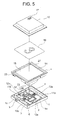
- Figure 5 is an exploded perspective that shows the push-button switch from Figure 1
- Figure 6 is a perspective that shows a base portion from Figure 5 further exploded, a push-button switch that can be used in an elevator car operating panel being shown in this example.
- a circuit board 2 a switch main body 3, a plunger 4, a lever linking mechanism 5 for translating the plunger 4, and an operating segment 6 that presses and operates the switch main body 3, etc., are installed on a base 1,
- the base 1 is configured into shallow box shape in which a low peripheral wall 1a is disposed so as to stand around a rectangular or square bottom surface portion.
- An aperture 1b is disposed centrally on the bottom surface portion of the base 1.
- An aperture 1c is disposed on the peripheral wall 1a.
- the circuit board 2 is disposed on the bottom surface portion of the base 1 so as to face the aperture 1b.
- the circuit board 2 is inserted into the aperture 1b from a rear surface side of the base 1 and is fixed to the base 1.
- An identification plate 33 is affixed to the rear surface of the base 1. The aperture 1b is closed by the identification plate 33.
- the switch main body 3 is mounted onto the circuit board 2 so as to be positioned approximately centrally on the base 1.
- a thin leaf switch is used as the switch main body 3.
- An operating lug 7 is disposed on an upper surface of the switch main body 3.
- a pair of tabular external terminals 8a and 8b are led out from side portions of the switch main body 3. These external terminals 8a and 8b are electrically connected to circuit patterns on the circuit board 2.
- a connector 9 to which external wiring is connected is mounted to an end portion on the circuit board 2.
- the connector 9 passes through the aperture 1c and is exposed outside the base 1.
- the lever linking mechanism 5 has: a pair of lever links 11a and 11b in which a metal wire material is bent into angular C shapes; a pair of joint members 12a and 12b that link the two end portions of the lever links 11a and 11b to each other; and a pair of helical extension springs 13a and 13b for snap action.
- First end portions of the lever links 11a and 11b are pivotably inserted into the joint members 12a.
- Second end portions of the lever links 11a and 11b are also pivotably inserted into the joint members 12b.
- the angle between the lever links 11a and 11b is variable.
- the operating segment 6 is formed into an elongated shape by punching a thick plate metal material.
- Engaging portions 6a and 6b are formed on two end portions of the operating segment 6 by bending.
- the engaging portion 6a is engaged in an intermediate portion of the lever link 11a.
- the engaging portion 6b is engaged in an intermediate portion of the lever link 11b.
- An aperture 6c is disposed on a central portion of the operating segment 6.
- the helical extension spring 13a is disposed between an edge portion of the aperture 6c and the engaging portion 6a
- the helical extension spring 13b is disposed between an edge portion of the aperture 6c and the engaging portion 6b.
- the lever links 11a and 11b are thereby pulled toward each other.
- Notch portions 6d and 6e that accommodate the helical extension springs 13a and 13b are also disposed on the operating segment 6.
- an operating tongue portion 6f is formed into a cantilevered shape on a central portion of the operating segment 6 by cutting out.
- the operating tongue portion 6f is placed in contact with an upper surface (an operating surface) of the operating lug 7.
- upper portion lugs 1d and lower portion lugs 1e are formed on inner surfaces of the peripheral wall 1a.
- the respective lever links 11a and 11b are inserted between upper portion lugs 1d and lower portion lugs 1e, and are pivoted such that the inserted portions function as pivoting points ("p" in Figure 3 ).
- Intermediate portions of the lever links 11a and 11b are also engaged in engaging lugs 4a and 4b that are disposed on the plunger 4.
- the plunger 4 is configured into a shallow rectangular box shape, and is inserted inside the base 1.
- a flat, rectangular illuminating portion 14 is fitted inside the plunger 4.
- a rectangular push-button 15 that is made of a transparent resin is disposed over the illuminating portion 14. The push-button 15 is fitted into the plunger 4 so as to cover the illuminating portion 14.
- a display sheet 16 to which a display that corresponds to the user's request is affixed (in this case, a floor number) is interposed between the illuminating portion 14 and the push-button 15.
- a mark 17 for conveying information to the user by sense of touch is disposed on a portion of a front surface of the push-button 15. In this example, the mark 17 projects outward from the front surface of the push-button 15, and shows the floor number of the corresponding destination floor as the information.
- FIG 7 is a perspective that shows the illuminating portion 14 from Figure 5 further exploded.
- the illuminating portion 14 has: a flat plate-shaped light-guiding plate 18, a main light source portion 19, a mark light source portion 20, first wiring 21, second wiring 22, a light source connector 23, a main diffusing portion 24, a mark diffusing portion 25, a first light source cover 26, and a second light source cover 27.
- the main light source portion 19 and the mark light source portion 20 inject light into the light-guiding plate 18 from side surfaces of the light-guiding plate 18 that face each other.
- the main light source portion 19 has: an elongated first light source circuit board 28; and a plurality of first LEDs 29 that are disposed on the first light source circuit board 28 so as to be spaced apart from each other.
- the first LEDs 29 are arranged in a straight line.
- the mark light source portion 20 has: an elongated second light source circuit board 30; and a plurality of second LEDs 31 that are disposed on the second light source circuit board 30 so as to be spaced apart from each other.
- the second LEDs 31 are arranged in a straight line.
- the first LEDs 29 are disposed over an entire width direction of the light-guiding plate 18, and inject light into the entire light-guiding plate 18.
- the second LEDs 31 are disposed only on a portion of the light-guiding plate 18 in the width direction, i.e., a region in which the mark diffusing portion 25 is disposed, and inject light into the light-guiding plate 18 partially. Consequently, the number of second LEDs 31 is less than the number of first LEDs 29.
- the light source connector 23 is connected to the main light source portion 19 and the mark light source portion 20 so as to have the first and second wiring 21 and 22 interposed.
- the light source connector 23 is connected to a circuit board connector 32 that is disposed on the circuit board 2.
- the main light source portion 19 and the mark light source portion 20 are each switched on and off independently.
- Diffusing sheets that diffuse (scatter) the light that is injected into the light-guiding plate 18 are used as the main diffusing portion 24 and the mark diffusing portion 25.
- the main diffusing portion 24 covers an entire rear surface of the light-guiding plate 18 and side surfaces on which the light source portions 19 and 20 are not disposed.
- the mark diffusing portion 25 is disposed only on a portion of the front surface of the light-guiding plate 18 on which the mark 17 is disposed.
- the mark diffusing portion 25 has a similar shape to the horizontal shape of the mark 17, and is disposed so as to overlap with the mark 17 when viewed from in front.
- Figure 8 is a partial cross section of the illuminating portion 14 from Figure 5 .
- the position of the first LEDs 29 in the thickness direction of the light-guiding plate 18 is similar to that of the main diffusing portion 24.
- the position of the second LEDs 31 in the thickness direction of the light-guiding plate 18 is similar to that of the mark diffusing portion 25.
- the main diffusing portion 24 and the mark diffusing portion 25 are disposed at different positions in the thickness direction of the light-guiding plate 18, and the position of injection of light from the main light source portion 19 to the light-guiding plate 18 and the position of injection of light from the mark light source portion 20 to the light-guiding plate 18 are offset in the thickness direction of the light-guiding plate 18 so as to correspond thereto.
- lever links 11a and 11b are pivoted further, and the intermediate portions of the lever links 11a and 11b are moved closer to the bottom surface of the base 1 than the pivoting points p, the intermediate portions of the lever links 11a and 11b are pulled together by the restoring force of the helical extension springs 13a and 13b.
- the lever links 11a and 11b are thereby deformed to a peak fold posture instantaneously. At this point, resistance to the pressing operation is reduced instantaneously due to a snap action in which the direction of force is reversed, and a clicking sensation is thereby applied to the finger of the user.
- the operating segment 6 is also displaced in a similar direction by the lever linking mechanism 5 performing the snap action and the helical extension springs 13a and 13b being moved toward the bottom surface of the base 1, and the operating lug 7 is depressed by the operating tongue portion 6f, setting the switch main body 3 to an ON state.
- the operating segment 6 is moved away from the bottom surface of the base 1 by the restoring force of the operating lug 7, and the lever linking mechanism 5 is restored to the original valley fold posture by a reverse snap action.
- the plunger 4 is also restored to its original position therewith, and the switch main body 3 is set to an OFF state.
- the switch main body 3 when the switch main body 3 is set to the ON state, the main light source portion 19 is switched on, and light is injected into the light-guiding plate 18 from the main light source portion 19.
- the light that is injected into the light-guiding plate 18 from the main light source portion 19 is scattered by the main diffusing portion 24.
- the entire push-button 15 and display sheet 16 are illuminated thereby, indicating that destination floor registration has been executed.
- the main light source portion 19 is switched off.
- the mark light source portion 20 is constantly switched on regardless of the switching on and off of the main light source portion 19.
- the light that is injected into the light-guiding plate 18 from the mark light source portion 20 is scattered by the mark diffusing portion 25.
- the mark 17 is constantly illuminated thereby, irrespective of the operational state of the switch main body 3.
- a push-button switch of this kind reductions in thickness are enabled while ensuring a clicking sensation, and uniform illumination of the entire control surface can also be achieved. Because the mark 17 is disposed on the push-button 15, and the mark diffusing portion 25 is also disposed on a portion of the light-guiding plate 18 that faces the mark 17, and light is injected into the light-guiding plate 18 from the mark light source portion 20 so as to be directed toward the mark diffusing portion 25, visibility of the mark 17 is improved, and functions can thereby be determined promptly by weak-sighted users, enabling operability to be improved.
- main diffusing portion 24 and the mark diffusing portion 25 are disposed at different positions in the thickness direction of the light-guiding plate 18, interference between light from the main light source portion 19 and light from the mark light source portion 20 can be easily avoided, enabling illumination that uses the main diffusing portion 24 and illumination that uses the mark diffusing portion 25 to be each controlled independently.
- the main light source portion 19 and the mark light source portion 20 are disposed so as to face each other on side surfaces of the light-guiding plate 18 that face each other, reductions in thickness of the illuminating portion 14 can be achieved. Furthermore, because the LEDs 29 and 31 are used in the main light source portion 19 and the mark light source portion 20, reductions in size, power saving, and extension of service life can be achieved. Because the mark diffusing portion 25 has a similar shape to the horizontal shape of the mark 17, and is disposed so as to overlap with the mark 17 when viewed from the front, the shape of the mark 17 can be shown more distinctly, enabling visibility to be improved further.
- Figure 9 is a partial cross section of a push-button switch according to Embodiment 2 of the present invention.
- a mark light source portion 20 is disposed so as to be inclined relative to a light-guiding plate 18. Light from the mark light source portion 20 is thereby emitted so as to be inclined relative to a mark diffusing portion 25.
- First LEDs 29 and second LEDs 31 are disposed at approximately identical positions in a thickness direction of the light-guiding plate 18. Specifically, in Embodiment 1, interference between light from the first and second LEDs 29 and 31 is avoided by offsetting the positions of the first and second LEDs 29 and 31 in the thickness direction of the light-guiding plate 18, but in Embodiment 2, optical interference is avoided by changing an angle of incidence of the light from the mark light source portion 20 into the light-guiding plate 18. The rest of the configuration is similar to that of Embodiment 1.
- the mark light source portion 20 can be prevented from projecting beyond the front surface side of the light-guiding plate 18, further enabling overall reductions in thickness.
- Figure 10 is an exploded perspective that shows an illuminating portion of a push-button switch according to Embodiment 3 of the present invention.
- First and second LEDs 29 and 31 are disposed on a common light source circuit board 34 such that positions in a thickness direction of the light-guiding plate 18 are offset.
- the main light source portion 19 and the mark light source portion 20 are integrated.
- a light source connector 23 is connected to the light source circuit board 34 by means of wiring 35. The rest of the configuration is similar to that of Embodiment 1.
- Figure 11 is an exploded perspective that shows an illuminating portion of a push-button switch according to Embodiment 4 of the present invention.
- the first and second LEDs 29 and 31 are disposed in identical positions in the width direction of the light-guiding plate 18, but in Embodiment 4, positions of first and second LEDs 29 and 31 are offset from each other in a width direction of the light-guiding plate 18.
- the first and second LEDs 29 and 31 are disposed so as to line up in the thickness direction of the light-guiding plate 18 in Embodiment 3, but do not line up in Embodiment 4.
- the rest of the configuration is similar to that of Embodiment 3.
- distances between the first and second LEDs 29 and 31 in the thickness direction of the light-guiding plate 18 can be shortened, further enabling overall reductions in thickness.
- diffusing sheets that are separate from the light-guiding plate 18 are used as the main diffusing portion 24 and the mark diffusing portion 25, but the main diffusing portion 24 and the mark diffusing portion 25 may also be formed on the light-guiding plate 18 itself.
- the main diffusing portion 24 and the mark diffusing portion 25 may also be minute indentations and protrusions that are formed on the light-guiding plate 18 by laser machining (laser marking), for example.
- the diffusing portions may also be formed by applying paint that diffuses light.
- the mark 17 is disposed only at a single position on the front surface of the push-button 15, but may be disposed at a plurality of positions. In that case, it is preferable also to dispose the mark diffusing portion 25 at a plurality of positions.
- the shape of the mark diffusing portion 25 is made similar to the mark 17, but may be another shape if the visibility of the mark 17 can be improved, and may also be a simple rectangular shape or circular shape, for example.
- the mark light source portion 20 is constantly switched on, but may also be set so as to be switched on only when necessary.
- switch main body 3 It is preferable to use a leaf switch that can easily be reduced in thickness as the switch main body 3, but the switch main body 3 is not limited to this, and other types of switch that do not have a clicking action function may also be used.
- LEDs 29 and 31 point light sources
- the light sources are not limited to this, and small-diameter tubular lamps (linear light sources) may also be used, for example.
- the light source circuit boards 28 and 30, or 34 and the circuit board 2 are connected using wiring 21 and 22, or 35 and a connector 23 or 32, but conducting contacting segments that can be elastically deformed may also be projected toward the circuit board 2 from the light source circuit boards 28 and 30, or 34, and electrodes that these conducting contacting segments contact may be disposed on the circuit board 2.
- the main diffusing portion 24 is disposed on a rear surface of the light-guiding plate 18, and the mark diffusing portion 25 is disposed on the front surface of the light-guiding plate 18, but these may also be disposed inside the light-guiding plate 18. Furthermore, the main diffusing portion 24 may also be disposed on a front surface side of the light-guiding plate 18, and the mark diffusing portion 25 disposed on a rear surface side of the light-guiding plate 18.
- the mark 17 is made to stand out from the front surface of the push-button 15, but may also be hollowed out as a recess portion, or may also be flat.
- the push-button switch according to the present invention can also be applied to elevator landing button apparatuses.
- the push-button switch according to the present invention can also be applied to uses other than elevators.
Landscapes
- Push-Button Switches (AREA)
Applications Claiming Priority (1)
| Application Number | Priority Date | Filing Date | Title |
|---|---|---|---|
| PCT/JP2009/052407 WO2010092679A1 (ja) | 2009-02-13 | 2009-02-13 | 押しボタンスイッチ |
Publications (3)
| Publication Number | Publication Date |
|---|---|
| EP2398031A1 true EP2398031A1 (de) | 2011-12-21 |
| EP2398031A4 EP2398031A4 (de) | 2013-12-04 |
| EP2398031B1 EP2398031B1 (de) | 2016-12-14 |
Family
ID=42561531
Family Applications (1)
| Application Number | Title | Priority Date | Filing Date |
|---|---|---|---|
| EP09839999.1A Active EP2398031B1 (de) | 2009-02-13 | 2009-02-13 | Druckknopfschalter |
Country Status (6)
| Country | Link |
|---|---|
| US (1) | US8759699B2 (de) |
| EP (1) | EP2398031B1 (de) |
| JP (1) | JP5121943B2 (de) |
| KR (1) | KR101229151B1 (de) |
| CN (1) | CN102246253B (de) |
| WO (1) | WO2010092679A1 (de) |
Families Citing this family (13)
| Publication number | Priority date | Publication date | Assignee | Title |
|---|---|---|---|---|
| EP2669919A1 (de) * | 2012-05-29 | 2013-12-04 | Siemens Aktiengesellschaft | Elektromechanische Betätigungseinrichtung |
| EP2669918A1 (de) * | 2012-05-29 | 2013-12-04 | Siemens Aktiengesellschaft | Elektromechanisches Befehlsgerät |
| JP2016004767A (ja) * | 2014-06-19 | 2016-01-12 | オムロン株式会社 | 押しボタンスイッチ |
| JP6248825B2 (ja) * | 2014-06-19 | 2017-12-20 | オムロン株式会社 | 押しボタンスイッチ |
| JP6413852B2 (ja) * | 2015-03-10 | 2018-10-31 | オムロン株式会社 | 押しボタンスイッチ |
| US9746168B1 (en) | 2015-10-30 | 2017-08-29 | American Opto Plus Led Corporation | Light-emitting touch buttons |
| JP6447492B2 (ja) * | 2015-12-25 | 2019-01-09 | オムロン株式会社 | 押しボタンスイッチ、押しボタンスイッチユニット |
| CN108022780A (zh) * | 2018-01-24 | 2018-05-11 | 吴江骏达电梯部件有限公司 | 一种超薄电梯按钮 |
| TWI672719B (zh) * | 2018-05-11 | 2019-09-21 | 緯穎科技服務股份有限公司 | 具有開關按鈕之電子裝置及其開關按鈕 |
| CN113661553A (zh) * | 2019-04-10 | 2021-11-16 | 松下知识产权经营株式会社 | 按键开关和照明开关装置 |
| KR102823769B1 (ko) | 2020-08-28 | 2025-06-23 | 엘지전자 주식회사 | 조리기기 및 조리기기의 노브 어셈블리 |
| CN113555240A (zh) * | 2021-05-27 | 2021-10-26 | 宁波昌隆机电有限公司 | 一种亮度均匀的按钮 |
| US12198874B2 (en) * | 2022-02-10 | 2025-01-14 | Crespo Computing Creations Holding Corporation | Magnetic keycap assembly for mechanical keyboard |
Family Cites Families (12)
| Publication number | Priority date | Publication date | Assignee | Title |
|---|---|---|---|---|
| JP4381633B2 (ja) * | 2001-07-02 | 2009-12-09 | 三菱電機株式会社 | エレベータの操作盤 |
| JP4126937B2 (ja) * | 2002-03-13 | 2008-07-30 | オムロン株式会社 | 押釦スイッチ |
| JP2004227997A (ja) | 2003-01-24 | 2004-08-12 | Alps Electric Co Ltd | 照光式タッチパネル |
| CN1260755C (zh) | 2003-07-07 | 2006-06-21 | 欧姆龙株式会社 | 按钮开关 |
| US20060130263A1 (en) * | 2004-12-17 | 2006-06-22 | Coughlin Timothy J | Wiper coupler and wiper assembly incorporating same |
| US8624140B2 (en) * | 2006-07-10 | 2014-01-07 | Fujitsu Component Limited | Key switch and keyboard |
| TWI329483B (en) | 2006-11-30 | 2010-08-21 | Lite On Technology Corp | Thin light-guiding structure and electronic device using the same |
| JP4973302B2 (ja) * | 2006-12-13 | 2012-07-11 | オムロン株式会社 | 押しボタンスイッチ |
| JP4720737B2 (ja) | 2006-12-13 | 2011-07-13 | オムロン株式会社 | リーフスイッチ |
| JP2008251364A (ja) | 2007-03-30 | 2008-10-16 | Shin Etsu Polymer Co Ltd | 操作スイッチ用カバー部材及びその製造方法 |
| US8247714B2 (en) * | 2010-06-08 | 2012-08-21 | Sunrex Technology Corp | Back lighted membrane keyboard with components being secured together by subjecting to ultrasonic welding |
| US8592702B2 (en) * | 2011-11-16 | 2013-11-26 | Chicony Electronics Co., Ltd. | Illuminant keyboard device |
-
2009
- 2009-02-13 US US13/127,376 patent/US8759699B2/en not_active Expired - Fee Related
- 2009-02-13 EP EP09839999.1A patent/EP2398031B1/de active Active
- 2009-02-13 JP JP2010550372A patent/JP5121943B2/ja active Active
- 2009-02-13 CN CN200980149718.4A patent/CN102246253B/zh active Active
- 2009-02-13 WO PCT/JP2009/052407 patent/WO2010092679A1/ja not_active Ceased
- 2009-02-13 KR KR1020117013176A patent/KR101229151B1/ko not_active Expired - Fee Related
Also Published As
| Publication number | Publication date |
|---|---|
| EP2398031A4 (de) | 2013-12-04 |
| US20110209974A1 (en) | 2011-09-01 |
| CN102246253A (zh) | 2011-11-16 |
| WO2010092679A1 (ja) | 2010-08-19 |
| JP5121943B2 (ja) | 2013-01-16 |
| US8759699B2 (en) | 2014-06-24 |
| EP2398031B1 (de) | 2016-12-14 |
| CN102246253B (zh) | 2014-01-01 |
| KR101229151B1 (ko) | 2013-02-01 |
| JPWO2010092679A1 (ja) | 2012-08-16 |
| KR20110082624A (ko) | 2011-07-19 |
Similar Documents
| Publication | Publication Date | Title |
|---|---|---|
| EP2398031B1 (de) | Druckknopfschalter | |
| TW201421511A (zh) | 發光鍵盤 | |
| US9443675B2 (en) | Keyboard | |
| TW201426803A (zh) | 發光鍵盤 | |
| JP5083623B2 (ja) | 押しボタンスイッチ | |
| TWI451290B (zh) | 發光鍵盤 | |
| TW201426804A (zh) | 發光鍵盤 | |
| CN106483786A (zh) | 按键开关装置和图像形成装置 | |
| TW201421513A (zh) | 發光鍵盤 | |
| EP1981049B1 (de) | Schaltvorrichtung mit druckknopf | |
| KR101590145B1 (ko) | 도광 필름을 이용하여 폴리 돔 시트를 구성한 리모컨 입력장치 | |
| JP6413852B2 (ja) | 押しボタンスイッチ | |
| JP4209226B2 (ja) | 照光式プッシュスイッチ装置 | |
| EP4473547B1 (de) | Elektrischer schalter | |
| JP4317042B2 (ja) | 片側シーソつまみの構造 | |
| JPH0743891Y2 (ja) | 照光型メンブレンスイッチ | |
| JP2004227897A (ja) | 押しボタンスイッチの導光構造 | |
| JPH0686234U (ja) | 照光型キー装置 | |
| EP1363302B1 (de) | Schaltvorrichtung | |
| JPH0728790Y2 (ja) | 照光式リモコン入力装置 | |
| JP2001035312A (ja) | 照光式プッシュスイッチ装置 | |
| TWM472236U (zh) | 薄型鍵盤 | |
| JP4239597B2 (ja) | 押しボタンスイッチ | |
| JP2010123420A (ja) | 押しボタン式スイッチ装置 | |
| JPH067125U (ja) | 照光式パネルスイッチ |
Legal Events
| Date | Code | Title | Description |
|---|---|---|---|
| PUAI | Public reference made under article 153(3) epc to a published international application that has entered the european phase |
Free format text: ORIGINAL CODE: 0009012 |
|
| 17P | Request for examination filed |
Effective date: 20110520 |
|
| AK | Designated contracting states |
Kind code of ref document: A1 Designated state(s): AT BE BG CH CY CZ DE DK EE ES FI FR GB GR HR HU IE IS IT LI LT LU LV MC MK MT NL NO PL PT RO SE SI SK TR |
|
| DAX | Request for extension of the european patent (deleted) | ||
| A4 | Supplementary search report drawn up and despatched |
Effective date: 20131031 |
|
| RIC1 | Information provided on ipc code assigned before grant |
Ipc: H01H 13/28 20060101ALI20131025BHEP Ipc: H01H 13/02 20060101AFI20131025BHEP Ipc: H01H 9/18 20060101ALN20131025BHEP Ipc: H01H 13/14 20060101ALN20131025BHEP |
|
| REG | Reference to a national code |
Ref country code: DE Ref legal event code: R079 Ref document number: 602009043149 Country of ref document: DE Free format text: PREVIOUS MAIN CLASS: H01H0013220000 Ipc: H01H0013020000 |
|
| GRAP | Despatch of communication of intention to grant a patent |
Free format text: ORIGINAL CODE: EPIDOSNIGR1 |
|
| RIC1 | Information provided on ipc code assigned before grant |
Ipc: H01H 13/14 20060101ALN20160616BHEP Ipc: H01H 9/18 20060101ALN20160616BHEP Ipc: H01H 13/02 20060101AFI20160616BHEP Ipc: H01H 13/28 20060101ALI20160616BHEP |
|
| RIC1 | Information provided on ipc code assigned before grant |
Ipc: H01H 13/14 20060101ALN20160621BHEP Ipc: H01H 9/18 20060101ALN20160621BHEP Ipc: H01H 13/02 20060101AFI20160621BHEP Ipc: H01H 13/28 20060101ALI20160621BHEP |
|
| INTG | Intention to grant announced |
Effective date: 20160713 |
|
| GRAS | Grant fee paid |
Free format text: ORIGINAL CODE: EPIDOSNIGR3 |
|
| GRAA | (expected) grant |
Free format text: ORIGINAL CODE: 0009210 |
|
| AK | Designated contracting states |
Kind code of ref document: B1 Designated state(s): AT BE BG CH CY CZ DE DK EE ES FI FR GB GR HR HU IE IS IT LI LT LU LV MC MK MT NL NO PL PT RO SE SI SK TR |
|
| REG | Reference to a national code |
Ref country code: GB Ref legal event code: FG4D |
|
| REG | Reference to a national code |
Ref country code: CH Ref legal event code: EP |
|
| REG | Reference to a national code |
Ref country code: IE Ref legal event code: FG4D |
|
| REG | Reference to a national code |
Ref country code: AT Ref legal event code: REF Ref document number: 854262 Country of ref document: AT Kind code of ref document: T Effective date: 20170115 |
|
| REG | Reference to a national code |
Ref country code: DE Ref legal event code: R096 Ref document number: 602009043149 Country of ref document: DE |
|
| PG25 | Lapsed in a contracting state [announced via postgrant information from national office to epo] |
Ref country code: LV Free format text: LAPSE BECAUSE OF FAILURE TO SUBMIT A TRANSLATION OF THE DESCRIPTION OR TO PAY THE FEE WITHIN THE PRESCRIBED TIME-LIMIT Effective date: 20161214 |
|
| REG | Reference to a national code |
Ref country code: LT Ref legal event code: MG4D |
|
| REG | Reference to a national code |
Ref country code: NL Ref legal event code: MP Effective date: 20161214 |
|
| PG25 | Lapsed in a contracting state [announced via postgrant information from national office to epo] |
Ref country code: SE Free format text: LAPSE BECAUSE OF FAILURE TO SUBMIT A TRANSLATION OF THE DESCRIPTION OR TO PAY THE FEE WITHIN THE PRESCRIBED TIME-LIMIT Effective date: 20161214 Ref country code: GR Free format text: LAPSE BECAUSE OF FAILURE TO SUBMIT A TRANSLATION OF THE DESCRIPTION OR TO PAY THE FEE WITHIN THE PRESCRIBED TIME-LIMIT Effective date: 20170315 Ref country code: NO Free format text: LAPSE BECAUSE OF FAILURE TO SUBMIT A TRANSLATION OF THE DESCRIPTION OR TO PAY THE FEE WITHIN THE PRESCRIBED TIME-LIMIT Effective date: 20170314 Ref country code: LT Free format text: LAPSE BECAUSE OF FAILURE TO SUBMIT A TRANSLATION OF THE DESCRIPTION OR TO PAY THE FEE WITHIN THE PRESCRIBED TIME-LIMIT Effective date: 20161214 |
|
| REG | Reference to a national code |
Ref country code: AT Ref legal event code: MK05 Ref document number: 854262 Country of ref document: AT Kind code of ref document: T Effective date: 20161214 |
|
| PG25 | Lapsed in a contracting state [announced via postgrant information from national office to epo] |
Ref country code: FI Free format text: LAPSE BECAUSE OF FAILURE TO SUBMIT A TRANSLATION OF THE DESCRIPTION OR TO PAY THE FEE WITHIN THE PRESCRIBED TIME-LIMIT Effective date: 20161214 Ref country code: HR Free format text: LAPSE BECAUSE OF FAILURE TO SUBMIT A TRANSLATION OF THE DESCRIPTION OR TO PAY THE FEE WITHIN THE PRESCRIBED TIME-LIMIT Effective date: 20161214 Ref country code: BE Free format text: LAPSE BECAUSE OF NON-PAYMENT OF DUE FEES Effective date: 20170228 |
|
| PG25 | Lapsed in a contracting state [announced via postgrant information from national office to epo] |
Ref country code: NL Free format text: LAPSE BECAUSE OF FAILURE TO SUBMIT A TRANSLATION OF THE DESCRIPTION OR TO PAY THE FEE WITHIN THE PRESCRIBED TIME-LIMIT Effective date: 20161214 |
|
| PG25 | Lapsed in a contracting state [announced via postgrant information from national office to epo] |
Ref country code: CZ Free format text: LAPSE BECAUSE OF FAILURE TO SUBMIT A TRANSLATION OF THE DESCRIPTION OR TO PAY THE FEE WITHIN THE PRESCRIBED TIME-LIMIT Effective date: 20161214 Ref country code: SK Free format text: LAPSE BECAUSE OF FAILURE TO SUBMIT A TRANSLATION OF THE DESCRIPTION OR TO PAY THE FEE WITHIN THE PRESCRIBED TIME-LIMIT Effective date: 20161214 Ref country code: EE Free format text: LAPSE BECAUSE OF FAILURE TO SUBMIT A TRANSLATION OF THE DESCRIPTION OR TO PAY THE FEE WITHIN THE PRESCRIBED TIME-LIMIT Effective date: 20161214 Ref country code: RO Free format text: LAPSE BECAUSE OF FAILURE TO SUBMIT A TRANSLATION OF THE DESCRIPTION OR TO PAY THE FEE WITHIN THE PRESCRIBED TIME-LIMIT Effective date: 20161214 Ref country code: IS Free format text: LAPSE BECAUSE OF FAILURE TO SUBMIT A TRANSLATION OF THE DESCRIPTION OR TO PAY THE FEE WITHIN THE PRESCRIBED TIME-LIMIT Effective date: 20170414 |
|
| PG25 | Lapsed in a contracting state [announced via postgrant information from national office to epo] |
Ref country code: PL Free format text: LAPSE BECAUSE OF FAILURE TO SUBMIT A TRANSLATION OF THE DESCRIPTION OR TO PAY THE FEE WITHIN THE PRESCRIBED TIME-LIMIT Effective date: 20161214 Ref country code: BG Free format text: LAPSE BECAUSE OF FAILURE TO SUBMIT A TRANSLATION OF THE DESCRIPTION OR TO PAY THE FEE WITHIN THE PRESCRIBED TIME-LIMIT Effective date: 20170314 Ref country code: PT Free format text: LAPSE BECAUSE OF FAILURE TO SUBMIT A TRANSLATION OF THE DESCRIPTION OR TO PAY THE FEE WITHIN THE PRESCRIBED TIME-LIMIT Effective date: 20170414 Ref country code: IT Free format text: LAPSE BECAUSE OF FAILURE TO SUBMIT A TRANSLATION OF THE DESCRIPTION OR TO PAY THE FEE WITHIN THE PRESCRIBED TIME-LIMIT Effective date: 20161214 Ref country code: AT Free format text: LAPSE BECAUSE OF FAILURE TO SUBMIT A TRANSLATION OF THE DESCRIPTION OR TO PAY THE FEE WITHIN THE PRESCRIBED TIME-LIMIT Effective date: 20161214 Ref country code: ES Free format text: LAPSE BECAUSE OF FAILURE TO SUBMIT A TRANSLATION OF THE DESCRIPTION OR TO PAY THE FEE WITHIN THE PRESCRIBED TIME-LIMIT Effective date: 20161214 Ref country code: BE Free format text: LAPSE BECAUSE OF FAILURE TO SUBMIT A TRANSLATION OF THE DESCRIPTION OR TO PAY THE FEE WITHIN THE PRESCRIBED TIME-LIMIT Effective date: 20161214 |
|
| REG | Reference to a national code |
Ref country code: DE Ref legal event code: R097 Ref document number: 602009043149 Country of ref document: DE |
|
| PG25 | Lapsed in a contracting state [announced via postgrant information from national office to epo] |
Ref country code: MC Free format text: LAPSE BECAUSE OF FAILURE TO SUBMIT A TRANSLATION OF THE DESCRIPTION OR TO PAY THE FEE WITHIN THE PRESCRIBED TIME-LIMIT Effective date: 20161214 |
|
| REG | Reference to a national code |
Ref country code: CH Ref legal event code: PL |
|
| PLBE | No opposition filed within time limit |
Free format text: ORIGINAL CODE: 0009261 |
|
| STAA | Information on the status of an ep patent application or granted ep patent |
Free format text: STATUS: NO OPPOSITION FILED WITHIN TIME LIMIT |
|
| PG25 | Lapsed in a contracting state [announced via postgrant information from national office to epo] |
Ref country code: CH Free format text: LAPSE BECAUSE OF NON-PAYMENT OF DUE FEES Effective date: 20170228 Ref country code: LI Free format text: LAPSE BECAUSE OF NON-PAYMENT OF DUE FEES Effective date: 20170228 |
|
| 26N | No opposition filed |
Effective date: 20170915 |
|
| GBPC | Gb: european patent ceased through non-payment of renewal fee |
Effective date: 20170314 |
|
| REG | Reference to a national code |
Ref country code: IE Ref legal event code: MM4A |
|
| PG25 | Lapsed in a contracting state [announced via postgrant information from national office to epo] |
Ref country code: DK Free format text: LAPSE BECAUSE OF FAILURE TO SUBMIT A TRANSLATION OF THE DESCRIPTION OR TO PAY THE FEE WITHIN THE PRESCRIBED TIME-LIMIT Effective date: 20161214 |
|
| REG | Reference to a national code |
Ref country code: FR Ref legal event code: ST Effective date: 20171031 |
|
| PG25 | Lapsed in a contracting state [announced via postgrant information from national office to epo] |
Ref country code: LU Free format text: LAPSE BECAUSE OF NON-PAYMENT OF DUE FEES Effective date: 20170213 |
|
| PG25 | Lapsed in a contracting state [announced via postgrant information from national office to epo] |
Ref country code: FR Free format text: LAPSE BECAUSE OF NON-PAYMENT OF DUE FEES Effective date: 20170228 |
|
| PG25 | Lapsed in a contracting state [announced via postgrant information from national office to epo] |
Ref country code: SI Free format text: LAPSE BECAUSE OF FAILURE TO SUBMIT A TRANSLATION OF THE DESCRIPTION OR TO PAY THE FEE WITHIN THE PRESCRIBED TIME-LIMIT Effective date: 20161214 Ref country code: IE Free format text: LAPSE BECAUSE OF NON-PAYMENT OF DUE FEES Effective date: 20170213 Ref country code: GB Free format text: LAPSE BECAUSE OF NON-PAYMENT OF DUE FEES Effective date: 20170314 |
|
| PG25 | Lapsed in a contracting state [announced via postgrant information from national office to epo] |
Ref country code: MT Free format text: LAPSE BECAUSE OF NON-PAYMENT OF DUE FEES Effective date: 20170213 |
|
| REG | Reference to a national code |
Ref country code: DE Ref legal event code: R084 Ref document number: 602009043149 Country of ref document: DE |
|
| PG25 | Lapsed in a contracting state [announced via postgrant information from national office to epo] |
Ref country code: HU Free format text: LAPSE BECAUSE OF FAILURE TO SUBMIT A TRANSLATION OF THE DESCRIPTION OR TO PAY THE FEE WITHIN THE PRESCRIBED TIME-LIMIT; INVALID AB INITIO Effective date: 20090213 |
|
| PG25 | Lapsed in a contracting state [announced via postgrant information from national office to epo] |
Ref country code: CY Free format text: LAPSE BECAUSE OF NON-PAYMENT OF DUE FEES Effective date: 20161214 |
|
| PG25 | Lapsed in a contracting state [announced via postgrant information from national office to epo] |
Ref country code: MK Free format text: LAPSE BECAUSE OF FAILURE TO SUBMIT A TRANSLATION OF THE DESCRIPTION OR TO PAY THE FEE WITHIN THE PRESCRIBED TIME-LIMIT Effective date: 20161214 |
|
| PG25 | Lapsed in a contracting state [announced via postgrant information from national office to epo] |
Ref country code: TR Free format text: LAPSE BECAUSE OF FAILURE TO SUBMIT A TRANSLATION OF THE DESCRIPTION OR TO PAY THE FEE WITHIN THE PRESCRIBED TIME-LIMIT Effective date: 20161214 |
|
| P01 | Opt-out of the competence of the unified patent court (upc) registered |
Effective date: 20230512 |
|
| PGFP | Annual fee paid to national office [announced via postgrant information from national office to epo] |
Ref country code: DE Payment date: 20251230 Year of fee payment: 18 |