EP2397638B1 - Antrieb zum Öffnen und/oder Schließen eines beweglichen Flügels einer Tür oder eines Fensters - Google Patents
Antrieb zum Öffnen und/oder Schließen eines beweglichen Flügels einer Tür oder eines Fensters Download PDFInfo
- Publication number
- EP2397638B1 EP2397638B1 EP11169212.5A EP11169212A EP2397638B1 EP 2397638 B1 EP2397638 B1 EP 2397638B1 EP 11169212 A EP11169212 A EP 11169212A EP 2397638 B1 EP2397638 B1 EP 2397638B1
- Authority
- EP
- European Patent Office
- Prior art keywords
- drive
- piston
- valve
- opening
- proportional valve
- Prior art date
- Legal status (The legal status is an assumption and is not a legal conclusion. Google has not performed a legal analysis and makes no representation as to the accuracy of the status listed.)
- Active
Links
Images

Classifications
-
- E—FIXED CONSTRUCTIONS
- E05—LOCKS; KEYS; WINDOW OR DOOR FITTINGS; SAFES
- E05F—DEVICES FOR MOVING WINGS INTO OPEN OR CLOSED POSITION; CHECKS FOR WINGS; WING FITTINGS NOT OTHERWISE PROVIDED FOR, CONCERNED WITH THE FUNCTIONING OF THE WING
- E05F3/00—Closers or openers with braking devices, e.g. checks; Construction of pneumatic or liquid braking devices
- E05F3/04—Closers or openers with braking devices, e.g. checks; Construction of pneumatic or liquid braking devices with liquid piston brakes
- E05F3/10—Closers or openers with braking devices, e.g. checks; Construction of pneumatic or liquid braking devices with liquid piston brakes with a spring, other than a torsion spring, and a piston, the axes of which are the same or lie in the same direction
- E05F3/102—Closers or openers with braking devices, e.g. checks; Construction of pneumatic or liquid braking devices with liquid piston brakes with a spring, other than a torsion spring, and a piston, the axes of which are the same or lie in the same direction with rack-and-pinion transmission between driving shaft and piston within the closer housing
-
- E—FIXED CONSTRUCTIONS
- E05—LOCKS; KEYS; WINDOW OR DOOR FITTINGS; SAFES
- E05F—DEVICES FOR MOVING WINGS INTO OPEN OR CLOSED POSITION; CHECKS FOR WINGS; WING FITTINGS NOT OTHERWISE PROVIDED FOR, CONCERNED WITH THE FUNCTIONING OF THE WING
- E05F3/00—Closers or openers with braking devices, e.g. checks; Construction of pneumatic or liquid braking devices
- E05F3/04—Closers or openers with braking devices, e.g. checks; Construction of pneumatic or liquid braking devices with liquid piston brakes
- E05F3/12—Special devices controlling the circulation of the liquid, e.g. valve arrangement
-
- E—FIXED CONSTRUCTIONS
- E05—LOCKS; KEYS; WINDOW OR DOOR FITTINGS; SAFES
- E05F—DEVICES FOR MOVING WINGS INTO OPEN OR CLOSED POSITION; CHECKS FOR WINGS; WING FITTINGS NOT OTHERWISE PROVIDED FOR, CONCERNED WITH THE FUNCTIONING OF THE WING
- E05F15/00—Power-operated mechanisms for wings
- E05F15/50—Power-operated mechanisms for wings using fluid-pressure actuators
- E05F15/53—Power-operated mechanisms for wings using fluid-pressure actuators for swinging wings
-
- E—FIXED CONSTRUCTIONS
- E05—LOCKS; KEYS; WINDOW OR DOOR FITTINGS; SAFES
- E05Y—INDEXING SCHEME ASSOCIATED WITH SUBCLASSES E05D AND E05F, RELATING TO CONSTRUCTION ELEMENTS, ELECTRIC CONTROL, POWER SUPPLY, POWER SIGNAL OR TRANSMISSION, USER INTERFACES, MOUNTING OR COUPLING, DETAILS, ACCESSORIES, AUXILIARY OPERATIONS NOT OTHERWISE PROVIDED FOR, APPLICATION THEREOF
- E05Y2900/00—Application of doors, windows, wings or fittings thereof
- E05Y2900/10—Application of doors, windows, wings or fittings thereof for buildings or parts thereof
- E05Y2900/13—Type of wing
- E05Y2900/132—Doors
Definitions
- the invention relates to a drive for opening and / or closing a movable wing of a door or a window according to the preamble of patent claim 1.
- a drive for opening and / or closing a movable wing of a door or the like has a driven shaft designed as an output member, which can be coupled via a power transmission device or directly to the wing of the door.
- a displaceably guided in a cylinder piston is coupled with the driven member movement.
- a damping device serves to damp the movement of the piston in at least one direction.
- a hydraulic pump can be driven by a drive motor. The piston divides the cylinder into at least two pressure chambers. The pressure side of the hydraulic pump is connected via at least one channel section with at least one pressure chamber.
- the damping device comprises in this drive a plurality of throttle valves, which are manually adjustable and each associated with only one direction of movement of the piston.
- a plurality of throttle valves which are manually adjustable and each associated with only one direction of movement of the piston.
- several valves are required per direction of movement, which cooperate via separate channel mouths with the respective pressure chamber.
- This solution is expensive to manufacture, as in the cylinder a variety of valve seats and channels are implanten.
- changes in the damping characteristic are only directly at the installation location of the drive by manual
- the invention has for its object to provide a drive with a simple structure, which allows flexible adaptation of the damping characteristic.
- the damping device has at least one proportional valve.
- the structure of the drive is significantly simplified, since per pressure chamber in principle sufficient for a single channel in this einmündender.
- an extremely flexible adaptation of the damping characteristic is possible, since the proportional valve is independent of the piston position in principle infinitely adjustable, and this can also happen automatically and / or remotely from the installation of the drive.
- a control device for controlling the drive motor In automatic drives usually a control device for controlling the drive motor is provided.
- the control device controls - triggered by sensor signals and / or switch operations - the energy supply to the drive motor depending on a presettable sequence program and / or measured characteristics.
- the proportional valve is controllable by this controller, whereby e.g. the flow cross-section of the proportional valve can be set directly as a function of the currently measured parameters in the sense of a control.
- At least one shut-off valve is arranged between the pressure chamber and the proportional valve and at least one change-over valve can be arranged.
- the proportional valve can be at least partially in both directions of movement of the piston, ie at least over a portion of each direction of movement be effective damping, ie a single proportional valve may be sufficient for both directions of movement.
- the Fig. 1 shows a mounted on a revolving door drive 1.
- the revolving door has a door leaf 6, which is mounted via hinges 8 about a vertical axis of rotation rotatably mounted on a stationary door frame 7.
- the housing 2 of the drive 1 is arranged in the upper horizontal region of the door frame 7.
- In the housing 2 of the drive 1 designed as an output shaft output member 3 is mounted with a vertical axis of rotation, wherein the ends of the output member 3 protrude from the housing 2.
- the door leaf 6 facing the end of the driven member 3, the one end of a trained as sliding arm power transmission element 4 is rotatably mounted.
- the other end of the power transmission element 4 is guided linearly displaceable by means of a slider in a mounted in the region of the upper horizontal edge of the door leaf 6 slide rail 5.
- a rotational movement of the output member 3 of the drive 1 causes the power transmission element 4 is pivoted and moves over the slide guided in the slide 5, the door 6, and vice versa.
- the drive 1 has a control device, not shown here, which controls the movement of the drive, e.g. depending on sensor signals and / or manual switching operations.
- the control device may comprise a memory device in which the parameters required for operating the drive 1 can be stored non-volatilely.
- the drive 1 is designed as an electro-hydraulic drive.
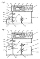
- the structural design of the drive 1 is in the Fig. 2 to 4 shown schematically in three embodiments. For all three embodiments, the following applies:
- a piston 12 is guided linearly displaceable.
- the piston 12 preferably divides the interior of the cylinder 9 in a liquid-tight manner into two pressure chambers 15, 16.
- the cylinder 9 has a cover 10 on the front side.
- the piston 12 has a piston interior with a toothing 13.
- the toothing 13 meshes with a rotatably arranged on the output member 3 pinion 11, so that a displacement of the piston 12 causes rotation of the output member 3, and vice versa.
- a drive motor 18 designed as an electric motor and a hydraulic pump 19 operatively connected via a clutch to the drive motor 18 are arranged.
- the suction side of the hydraulic pump 19 is connected via a channel section 22 with a pressure medium reservoir 17.
- the pressure medium reservoir 17 may contain not only a hydraulic medium but also a pressure compensation device, for example a closed air cushion which can be compressed when the temperature increases.
- the pressure side of the hydraulic pump 19 is connected via a channel section 29, which in a first branch in a channel portion 28 passes, a check valve 35, a channel portion 27, which merges into a second branch in a channel portion 26, a check valve 34 and a channel portion 20 connected to the left in the drawing pressure chamber 15.
- the check valve 35 is open at a flow direction of the hydraulic medium to the left pressure chamber 15 and closes as soon as the flow direction of the hydraulic medium is reversed, that is, the hydraulic medium from the left pressure chamber 15 flows out.
- the shut-off valve 34 is designed as an electrically switchable solenoid valve and is then controlled by the control device of the drive 1 in the sense of an opening when a movement of the piston 12 is to take place.
- the outgoing from the suction side of the hydraulic pump 19 channel section 29 is also in the first branch in a further channel section 30, which in turn via a pressure relief valve 36 and a channel section 23 opens into the pressure medium reservoir 17.
- a triggered by the control device energization of the drive motor 18 causes its rotation and thus sets via the clutch and the hydraulic pump 19 in operation, so that the hydraulic pump 19, the hydraulic fluid from the pressure fluid reservoir 17 through the then open check valve 35 and then also open shut-off valve 34 promotes the left pressure chamber 15.
- the concomitant increase in pressure of the hydraulic medium in the left pressure chamber 15 causes, under compression of the spring 14, a displacement of the piston 12 to the right, which on the pinion 11, the output member 3, the power transmission element 4 and the slide 5 reaches an opening movement of the door leaf 6 becomes.
- the reaching of the open position of the door leaf 6 is detected by a corresponding encoder and the drive motor 18 then turned off.
- shut-off valve 34 If the shut-off valve 34 is closed immediately after switching off the drive motor 18, then the hydraulic medium then located in the left pressure chamber 15 can not flow out of this, so that the acted upon by the tensioned spring 14 piston 12 can not move to the left and thus the Door leaf 6 is detected in the appropriate position. If the shut-off valve 34 is then opened when the hydraulic pump 19 is stationary, the pressure of the hydraulic medium produced by the spring-loaded piston 12 in the pressure chamber and in the channel sections 20, 26 and 27 causes the check valve 35 to close so that the hydraulic medium does not return to the pressure side the hydraulic pump 19 can flow. Instead, the hydraulic medium flows via a further, starting from the second branch channel section 31 back to the pressure medium reservoir 17. The course of the outflowing hydraulic medium in this case differs between the individual embodiments and will therefore be explained later.
- the first proportional valve 37 is associated with the closing damping and lies in the flow path formed by the channel sections 20, 26, 31, 24, through which the hydraulic medium from the left pressure chamber 15 flows into the pressure medium reservoir 17, when the piston 12 under relaxation of the spring 14th moved to the left.
- the flow cross-section of the proportional valve 37 is in principle infinitely adjustable by control signals of the control device, so that can be realized depending on certain parameters course of the closing loss. For example, a speed profile for the closing movement of the door leaf 6 can be stored in the control device whose setpoints are the basis for controlling the actual values detected by an encoder, and accordingly the flow cross section of the first proportional valve 37 is increased if the closing speed of the door leaf 6 is below the setpoint , and correspondingly reduced, when the closing speed exceeds the set value.
- the opening angle-dependent speed profile for the closing movement of the door leaf 6 may have a so-called "end impact" to overcome the mechanical resistance of seals and / or a latch by shortly before reaching the closed position of the door leaf 6 of the flow cross-section of the first proportional valve 37 is increased and thus the Closing speed of the door leaf 6 increased accordingly.
- the second proportional valve 38 is associated with the opening damping when caused by the operation of the hydraulic pump 19 opening the door leaf 6.
- a part of the hydraulic medium located in the right-hand pressure chamber 16 is displaced therefrom and flows off into a channel section 21, to which the second proportional valve 38 adjoins.
- the hydraulic medium After flowing through the second proportional valve 38, the hydraulic medium then flows through a further channel section 25 into the pressure medium reservoir 17.
- the flow cross section of the second proportional valve 38 is steplessly adjustable in principle by control signals of the control device, so that a course of the opening damping dependent on certain parameters can be realized.
- a speed profile for the opening movement of the door leaf 6 can be stored in the control device whose setpoints are the basis of a regulation of the actual values detected by an encoder, and accordingly the flow cross-section of the second proportional valve 38 is increased if the opening speed of the door leaf 6 is below the setpoint , and correspondingly reduced, when the opening speed exceeds the set value.
- the first proportional valve 37 may be completely closed, so that the then funded by the hydraulic pump 19 from the pressure fluid reservoir 17 hydraulic medium does not return via the channel sections 31, 24 in the pressure fluid reservoir 17, but through the channel sections 26, 20 in the left pressure chamber 15 of the cylinder 9 flows and the opening damping is influenced solely by the second proportional valve 38.
- the first proportional valve 37 can also be used to influence the opening damping by dividing the hydraulic medium delivered by the hydraulic pump 19 from the pressure medium reservoir 17 into the branching channel sections 31, 26 by slightly opening the flow cross section of the first proportional valve 37 ,
- a operated at a constant speed hydraulic pump 19 may be used, wherein nevertheless a sensitive control of the movement of the drive 1 is achieved by the two proportional valves 37, 38.
- the only proportional valve 37 in this embodiment is associated with the closing damping and lies in the flow path formed by the channel sections 20, 26, 31, 24, through which the hydraulic medium from the left pressure chamber 15 flows into the pressure medium reservoir 17, when the piston 12 under relaxation the spring 14 moves to the left.
- This functionality corresponds to that of the embodiment described above Fig. 2 ,
- the movement sequence of the opening movement is influenced by a controllable hydraulic pump 19, ie, for example, a speed profile for the opening movement of the door leaf 6 can be stored in the control device whose setpoints are the basis of a regulation of the actual values detected by a transmitter, and the speed of the hydraulic pump accordingly becomes 19 increases when the opening speed of the door 6 under the setpoint, and correspondingly reduced, when the opening speed exceeds the setpoint.
- the proportional valve 37 can also be used to influence the opening damping, by dividing the hydraulic medium delivered by the hydraulic pump 19 from the pressure medium reservoir 17 into the branching channel sections 31, 26 by slightly opening the flow cross section of the proportional valve 37.
- the only proportional valve 37 in this embodiment is assigned to both the opening and the closing damping.
- the effective during opening or closing flow paths for the hydraulic medium correspond in principle to that for the embodiment according to Fig. 2 described flow paths.
- a switching valve 39 is provided, which can be controlled by the control device.
- the switching position of the switching valve 39 shown in the figure corresponds to the opening operation of the drive during operation of the hydraulic pump 19, so that the proportional valve 37 is in the defined by the channel sections 21, 32, 24 outflow of the hydraulic medium from the right pressure chamber 16 in the pressure fluid reservoir 17.
- the proportional valve 37 is associated with the closing damping and then lies in the defined by the channel sections 20, 26, 31, 32, 24 drainage path of the hydraulic medium from the left pressure chamber 15 in the pressure medium reservoir 17th
Landscapes
- Power-Operated Mechanisms For Wings (AREA)
- Fluid-Damping Devices (AREA)
Priority Applications (1)
| Application Number | Priority Date | Filing Date | Title |
|---|---|---|---|
| PL11169212T PL2397638T3 (pl) | 2010-06-21 | 2011-06-09 | Napęd do otwierania i/lub zamykania ruchomego skrzydła drzwi albo okna |
Applications Claiming Priority (1)
| Application Number | Priority Date | Filing Date | Title |
|---|---|---|---|
| DE102010030303.8A DE102010030303B4 (de) | 2010-06-21 | 2010-06-21 | Antrieb zum Öffnen und/oder Schließen eines beweglichen Flügels einer Tür oder eines Fensters |
Publications (3)
| Publication Number | Publication Date |
|---|---|
| EP2397638A2 EP2397638A2 (de) | 2011-12-21 |
| EP2397638A3 EP2397638A3 (de) | 2013-09-25 |
| EP2397638B1 true EP2397638B1 (de) | 2015-07-29 |
Family
ID=44484021
Family Applications (1)
| Application Number | Title | Priority Date | Filing Date |
|---|---|---|---|
| EP11169212.5A Active EP2397638B1 (de) | 2010-06-21 | 2011-06-09 | Antrieb zum Öffnen und/oder Schließen eines beweglichen Flügels einer Tür oder eines Fensters |
Country Status (5)
| Country | Link |
|---|---|
| EP (1) | EP2397638B1 (pl) |
| DE (1) | DE102010030303B4 (pl) |
| DK (1) | DK2397638T3 (pl) |
| ES (1) | ES2548529T3 (pl) |
| PL (1) | PL2397638T3 (pl) |
Families Citing this family (6)
| Publication number | Priority date | Publication date | Assignee | Title |
|---|---|---|---|---|
| EP3034890B1 (de) | 2014-12-17 | 2019-06-12 | dormakaba Deutschland GmbH | Hydraulikventil und Antriebssteuereinheit, umfassend ein derartiges Hydraulikventil |
| CN107845966A (zh) * | 2017-10-20 | 2018-03-27 | 杭州万禾电力科技有限公司 | 一种景观式液压开启式户外开关站 |
| DK3546684T3 (da) * | 2018-03-27 | 2021-01-18 | Dormakaba Deutschland Gmbh | Dørdrev |
| DE102018210277B4 (de) | 2018-06-25 | 2021-03-18 | Geze Gmbh | Ventil |
| CN114592764A (zh) * | 2020-12-05 | 2022-06-07 | 北京机械设备研究所 | 一种基于液压缸的保温舱盖控制系统和方法 |
| CN112878846A (zh) * | 2021-01-15 | 2021-06-01 | 湖北三江航天万峰科技发展有限公司 | 一种保温舱舱门开关装置及其开、关舱门的方法 |
Family Cites Families (4)
| Publication number | Priority date | Publication date | Assignee | Title |
|---|---|---|---|---|
| FI63622C (fi) * | 1979-02-01 | 1983-07-11 | Waertsilae Oy Ab | Doerrmanoevreringssystem |
| DE3202966A1 (de) | 1982-01-29 | 1983-08-11 | Geze Gmbh, 7250 Leonberg | Elektrohydraulische antriebseinheit fuer fluegel von tueren o.dgl. |
| DE4002747C3 (de) * | 1990-01-31 | 2002-09-05 | Geze Gmbh | Elektrohydraulische Antriebseinheit |
| DE102008060041A1 (de) * | 2008-12-02 | 2010-06-17 | Daimler Ag | Antriebseinrichtung für eine Tür und Verfahren zum Betreiben einer Antriebseinrichtung |
-
2010
- 2010-06-21 DE DE102010030303.8A patent/DE102010030303B4/de active Active
-
2011
- 2011-06-09 ES ES11169212.5T patent/ES2548529T3/es active Active
- 2011-06-09 EP EP11169212.5A patent/EP2397638B1/de active Active
- 2011-06-09 DK DK11169212.5T patent/DK2397638T3/en active
- 2011-06-09 PL PL11169212T patent/PL2397638T3/pl unknown
Also Published As
| Publication number | Publication date |
|---|---|
| DE102010030303A1 (de) | 2011-12-22 |
| EP2397638A3 (de) | 2013-09-25 |
| EP2397638A2 (de) | 2011-12-21 |
| PL2397638T3 (pl) | 2015-12-31 |
| ES2548529T3 (es) | 2015-10-19 |
| DE102010030303B4 (de) | 2014-02-20 |
| DK2397638T3 (en) | 2015-09-28 |
Similar Documents
| Publication | Publication Date | Title |
|---|---|---|
| DE4323150B4 (de) | Drehtürantrieb | |
| EP2397638B1 (de) | Antrieb zum Öffnen und/oder Schließen eines beweglichen Flügels einer Tür oder eines Fensters | |
| DE102011006878B4 (de) | Türschließer | |
| DE102010000556A1 (de) | Hubtor mit einer beweglichen Torblattführung | |
| EP0764752A2 (de) | Schliessvorrichtung für einen Flügel eines Fensters, einer Tür oder dergleichen | |
| DE10324127C5 (de) | Hydraulischer Türantrieb | |
| EP0324075B1 (de) | Vorrichtung zur Regelung der Schliessfolge von zweiflügeligen Türen | |
| DE3941711B4 (de) | Vorrichtung zur Regelung der Schließfolge von zweiflügeligen Türen | |
| EP2679756B1 (de) | Antrieb zum Öffnen und/oder Schließen eines beweglichen Flügels einer Tür oder eines Fensters sowie Verfahren zum Betrieb dieses Antriebs | |
| DE102018210277B4 (de) | Ventil | |
| DE102011078397B3 (de) | Antrieb zum Öffnen und/oder Schließen eines beweglichen Flügels einer Tür oder eines Fensters | |
| DE102011078396B4 (de) | Antrieb zum Öffnen und/oder Schließen eines beweglichen Flügels einer Tür oder eines Fensters | |
| DE10329562B4 (de) | Elektrohydraulischer Antrieb zum Öffnen und Schließen eines bewegbaren Flügels | |
| DE10261224B3 (de) | Elektrohydraulischer Drehflügeltürantrieb | |
| DE19607878B4 (de) | Drehtürantrieb | |
| DE4323151C5 (de) | Drehtürantrieb | |
| EP3070246A1 (de) | Haltevorrichtung für das halten eines schwenkbaren türflügels | |
| DE10361085B4 (de) | Hydraulisch-mechanische Schließfolgeregelung | |
| DE1281870B (de) | Einrichtung zum Verstellen von beweglichen Teilen an Kraftfahrzeugen durch eine Hilfskraft, insbesondere zum OEffnen und Schliessen der Kraftfahrzeugfenster | |
| DE102011050999A1 (de) | Hydraulische Kraftübertragungseinheit für Drehflügelbetätiger sowie damit ausgestattete Drehflügelbetätiger | |
| DE102004063513A1 (de) | Türbaugruppe für ein Kraftfahrzeug | |
| EP1620626B2 (de) | Hydraulisch-mechanische schliessfolgerelung | |
| EP1995405B1 (de) | Schiebeflügelanlage | |
| EP2540944A2 (de) | Antrieb für einen Flügel einer Tür oder dergl. | |
| DE3313310A1 (de) | Anordnung zum oeffnen von insbesondere pneumatisch angetriebenen tueren schienengebundener personenwagen |
Legal Events
| Date | Code | Title | Description |
|---|---|---|---|
| AK | Designated contracting states |
Kind code of ref document: A2 Designated state(s): AL AT BE BG CH CY CZ DE DK EE ES FI FR GB GR HR HU IE IS IT LI LT LU LV MC MK MT NL NO PL PT RO RS SE SI SK SM TR |
|
| AX | Request for extension of the european patent |
Extension state: BA ME |
|
| PUAI | Public reference made under article 153(3) epc to a published international application that has entered the european phase |
Free format text: ORIGINAL CODE: 0009012 |
|
| PUAL | Search report despatched |
Free format text: ORIGINAL CODE: 0009013 |
|
| AK | Designated contracting states |
Kind code of ref document: A3 Designated state(s): AL AT BE BG CH CY CZ DE DK EE ES FI FR GB GR HR HU IE IS IT LI LT LU LV MC MK MT NL NO PL PT RO RS SE SI SK SM TR |
|
| AX | Request for extension of the european patent |
Extension state: BA ME |
|
| RIC1 | Information provided on ipc code assigned before grant |
Ipc: E05F 15/04 20060101ALN20130822BHEP Ipc: E05F 3/10 20060101AFI20130822BHEP Ipc: E05F 3/12 20060101ALI20130822BHEP |
|
| 17P | Request for examination filed |
Effective date: 20140320 |
|
| RBV | Designated contracting states (corrected) |
Designated state(s): AL AT BE BG CH CY CZ DE DK EE ES FI FR GB GR HR HU IE IS IT LI LT LU LV MC MK MT NL NO PL PT RO RS SE SI SK SM TR |
|
| 17Q | First examination report despatched |
Effective date: 20140530 |
|
| GRAP | Despatch of communication of intention to grant a patent |
Free format text: ORIGINAL CODE: EPIDOSNIGR1 |
|
| INTG | Intention to grant announced |
Effective date: 20150325 |
|
| RIC1 | Information provided on ipc code assigned before grant |
Ipc: E05F 3/10 20060101AFI20150313BHEP Ipc: E05F 15/53 20150101ALN20150313BHEP Ipc: E05F 3/12 20060101ALI20150313BHEP |
|
| GRAS | Grant fee paid |
Free format text: ORIGINAL CODE: EPIDOSNIGR3 |
|
| GRAA | (expected) grant |
Free format text: ORIGINAL CODE: 0009210 |
|
| AK | Designated contracting states |
Kind code of ref document: B1 Designated state(s): AL AT BE BG CH CY CZ DE DK EE ES FI FR GB GR HR HU IE IS IT LI LT LU LV MC MK MT NL NO PL PT RO RS SE SI SK SM TR |
|
| REG | Reference to a national code |
Ref country code: GB Ref legal event code: FG4D Free format text: NOT ENGLISH |
|
| REG | Reference to a national code |
Ref country code: CH Ref legal event code: EP |
|
| REG | Reference to a national code |
Ref country code: AT Ref legal event code: REF Ref document number: 739442 Country of ref document: AT Kind code of ref document: T Effective date: 20150815 |
|
| REG | Reference to a national code |
Ref country code: IE Ref legal event code: FG4D Free format text: LANGUAGE OF EP DOCUMENT: GERMAN |
|
| REG | Reference to a national code |
Ref country code: DE Ref legal event code: R096 Ref document number: 502011007438 Country of ref document: DE |
|
| REG | Reference to a national code |
Ref country code: DK Ref legal event code: T3 Effective date: 20150921 |
|
| REG | Reference to a national code |
Ref country code: SE Ref legal event code: TRGR |
|
| REG | Reference to a national code |
Ref country code: ES Ref legal event code: FG2A Ref document number: 2548529 Country of ref document: ES Kind code of ref document: T3 Effective date: 20151019 |
|
| REG | Reference to a national code |
Ref country code: NL Ref legal event code: FP |
|
| REG | Reference to a national code |
Ref country code: DE Ref legal event code: R108 Ref document number: 502011007438 Country of ref document: DE |
|
| RBV | Designated contracting states (corrected) |
Designated state(s): AL AT BE BG CH CY CZ DK EE ES FI FR GB GR HR HU IE IS IT LI LT LU LV MC MK MT NL NO PL PT RO RS SE SI SK SM TR |
|
| REG | Reference to a national code |
Ref country code: NO Ref legal event code: T2 Effective date: 20150729 Ref country code: LT Ref legal event code: MG4D |
|
| REG | Reference to a national code |
Ref country code: PL Ref legal event code: T3 |
|
| REG | Reference to a national code |
Ref country code: DE Ref legal event code: R107 Ref document number: 502011007438 Country of ref document: DE |
|
| PG25 | Lapsed in a contracting state [announced via postgrant information from national office to epo] |
Ref country code: GR Free format text: LAPSE BECAUSE OF FAILURE TO SUBMIT A TRANSLATION OF THE DESCRIPTION OR TO PAY THE FEE WITHIN THE PRESCRIBED TIME-LIMIT Effective date: 20151030 Ref country code: LT Free format text: LAPSE BECAUSE OF FAILURE TO SUBMIT A TRANSLATION OF THE DESCRIPTION OR TO PAY THE FEE WITHIN THE PRESCRIBED TIME-LIMIT Effective date: 20150729 Ref country code: LV Free format text: LAPSE BECAUSE OF FAILURE TO SUBMIT A TRANSLATION OF THE DESCRIPTION OR TO PAY THE FEE WITHIN THE PRESCRIBED TIME-LIMIT Effective date: 20150729 |
|
| PG25 | Lapsed in a contracting state [announced via postgrant information from national office to epo] |
Ref country code: IS Free format text: LAPSE BECAUSE OF FAILURE TO SUBMIT A TRANSLATION OF THE DESCRIPTION OR TO PAY THE FEE WITHIN THE PRESCRIBED TIME-LIMIT Effective date: 20151129 Ref country code: PT Free format text: LAPSE BECAUSE OF FAILURE TO SUBMIT A TRANSLATION OF THE DESCRIPTION OR TO PAY THE FEE WITHIN THE PRESCRIBED TIME-LIMIT Effective date: 20151130 Ref country code: RS Free format text: LAPSE BECAUSE OF FAILURE TO SUBMIT A TRANSLATION OF THE DESCRIPTION OR TO PAY THE FEE WITHIN THE PRESCRIBED TIME-LIMIT Effective date: 20150729 Ref country code: HR Free format text: LAPSE BECAUSE OF FAILURE TO SUBMIT A TRANSLATION OF THE DESCRIPTION OR TO PAY THE FEE WITHIN THE PRESCRIBED TIME-LIMIT Effective date: 20150729 |
|
| PG25 | Lapsed in a contracting state [announced via postgrant information from national office to epo] |
Ref country code: SK Free format text: LAPSE BECAUSE OF FAILURE TO SUBMIT A TRANSLATION OF THE DESCRIPTION OR TO PAY THE FEE WITHIN THE PRESCRIBED TIME-LIMIT Effective date: 20150729 Ref country code: EE Free format text: LAPSE BECAUSE OF FAILURE TO SUBMIT A TRANSLATION OF THE DESCRIPTION OR TO PAY THE FEE WITHIN THE PRESCRIBED TIME-LIMIT Effective date: 20150729 Ref country code: CZ Free format text: LAPSE BECAUSE OF FAILURE TO SUBMIT A TRANSLATION OF THE DESCRIPTION OR TO PAY THE FEE WITHIN THE PRESCRIBED TIME-LIMIT Effective date: 20150729 |
|
| PG25 | Lapsed in a contracting state [announced via postgrant information from national office to epo] |
Ref country code: RO Free format text: LAPSE BECAUSE OF FAILURE TO SUBMIT A TRANSLATION OF THE DESCRIPTION OR TO PAY THE FEE WITHIN THE PRESCRIBED TIME-LIMIT Effective date: 20150729 |
|
| PLBE | No opposition filed within time limit |
Free format text: ORIGINAL CODE: 0009261 |
|
| STAA | Information on the status of an ep patent application or granted ep patent |
Free format text: STATUS: NO OPPOSITION FILED WITHIN TIME LIMIT |
|
| REG | Reference to a national code |
Ref country code: FR Ref legal event code: PLFP Year of fee payment: 6 |
|
| 26N | No opposition filed |
Effective date: 20160502 |
|
| PG25 | Lapsed in a contracting state [announced via postgrant information from national office to epo] |
Ref country code: SI Free format text: LAPSE BECAUSE OF FAILURE TO SUBMIT A TRANSLATION OF THE DESCRIPTION OR TO PAY THE FEE WITHIN THE PRESCRIBED TIME-LIMIT Effective date: 20150729 |
|
| PG25 | Lapsed in a contracting state [announced via postgrant information from national office to epo] |
Ref country code: MC Free format text: LAPSE BECAUSE OF FAILURE TO SUBMIT A TRANSLATION OF THE DESCRIPTION OR TO PAY THE FEE WITHIN THE PRESCRIBED TIME-LIMIT Effective date: 20150729 |
|
| REG | Reference to a national code |
Ref country code: FR Ref legal event code: PLFP Year of fee payment: 7 |
|
| PG25 | Lapsed in a contracting state [announced via postgrant information from national office to epo] |
Ref country code: SM Free format text: LAPSE BECAUSE OF FAILURE TO SUBMIT A TRANSLATION OF THE DESCRIPTION OR TO PAY THE FEE WITHIN THE PRESCRIBED TIME-LIMIT Effective date: 20150729 Ref country code: HU Free format text: LAPSE BECAUSE OF FAILURE TO SUBMIT A TRANSLATION OF THE DESCRIPTION OR TO PAY THE FEE WITHIN THE PRESCRIBED TIME-LIMIT; INVALID AB INITIO Effective date: 20110609 Ref country code: CY Free format text: LAPSE BECAUSE OF FAILURE TO SUBMIT A TRANSLATION OF THE DESCRIPTION OR TO PAY THE FEE WITHIN THE PRESCRIBED TIME-LIMIT Effective date: 20150729 |
|
| REG | Reference to a national code |
Ref country code: FR Ref legal event code: PLFP Year of fee payment: 8 |
|
| PG25 | Lapsed in a contracting state [announced via postgrant information from national office to epo] |
Ref country code: MK Free format text: LAPSE BECAUSE OF FAILURE TO SUBMIT A TRANSLATION OF THE DESCRIPTION OR TO PAY THE FEE WITHIN THE PRESCRIBED TIME-LIMIT Effective date: 20150729 Ref country code: MT Free format text: LAPSE BECAUSE OF FAILURE TO SUBMIT A TRANSLATION OF THE DESCRIPTION OR TO PAY THE FEE WITHIN THE PRESCRIBED TIME-LIMIT Effective date: 20150729 Ref country code: TR Free format text: LAPSE BECAUSE OF FAILURE TO SUBMIT A TRANSLATION OF THE DESCRIPTION OR TO PAY THE FEE WITHIN THE PRESCRIBED TIME-LIMIT Effective date: 20150729 |
|
| PG25 | Lapsed in a contracting state [announced via postgrant information from national office to epo] |
Ref country code: BG Free format text: LAPSE BECAUSE OF FAILURE TO SUBMIT A TRANSLATION OF THE DESCRIPTION OR TO PAY THE FEE WITHIN THE PRESCRIBED TIME-LIMIT Effective date: 20150729 |
|
| PG25 | Lapsed in a contracting state [announced via postgrant information from national office to epo] |
Ref country code: AL Free format text: LAPSE BECAUSE OF FAILURE TO SUBMIT A TRANSLATION OF THE DESCRIPTION OR TO PAY THE FEE WITHIN THE PRESCRIBED TIME-LIMIT Effective date: 20150729 |
|
| P01 | Opt-out of the competence of the unified patent court (upc) registered |
Effective date: 20230510 |
|
| PGFP | Annual fee paid to national office [announced via postgrant information from national office to epo] |
Ref country code: NL Payment date: 20230620 Year of fee payment: 13 Ref country code: IE Payment date: 20230620 Year of fee payment: 13 Ref country code: FR Payment date: 20230627 Year of fee payment: 13 Ref country code: DK Payment date: 20230622 Year of fee payment: 13 |
|
| PGFP | Annual fee paid to national office [announced via postgrant information from national office to epo] |
Ref country code: SE Payment date: 20230620 Year of fee payment: 13 Ref country code: PL Payment date: 20230602 Year of fee payment: 13 Ref country code: LU Payment date: 20230621 Year of fee payment: 13 Ref country code: FI Payment date: 20230621 Year of fee payment: 13 Ref country code: AT Payment date: 20230621 Year of fee payment: 13 |
|
| PGFP | Annual fee paid to national office [announced via postgrant information from national office to epo] |
Ref country code: BE Payment date: 20230620 Year of fee payment: 13 |
|
| PGFP | Annual fee paid to national office [announced via postgrant information from national office to epo] |
Ref country code: IT Payment date: 20230623 Year of fee payment: 13 Ref country code: ES Payment date: 20230829 Year of fee payment: 13 Ref country code: CH Payment date: 20230702 Year of fee payment: 13 |
|
| PGFP | Annual fee paid to national office [announced via postgrant information from national office to epo] |
Ref country code: GB Payment date: 20240620 Year of fee payment: 14 |
|
| PGFP | Annual fee paid to national office [announced via postgrant information from national office to epo] |
Ref country code: NO Payment date: 20240621 Year of fee payment: 14 |
|
| PG25 | Lapsed in a contracting state [announced via postgrant information from national office to epo] |
Ref country code: FI Free format text: LAPSE BECAUSE OF NON-PAYMENT OF DUE FEES Effective date: 20240609 |
|
| REG | Reference to a national code |
Ref country code: DK Ref legal event code: EBP Effective date: 20240630 |
|
| REG | Reference to a national code |
Ref country code: SE Ref legal event code: EUG |
|
| PG25 | Lapsed in a contracting state [announced via postgrant information from national office to epo] |
Ref country code: FI Free format text: LAPSE BECAUSE OF NON-PAYMENT OF DUE FEES Effective date: 20240609 |
|
| REG | Reference to a national code |
Ref country code: CH Ref legal event code: PL |
|
| REG | Reference to a national code |
Ref country code: NL Ref legal event code: MM Effective date: 20240701 |
|
| REG | Reference to a national code |
Ref country code: AT Ref legal event code: MM01 Ref document number: 739442 Country of ref document: AT Kind code of ref document: T Effective date: 20240609 |
|
| PG25 | Lapsed in a contracting state [announced via postgrant information from national office to epo] |
Ref country code: LU Free format text: LAPSE BECAUSE OF NON-PAYMENT OF DUE FEES Effective date: 20240609 |
|
| PG25 | Lapsed in a contracting state [announced via postgrant information from national office to epo] |
Ref country code: NL Free format text: LAPSE BECAUSE OF NON-PAYMENT OF DUE FEES Effective date: 20240701 |
|
| PG25 | Lapsed in a contracting state [announced via postgrant information from national office to epo] |
Ref country code: NL Free format text: LAPSE BECAUSE OF NON-PAYMENT OF DUE FEES Effective date: 20240701 |
|
| PG25 | Lapsed in a contracting state [announced via postgrant information from national office to epo] |
Ref country code: IE Free format text: LAPSE BECAUSE OF NON-PAYMENT OF DUE FEES Effective date: 20240609 |
|
| PG25 | Lapsed in a contracting state [announced via postgrant information from national office to epo] |
Ref country code: CH Free format text: LAPSE BECAUSE OF NON-PAYMENT OF DUE FEES Effective date: 20240630 Ref country code: AT Free format text: LAPSE BECAUSE OF NON-PAYMENT OF DUE FEES Effective date: 20240609 Ref country code: BE Free format text: LAPSE BECAUSE OF NON-PAYMENT OF DUE FEES Effective date: 20240630 |
|
| PG25 | Lapsed in a contracting state [announced via postgrant information from national office to epo] |
Ref country code: FR Free format text: LAPSE BECAUSE OF NON-PAYMENT OF DUE FEES Effective date: 20240630 |
|
| PG25 | Lapsed in a contracting state [announced via postgrant information from national office to epo] |
Ref country code: IT Free format text: LAPSE BECAUSE OF NON-PAYMENT OF DUE FEES Effective date: 20240609 |
|
| REG | Reference to a national code |
Ref country code: BE Ref legal event code: MM Effective date: 20240630 |
|
| PG25 | Lapsed in a contracting state [announced via postgrant information from national office to epo] |
Ref country code: DK Free format text: LAPSE BECAUSE OF NON-PAYMENT OF DUE FEES Effective date: 20240630 |
|
| REG | Reference to a national code |
Ref country code: ES Ref legal event code: FD2A Effective date: 20250729 |
|
| PG25 | Lapsed in a contracting state [announced via postgrant information from national office to epo] |
Ref country code: ES Free format text: LAPSE BECAUSE OF NON-PAYMENT OF DUE FEES Effective date: 20240610 |
|
| PG25 | Lapsed in a contracting state [announced via postgrant information from national office to epo] |
Ref country code: SE Free format text: LAPSE BECAUSE OF NON-PAYMENT OF DUE FEES Effective date: 20240610 |
|
| PG25 | Lapsed in a contracting state [announced via postgrant information from national office to epo] |
Ref country code: PL Free format text: LAPSE BECAUSE OF NON-PAYMENT OF DUE FEES Effective date: 20240609 |