EP2397191B2 - Kit autobloquant et système avec emplacements de sécurité - Google Patents
Kit autobloquant et système avec emplacements de sécurité Download PDFInfo
- Publication number
- EP2397191B2 EP2397191B2 EP11181303.6A EP11181303A EP2397191B2 EP 2397191 B2 EP2397191 B2 EP 2397191B2 EP 11181303 A EP11181303 A EP 11181303A EP 2397191 B2 EP2397191 B2 EP 2397191B2
- Authority
- EP
- European Patent Office
- Prior art keywords
- self
- belay
- carabiner
- set according
- carabiners
- Prior art date
- Legal status (The legal status is an assumption and is not a legal conclusion. Google has not performed a legal analysis and makes no representation as to the accuracy of the status listed.)
- Not-in-force
Links
- 230000000903 blocking effect Effects 0.000 claims description 35
- 230000008878 coupling Effects 0.000 claims description 19
- 238000010168 coupling process Methods 0.000 claims description 19
- 238000005859 coupling reaction Methods 0.000 claims description 19
- 230000005291 magnetic effect Effects 0.000 claims description 4
- 230000003287 optical effect Effects 0.000 claims description 3
- 230000001939 inductive effect Effects 0.000 claims description 2
- 230000005405 multipole Effects 0.000 claims 1
- 229910000831 Steel Inorganic materials 0.000 description 22
- 239000010959 steel Substances 0.000 description 22
- 241001417534 Lutjanidae Species 0.000 description 11
- XEEYBQQBJWHFJM-UHFFFAOYSA-N Iron Chemical group [Fe] XEEYBQQBJWHFJM-UHFFFAOYSA-N 0.000 description 5
- 230000009194 climbing Effects 0.000 description 5
- 238000000034 method Methods 0.000 description 5
- 241001503987 Clematis vitalba Species 0.000 description 4
- 230000008569 process Effects 0.000 description 4
- 230000008901 benefit Effects 0.000 description 2
- 230000000694 effects Effects 0.000 description 2
- 230000006698 induction Effects 0.000 description 2
- 238000012423 maintenance Methods 0.000 description 2
- 230000008520 organization Effects 0.000 description 2
- 238000009418 renovation Methods 0.000 description 2
- 230000008439 repair process Effects 0.000 description 2
- 239000000243 solution Substances 0.000 description 2
- 238000012546 transfer Methods 0.000 description 2
- 206010000369 Accident Diseases 0.000 description 1
- 241000269350 Anura Species 0.000 description 1
- 241001295925 Gegenes Species 0.000 description 1
- 206010029216 Nervousness Diseases 0.000 description 1
- 230000005540 biological transmission Effects 0.000 description 1
- 230000000739 chaotic effect Effects 0.000 description 1
- 238000004140 cleaning Methods 0.000 description 1
- 238000004891 communication Methods 0.000 description 1
- 238000004590 computer program Methods 0.000 description 1
- 238000010276 construction Methods 0.000 description 1
- 238000013461 design Methods 0.000 description 1
- 238000006073 displacement reaction Methods 0.000 description 1
- 230000003993 interaction Effects 0.000 description 1
- 238000010409 ironing Methods 0.000 description 1
- 230000014759 maintenance of location Effects 0.000 description 1
- 230000007246 mechanism Effects 0.000 description 1
- 230000001105 regulatory effect Effects 0.000 description 1
Images


Classifications
-
- A—HUMAN NECESSITIES
- A62—LIFE-SAVING; FIRE-FIGHTING
- A62B—DEVICES, APPARATUS OR METHODS FOR LIFE-SAVING
- A62B35/00—Safety belts or body harnesses; Similar equipment for limiting displacement of the human body, especially in case of sudden changes of motion
- A62B35/0081—Equipment which can travel along the length of a lifeline, e.g. travelers
- A62B35/0087—Arrangements for bypassing lifeline supports without lanyard disconnection
-
- A—HUMAN NECESSITIES
- A63—SPORTS; GAMES; AMUSEMENTS
- A63B—APPARATUS FOR PHYSICAL TRAINING, GYMNASTICS, SWIMMING, CLIMBING, OR FENCING; BALL GAMES; TRAINING EQUIPMENT
- A63B29/00—Apparatus for mountaineering
- A63B29/02—Mountain guy-ropes or accessories, e.g. avalanche ropes; Means for indicating the location of accidentally buried, e.g. snow-buried, persons
-
- E—FIXED CONSTRUCTIONS
- E04—BUILDING
- E04G—SCAFFOLDING; FORMS; SHUTTERING; BUILDING IMPLEMENTS OR AIDS, OR THEIR USE; HANDLING BUILDING MATERIALS ON THE SITE; REPAIRING, BREAKING-UP OR OTHER WORK ON EXISTING BUILDINGS
- E04G21/00—Preparing, conveying, or working-up building materials or building elements in situ; Other devices or measures for constructional work
- E04G21/32—Safety or protective measures for persons during the construction of buildings
- E04G21/3261—Safety-nets; Safety mattresses; Arrangements on buildings for connecting safety-lines
- E04G21/3295—Guide tracks for safety lines
-
- F—MECHANICAL ENGINEERING; LIGHTING; HEATING; WEAPONS; BLASTING
- F16—ENGINEERING ELEMENTS AND UNITS; GENERAL MEASURES FOR PRODUCING AND MAINTAINING EFFECTIVE FUNCTIONING OF MACHINES OR INSTALLATIONS; THERMAL INSULATION IN GENERAL
- F16B—DEVICES FOR FASTENING OR SECURING CONSTRUCTIONAL ELEMENTS OR MACHINE PARTS TOGETHER, e.g. NAILS, BOLTS, CIRCLIPS, CLAMPS, CLIPS OR WEDGES; JOINTS OR JOINTING
- F16B45/00—Hooks; Eyes
- F16B45/02—Hooks with pivoting or elastically bending closing member
- F16B45/021—Hooks with pivoting or elastically bending closing member the closing member being operable remotely, e.g. by cables, chains or rods
Definitions
- the invention relates to a self-locking set with two hookable in securing points karabiners, which are attached to a respective connectable with a person securing connector according to the preamble of claim 1, and a system with two or more securing points.
- a self-backup set of this genus is from the US 4 423 796 A already known.
- a self-backup set of this kind is also called a via ferrata set.
- Via ferrata sets serve the safety of climbers on so-called “secured” via ferrata or high ropes courses. However, they are also used for exposed work on house facades, roofs, bridges, masts, etc., as well as in shipping, especially in sailboats.
- a self-securing set or via ferrata set usually has two carabiners, which are connected in each case via a designed as a rope or band connector with the security person, e.g. on a safety belt, e.g. a hipbelt secured to the person securing it.
- the two carabiners are often attached to the free ends of a Y- or V-shaped rope or band, which rope or band is provided centrally with a hitch for attachment to a safety belt of the security person.
- the climber When climbing, the climber should always have at least one carabiner attached to a pre-installed safety device (such as a steel cable, ladder, bow, etc.) on the via ferrata or high ropes course.
- a pre-installed safety device such as a steel cable, ladder, bow, etc.
- the second carabiner is either also suspended or it is opened to relocate it at deflections of the pre-installed fuse, i. in the continuation of the pre-installed fuse mount, whereupon the first carabiner can also be relocated to the continuation of the pre-installed fuse.
- the two carabiners are mechanically coupled.
- a particularly lightweight embodiment is characterized in that the two carabiners are electrically coupled, or in that the two carabiners are coupled via radio.
- Another embodiment which does not require mechanical coupling, is characterized in that the two carabiners are hydraulically coupled.
- securing means can serve a secured at the securing point key; However, it is also possible to provide electrically, electronically, magnetically or inductively acting securing means. Furthermore, it is also conceivable to use optically acting securing means.
- a system with two or more securing points is characterized in that the securing points are equipped with securing means according to one of claims 8 to 12, which cooperate with a self-locking set according to one of claims 1 to 7, wherein preferably the securing points of fixed to fixed points ropes, ironing , Ladders or handrails are formed.
- suitably adjacent securing points are within reach of each other.
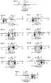
- Fig. 1a to 1j explain the principle underlying the invention closer.
- Fig. 2 shows a self-backup set in a schematic representation according to a first embodiment.
- Fig. 3 reproduces the depiction of a carbine and
- Fig. 4 illustrates its items. The function of this carbine is based on the Fig. 5a to 5d explained in more detail.
- Fig. 6a illustrates a key in side view and Fig. 6b in front view. Based on Fig. 7a to 7d the function of a modified embodiment of a carabiner is illustrated.
- the Fig. 8a to 8f illustrate the interaction of two carabiners by an electrical signal.
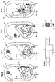
- a platform 1 of a high ropes course is shown, wherein a rope, such as a steel cable 2, from mast 3 to mast 3 is stretched.
- the steel cable 2 is attached to each mast 3, for example, with a wrapping 4, and serves as a securing point to protect against a crash of a person.
- a key 5 for securing or unlocking two carabiners K1 and K2 of a self-locking set, each of the carabiners K1 and K2 being connected to a securing person via a connecting piece 6.
- This connector 6 can, as in Fig.
- Fig. 1 is the respectively locked against opening carabiner K1 or K2 designated S and applied with black color. According to Fig. 1b the security person passes along the steel cable 2 to a platform 1 surrounding the mast 3, wherein the carabiner K2 is blocked from opening and the carabiner K1 is not blocked, but is still closed. Both carabiners K1 and K2 are hung on steel rope 2.
- Fig. 1c shows the opening of the carbine K1, which subsequently, as shown in Fig. 1d is shown in the steel cable 2, which continues from the mast 3 to another mast, is hung.
- Fig. 1e shows, the carabiner K1 locked by means of the key 5, whereby the carabiner K1 is secured against opening.
- both karabiners K1l and K2 are locked during the locking ( Fig. 1f ).
- the carabiner K2 is unlocked via the coupling means 7 and it can be the carabiner K2, as the Fig. 1h shows are opened and are also mounted on the mast 3 continuing steel rope 2 (see. Fig. 1i ).
- the security person from the platform 1 along the steel cable 2 can move on; she is completely secured against falling by the now locked carabiner K1.
- the security person is insecure or mistreated even for a moment during the transfer process unsecured.
- One of the carbines K1 or K2 is always secured against opening, i. blocked.
- Fig. 2 illustrates a mechanical coupling of the two carabiners K1 and K2 by means of a Bowden cable 7, which is loosely installed in the security band 6, so that in case of a fall of the security person or in the event of an otherwise caused tensile load on the security tape 6, only the backup tape 6, but not the Bowden cable 7 is loaded.
- the construction of a carbine K1 or K2 is off FIG. 3 and FIG. 4 seen.
- the snapper 8 of the carabiner is pivotally mounted via a pivot axis 9 on the carabiner body 10 as usual, wherein in the closed state, a locking of the free end of the snapper 8 on the carabiner body 10 is possible, for example by a notch 11 on the carabiner body 10 and into the notch
- the snapper 8 has a projection 13 extending to the carabiner body 10, which is coupled by means of a guide pin 14 to a blocking device 15, namely into a groove 16 or into a slot of the blocking device 15 engages along which groove 16 (or which slot) of this guide pin 14, depending on the position of the blocking device 15 is movable, which can open depending on the position of the blocking device 15 of the snapper 8 or blocked against opening.
- the slot 16 has two arcuate branches 16 'and 16 "which are at an angle to each other
- the carabiner body 10 is provided with a housing 17 which partially closes the space enclosed by the carabiner body 10 and which has an eyelet 18 for a securing band
- the locking device 15 is pivotally mounted to the housing 17 with an axle 20. Further, the housing 17 has a keyhole 19 in alignment with the branch 16 'or the groove 16.
- the blocking device 15 is further connected to the Bowden cable 7 via a fastening knob 21.
- the carabiner body 10 further comprises an adjusting device 22, for example a thread with locknut, in order to adjust the Bowden cable 7 to its correct length for the purpose of cooperating with a second carabiner of the same design.
- Fig. 3 still illustrates the carabiner running Steel rope 2.
- Fig. 5a is the carbine K1 in the closed state and the blocking device 15 prevents in the Fig. 5a shown opening the snapper 8, especially as a sliding of the guide pin 14 in the branch 16 "of the groove 16 is not possible alone by moving the snapper 8, the guide pin 14 is here in the branch 16 'of the groove 16.
- An opening of this carabiner would only be possible if the second carabiner K2, which belongs to this self - belay set, is in an unlocked state at that time, as in Fig. 5b is illustrated, is closed.
- Fig. 5b shows the carbine K1 in unlocked condition, with the snapper 8, as in Fig. 5c is shown by the guide pin 14 can slide along the branch 16 "of the groove 16, so that the carabiner K1 can be unhooked from the steel cable 2.
- Fig. 7a to 7d illustrates the function of a carabiner K1, which is also coupled by means of a Bowden cable 7 with a carabiner K2, but wherein the carabiner K1 has a variant of a blocking device 15 which is provided with a locking extension 24, which consists of a position blocking the snapper 8, as in Fig. 7a illustrated in a position releasing the snapper 8 to an opening movement position in Fig. 7b is pivoted by pivoting the blocking device 15, wherein the Bowden cable 7 again brings the carabiner K2 coupled to the carabiner K1 into an opening-enabling position or into a closed position by moving the blocking device 15 of the carabiner K2 against the movement of the blocking device 15 of the carabiner K1.
- a leaf spring B ensures a retention of the blocking device 15 in its end positions, which in the Fig. 7a, 7b and 7c are shown.
- Fig. 7d shows the use of the key 5 after hooking the carabiner in the rope, what in Fig. 7c is illustrated.
- a lock S designed as a toothed belt is provided, into which the fastening knob 21 engages with a counter-toothing. Only by a pulling movement of the Bowden cable 7, the tooth connection can be solved.
- electrically operated coupling means T could be provided for communication between the carabiners K1 and K2.
- Such variants require a power supply of the self-backup set.
- the advantage of such an electrical coupling of the carabiner K1 and K2 is that the connection between the carabiners K1 and K2 can be laid as a flexible multipolar cable T, whereby the connecting piece 6 is easier to handle and less sensitive.
- Fig. 8a to 8d In each case, two karabiners K1 and K2 of a self-locking set are illustrated, wherein the electrical coupling is illustrated by means of dotted lines.
- a battery 25 is provided, which is provided via a socket 26 which is provided in the housing 17 of the carabiner body 10, or via a switch 27 according to a in Fig. 8e variant shown, but otherwise with the variant Fig. 8a is identical to a double coil 28 - formed by the coils 28 'and 28 "- in which an iron core 29 is axially displaceable, this iron core 29 is connected via a push rod 30 to the blocking device 15, so that this blocking device 15 is displaced by displacement of the iron core 29 from an in Fig. 8a for the carabiner K1 open position shown in an in Fig. 8b for the carabiner K1 shown blocking position is movable.
- An extension 13 of the snapper 8 is similar to that in FIG. 3 and FIG. 4 illustrated embodiment with a guide pin 14 in a groove 16 and a slot of the blocking device 15 out.
- a contact point 31 for closing a switch 32 is provided at the blocking device 15.
- a plug 34 which shorts the socket 26, whereupon the piston 5 in the in Fig.
- Fig. 8f shows an embodiment according to which a power supply of the carabiners K1 and K2 via the key 5, which is connected to a central power supply point, eg wiring all keys in a high ropes course, or a decentralized power supply point, eg to a solar system or a battery or a battery connected.
- a central power supply point eg wiring all keys in a high ropes course
- a decentralized power supply point eg to a solar system or a battery or a battery connected.
- the Distilsset invention can be used not only for via ferrata and high ropes gardens, but also for walking exposed sites on buildings, such as skyscrapers, masts, bridges, etc., for example in repair and / or maintenance, and in ships and also in space.
- the fields of application for the self-locking set according to the invention are explained in more detail below:
- the fully secured self-backup set enables maximum subscriber security on high ropes courses. This allows the participant to focus fully on the exercises and less on their own safety.
- the fully secured self-backup kit offers the opportunity to climb larger groups, such as school classes, under relatively little supervision.
- the climber hangs himself at the beginning of the climb, uses the trail to the end and can only be unlocked there.
- Exterior work on buildings such as the maintenance of wind power plants, cleaning windows on skyscrapers or renovations, are often carried out scaffolding.
- the fully secured self-backup set makes it impossible to accidentally unlock it while working.
- the fully secure self-backup set can be used not only for climbing, but also for securing in completely different areas, up to securing astronauts outside a spaceship.
- the trainers are therefore required both in terms of safety and organization.
- the direction of the participants can be influenced by a specific arrangement of the keys for the continuously secured self-backup set.
- An exercise can only be entered on the side where a key is mounted.
Landscapes
- Engineering & Computer Science (AREA)
- Architecture (AREA)
- Health & Medical Sciences (AREA)
- Mechanical Engineering (AREA)
- General Health & Medical Sciences (AREA)
- Civil Engineering (AREA)
- Structural Engineering (AREA)
- General Engineering & Computer Science (AREA)
- Pulmonology (AREA)
- Physical Education & Sports Medicine (AREA)
- Business, Economics & Management (AREA)
- Emergency Management (AREA)
- Emergency Lowering Means (AREA)
- Refuge Islands, Traffic Blockers, Or Guard Fence (AREA)
Claims (15)
- Kit autobloquant comportant deux mousquetons (K1 et K2) pouvant être bloqués pour empêcher toute ouverture au moyen d'un dispositif de blocage (15, 17) et pouvant être suspendus à des emplacements de sécurité (2), lesquels mousquetons sont fixés au niveau respectivement d'une pièce de liaison (6) pouvant être reliée à une personne à sécuriser, sachant que les dispositifs de blocage (15, 17) des deux mousquetons (K1, K2) sont couplés au moyen d'un moyen d'accouplement (7, 7'), caractérisé en ce- qu'est prévu comme partie du kit autobloquant un moyen de sécurité (5) pour les mousquetons (K1, K2), sachant que le kit autobloquant est configuré de telle manière que le moyen de sécurité (5) bloque au moyen d'un dispositif de blocage (15, 17), un mousqueton empêchant toute ouverture lorsque ledit mousqueton (K1, K2) est suspendu à l'emplacement de sécurité (2) et lorsque le moyen de sécurité (5) est actionné, sachant que le dispositif de blocage (17, 25) du deuxième mousqueton (K2, K1) est actionné par l'intermédiaire du moyen d'accouplement (7, 7') de telle manière que le deuxième mousqueton (K2, K1) est débloqué aux fins de l'ouverture de sorte que systématiquement uniquement un des mousquetons (K1, K2) peut être ouvert,dans lequel le dispositif de blocage est fixé pivotant par un axe à une boîte du mousqueton.
- Kit autobloquant selon la revendication 1, caractérisé en ce que le moyen d'accouplement (7, 7') est réalisé de manière à avoir une action mécanique.
- Kit autobloquant selon la revendication 2, caractérisé en ce que le moyen d'accouplement (7, 7') est un câble Bowden.
- Kit autobloquant selon la revendication 1, caractérisé en ce que le moyen d'accouplement (7, 7') a une action électrique.
- Kit autobloquant selon la revendication 4, caractérisé en ce que le moyen d'accouplement présente un câble multipolaire flexible.
- Kit autobloquant selon la revendication 1, caractérisé en ce que le moyen d'accouplement (7, 7') a une action s'effectuant par réception radio.
- Kit autobloquant selon la revendication 1, caractérisé en ce que le moyen d'accouplement (7, 7') a une action hydraulique.
- Kit autobloquant selon l'une des revendications 1 à 7, caractérisé en ce que des moyens de sécurité à action mécanique (5, 23) sont prévus, de préférence comme une clé (5) fixée au niveau de l'emplacement de sécurité.
- Kit autobloquant selon l'une des revendications 1 à 7, caractérisé en ce que des moyens de sécurité à action électrique (5, 34) sont prévus.
- Kit autobloquant selon l'une des revendications 1 à 7, caractérisé en ce que des moyens de sécurité électroniques sont prévus, tels que des puces informatiques.
- Kit autobloquant selon l'une des revendications 1 à 7, caractérisé en ce que des moyens de sécurité à action magnétique ou inductive sont prévus.
- Kit autobloquant selon l'une des revendications 1 à 7, caractérisé en ce que des moyens de sécurité à action optique sont prévus.
- Installation comportant deux ou plusieurs emplacements de sécurité (2), caractérisée en ce que les emplacements de sécurité (2) sont équipés des moyens de sécurité (5) selon l'une des revendications 8 à 12, lesquels emplacements agissent ensemble avec un kit autobloquant selon l'une quelconque des revendications 1 à 7.
- Installation selon la revendication 13, caractérisée en ce que les emplacements de sécurité (2) sont réalisés sous la forme de cordes (2) fixées à des points fixes, d'étriers, d'échelles ou de mains courantes.
- Installation selon la revendication 13 ou 14, caractérisée en ce que des emplacements de sécurité (2) adjacents sont disposés à portée les uns des autres.
Applications Claiming Priority (2)
| Application Number | Priority Date | Filing Date | Title |
|---|---|---|---|
| AT0177106A AT504458B1 (de) | 2006-10-23 | 2006-10-23 | Selbstsicherungsset sowie anlage mit sicherungsstellen |
| EP07815148.7A EP2083926B2 (fr) | 2006-10-23 | 2007-10-15 | Kit autobloquant et systeme avec emplacements de securite |
Related Parent Applications (3)
| Application Number | Title | Priority Date | Filing Date |
|---|---|---|---|
| EP07815148.7 Division | 2007-10-15 | ||
| EP07815148.7A Division EP2083926B2 (fr) | 2006-10-23 | 2007-10-15 | Kit autobloquant et systeme avec emplacements de securite |
| EP07815148.7A Division-Into EP2083926B2 (fr) | 2006-10-23 | 2007-10-15 | Kit autobloquant et systeme avec emplacements de securite |
Publications (3)
| Publication Number | Publication Date |
|---|---|
| EP2397191A1 EP2397191A1 (fr) | 2011-12-21 |
| EP2397191B1 EP2397191B1 (fr) | 2013-04-17 |
| EP2397191B2 true EP2397191B2 (fr) | 2016-12-21 |
Family
ID=38896689
Family Applications (2)
| Application Number | Title | Priority Date | Filing Date |
|---|---|---|---|
| EP11181303.6A Not-in-force EP2397191B2 (fr) | 2006-10-23 | 2007-10-15 | Kit autobloquant et système avec emplacements de sécurité |
| EP07815148.7A Active EP2083926B2 (fr) | 2006-10-23 | 2007-10-15 | Kit autobloquant et systeme avec emplacements de securite |
Family Applications After (1)
| Application Number | Title | Priority Date | Filing Date |
|---|---|---|---|
| EP07815148.7A Active EP2083926B2 (fr) | 2006-10-23 | 2007-10-15 | Kit autobloquant et systeme avec emplacements de securite |
Country Status (7)
| Country | Link |
|---|---|
| US (1) | US9174072B2 (fr) |
| EP (2) | EP2397191B2 (fr) |
| AT (1) | AT504458B1 (fr) |
| CA (1) | CA2666330A1 (fr) |
| DE (1) | DE202007019516U1 (fr) |
| ES (2) | ES2421259T3 (fr) |
| WO (1) | WO2008049143A1 (fr) |
Families Citing this family (35)
| Publication number | Priority date | Publication date | Assignee | Title |
|---|---|---|---|---|
| EP2081652B1 (fr) * | 2006-10-27 | 2016-12-14 | Edelrid GmbH & Co. KG | Dispositif de sécurisation |
| BE1017967A4 (nl) | 2008-01-23 | 2010-02-02 | Aerialtech Sa | Verbetering meelopende valbeveiliging met flexibele ankerlijn. |
| AT506420B1 (de) * | 2008-02-06 | 2011-07-15 | Strasser Philipp Mag | Sicherungseinrichtung |
| DE102008033431B4 (de) * | 2008-07-16 | 2010-03-04 | Faszinatour Touristik - Training - Event Gmbh | Anschlagelement für eine Sicherungseinrichtung |
| EP2314355A1 (fr) | 2009-10-22 | 2011-04-27 | Ghislain van de Walle | Ensemble d'auto-relais avec deux connecteurs |
| IT1397742B1 (it) * | 2010-01-20 | 2013-01-24 | 4Geco S R L | Sistema di sicurezza a due moschettoni da agganciare ciascuno ad un elemento fisso di ancoraggio per impieghi alpinistici, parchi avventura, per lavori relativi a strutture civili o lavori in fune in genere |
| DE102010005910B4 (de) | 2010-01-27 | 2014-11-06 | Bornack Gmbh & Co. Kg | Verdrillschutzanordnung |
| FR2967076B1 (fr) * | 2010-11-08 | 2012-11-30 | Thierry Jean Alain Cornil Dehondt | Dispositif d'arrimage de securite et ensemble d'arrimage pourvu d'un tel dispositif |
| FR2972361B1 (fr) * | 2011-03-09 | 2013-07-05 | Soream | Mousqueton de securite |
| FR2972358B1 (fr) * | 2011-03-09 | 2013-04-26 | Soream | Longe de securite pour assurer une personne a une ligne de vie comportant des mousquetons en interaction les uns avec les autres. |
| US10434343B1 (en) * | 2011-03-14 | 2019-10-08 | Climb Tech, Llc | Quick-release attachment point for fall protection |
| DE102011017736B4 (de) | 2011-04-28 | 2013-10-31 | Bornack Gmbh & Co. Kg | Drehwirbelanordnung |
| EA021111B1 (ru) * | 2011-10-14 | 2015-04-30 | Михаил Михайлович ШАРОЙКО | Фиксирующее устройство |
| DE102012212192B4 (de) | 2012-07-12 | 2023-04-27 | Convexis Gmbh | Verfahren zum Betreiben eines Hochseilgartens und Hochseilgarten |
| WO2014009392A2 (fr) | 2012-07-12 | 2014-01-16 | Convexis Gmbh | Dispositif d'ancrage présentant des points d'ancrage parcourus par du courant (éléments antichute), procédé pour faire fonctionner un site d'accrobranche, élément de liaison à ordonnancement, identification et réception de données électroniques de points d'ancrage parcourus par du courant |
| FR2995216B1 (fr) | 2012-09-12 | 2015-05-01 | Soream | Longe de securite |
| GB2510096B (en) * | 2012-11-01 | 2015-08-26 | Skanska Uk Plc | Safety equipment |
| US20150246455A1 (en) * | 2013-06-27 | 2015-09-03 | ICOR Technology Inc. | Remote cutting tool |
| DE102014000019A1 (de) | 2013-07-31 | 2015-02-05 | Edelrid Gmbh & Co. Kg | Vorrichtung zur Sicherung von Personen insbesondere in Hochseilgärten |
| WO2015038509A1 (fr) * | 2013-09-10 | 2015-03-19 | ACCO Brands Corporation | Mousqueton comprenant un mécanisme de verrouillage |
| DE102015113329B4 (de) | 2014-08-14 | 2024-05-16 | Edelrid Gmbh & Co. Kg | Vorrichtung zur Sicherung von Personen insbesondere in Hochseilgärten mit zwei Karabinern |
| DE102014117329B4 (de) | 2014-11-26 | 2019-10-31 | Bornack Gmbh & Co. Kg | System zur Steuerung einer Nutzung einer Übung durch eine Person in einem Kletterpark |
| EP3115084B1 (fr) * | 2015-07-08 | 2019-12-11 | Safety Engineering Ltd. | Agencement de sécurité automatique pour des applications d'escalade |
| FR3063017B1 (fr) * | 2017-02-20 | 2021-07-16 | Thierry Dehondt | Systeme d'arrimage d'une personne en hauteur. |
| US11235185B1 (en) * | 2017-08-09 | 2022-02-01 | Buckingham Manufacturing Company, Inc. | Proximity lanyard system |
| WO2019157007A1 (fr) * | 2018-02-09 | 2019-08-15 | 3M Innovative Properties Company | Équipement de protection contre les chutes comprenant un capteur inductif pour l'état de connexion et la commande |
| CN108245803B (zh) * | 2018-03-14 | 2023-05-23 | 国网山东省电力公司阳谷县供电公司 | 一种爬梯防坠落安全防护工具 |
| US11433263B1 (en) * | 2018-06-14 | 2022-09-06 | Jerry Bishop | Structure climbing safety device |
| US20200094086A1 (en) * | 2018-09-20 | 2020-03-26 | Perfectvision Manufacturing, Inc. | Safety Cable Routing System |
| FR3109092A1 (fr) | 2020-04-14 | 2021-10-15 | Stéphane DENJEAN | Dispositif d’assurage à double mousquetons |
| US11453344B2 (en) * | 2020-04-22 | 2022-09-27 | Yeong Ton Industrial Co., Ltd. | Top tube adaptor |
| DE102021104988B3 (de) | 2021-03-02 | 2022-05-05 | Philipp Strasser | Selbstsicherungsvorrichtung mit verunmöglichtem Verbleib eines Kommunikationsmittels in einer undefinierten Zwischenstellung |
| US12366258B2 (en) | 2021-04-23 | 2025-07-22 | TruBlue, LLC | Connector apparatuses |
| CN114082118B (zh) * | 2021-11-24 | 2022-11-29 | 国网山东省电力公司阳谷县供电公司 | 一种高空防坠工具及使用方法 |
| DE102022103963A1 (de) | 2022-02-20 | 2023-08-24 | Edelrid Gmbh & Co. Kg | Klettersteigkarabiner |
Family Cites Families (20)
| Publication number | Priority date | Publication date | Assignee | Title |
|---|---|---|---|---|
| DE7919515U1 (de) | 1979-10-04 | Mittelmann & Co Armaturenwerk, 5603 Wuelfrath | Sicherungshaken für absturzgefährdete Personen oder Sachen | |
| US2116880A (en) | 1935-08-27 | 1938-05-10 | Harold D Dee | Self locking cable hook |
| US3493260A (en) * | 1968-06-14 | 1970-02-03 | Eastern Rotorcraft Corp | Safety hook |
| DE1812115A1 (de) * | 1968-12-02 | 1970-06-18 | Sigmatex Ag | Halterung fuer die Gurtschlaufe eines Dreipunktsicherheitsgurtes von Kraftfahrzeugen |
| FR2483791A1 (fr) | 1980-06-04 | 1981-12-11 | Kaminski Jean Claude | Perfectionnements aux mousquetons pour la pratique de la varappe et autres applications analogues |
| FR2483781A1 (fr) | 1980-06-10 | 1981-12-11 | Charbonnages De France | Procede d'epuration d'effluents gazeux malodorants |
| US4423795A (en) * | 1982-02-19 | 1984-01-03 | General Motors Corporation | Wheeled vehicle with cambering front module |
| US4528728A (en) | 1982-10-13 | 1985-07-16 | Rose Manufacturing Company | Locking snap hook |
| US4423796A (en) * | 1982-11-23 | 1984-01-03 | Sulowski Andrew C | Ladder climber's safety device |
| FR2588477B1 (fr) * | 1985-10-11 | 1988-01-29 | Ecole Nale Superi Creation Ind | Dispositif de sauvetage a declenchement automatique |
| CA2189095C (fr) * | 1996-10-29 | 2004-10-19 | Gilles Roy | Dispositif de retenue pour l'entretien des pylones d'antennes |
| US5927431A (en) * | 1997-01-31 | 1999-07-27 | Klein, Jr.; Richard T. | Guarded snap hook |
| AU6166699A (en) * | 1998-09-30 | 2000-04-17 | Paul D. Baillargeon | Fall protection system and method |
| US6648101B2 (en) * | 2001-05-24 | 2003-11-18 | Michael P. Kurtgis | Fall protection lanyard apparatus |
| DE10328346A1 (de) | 2003-06-24 | 2005-01-13 | Land- und Forstwirtschaftliche Betriebe Klöber GmbH | Karabinerhaken |
| DE102005009946B3 (de) | 2005-03-04 | 2006-07-06 | Michael Halfer | Absturzsicherung für Personen |
| DE102006010898A1 (de) * | 2006-03-09 | 2007-09-13 | Faszinatour Touristik - Training - Event Gmbh | Sicherungseinrichtung und Kletteranlage |
| AT506420B1 (de) * | 2008-02-06 | 2011-07-15 | Strasser Philipp Mag | Sicherungseinrichtung |
| FR2967076B1 (fr) * | 2010-11-08 | 2012-11-30 | Thierry Jean Alain Cornil Dehondt | Dispositif d'arrimage de securite et ensemble d'arrimage pourvu d'un tel dispositif |
| US9168421B2 (en) * | 2011-02-15 | 2015-10-27 | Honeywell International Inc. | Fall protection device for use in climbing poles |
-
2006
- 2006-10-23 AT AT0177106A patent/AT504458B1/de not_active IP Right Cessation
-
2007
- 2007-10-15 WO PCT/AT2007/000481 patent/WO2008049143A1/fr not_active Ceased
- 2007-10-15 US US12/311,858 patent/US9174072B2/en active Active
- 2007-10-15 ES ES11181303T patent/ES2421259T3/es active Active
- 2007-10-15 EP EP11181303.6A patent/EP2397191B2/fr not_active Not-in-force
- 2007-10-15 DE DE202007019516U patent/DE202007019516U1/de not_active Expired - Lifetime
- 2007-10-15 CA CA002666330A patent/CA2666330A1/fr not_active Abandoned
- 2007-10-15 ES ES07815148T patent/ES2402785T3/es active Active
- 2007-10-15 EP EP07815148.7A patent/EP2083926B2/fr active Active
Also Published As
| Publication number | Publication date |
|---|---|
| EP2397191B1 (fr) | 2013-04-17 |
| EP2083926A1 (fr) | 2009-08-05 |
| WO2008049143A1 (fr) | 2008-05-02 |
| ES2402785T3 (es) | 2013-05-08 |
| AT504458B1 (de) | 2010-02-15 |
| EP2397191A1 (fr) | 2011-12-21 |
| DE202007019516U1 (de) | 2013-03-18 |
| ES2421259T3 (es) | 2013-08-30 |
| US9174072B2 (en) | 2015-11-03 |
| EP2083926B1 (fr) | 2013-01-16 |
| AT504458A1 (de) | 2008-05-15 |
| US20110031065A1 (en) | 2011-02-10 |
| EP2083926B2 (fr) | 2017-11-08 |
| CA2666330A1 (fr) | 2008-05-02 |
| DE202007019516U8 (de) | 2014-11-06 |
Similar Documents
| Publication | Publication Date | Title |
|---|---|---|
| EP2397191B2 (fr) | Kit autobloquant et système avec emplacements de sécurité | |
| EP2240664B1 (fr) | Dispositif de securite | |
| DE60222239T2 (de) | Bewegliches absturzsicherungsgerät für rettungsseil | |
| DE69611064T2 (de) | Bewegliches Absturzsicherungsgerät für flexibles Rettungsseil | |
| EP1832315B1 (fr) | Dispositif de sécurité et l'installation d'escalade | |
| EP2590716B1 (fr) | Dispositif et procédé de sécurisation d'ascension | |
| DE3844258C2 (fr) | ||
| WO2009092576A1 (fr) | Procédé et dispositif de protection anti-chute | |
| EP3223918B1 (fr) | Système de commande permettant à une personne d'utiliser une attraction dans un parc d'escalade | |
| WO2014009392A2 (fr) | Dispositif d'ancrage présentant des points d'ancrage parcourus par du courant (éléments antichute), procédé pour faire fonctionner un site d'accrobranche, élément de liaison à ordonnancement, identification et réception de données électroniques de points d'ancrage parcourus par du courant | |
| DE3728282A1 (de) | Absturzsicherungsvorrichtung, insbesondere fuer dacharbeiten | |
| EP0678639A1 (fr) | Dispositif de verrouillage pour volets, portes et éléments similaires mobiles sur un rail fixe | |
| DE102012212192B4 (de) | Verfahren zum Betreiben eines Hochseilgartens und Hochseilgarten | |
| DE8706660U1 (de) | Kletterkarabiener fernbedienbar | |
| WO2011092018A1 (fr) | Émerillon à protection antitorsion | |
| EP0747284B1 (fr) | Dispositif antivol pour un objet mobile, en particulier une bicyclette | |
| DE102007015313B4 (de) | Vorrichtung zum plötzlichen Abwerfen von Vorhängen und sonstigen Dekorationen in der Bühnen- und Veranstaltungstechnik | |
| DE29922278U1 (de) | Absturzsicherung für Gittermaste und ähnliche Bauwerke | |
| DE202017101379U1 (de) | Sicherungsvorrichtung für eine Person | |
| DE29520400U1 (de) | Vorrichtung zum Versetzen einer Steigschutz-Fangeinrichtung von einem ersten Steigweg zu einem zweiten Steigweg | |
| DE20121664U1 (de) | Hochziehbare Kletterwand | |
| DE2950820A1 (de) | Schiebeleiter | |
| DE102011017736A1 (de) | Drehwirbelanordnung | |
| DE3931357A1 (de) | Leiter | |
| DE20309393U1 (de) | Spiel- oder Sportwand, insbesondere Kletterwand |
Legal Events
| Date | Code | Title | Description |
|---|---|---|---|
| AC | Divisional application: reference to earlier application |
Ref document number: 2083926 Country of ref document: EP Kind code of ref document: P |
|
| AK | Designated contracting states |
Kind code of ref document: A1 Designated state(s): AT BE BG CH CY CZ DE DK EE ES FI FR GB GR HU IE IS IT LI LT LU LV MC MT NL PL PT RO SE SI SK TR |
|
| PUAI | Public reference made under article 153(3) epc to a published international application that has entered the european phase |
Free format text: ORIGINAL CODE: 0009012 |
|
| 17P | Request for examination filed |
Effective date: 20120620 |
|
| GRAP | Despatch of communication of intention to grant a patent |
Free format text: ORIGINAL CODE: EPIDOSNIGR1 |
|
| GRAS | Grant fee paid |
Free format text: ORIGINAL CODE: EPIDOSNIGR3 |
|
| GRAA | (expected) grant |
Free format text: ORIGINAL CODE: 0009210 |
|
| AC | Divisional application: reference to earlier application |
Ref document number: 2083926 Country of ref document: EP Kind code of ref document: P |
|
| AK | Designated contracting states |
Kind code of ref document: B1 Designated state(s): AT BE BG CH CY CZ DE DK EE ES FI FR GB GR HU IE IS IT LI LT LU LV MC MT NL PL PT RO SE SI SK TR |
|
| REG | Reference to a national code |
Ref country code: GB Ref legal event code: FG4D Free format text: NOT ENGLISH |
|
| REG | Reference to a national code |
Ref country code: CH Ref legal event code: EP |
|
| REG | Reference to a national code |
Ref country code: IE Ref legal event code: FG4D Free format text: LANGUAGE OF EP DOCUMENT: GERMAN |
|
| REG | Reference to a national code |
Ref country code: AT Ref legal event code: REF Ref document number: 606872 Country of ref document: AT Kind code of ref document: T Effective date: 20130515 |
|
| REG | Reference to a national code |
Ref country code: DE Ref legal event code: R096 Ref document number: 502007011641 Country of ref document: DE Effective date: 20130613 |
|
| REG | Reference to a national code |
Ref country code: LT Ref legal event code: MG4D |
|
| REG | Reference to a national code |
Ref country code: NL Ref legal event code: VDEP Effective date: 20130417 |
|
| PG25 | Lapsed in a contracting state [announced via postgrant information from national office to epo] |
Ref country code: IS Free format text: LAPSE BECAUSE OF FAILURE TO SUBMIT A TRANSLATION OF THE DESCRIPTION OR TO PAY THE FEE WITHIN THE PRESCRIBED TIME-LIMIT Effective date: 20130817 Ref country code: SI Free format text: LAPSE BECAUSE OF FAILURE TO SUBMIT A TRANSLATION OF THE DESCRIPTION OR TO PAY THE FEE WITHIN THE PRESCRIBED TIME-LIMIT Effective date: 20130417 Ref country code: SE Free format text: LAPSE BECAUSE OF FAILURE TO SUBMIT A TRANSLATION OF THE DESCRIPTION OR TO PAY THE FEE WITHIN THE PRESCRIBED TIME-LIMIT Effective date: 20130417 Ref country code: PT Free format text: LAPSE BECAUSE OF FAILURE TO SUBMIT A TRANSLATION OF THE DESCRIPTION OR TO PAY THE FEE WITHIN THE PRESCRIBED TIME-LIMIT Effective date: 20130819 Ref country code: FI Free format text: LAPSE BECAUSE OF FAILURE TO SUBMIT A TRANSLATION OF THE DESCRIPTION OR TO PAY THE FEE WITHIN THE PRESCRIBED TIME-LIMIT Effective date: 20130417 Ref country code: GR Free format text: LAPSE BECAUSE OF FAILURE TO SUBMIT A TRANSLATION OF THE DESCRIPTION OR TO PAY THE FEE WITHIN THE PRESCRIBED TIME-LIMIT Effective date: 20130718 Ref country code: LT Free format text: LAPSE BECAUSE OF FAILURE TO SUBMIT A TRANSLATION OF THE DESCRIPTION OR TO PAY THE FEE WITHIN THE PRESCRIBED TIME-LIMIT Effective date: 20130417 |
|
| PLBI | Opposition filed |
Free format text: ORIGINAL CODE: 0009260 |
|
| PG25 | Lapsed in a contracting state [announced via postgrant information from national office to epo] |
Ref country code: LV Free format text: LAPSE BECAUSE OF FAILURE TO SUBMIT A TRANSLATION OF THE DESCRIPTION OR TO PAY THE FEE WITHIN THE PRESCRIBED TIME-LIMIT Effective date: 20130417 Ref country code: CY Free format text: LAPSE BECAUSE OF FAILURE TO SUBMIT A TRANSLATION OF THE DESCRIPTION OR TO PAY THE FEE WITHIN THE PRESCRIBED TIME-LIMIT Effective date: 20130417 Ref country code: PL Free format text: LAPSE BECAUSE OF FAILURE TO SUBMIT A TRANSLATION OF THE DESCRIPTION OR TO PAY THE FEE WITHIN THE PRESCRIBED TIME-LIMIT Effective date: 20130417 Ref country code: BG Free format text: LAPSE BECAUSE OF FAILURE TO SUBMIT A TRANSLATION OF THE DESCRIPTION OR TO PAY THE FEE WITHIN THE PRESCRIBED TIME-LIMIT Effective date: 20130717 |
|
| 26 | Opposition filed |
Opponent name: SARL DEHONDT Effective date: 20131031 |
|
| PLBI | Opposition filed |
Free format text: ORIGINAL CODE: 0009260 |
|
| REG | Reference to a national code |
Ref country code: DE Ref legal event code: R026 Ref document number: 502007011641 Country of ref document: DE Effective date: 20131031 |
|
| PG25 | Lapsed in a contracting state [announced via postgrant information from national office to epo] |
Ref country code: EE Free format text: LAPSE BECAUSE OF FAILURE TO SUBMIT A TRANSLATION OF THE DESCRIPTION OR TO PAY THE FEE WITHIN THE PRESCRIBED TIME-LIMIT Effective date: 20130417 Ref country code: CZ Free format text: LAPSE BECAUSE OF FAILURE TO SUBMIT A TRANSLATION OF THE DESCRIPTION OR TO PAY THE FEE WITHIN THE PRESCRIBED TIME-LIMIT Effective date: 20130417 Ref country code: SK Free format text: LAPSE BECAUSE OF FAILURE TO SUBMIT A TRANSLATION OF THE DESCRIPTION OR TO PAY THE FEE WITHIN THE PRESCRIBED TIME-LIMIT Effective date: 20130417 Ref country code: DK Free format text: LAPSE BECAUSE OF FAILURE TO SUBMIT A TRANSLATION OF THE DESCRIPTION OR TO PAY THE FEE WITHIN THE PRESCRIBED TIME-LIMIT Effective date: 20130417 |
|
| PGFP | Annual fee paid to national office [announced via postgrant information from national office to epo] |
Ref country code: AT Payment date: 20131029 Year of fee payment: 7 |
|
| 26 | Opposition filed |
Opponent name: CONSTRUCTION VAN DE WALLE Effective date: 20140115 |
|
| PLAX | Notice of opposition and request to file observation + time limit sent |
Free format text: ORIGINAL CODE: EPIDOSNOBS2 |
|
| PG25 | Lapsed in a contracting state [announced via postgrant information from national office to epo] |
Ref country code: RO Free format text: LAPSE BECAUSE OF FAILURE TO SUBMIT A TRANSLATION OF THE DESCRIPTION OR TO PAY THE FEE WITHIN THE PRESCRIBED TIME-LIMIT Effective date: 20130417 Ref country code: NL Free format text: LAPSE BECAUSE OF FAILURE TO SUBMIT A TRANSLATION OF THE DESCRIPTION OR TO PAY THE FEE WITHIN THE PRESCRIBED TIME-LIMIT Effective date: 20130417 |
|
| PGFP | Annual fee paid to national office [announced via postgrant information from national office to epo] |
Ref country code: ES Payment date: 20131014 Year of fee payment: 7 Ref country code: IT Payment date: 20131016 Year of fee payment: 7 |
|
| PLBB | Reply of patent proprietor to notice(s) of opposition received |
Free format text: ORIGINAL CODE: EPIDOSNOBS3 |
|
| BERE | Be: lapsed |
Owner name: STRASSER, PHILIPP Effective date: 20131031 |
|
| PG25 | Lapsed in a contracting state [announced via postgrant information from national office to epo] |
Ref country code: MC Free format text: LAPSE BECAUSE OF FAILURE TO SUBMIT A TRANSLATION OF THE DESCRIPTION OR TO PAY THE FEE WITHIN THE PRESCRIBED TIME-LIMIT Effective date: 20130417 |
|
| REG | Reference to a national code |
Ref country code: CH Ref legal event code: PL |
|
| REG | Reference to a national code |
Ref country code: IE Ref legal event code: MM4A |
|
| PG25 | Lapsed in a contracting state [announced via postgrant information from national office to epo] |
Ref country code: CH Free format text: LAPSE BECAUSE OF NON-PAYMENT OF DUE FEES Effective date: 20131031 Ref country code: LI Free format text: LAPSE BECAUSE OF NON-PAYMENT OF DUE FEES Effective date: 20131031 |
|
| PG25 | Lapsed in a contracting state [announced via postgrant information from national office to epo] |
Ref country code: BE Free format text: LAPSE BECAUSE OF NON-PAYMENT OF DUE FEES Effective date: 20131031 |
|
| PG25 | Lapsed in a contracting state [announced via postgrant information from national office to epo] |
Ref country code: IE Free format text: LAPSE BECAUSE OF NON-PAYMENT OF DUE FEES Effective date: 20131015 |
|
| REG | Reference to a national code |
Ref country code: AT Ref legal event code: MM01 Ref document number: 606872 Country of ref document: AT Kind code of ref document: T Effective date: 20141015 |
|
| PG25 | Lapsed in a contracting state [announced via postgrant information from national office to epo] |
Ref country code: TR Free format text: LAPSE BECAUSE OF FAILURE TO SUBMIT A TRANSLATION OF THE DESCRIPTION OR TO PAY THE FEE WITHIN THE PRESCRIBED TIME-LIMIT Effective date: 20130417 |
|
| PG25 | Lapsed in a contracting state [announced via postgrant information from national office to epo] |
Ref country code: LU Free format text: LAPSE BECAUSE OF NON-PAYMENT OF DUE FEES Effective date: 20131015 Ref country code: HU Free format text: LAPSE BECAUSE OF FAILURE TO SUBMIT A TRANSLATION OF THE DESCRIPTION OR TO PAY THE FEE WITHIN THE PRESCRIBED TIME-LIMIT; INVALID AB INITIO Effective date: 20071015 |
|
| PLAY | Examination report in opposition despatched + time limit |
Free format text: ORIGINAL CODE: EPIDOSNORE2 |
|
| PG25 | Lapsed in a contracting state [announced via postgrant information from national office to epo] |
Ref country code: MT Free format text: LAPSE BECAUSE OF FAILURE TO SUBMIT A TRANSLATION OF THE DESCRIPTION OR TO PAY THE FEE WITHIN THE PRESCRIBED TIME-LIMIT Effective date: 20130417 Ref country code: IT Free format text: LAPSE BECAUSE OF NON-PAYMENT OF DUE FEES Effective date: 20141015 Ref country code: AT Free format text: LAPSE BECAUSE OF NON-PAYMENT OF DUE FEES Effective date: 20141015 |
|
| REG | Reference to a national code |
Ref country code: FR Ref legal event code: PLFP Year of fee payment: 9 |
|
| PLBC | Reply to examination report in opposition received |
Free format text: ORIGINAL CODE: EPIDOSNORE3 |
|
| PG25 | Lapsed in a contracting state [announced via postgrant information from national office to epo] |
Ref country code: ES Free format text: LAPSE BECAUSE OF NON-PAYMENT OF DUE FEES Effective date: 20141016 |
|
| REG | Reference to a national code |
Ref country code: FR Ref legal event code: PLFP Year of fee payment: 10 |
|
| PUAH | Patent maintained in amended form |
Free format text: ORIGINAL CODE: 0009272 |
|
| STAA | Information on the status of an ep patent application or granted ep patent |
Free format text: STATUS: PATENT MAINTAINED AS AMENDED |
|
| 27A | Patent maintained in amended form |
Effective date: 20161221 |
|
| AK | Designated contracting states |
Kind code of ref document: B2 Designated state(s): AT BE BG CH CY CZ DE DK EE ES FI FR GB GR HU IE IS IT LI LT LU LV MC MT NL PL PT RO SE SI SK TR |
|
| REG | Reference to a national code |
Ref country code: DE Ref legal event code: R102 Ref document number: 502007011641 Country of ref document: DE |
|
| PG25 | Lapsed in a contracting state [announced via postgrant information from national office to epo] |
Ref country code: LV Free format text: LAPSE BECAUSE OF FAILURE TO SUBMIT A TRANSLATION OF THE DESCRIPTION OR TO PAY THE FEE WITHIN THE PRESCRIBED TIME-LIMIT Effective date: 20161221 |
|
| REG | Reference to a national code |
Ref country code: FR Ref legal event code: PLFP Year of fee payment: 11 |
|
| REG | Reference to a national code |
Ref country code: FR Ref legal event code: PLFP Year of fee payment: 12 |
|
| PGFP | Annual fee paid to national office [announced via postgrant information from national office to epo] |
Ref country code: GB Payment date: 20180920 Year of fee payment: 12 |
|
| PGFP | Annual fee paid to national office [announced via postgrant information from national office to epo] |
Ref country code: DE Payment date: 20180914 Year of fee payment: 12 |
|
| PGFP | Annual fee paid to national office [announced via postgrant information from national office to epo] |
Ref country code: FR Payment date: 20181025 Year of fee payment: 12 |
|
| REG | Reference to a national code |
Ref country code: DE Ref legal event code: R119 Ref document number: 502007011641 Country of ref document: DE |
|
| PG25 | Lapsed in a contracting state [announced via postgrant information from national office to epo] |
Ref country code: DE Free format text: LAPSE BECAUSE OF NON-PAYMENT OF DUE FEES Effective date: 20200501 |
|
| GBPC | Gb: european patent ceased through non-payment of renewal fee |
Effective date: 20191015 |
|
| PG25 | Lapsed in a contracting state [announced via postgrant information from national office to epo] |
Ref country code: FR Free format text: LAPSE BECAUSE OF NON-PAYMENT OF DUE FEES Effective date: 20191031 Ref country code: GB Free format text: LAPSE BECAUSE OF NON-PAYMENT OF DUE FEES Effective date: 20191015 |