EP2394846A1 - Sitzstruktur - Google Patents
Sitzstruktur Download PDFInfo
- Publication number
- EP2394846A1 EP2394846A1 EP11177011A EP11177011A EP2394846A1 EP 2394846 A1 EP2394846 A1 EP 2394846A1 EP 11177011 A EP11177011 A EP 11177011A EP 11177011 A EP11177011 A EP 11177011A EP 2394846 A1 EP2394846 A1 EP 2394846A1
- Authority
- EP
- European Patent Office
- Prior art keywords
- support structure
- seat frame
- seat
- connecting ends
- hook
- Prior art date
- Legal status (The legal status is an assumption and is not a legal conclusion. Google has not performed a legal analysis and makes no representation as to the accuracy of the status listed.)
- Granted
Links
- 238000000034 method Methods 0.000 claims description 11
- 238000004904 shortening Methods 0.000 claims description 3
- 239000000463 material Substances 0.000 description 11
- 238000010276 construction Methods 0.000 description 9
- 238000004519 manufacturing process Methods 0.000 description 8
- 238000009434 installation Methods 0.000 description 7
- 238000011068 loading method Methods 0.000 description 6
- 230000000717 retained effect Effects 0.000 description 6
- 239000002184 metal Substances 0.000 description 5
- 230000000694 effects Effects 0.000 description 3
- 230000015572 biosynthetic process Effects 0.000 description 2
- 230000006378 damage Effects 0.000 description 2
- 238000007493 shaping process Methods 0.000 description 2
- 230000000087 stabilizing effect Effects 0.000 description 2
- 238000003466 welding Methods 0.000 description 2
- 230000006978 adaptation Effects 0.000 description 1
- 239000011248 coating agent Substances 0.000 description 1
- 238000000576 coating method Methods 0.000 description 1
- 230000005923 long-lasting effect Effects 0.000 description 1
- 239000012858 resilient material Substances 0.000 description 1
- 230000003313 weakening effect Effects 0.000 description 1
- 238000004804 winding Methods 0.000 description 1
Images


Classifications
-
- B—PERFORMING OPERATIONS; TRANSPORTING
- B60—VEHICLES IN GENERAL
- B60N—SEATS SPECIALLY ADAPTED FOR VEHICLES; VEHICLE PASSENGER ACCOMMODATION NOT OTHERWISE PROVIDED FOR
- B60N2/00—Seats specially adapted for vehicles; Arrangement or mounting of seats in vehicles
- B60N2/70—Upholstery springs ; Upholstery
- B60N2/72—Attachment or adjustment thereof
-
- B—PERFORMING OPERATIONS; TRANSPORTING
- B60—VEHICLES IN GENERAL
- B60N—SEATS SPECIALLY ADAPTED FOR VEHICLES; VEHICLE PASSENGER ACCOMMODATION NOT OTHERWISE PROVIDED FOR
- B60N2/00—Seats specially adapted for vehicles; Arrangement or mounting of seats in vehicles
- B60N2/70—Upholstery springs ; Upholstery
- B60N2/7023—Coach-like constructions
- B60N2/7035—Cushions
- B60N2/7047—Springs
- B60N2/7058—Metallic springs
Definitions
- the present invention relates to a seat structure for supporting a seat cushioning, in particular for seats of motor vehicles.
- This seat structure preferably provides a seat frame and a support structure which is afterwards covered by a seat cushioning and a seat cover.
- Seat structures form the inner supporting structure of seats of all kinds. In seats of motor vehicles, this inner structure is formed by a support structure and a seat frame. At this construction consisting of seat frame and support structure, the cushioning and, if necessary, also a cover of the seat is mounted.
- this seat structure consists of a seat frame and a support structure.
- the support structure only serves for supporting the cushioning.
- support structures are known which can be used at the same time as an arching mechanic.
- Such an arching mechanic serves for the adaptation of the support structure to the curvature of the back of a seated person.
- This arching mechanic can be manually as well as motively adjusted and, thus, adapted. Therefore, such a support structure used as an arching mechanic enhances the comfort of the known vehicle seats of simple construction. It is furthermore known to combine said support structure with massage components which also increase the comfort of the seat.
- a seat structure also comprising a seat frame and a support structure.
- This seat structure consists of at least two lateral wire elements connected via a plurality of transversely extending wire elements.
- a plurality of springs is used. These springs are respectively hung up in the same number in the lateral wire elements and in the adjacent portions of the seat frame. Since every spring has to be individually connected to the support structure and the seat frame, this installation is time-consuming and, thus, expensive.
- a further seat structure is known from the EP-A-0 874 575 .
- this seat structure comprises a seat frame in which a support structure is mounted.
- the seat frame is made of four-cornered hollow sections since such profiles provide sufficient stability for the whole seat structure.
- the support structure is mounted also comprised of lateral wire elements and a plurality of transverse wires. A certain number of transverse wires extends beyond the lateral wire elements to terminate there in hook-like shaped ends. In this case, the hooks are oriented in such a way that they can be hooked in the hollow section of the seat frame arranged in parallel to the plane of the support structure. To this end, holes are arranged in this side of the hollow section of the seat frame.
- Such a seat structure in particular for motor vehicle seats, comprises a support structure having at least two lateral wire elements between which a plurality of transverse wires extends wherein at least two of said transverse wires extend beyond said lateral wire elements by means of connecting ends, and a seat frame at least partly surrounding said support structure wherein mounting means are rigidly arranged at the side of the seat frame directed to the support structure wherein said mounting means mount said support structure within said seat frame via a direct connection with said connecting end.
- a grid-like support structure is used.
- This support structure consists of at least two lateral wire elements and of transverse wires extending transversely thereto. These transverse wires extend on the one hand linearly or they comprise a curvilinear or a zigzag shape within the plane of the support structure. By this non-linear run, a springing or a complying of the support structure is enabled during loading and installation of said support structure. A certain number of transverse wires extends beyond the lateral wire elements in order to terminate in the connecting ends preferred according to the invention. These connecting ends comprise preferably according to the invention different shapes as descried below.
- the seat structure according to the invention comprises a seat frame surrounding said support structure.
- the seat frame provides a stabilizing inner structure of the whole seat which withstands the strong loadings generated by a seated person as well as the loadings in case of an accident in the motor vehicle.
- shaped or profiled seat frames are used.
- mounting means are provided at the side of the seat frame directed to the support structure.
- These mounting means are preferably according to the invention on the one hand worked from the seat frame, that means they form an integral component of these seat frames. In this manner, the efforts of production for this seat frame and, thus, for the whole seat structure are minimized.
- the mounting means are installed as additional elements at the side of the seat structure directed to the support structure, as for example by spot welding, riveting or the same.
- the connecting ends are preferably according to the invention directly mounted on the mounting means of the seat frame. That means that no intermediate springs or the same are used to provide the connection.
- the mounting means are integrally formed in the seat frame and/or they comprise a notch structure in which the connecting ends are received or latched.
- the connecting ends comprise a hook structure the hook plane of which is substantially perpendicularly aligned to the adjacent lateral wire element.
- the mounting means preferably according to the invention comprise loops in which the hook structure is hooked.
- the connecting ends of the support structure are formed as hook structures and the mounting means of the seat frame are formed as loops.
- the mounting means or loops comprise a notch structure.
- This notch structure is preferably according to the invention resiliently formed and dimensioned in such a way that the hook structure is received in this notch structure or it is even latched therein as soon as the hook structure is hung up in the loop.
- the loops comprise a profile to support the own stability and the stability of the seat frame.
- the loops in the side of the seat frame directed to the support structure are subjected to high tensile loads which are applied by the seated person via the hooked up support structure.
- the loops are preferably according to the invention shaped with profile. Such a shaped loop can only be bent or reshaped with high mechanical loads compared to a non-profiled loop.
- this profiling supports preferably according to the invention the stability of the seat frame.
- the loops are substantially arranged within the plane of the side of the seat frame directed to the support structure or they extend beyond this plane in the direction of the support structure.
- the loops are preferably according to the invention arranged in a common plane with the related side of the seat frame.
- connecting ends of low extent preferably according to the invention mounted in the seat frame.
- the loops preferably according to the invention extend beyond the plane of the side of the seat frame directed to the support structure, thereby the installation of the support structure within the seat frame is supported.
- the connecting ends comprise a loop structure or a hook structure the plane of which is substantially perpendicularly arranged relative to the adjacent lateral wire element.
- the mounting means comprise hook-like projections in which the loop structure or the hook structure is hooked in.
- the connecting ends of the support structure are formed as closed loop structures. Since these loop structures cannot be hooked in a further loop, the mounting means in the seat frame are preferably according to the invention formed as hook-like projections. These hook-like projections are formed by simply profiled webs having a sufficient size to hook in the connecting ends. It is furthermore preferred according to the invention that the seat frame comprises hook-like projections aligned in opposed directions but being substantially in parallel to the adjacent lateral wire element. Based on the opposed orientation of the projections, the loop structures cannot be simultaneously hooked out for example in case of a mechanical overload in the direction of the lateral wire element.
- the projections comprise a profile to support the own stability.
- the shaping of the loops and the projections serves for the increasing of stability.
- they can withstand higher mechanical loads in this manner and, thus, secure a high working life of the seat structure.
- the projections are substantially arranged within the plane of the side of the seat frame directed to the support structure or they extend beyond this plane in the direction of the support structure.
- the connecting ends comprise expanded ends or that the ends do not run in the direction of the connecting ends in order to mount the support structure.
- the support structure comprises a counter element mounted on the connecting end.
- the connecting ends are insertable in slit-shaped openings in the seat frame having the same or different orientations wherein the slit-shaped openings are open at one end or they are closed at both ends and they preferably comprise a keyhole-shape.
- the mounting means are slit-like configured in the inner side of the seat frame.
- This shape of the mounting means enables a mounting of the support structure with low efforts wherein at the same time the support structure is reliably retained.
- the mounting is effected by the preferred configuration according to the present invention of the ends of the connecting ends.
- the ends increase in thickness or they expand or they run in a different direction compared to the connecting ends.
- each shape of the ends of the respective connecting ends is preferred according to the invention which prevents a release of the support structure from the slit-like opening.
- the mounting means is a loop element mountable in the seat frame.
- the present invention further comprises a method for mounting a support structure in a seat frame of a seat of a vehicle, comprising the following steps: Expanding the support structure in a direction substantially parallel to the lateral connecting ends against an inner spring force of the support structure; mounting of the connecting ends on at least one mounting means by displacing the support structure in the plane surrounded by the seat frame wherein the mounting means is rigidly arranged at one side of the seat frame directed to the support structure; and shortening of the support structure based on the inner spring force substantially parallel to the direction of the lateral connecting ends so that the support structure is retained by itself in the seat frame.
- the support structure according to the invention is installed by an efficient three-step-method while known methods comprise at least four steps.
- the method according to the invention comprises first an elongating or stressing of the support structure in lateral direction. Afterwards, a displacing of the elongated support structure into the plane of the seat frame takes place whereby the connecting ends are connected to the mounting means. Finally, the support structure is relieved so that it fixes itself in the seat frame. In opposite thereto, a further displacing of the support structure is necessary in the prior art within the plane surrounded by the seat frame in order to hook in each other the mounting means and the connecting ends based on their orientation.
- the connecting ends comprise a hook structure the hook plane of which is essentially perpendicular to an adjacent lateral wire element wherein said hook structure is hooked in a releasably mounted loop structure or in a permanently mounted loop forming said mounting means.
- the connecting ends comprise expanded ends or the ends do not run in the direction of the connecting ends wherein the ends are hooked in slit-like openings forming the mounting means.
- the connecting ends comprise a counter element to retain the support structure at the seat frame between the expanded end and the counter element.
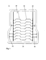
- the seat structure 1 which is shown according to a preferred embodiment of the present invention in Figure 1 , forms an inner structure of a seat, in particular of motor vehicle seats.
- a seat frame 20 and a support structure 40 mounted within the seat frame 20.
- the seat frame 20 and the support structure 40 are made of a stable material, as metal or plastic material. Similar materials are also preferred according to the invention as long as they are sufficiently stable comprising the corresponding flexibility for the inner seat structure 1 and as long as they can be connected to each other with low technical efforts.
- the seat frame 20 is preferably formed according to the invention by a shaped metal part. According to a preferred embodiment of the present invention, as shown in Figure 1 , this seat frame 20 forms a closed structure. It is, however, also preferred according to the invention to form the seat frame 20 as an open structure having an oval or a multi-cornered shape. This shape of the seat frame 20 is determined by the later desired shape of the seat. Beside the use of hollow sections to form the seat frame 20, also other shapes or profiles are installed preferably according to the invention since they give the desired mechanical stability to the seat frame 20. Such profiles or shapes are preferably T- or H-profiles or similar known plane profiles. The stability of the seat frame 20 guarantees a secured support for the seated person, in particular for its back.
- this stability a substantial safety aspect is realized since a failure of the seat frame is prevented during an accident.
- the stability of the seat frame 20 it is additionally guaranteed that it cooperates with the safety belt and the airbag of the motor vehicle and, thus, reduces the danger of injuries of the seated person in case of an accident.
- the shape or profile of the seat frame 20 is preferably according to the invention designed in such a way that one side 30 of the seat frame 20 is directed to the support structure 40 boarded or surrounded by the seat frame 20.
- This side 30 of the seat frame 20 is preferably according to the invention used for the simple but reliable mounting of the support structure 40 within the seat frame 20.
- the preferred support structure 40 comprises a simple but effective grid-like structure. In cooperation with the seat frame 20, it supports and bears the cushioning of the motor vehicle seat. Over this cushioning, in most cases a seat cover is arranged. Beside the above mentioned functions, the support structure 40 stabilizes the back of a seated person and it partly adapts itself to the shape of the back of this person by its resilient effect.
- the support structure 40 comprises at least two substantially vertically extending wire elements 42. It is, however, also preferred according to the invention that these wire elements 42 are arranged in a sloped fashion or they convert. Preferably according to the invention, two of these wire elements 42 are laterally arranged. It is, however, also preferred to arrange a plurality of these wire elements 42 within the support structure 40. These wire elements 42 are covered or coated with paper or plastic material so that a coating is formed which prevents a later shifting of the transverse wires 44 fastened thereon.
- the transverse wires 44 preferably according to the invention transversely extend to the wire elements 42. They are fastened by simply winding said wire elements 42.
- transverse wires 44 preferably according to the invention extend linearly or curvilinearly between said wire elements 42. By this run of the transverse wires 44, the support structure 40 can laterally expand whereby a simplified installation in the seat frame 20 is enabled. Additionally, it is made possible by the run of the transverse wires 44 that the support structure 40 resiliently complies like a cushion if loaded by a seated person.
- At least transverse wires 44 extend beyond the lateral wire elements 42. They terminate preferably according to the invention in connecting ends 46 which are used for the mounting of the support structure 40 at the inner side 30 of the seat frame 20.
- mounting means 32, 34 are arranged at this side 30.
- These mounting means 32, 34 are preferably according to the invention integrally formed in the seat frame 20. Integral means in this context that the mounting means 32, 34 are worked out from the side 30 of the seat frame 20. This way of manufacturing has the advantage that several manufacturing steps can be saved and thereby a cost effective production of the seat structure 1 follows. It is however, also preferred according to the invention to fasten these mounting means 32, 34 as separate elements onto the side 30 of the seat frame 20.
- the arrangement of the mounting means 32, 34 on the inner side 30 respectively on the side 30 of the seat frame 20 directed to the support structure 40 has different advantages. It enables easy access to the mounting means 32, 34 for mounting the support structure 40 thereon. Additionally, a low strain of the support structure 40 is necessary to hang up the same in the mounting means 32, 34. By this simple construction, the manufacturing effort for the seat structure 1 is minimized particularly during installing the support structure 40 within the seat frame 20. Despite this simple construction and the effective manufacture, a seat structure 1 is realized which guarantees a stable support for the seated person.
- said connecting ends 46 are connected with said mounting means 32, 34. The resulting long-life and reliable connection is guaranteed by different preferred embodiments according to the invention of said connecting ends 46 and said mounting means 32, 34.
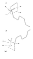
- the connecting ends 46 terminate in a hook structure 48.
- These hook structures 48 comprise a circular, an oval or a cornered shape wherein the legs of the hook structure 38 have to be sufficiently long to reliably fasten the hook structure 48 in said mounting means 32, 34.
- the hook structure 48 encloses by its legs or by its circular, cornered or oval shape a hook plane which is preferably according to the invention oriented substantially perpendicularly to the plane of the support structure 40.
- the above mentioned hook structure 48 is preferably according to the invention fastened in the mounting means 32 at the inner side 30 of the seat frame 20.
- This mounting means 32 is preferably according to the invention formed by a loop.
- This loop 32 as shown according to a preferred embodiment in Figure 2 , comprises a closed shape.
- this loop 32 is integrally worked out from the inside 30 of the seat frame 20.
- the hook structure 48 of the connecting ends 46 are hooked in these loops 32.
- they are preferably according to the invention shaped or profiled. This profile or shape can be realized by a cornered or round or curvilinear profile.
- the forces applied by the support structure 40 are received by the loop 32 and they are deviated in the seat frame 20 preferably according to the invention. Additionally, a low compliance of the loop 32 follows from the profiling or shaping of the loop 32 and, thus, a safe mounting of the support structure 40 within the seat frame 20 is realized.
- the loops 32 extend beyond the plane of the inner side 30 of the seat frame 20. It is, however, also preferred according to the invention that the loops 32 are arranged in the same plane as the inner side 30 of the seat frame 20. As can be seen in Figure 2 , the loops 32 are preferably according to the invention arranged in a window 36. This window 36 supports an easy access of the hook structure 46 to the loop 32 to install the loop structure 46 with low efforts. By the size of the window 36, it is guaranteed that the hook structure 46 does not collide during the hooking in the loop 32 with the inner side 30 of the seat frame 20.
- the window 36 is formed with lower extent having the shape of an elongated hole or slot in parallel alignment with the hook plane.
- the loop 32 is then preferably according to the invention formed by a short profiled or non-profiled bridging of this elongated hole.
- the loop 32 can therefore also be indicated as a web.
- the elongated hole or the slot must only have such a size that the hook structure 48 of the connecting ends 46 can be installed therein and that they can then hook in the loop 32.
- the further advantage follows that the structure of the seat frame 20 is only slightly or not weakened at all by the window 36. Thereby, it is preferably according to the invention prevented that the seat frame 20 brakes in case of an accident of a motor vehicle.
- the loop 32 comprises an additional fastening or an additional safety construction of the hook structure 48 of the connecting ends 46 having the shape of a notch structure 38.
- the preferred notch structure 38 is made of a resilient material like the loop 32.
- the notch structure 38 is formed by a recess or an enclosure the dimension of which are adapted to the diameter of the material of the hook structure 48 of the connecting ends 46. If the hook structure 48 of the connecting ends 46 is installed in the loop 32, it is received from the formed recess or notch of the notch structure 38.
- the notch structure 38 guarantees an additional safety construction of the mounting of the support structure 40 within the loops 32.
- the notch structure 38 is also preferably according to the invention configured in such a way that the hook structure 48 of the connecting ends 46 can engage or latch therein.
- the mounting means 32 of the seat frame 20 are configured as projections or webs 34, as shown in Figure 4 .
- These projections or webs 34 are similarly arranged in windows 36 as the loops 32. It is also preferred according to the invention to arrange the projections 34 in such a way that they extend beyond the side 30 of the seat frame 20 which is directed to the support structure 40 as shown in Figure 4 .
- a further preferred embodiment according to the invention consists in the fact that the projections 34 are arranged within the plane of the inner side 30 of the seat frame 20 (not shown). These projections 34 form something like a tongue within the window 36 in which the connecting ends 46 preferably according to the invention hook in.
- the connecting ends 46 comprise the hook structure 48 already mentioned above or they are preferably according to the invention configured as loop structure 50.
- This loop structure 50 comprises an opening having cornered, circular or oval shape.
- the plane enclosed by the opening is preferably according to the invention substantially perpendicularly oriented to the plane of the support structure 40.
- the same are preferably according to the invention shaped or profiled.
- the same profiles or shapes can be used as already described above in the context of the loops 32.
- the loops 32 or the projections 34 extend preferably according to the invention substantially parallel to the plane of the support structure 40 mounted in the seat frame 20.
- the projections 34 are preferably according to the invention oriented opposed to each other.
- the opposed orientation of the projections 34 indicates the case in which at least two of the projections 34 on one side of the seat frame 20 are arranged in such a way that their free ends are directed to each other.
- An exemplary illustration of this preferred embodiment is depicted in Figure 4 .
- This arrangement has the essential advantage that the support structure 40 cannot be released from the seat frame 20 by a mechanical overload in the direction of one projection 34.
- the mounting of the support structure 40 within the seat frame 20 is secured by the opposed oriented projections 34.
- the connecting ends 46 comprise enlarged ends 60 formed thereon.
- These ends 60 are preferably according to the invention made of a plastic material, metal or similar materials qualified by sufficient stability, durability and wear-resistance.
- the ends 60 are connected by fusing or injecting.
- the connecting ends 46 are preferably according to the invention bent similar to a barb for supporting the mounting of the ends 60.
- the connecting ends 46 with the ends 60 engage preferably according to the invention in slit-shaped openings 65 in the seat frame 20 arranged at the inner side 30 of the seat frame 20 as mounting means 32.
- the slit-shaped openings 65 are preferably according to the invention more narrow configured than the circumference of the ends 60.
- any configuration is preferred according to the invention as shape for the ends 60 which enables retaining of the ends 60 by means of the slit-shaped opening 65.
- the slit-shaped opening 65 runs linearly while comprising at one of its ends a broadening for receiving and mounting the connecting ends 46.
- the slit-shaped openings 65 are preferably according to the invention oriented substantially perpendicularly, parallel or inclined with respect to the plane of the support structure 40. It is furthermore preferred according to the invention to configure the slit-shaped opening 65 having a curvilinear or a cornered run as long as the connecting ends 46 are reliably retained by the seat frame 20 in this manner. It is further preferred according to the invention to provide the slit-shaped opening 65 similar to a keyhole opening 70 as shown in Figure 6 .
- the keyhole opening 70 also provides a slit-shaped opening broadened in its end portion in order to receive and to retain the end 60 or a suitably shaped connecting end 46. Starting from the expanded or broadened end, the keyhole opening 70 tapers so that the connecting ends 46 are retained.
- the keyhole opening 70 cooperates with an end 60 of sufficient broad configuration. It is also preferred according to the invention to let the connecting end 64 terminate in transversely bent ends so that it is reliably retained in the keyhole opening 70 or in the slit-like opening 65.
- said keyhole opening 70 cooperates with a counter element 85 made of plastic material, metal or a similar stable material.
- This counter element 85 is preferably according to the invention mounted on the connecting end 46 shortly before the end 60. After installing the connecting end 46 having said formed end 60 and said counter element 85 in the inner side 30 of the seat frame 20, the connecting end 46 is retained in the keyhole opening 70 of the inner side 20 by the cooperation of the formed end 60 and the counter element 85.
- the counter element 85 generates a clamping effect to prevent a loosening, a shifting or a releasing of the support structure 40 from the seat frame 20.
- the inner side 30 of the seat frame 20 comprises preferably according to the invention slots 90.
- These slots 90 are configured in such a way that they retain a preferred insertable loop element 95 according to the invention.
- This loop element 95 is installed from the side of the seat frame 20 directed away from the inner side 30 and it is independently latched preferably according to the invention in the seat frame 20.
- This latching is preferably according to the invention realized by a latch shape which comprises the loop element 95. It is also preferred according to the invention to provide snapping hooks retaining the loop element 95 in the seat frame 20.
- the loop element 95 is made of metal, plastic material or a similar material resisting the mechanical loading in the seat frame 20.
- the present invention further comprises an advantageous three-step-method in order to install the support structure 40 according to the above mentioned preferred embodiments in the seat frame 20.
- the advantage compared to the prior art consists in the fact that the mounting means 32, 34, 65, 70 are adapted in their shape and orientation to the configuration of the connecting ends 46, 48, 60. Thereby only a displacing of the support structure 40 is carried out essentially in the plane substantially surrounded by the seat frame 20 after the lateral expanding of the support structure 40. Within this plane, however, preferably according to the invention no further displacing of the support structure 40 essentially parallel to the sides of the seat frame 20 is executed to establish a connection. In this manner, work steps while assembling the seat structure as well as time are saved leading to a cost-effective construction.
Landscapes
- Engineering & Computer Science (AREA)
- Aviation & Aerospace Engineering (AREA)
- Transportation (AREA)
- Mechanical Engineering (AREA)
- Seats For Vehicles (AREA)
Applications Claiming Priority (2)
| Application Number | Priority Date | Filing Date | Title |
|---|---|---|---|
| DE10329852.5A DE10329852B4 (de) | 2003-07-02 | 2003-07-02 | Sitzstruktur |
| EP04015663.0A EP1493618B1 (de) | 2003-07-02 | 2004-07-02 | Sitzstruktur |
Related Parent Applications (3)
| Application Number | Title | Priority Date | Filing Date |
|---|---|---|---|
| EP04015663.0 Division | 2004-07-02 | ||
| EP04015663.0A Division EP1493618B1 (de) | 2003-07-02 | 2004-07-02 | Sitzstruktur |
| EP04015663.0A Division-Into EP1493618B1 (de) | 2003-07-02 | 2004-07-02 | Sitzstruktur |
Publications (2)
| Publication Number | Publication Date |
|---|---|
| EP2394846A1 true EP2394846A1 (de) | 2011-12-14 |
| EP2394846B1 EP2394846B1 (de) | 2016-11-30 |
Family
ID=33426822
Family Applications (2)
| Application Number | Title | Priority Date | Filing Date |
|---|---|---|---|
| EP04015663.0A Expired - Lifetime EP1493618B1 (de) | 2003-07-02 | 2004-07-02 | Sitzstruktur |
| EP11177011.1A Expired - Lifetime EP2394846B1 (de) | 2003-07-02 | 2004-07-02 | Sitzstruktur |
Family Applications Before (1)
| Application Number | Title | Priority Date | Filing Date |
|---|---|---|---|
| EP04015663.0A Expired - Lifetime EP1493618B1 (de) | 2003-07-02 | 2004-07-02 | Sitzstruktur |
Country Status (2)
| Country | Link |
|---|---|
| EP (2) | EP1493618B1 (de) |
| DE (2) | DE10329852B4 (de) |
Families Citing this family (9)
| Publication number | Priority date | Publication date | Assignee | Title |
|---|---|---|---|---|
| FR2884776B1 (fr) * | 2005-04-22 | 2007-07-20 | Faurecia Sieges Automobile | Dossier de siege de vehicule automobile comportant une nappe de soutien en fils metalliques |
| ATE538971T1 (de) | 2005-10-28 | 2012-01-15 | L&P Swiss Holding Co | Befestigungsvorrichtung und verfahren und vorrichtung zur herstellung derselben |
| FR2917345A1 (fr) * | 2007-06-12 | 2008-12-19 | Faurecia Sieges Automobile | Dossier de siege comportant une nappe de suspension. |
| DE102008047243A1 (de) * | 2008-09-10 | 2010-03-11 | Brose Fahrzeugteile Gmbh & Co. Kommanditgesellschaft, Coburg | Rückenlehnenstruktur für einen Kraftfahrzeugsitz |
| DE102012012976A1 (de) * | 2012-06-28 | 2014-01-02 | GM Global Technology Operations, LLC (n.d. Ges. d. Staates Delaware) | Befestigungsvorrichtung, Kraftfahrzeugsitz und Kraftfahrzeug sowie Verfahren hierzu |
| JP6234761B2 (ja) * | 2013-09-30 | 2017-11-22 | トヨタ紡織株式会社 | 乗物用シート |
| JP2016203950A (ja) * | 2015-04-28 | 2016-12-08 | テイ・エス テック株式会社 | 車両用シート |
| DE102016217467A1 (de) * | 2016-07-22 | 2018-01-25 | Adient Luxembourg Holding S.à.r.l. | Befestigungsmittel und fahrzeugsitz |
| WO2021178206A1 (en) * | 2020-03-02 | 2021-09-10 | Steelcase Inc. | Body support assembly and methods for the use and assembly thereof |
Citations (5)
| Publication number | Priority date | Publication date | Assignee | Title |
|---|---|---|---|---|
| US3790149A (en) * | 1971-04-26 | 1974-02-05 | Morley Furniture Spring Corp | Spring construction |
| EP0552904A1 (de) | 1992-01-20 | 1993-07-28 | Youngflex S.A. | Verbesserungen bezüglich Sitzanordnungen mit einstellbarer Lendenstütze |
| EP0874575A1 (de) | 1996-01-05 | 1998-11-04 | Youngflex S.A. | Verbesserungen an tragstrukturen zum einbau in einen sitz |
| EP1112709A1 (de) * | 1999-12-27 | 2001-07-04 | Araco Kabushiki Kaisha | Befestigungsvorrichtung für eine Federeinheit |
| US20030085600A1 (en) * | 2001-10-22 | 2003-05-08 | Masatoshi Mori | Lumbar support device |
Family Cites Families (13)
| Publication number | Priority date | Publication date | Assignee | Title |
|---|---|---|---|---|
| GB1133804A (en) * | 1966-12-21 | 1968-11-20 | Nobuyoshi Saito | Frame members adapted to secure sinuous springs |
| IT1118557B (it) | 1979-04-12 | 1986-03-03 | Whitehead Moto Fides Spa Stabi | Sediel per veicoli |
| US5499863A (en) * | 1993-05-17 | 1996-03-19 | Toyota Shatai Kabushiki Kaisha | Seat back frame |
| JP3594162B2 (ja) * | 1997-01-21 | 2004-11-24 | スズキ株式会社 | シートバックフレーム |
| US5911477A (en) * | 1997-05-29 | 1999-06-15 | L&P Property Management Company | Lumbar support structure for automotive vehicle |
| SE512632C2 (sv) * | 1998-04-24 | 2000-04-10 | Ewes Staalfjaeder Ab | Ryggstöd med begränsad fjädring och fjäder |
| GB2341087B (en) * | 1998-09-01 | 2000-09-13 | Youngflex Ag | Suspension assembly |
| GB2342287B (en) | 1998-10-02 | 2001-04-18 | Youngflex Ag | Improvements in or relating to seat suspension arrangements |
| GB2342286B (en) * | 1998-10-02 | 2001-05-09 | Youngflex Ag | Improvements in or relating to seat suspension arrangements |
| JP2000350637A (ja) * | 1999-04-08 | 2000-12-19 | T S Tec Kk | シートフレーム |
| DE60030556T2 (de) * | 1999-11-29 | 2007-05-31 | TS Tech Co., Ltd., Asaka | Rückenlehnrahmen für einen fahrzeugsitz |
| DE10114521A1 (de) | 2001-03-21 | 2002-09-26 | Brose Fahrzeugteile | Sitzlehne für einen Kraftfahrzeugsitz |
| GB0128417D0 (en) * | 2001-11-28 | 2002-01-16 | L&P Swiss Holding Co | Seat suspension arrangement |
-
2003
- 2003-07-02 DE DE10329852.5A patent/DE10329852B4/de not_active Expired - Lifetime
-
2004
- 2004-07-02 DE DE202004021599U patent/DE202004021599U1/de not_active Expired - Lifetime
- 2004-07-02 EP EP04015663.0A patent/EP1493618B1/de not_active Expired - Lifetime
- 2004-07-02 EP EP11177011.1A patent/EP2394846B1/de not_active Expired - Lifetime
Patent Citations (5)
| Publication number | Priority date | Publication date | Assignee | Title |
|---|---|---|---|---|
| US3790149A (en) * | 1971-04-26 | 1974-02-05 | Morley Furniture Spring Corp | Spring construction |
| EP0552904A1 (de) | 1992-01-20 | 1993-07-28 | Youngflex S.A. | Verbesserungen bezüglich Sitzanordnungen mit einstellbarer Lendenstütze |
| EP0874575A1 (de) | 1996-01-05 | 1998-11-04 | Youngflex S.A. | Verbesserungen an tragstrukturen zum einbau in einen sitz |
| EP1112709A1 (de) * | 1999-12-27 | 2001-07-04 | Araco Kabushiki Kaisha | Befestigungsvorrichtung für eine Federeinheit |
| US20030085600A1 (en) * | 2001-10-22 | 2003-05-08 | Masatoshi Mori | Lumbar support device |
Also Published As
| Publication number | Publication date |
|---|---|
| DE10329852B4 (de) | 2023-02-02 |
| DE10329852A1 (de) | 2005-02-03 |
| DE202004021599U1 (de) | 2009-05-14 |
| EP2394846B1 (de) | 2016-11-30 |
| EP1493618A2 (de) | 2005-01-05 |
| EP1493618B1 (de) | 2014-04-23 |
| EP1493618A3 (de) | 2009-04-15 |
Similar Documents
| Publication | Publication Date | Title |
|---|---|---|
| EP1493618B1 (de) | Sitzstruktur | |
| US7407214B2 (en) | Seat adjusting assembly including lead screw and mounting attachment | |
| KR101072697B1 (ko) | 냉각 성형 된 래치 와이어 | |
| EP2045512B1 (de) | Halterung für Bauteile zur Fixierung an einem Paneel | |
| KR19980070875A (ko) | 자동차 좌석용 조정 슬라이드 및 두 개의 상기 슬라이드를 가지는 조정 장치 | |
| KR101496369B1 (ko) | 좌석 벨트 앵커 조립체 | |
| EP1783013A2 (de) | Befestigungseinheit eines Haken oder einer Öse | |
| KR100999143B1 (ko) | 리어 시트백 강도 보강 기구 | |
| KR100750007B1 (ko) | 에어백 모듈 | |
| KR101393789B1 (ko) | 헤드레스트 폴가이드 | |
| GB2517705A (en) | Ceiling system with ceiling element mounting brackets | |
| WO2008038957A1 (en) | Pole for mesh fence | |
| CN111295541A (zh) | 管支撑结构 | |
| US20010046426A1 (en) | Resilient clip fastener | |
| KR102630469B1 (ko) | 차량 래치 | |
| JP2006507184A (ja) | シートベルトリトラクタハウジングの固定装置 | |
| CN110520637B (zh) | 张紧连接器和具有这种张紧连接器的固定组件 | |
| JPH11342714A (ja) | アンチスキッドチェ―ンのサイドホルダ | |
| KR102421187B1 (ko) | 패널의 탈부착이 용이한 안전 펜스 | |
| US7452020B2 (en) | Self locating bracket | |
| KR200482535Y1 (ko) | 차랑용 테더 클립 고정 구조물 | |
| CN111169419A (zh) | 一种汽车座椅结构 | |
| JP4112510B2 (ja) | 屋根役物固定金具 | |
| JP2003267131A (ja) | ドアミラーベースアッセンブリの仮保持部の構造 | |
| JP3568909B2 (ja) | 天井構造 |
Legal Events
| Date | Code | Title | Description |
|---|---|---|---|
| AC | Divisional application: reference to earlier application |
Ref document number: 1493618 Country of ref document: EP Kind code of ref document: P |
|
| AK | Designated contracting states |
Kind code of ref document: A1 Designated state(s): AT BE BG CH CY CZ DE DK EE ES FI FR GB GR HU IE IT LI LU MC NL PL PT RO SE SI SK TR |
|
| PUAI | Public reference made under article 153(3) epc to a published international application that has entered the european phase |
Free format text: ORIGINAL CODE: 0009012 |
|
| 17P | Request for examination filed |
Effective date: 20120529 |
|
| 17Q | First examination report despatched |
Effective date: 20150925 |
|
| GRAP | Despatch of communication of intention to grant a patent |
Free format text: ORIGINAL CODE: EPIDOSNIGR1 |
|
| INTG | Intention to grant announced |
Effective date: 20160622 |
|
| GRAS | Grant fee paid |
Free format text: ORIGINAL CODE: EPIDOSNIGR3 |
|
| GRAA | (expected) grant |
Free format text: ORIGINAL CODE: 0009210 |
|
| AC | Divisional application: reference to earlier application |
Ref document number: 1493618 Country of ref document: EP Kind code of ref document: P |
|
| AK | Designated contracting states |
Kind code of ref document: B1 Designated state(s): AT BE BG CH CY CZ DE DK EE ES FI FR GB GR HU IE IT LI LU MC NL PL PT RO SE SI SK TR |
|
| REG | Reference to a national code |
Ref country code: CH Ref legal event code: EP Ref country code: GB Ref legal event code: FG4D |
|
| REG | Reference to a national code |
Ref country code: AT Ref legal event code: REF Ref document number: 849467 Country of ref document: AT Kind code of ref document: T Effective date: 20161215 |
|
| REG | Reference to a national code |
Ref country code: IE Ref legal event code: FG4D |
|
| REG | Reference to a national code |
Ref country code: DE Ref legal event code: R096 Ref document number: 602004050420 Country of ref document: DE |
|
| REG | Reference to a national code |
Ref country code: NL Ref legal event code: MP Effective date: 20161130 |
|
| REG | Reference to a national code |
Ref country code: AT Ref legal event code: MK05 Ref document number: 849467 Country of ref document: AT Kind code of ref document: T Effective date: 20161130 |
|
| PG25 | Lapsed in a contracting state [announced via postgrant information from national office to epo] |
Ref country code: SE Free format text: LAPSE BECAUSE OF FAILURE TO SUBMIT A TRANSLATION OF THE DESCRIPTION OR TO PAY THE FEE WITHIN THE PRESCRIBED TIME-LIMIT Effective date: 20161130 |
|
| PG25 | Lapsed in a contracting state [announced via postgrant information from national office to epo] |
Ref country code: PT Free format text: LAPSE BECAUSE OF FAILURE TO SUBMIT A TRANSLATION OF THE DESCRIPTION OR TO PAY THE FEE WITHIN THE PRESCRIBED TIME-LIMIT Effective date: 20170330 Ref country code: ES Free format text: LAPSE BECAUSE OF FAILURE TO SUBMIT A TRANSLATION OF THE DESCRIPTION OR TO PAY THE FEE WITHIN THE PRESCRIBED TIME-LIMIT Effective date: 20161130 Ref country code: PL Free format text: LAPSE BECAUSE OF FAILURE TO SUBMIT A TRANSLATION OF THE DESCRIPTION OR TO PAY THE FEE WITHIN THE PRESCRIBED TIME-LIMIT Effective date: 20161130 Ref country code: FI Free format text: LAPSE BECAUSE OF FAILURE TO SUBMIT A TRANSLATION OF THE DESCRIPTION OR TO PAY THE FEE WITHIN THE PRESCRIBED TIME-LIMIT Effective date: 20161130 Ref country code: AT Free format text: LAPSE BECAUSE OF FAILURE TO SUBMIT A TRANSLATION OF THE DESCRIPTION OR TO PAY THE FEE WITHIN THE PRESCRIBED TIME-LIMIT Effective date: 20161130 |
|
| PG25 | Lapsed in a contracting state [announced via postgrant information from national office to epo] |
Ref country code: NL Free format text: LAPSE BECAUSE OF FAILURE TO SUBMIT A TRANSLATION OF THE DESCRIPTION OR TO PAY THE FEE WITHIN THE PRESCRIBED TIME-LIMIT Effective date: 20161130 |
|
| PG25 | Lapsed in a contracting state [announced via postgrant information from national office to epo] |
Ref country code: RO Free format text: LAPSE BECAUSE OF FAILURE TO SUBMIT A TRANSLATION OF THE DESCRIPTION OR TO PAY THE FEE WITHIN THE PRESCRIBED TIME-LIMIT Effective date: 20161130 Ref country code: CZ Free format text: LAPSE BECAUSE OF FAILURE TO SUBMIT A TRANSLATION OF THE DESCRIPTION OR TO PAY THE FEE WITHIN THE PRESCRIBED TIME-LIMIT Effective date: 20161130 Ref country code: SK Free format text: LAPSE BECAUSE OF FAILURE TO SUBMIT A TRANSLATION OF THE DESCRIPTION OR TO PAY THE FEE WITHIN THE PRESCRIBED TIME-LIMIT Effective date: 20161130 Ref country code: EE Free format text: LAPSE BECAUSE OF FAILURE TO SUBMIT A TRANSLATION OF THE DESCRIPTION OR TO PAY THE FEE WITHIN THE PRESCRIBED TIME-LIMIT Effective date: 20161130 Ref country code: DK Free format text: LAPSE BECAUSE OF FAILURE TO SUBMIT A TRANSLATION OF THE DESCRIPTION OR TO PAY THE FEE WITHIN THE PRESCRIBED TIME-LIMIT Effective date: 20161130 |
|
| PG25 | Lapsed in a contracting state [announced via postgrant information from national office to epo] |
Ref country code: BE Free format text: LAPSE BECAUSE OF FAILURE TO SUBMIT A TRANSLATION OF THE DESCRIPTION OR TO PAY THE FEE WITHIN THE PRESCRIBED TIME-LIMIT Effective date: 20161130 Ref country code: BG Free format text: LAPSE BECAUSE OF FAILURE TO SUBMIT A TRANSLATION OF THE DESCRIPTION OR TO PAY THE FEE WITHIN THE PRESCRIBED TIME-LIMIT Effective date: 20170228 Ref country code: IT Free format text: LAPSE BECAUSE OF FAILURE TO SUBMIT A TRANSLATION OF THE DESCRIPTION OR TO PAY THE FEE WITHIN THE PRESCRIBED TIME-LIMIT Effective date: 20161130 |
|
| REG | Reference to a national code |
Ref country code: DE Ref legal event code: R097 Ref document number: 602004050420 Country of ref document: DE |
|
| PLBE | No opposition filed within time limit |
Free format text: ORIGINAL CODE: 0009261 |
|
| STAA | Information on the status of an ep patent application or granted ep patent |
Free format text: STATUS: NO OPPOSITION FILED WITHIN TIME LIMIT |
|
| 26N | No opposition filed |
Effective date: 20170831 |
|
| PG25 | Lapsed in a contracting state [announced via postgrant information from national office to epo] |
Ref country code: SI Free format text: LAPSE BECAUSE OF FAILURE TO SUBMIT A TRANSLATION OF THE DESCRIPTION OR TO PAY THE FEE WITHIN THE PRESCRIBED TIME-LIMIT Effective date: 20161130 |
|
| REG | Reference to a national code |
Ref country code: CH Ref legal event code: PL |
|
| GBPC | Gb: european patent ceased through non-payment of renewal fee |
Effective date: 20170702 |
|
| REG | Reference to a national code |
Ref country code: IE Ref legal event code: MM4A |
|
| REG | Reference to a national code |
Ref country code: FR Ref legal event code: ST Effective date: 20180330 |
|
| PG25 | Lapsed in a contracting state [announced via postgrant information from national office to epo] |
Ref country code: GB Free format text: LAPSE BECAUSE OF NON-PAYMENT OF DUE FEES Effective date: 20170702 Ref country code: CH Free format text: LAPSE BECAUSE OF NON-PAYMENT OF DUE FEES Effective date: 20170731 Ref country code: LI Free format text: LAPSE BECAUSE OF NON-PAYMENT OF DUE FEES Effective date: 20170731 Ref country code: IE Free format text: LAPSE BECAUSE OF NON-PAYMENT OF DUE FEES Effective date: 20170702 |
|
| PG25 | Lapsed in a contracting state [announced via postgrant information from national office to epo] |
Ref country code: FR Free format text: LAPSE BECAUSE OF NON-PAYMENT OF DUE FEES Effective date: 20170731 |
|
| PG25 | Lapsed in a contracting state [announced via postgrant information from national office to epo] |
Ref country code: LU Free format text: LAPSE BECAUSE OF NON-PAYMENT OF DUE FEES Effective date: 20170702 |
|
| PG25 | Lapsed in a contracting state [announced via postgrant information from national office to epo] |
Ref country code: MC Free format text: LAPSE BECAUSE OF FAILURE TO SUBMIT A TRANSLATION OF THE DESCRIPTION OR TO PAY THE FEE WITHIN THE PRESCRIBED TIME-LIMIT Effective date: 20161130 Ref country code: HU Free format text: LAPSE BECAUSE OF FAILURE TO SUBMIT A TRANSLATION OF THE DESCRIPTION OR TO PAY THE FEE WITHIN THE PRESCRIBED TIME-LIMIT; INVALID AB INITIO Effective date: 20040702 |
|
| PG25 | Lapsed in a contracting state [announced via postgrant information from national office to epo] |
Ref country code: CY Free format text: LAPSE BECAUSE OF NON-PAYMENT OF DUE FEES Effective date: 20161130 |
|
| PG25 | Lapsed in a contracting state [announced via postgrant information from national office to epo] |
Ref country code: TR Free format text: LAPSE BECAUSE OF FAILURE TO SUBMIT A TRANSLATION OF THE DESCRIPTION OR TO PAY THE FEE WITHIN THE PRESCRIBED TIME-LIMIT Effective date: 20161130 |
|
| PG25 | Lapsed in a contracting state [announced via postgrant information from national office to epo] |
Ref country code: GR Free format text: LAPSE BECAUSE OF FAILURE TO SUBMIT A TRANSLATION OF THE DESCRIPTION OR TO PAY THE FEE WITHIN THE PRESCRIBED TIME-LIMIT Effective date: 20161130 |
|
| PGFP | Annual fee paid to national office [announced via postgrant information from national office to epo] |
Ref country code: DE Payment date: 20230727 Year of fee payment: 20 |
|
| REG | Reference to a national code |
Ref country code: DE Ref legal event code: R071 Ref document number: 602004050420 Country of ref document: DE |