EP2390600A2 - Refrigerateur magnétique - Google Patents
Refrigerateur magnétique Download PDFInfo
- Publication number
- EP2390600A2 EP2390600A2 EP11173643A EP11173643A EP2390600A2 EP 2390600 A2 EP2390600 A2 EP 2390600A2 EP 11173643 A EP11173643 A EP 11173643A EP 11173643 A EP11173643 A EP 11173643A EP 2390600 A2 EP2390600 A2 EP 2390600A2
- Authority
- EP
- European Patent Office
- Prior art keywords
- heat exchange
- magnetic
- refrigerator
- magnetocaloric material
- accordance
- Prior art date
- Legal status (The legal status is an assumption and is not a legal conclusion. Google has not performed a legal analysis and makes no representation as to the accuracy of the status listed.)
- Withdrawn
Links
Images

Classifications
-
- F—MECHANICAL ENGINEERING; LIGHTING; HEATING; WEAPONS; BLASTING
- F25—REFRIGERATION OR COOLING; COMBINED HEATING AND REFRIGERATION SYSTEMS; HEAT PUMP SYSTEMS; MANUFACTURE OR STORAGE OF ICE; LIQUEFACTION SOLIDIFICATION OF GASES
- F25B—REFRIGERATION MACHINES, PLANTS OR SYSTEMS; COMBINED HEATING AND REFRIGERATION SYSTEMS; HEAT PUMP SYSTEMS
- F25B21/00—Machines, plants or systems, using electric or magnetic effects
-
- F—MECHANICAL ENGINEERING; LIGHTING; HEATING; WEAPONS; BLASTING
- F25—REFRIGERATION OR COOLING; COMBINED HEATING AND REFRIGERATION SYSTEMS; HEAT PUMP SYSTEMS; MANUFACTURE OR STORAGE OF ICE; LIQUEFACTION SOLIDIFICATION OF GASES
- F25B—REFRIGERATION MACHINES, PLANTS OR SYSTEMS; COMBINED HEATING AND REFRIGERATION SYSTEMS; HEAT PUMP SYSTEMS
- F25B1/00—Compression machines, plants or systems with non-reversible cycle
-
- F—MECHANICAL ENGINEERING; LIGHTING; HEATING; WEAPONS; BLASTING
- F25—REFRIGERATION OR COOLING; COMBINED HEATING AND REFRIGERATION SYSTEMS; HEAT PUMP SYSTEMS; MANUFACTURE OR STORAGE OF ICE; LIQUEFACTION SOLIDIFICATION OF GASES
- F25B—REFRIGERATION MACHINES, PLANTS OR SYSTEMS; COMBINED HEATING AND REFRIGERATION SYSTEMS; HEAT PUMP SYSTEMS
- F25B49/00—Arrangement or mounting of control or safety devices
-
- F—MECHANICAL ENGINEERING; LIGHTING; HEATING; WEAPONS; BLASTING
- F25—REFRIGERATION OR COOLING; COMBINED HEATING AND REFRIGERATION SYSTEMS; HEAT PUMP SYSTEMS; MANUFACTURE OR STORAGE OF ICE; LIQUEFACTION SOLIDIFICATION OF GASES
- F25B—REFRIGERATION MACHINES, PLANTS OR SYSTEMS; COMBINED HEATING AND REFRIGERATION SYSTEMS; HEAT PUMP SYSTEMS
- F25B2321/00—Details of machines, plants or systems, using electric or magnetic effects
- F25B2321/002—Details of machines, plants or systems, using electric or magnetic effects by using magneto-caloric effects
- F25B2321/0022—Details of machines, plants or systems, using electric or magnetic effects by using magneto-caloric effects with a rotating or otherwise moving magnet
-
- Y—GENERAL TAGGING OF NEW TECHNOLOGICAL DEVELOPMENTS; GENERAL TAGGING OF CROSS-SECTIONAL TECHNOLOGIES SPANNING OVER SEVERAL SECTIONS OF THE IPC; TECHNICAL SUBJECTS COVERED BY FORMER USPC CROSS-REFERENCE ART COLLECTIONS [XRACs] AND DIGESTS
- Y02—TECHNOLOGIES OR APPLICATIONS FOR MITIGATION OR ADAPTATION AGAINST CLIMATE CHANGE
- Y02B—CLIMATE CHANGE MITIGATION TECHNOLOGIES RELATED TO BUILDINGS, e.g. HOUSING, HOUSE APPLIANCES OR RELATED END-USER APPLICATIONS
- Y02B30/00—Energy efficient heating, ventilation or air conditioning [HVAC]
Definitions
- the present invention relates to a magnetic refrigerator comprising separated hot and cold heat exchange units.
- a conventional magnetic refrigerator is disclosed in U.S. Patent No. 6,668,560 .
- the heat transfer fluid 17 absorbs a heat generated by a magnetocaloric effect of a magnetocaloric material 12 having a magnetic field applied thereto and exits to a hot side outlet port pipe 33 through a hot side outlet port ports 34 to cool the magnetocaloric material 12.
- a hot side sequentially passes the hot side outlet port pipe 33, a valve 71, a pump 60, and a hot heat exchanger 62 and flows into a magnetic heat exchange compartment 13.
- a hot side inlet port pipe 31 the hot side is divided into the hot side inlet port pipe 31 and a cold side outlet port 23, and meets a cold side at a cold side outlet port pipe 24 and proceed to a valve 74.
- the hot side moves from a hot side inlet port 32 to the cold side outlet port pipe 24, the hot side is cooled by passing the magnetocaloric material 12 already cooled by the hot side.
- the cold side that has passed through the valve 74 passes a cold heat exchanger 63 and flows to pipes 83 and 21 to repeat a cycle (a detailed description is omitted. See U.S. Patent No. 6,668,560 for omitted reference numerals).
- the conventional magnetic refrigerator comprises twelve magnetic heat exchange compartments, four valves 71, 72, 73 and 74 and more than 24 pipes, it is difficult to manufacture the conventional magnetic refrigerator.
- a gadolinium having a microscopic size may be lost when the coolant enters or exits the magnetic heat exchange unit.
- a magnetic refrigerator comprising: a magnetic heat exchange unit including a magnetocaloric material for passing a flow of a heat transfer fluid; a hot heat exchange circulating member; a cold heat exchange circulating member; a first solenoid valve connected to a junction of an inlet port of the magnetic heat exchange unit, an outlet port of the hot heat exchange circulating member and an outlet port of the cold heat exchange circulating member; and a second solenoid valve connected to a junction of an outlet port of the magnetic heat exchange unit, an inlet port of the hot heat exchange circulating member and an inlet port of the cold heat exchange circulating member.
- a hot side and a cold side are divided to simplify a structure, to achieve a high heat efficiency, and to be capable of controlling an amount of a heat transfer fluid.
- a heat exchange time may be reduced and a heat exchange efficiency is improved since a pressure of the pump through a closed cycle is sufficiently transferred to the heat transfer fluid.
- the magnet member comprises a permanent magnet and a push-pull unit for pushing the permanent magnet the toward and pulling the permanent magnet away from the magnetic heat exchange unit
- a single magnetic heat exchange unit may be used.
- the push-pull unit comprises a yoke having the permanent magnet disposed at both sides thereof, and a reciprocation transfer member for carrying out a reciprocation of the yoke, wherein the reciprocation transfer member comprises a rack attached to the yoke, a pinion engaged with the rack, and a motor for transferring a rotational power to the pinion.
- the magnet member may be an electromagnet.
- he magnetic heat exchange unit comprises a case including the magnetocaloric material, the inlet port disposed at a top surface of the case and the outlet port disposed on a bottom surface of the case.
- the magnetocaloric material comprises a plurality of magnetocaloric material pieces arranged in the case to have a gap therebetween, a mesh is not require, thereby allowing a smooth flow of the heat transfer fluid.
- each of the plurality of magnetocaloric material pieces comprises a gadolinium plate or a gadolinium rod having a constant circular cross-section in a lengthwise direction.
- the gadolinium rod comprises a groove in the lengthwise direction, a contact area being in contact with the heat transfer fluid is increased, thereby improving the heat exchange efficiency.
- the magnetic heat exchange unit in accordance with the present invention provides following advantages.
- the magnetic refrigerator is divided into the hot heat exchanger and the cold heat exchanger, amounts of the first heat transfer fluid and the second heat transfer fluid are controlled to be different. Therefore, a larger amount of the first heat transfer fluid may be flown to the hot side of the magnetic heat exchange unit to maximize the cooling of the magnetocaloric material.
- the adiabatic state wherein the magnetocaloric material piece is not exposed may be achieved to improve the heat exchange efficiency.
- the hot heat exchange circulating member and the cold heat exchange circulating member embodies the close cycle similar to the closed circuit. Therefore, since the atmospheric pressure does not act on the heat transfer fluid directly, almost no resistance is applied to the pump, thereby reducing the time required for the heat exchange and improving the heat efficiency. This allows a use of a single pump since the pressure adjustment range is increased according to a size and the heat efficiency of the magnetic heat exchange unit.
- the magnetic heat exchange unit is constricted to comprise the case and the plurality of magnetocaloric material pieces disposed in the case to form the gap so that the heat transfer fluid may be flown through the gap, thereby improving the heat exchange efficiency through a uniform contact between the plurality of magnetocaloric material pieces and the heat transfer fluid and eliminating a need for the mesh for the smooth flow of the heat transfer fluid.
- the heat exchange efficiency is improved by increasing the contact area with the heat transfer fluid when the groove is formed on the plurality of magnetocaloric material pieces having the shape of the rod in the lengthwise direction.
- the magnetocaloric material piece is embodied to have the shape of the plate or the rod, the magnetocaloric material piece is not easily lost.
- the magnet member comprises the yoke and the push-pull unit
- the magnetic field may be applied or erased with the magnetic heat exchange unit fixed, and the yoke concentrates the magnetic field toward the direction of the magnetic heat exchange unit to apply the high intensity magnetic field to the magnetic heat exchange unit
- the heat exchange efficiency is improved by increasing the contact area with the heat transfer fluid when the groove is formed on the plurality of magnetocaloric material pieces having the shape of the rod in the lengthwise direction.
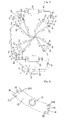
- Fig. 3 is a configuration diagram illustrating a magnetic refrigerator in accordance with a preferred embodiment of the present invention
- Fig. 4 is a diagram illustrating a push-pull member
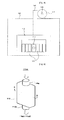
- Fig. 5 is a perspective view illustrating a first magnetic heat exchange unit in accordance with the preferred embodiment of the present invention.
- the magnetic refrigerator in accordance with the preferred embodiment of the present invention comprises a magnetic heat exchange unit 113 including a magnetocaloric material for passing heat transfer fluids 17a and 17b, a magnet member 140 for applying or erasing a magnetic field, a hot heat exchange circulating member, a cold heat exchange circulating member, a first solenoid valve 120a and a second solenoid valve 120b.
- the heat transfer fluids 17a and 17b are divided into a first heat transfer fluid 17a circulating in the hot heat exchange circulating member, and a second heat transfer fluid 17b circulating in the cold heat exchange circulating member to form a cycle.
- the hot heat exchange circulating member comprises a hot heat exchanger 162, a first pipe 130 for moving a first heat transfer fluid 17aa at a cold side outlet of the hot heat exchanger 162 to a hot side of the magnetic heat exchange unit 113, and a second pipe 131 for moving a first heat transfer fluid 17ab to a hot side inlet of the hot heat exchanger 162, wherein the first heat transfer fluid 17ab absorbs a heat of a magnettocaloric material 112 by passing through the hot side of the magnetic heat exchange unit 113.
- the cold heat exchange circulating member comprises a cold heat exchanger 163, a third pipe 132 for moving a second heat transfer fluid 17bb at a hot side outlet of the cold heat exchanger 163 to the cold side of the magnetic heat exchange unit 113, and a fourth pipe 133 for moving a second heat transfer fluid 17bc to a cold side inlet of the cold heat exchanger 163, wherein the second heat transfer fluid 17bc emits a heat to the magnetocaloric material 112 to be cooled by passing through the cold side of the magnetic heat exchange unit 113.
- the first solenoid valve 120a is connected to a junction of an inlet port 115a of the magnetic heat exchange unit 113, an outlet port 130a of the hot heat exchange circulating member and an outlet port 132a of the cold heat exchange circulating member.
- the first solenoid valve 120a is a 3port-2way solenoid valve, wherein a first inlet port thereof is connected to the outlet port 130a of the first pipe 130, and a second inlet port thereof is connected to the outlet port 132a of the third pipe 132.
- An outlet port of the update scheduler 120 is connected to the magnetic heat exchange unit 113, i.e. a fifth pipe 135a connected to the inlet port 115a of the magnetic heat exchange unit 113 to be more specific.
- the second solenoid valve 120b is connected to an outlet port 115b of the magnetic heat exchange unit 113, an inlet port 131b of the hot heat exchange circulating member and an inlet port 133b of the cold heat exchange circulating member.
- a first outlet port of the second solenoid valve 120b is connected to the inlet port 131b of the second pipe 131 and a second outlet port thereof is connected to the inlet port 133b of the fourth pipe 133.
- An inlet port of the second solenoid valve 120b is connected to the magnetic heat exchange unit 113, i.e. a sixth pipe 135b connected to the outlet port 115b of the magnetic heat exchange unit 113 to be more specific.
- the cycle is divided into a hot side cycle and a cold side cycle to control an amount of the heat transfer fluid, to flow more heat transfer fluid to the hot side to be specific, as well as to improve a heat efficiency and simplify a structure.
- the refrigerator further comprises a pump at the hot heat exchange circulating member or the cold heat exchange circulating member.
- the hot heat exchange circulating member and the cold heat exchange circulating member embodies a close cycle similar to a closed circuit. Therefore, since an atmospheric pressure does not act on the heat transfer fluid directly, almost no resistance is applied to the pumps 160 and 161, thereby reducing a time required for the heat exchange and improving the heat efficiency by a smooth circulation of the heat transfer fluid (a pressure adjustment range is increased according to a size and the heat efficiency of the magnetic heat exchange unit).
- the magnetic heat exchange unit 113 comprises the magnetocaloric material 112 which passes the flow of the heat transfer fluid.
- the magnetocaloric material 112 has a characteristic wherein the temperature thereof is changed when the magnetic field is applied.
- the magnetocaloric material 112 comprises a gadolinium (Gd) of a fine powder type.
- the gadolinium has pores having a high osmosis to the flow of the heat transfer fluid, and a superior absorption and emission of a heat.
- the magnetic heat exchange unit 113 in accordance with a first embodiment comprises a case 115 extending vertically, and a plurality of magnetocaloric material pieces 112 disposed in the case 115 to form a gap 114.
- the inlet port 115a is disposed on a top surface of the case 115 to be connected to the outlet port of the fifth pipe 135a, and the outlet port 115b is disposed on a bottom surface of the case 115 to be connected to the outlet port of the sixth pipe 135b.
- the magnetic heat exchange unit 113 may be manufactured by arranging and mounting the magnetocaloric material 112 while the case 115 is disassembled in two parts, and then assembling, bonding or welding the parts.
- the case 115 in accordance with the embodiment may be connected to the inlet port 115a and the outlet port 115b to be supported.
- the support improves the heat exchange efficiency by establishing an adiabatic state wherein the magnetocaloric material 112 of the magnetic heat exchange unit 113 is not exposed.
- the magnetocaloric material 112 which have a shape of a plate manufactured from a gadolinium powder, are disposed in parallel in a manner that the gap 1114 prevents a contact with the case.
- the magnetocaloric material 112 of the gadolinium plate may be a thin foil or a thick sheet according to a flow velocity and the heat exchange rate of the heat transfer fluid.
- the magnetocaloric material 112 having the gap 114 prevents the loss of the material even when a mesh is not used, a contact with the entire the magnetocaloric material 112 as well as a smooth flow is obtained since the heat transfer fluid flows through the gap 114, and a higher heat exchange rate compared to that of the conventional art is obtained since a contact area is larger in case of the gadolinium plate.
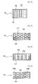
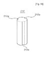
- the magnetic heat exchange unit 213 in accordance with the second embodiment comprises a plurality of magnetocaloric material pieces 212 having a shape of a rod instead of the magnetocaloric material 112 having the shape of the plate. That is, each of the plurality of magnetocaloric material pieces 212 has the shape of the rod having a constant circular cross-section in the lengthwise direction.
- a gap 214 between the plurality of magnetocaloric material pieces 212 having the shape of the rod is formed when in contact or not in contact due to the circular cross-section even when the plurality of magnetocaloric material pieces 212 are randomly arranged such that an effect of the first embodiment is obtained when the heat transfer fluid flows through the gap 214.
- the plurality of magnetocaloric material pieces 1212 having the shape of the rod are inserted in a batch arranged vertically.
- the plurality of magnetocaloric material pieces 212 having the shape of the rod comprises a groove 212a in a lengthwise direction to increase the contact area with the heat transfer fluid, thereby improving the heat exchange efficiency.
- the magnetic heat exchange unit 313 in accordance with the third embodiment comprises a plurality of magnetocaloric material pieces 312 having the shape of the rod arranged to have a gap 314 therebetween similar to the plurality of magnetocaloric material pieces 112 having the shape of the plate of the first embodiment instead of a random arrangement of the plurality of magnetocaloric material pieces 212 having the shape of the rod of the second embodiment.
- the plurality of magnetocaloric material pieces 312 having the shape of the rod are inserted in a batch arranged vertically.
- the plurality of magnetocaloric material pieces 312 having the shape of the rod comprises the groove 212a in the lengthwise direction.
- the magnetic heat exchange unit 413 in accordance with the fourth embodiment comprises a magnetocaloric material 412a having the shape of the rod and a magnetocaloric material 412b having the shape of the plate having a gap 414 therebetween.
- the magnet member 140 may be attached to the magnetic heat exchange unit.
- the magnet member 140 may comprise a permanent magnet 114 disposed at both sides of the case 115 and a push-pull unit for pushing the permanent magnet 114 the toward and pulling the permanent magnet away from the magnetic heat exchange unit 413, or may comprise an electromagnet (not shown) at the both sides of the case 115.
- the push-pull unit comprises a yoke 143 having the permanent magnet 141 disposed at both sides thereof, and a reciprocation transfer member for carrying out a reciprocation of the yoke 143.
- the yoke 143 serves to concentrate the magnetic field of the permanent magnet 141 in a direction of the magnetic heat exchange unit 113 so that the magnetic field having a higher intensity is applied to the magnetic heat exchange unit.
- the reciprocation transfer member may be embodied with a rack 145 attached to the yoke 143, a pinion 147 engaged with the rack 145, and a motor 149 a shaft of which transfers a rotational power to the pinion 147.
- the rack 145 may be embodied by forming a tooth on a rod of a link of the yoke 143 or welding a separate rack to the rod.
- a current may be applied intermittently to embody applying or erasing the magnetic field.
- the cycle of the magnetic refrigerator employing the magnetic heat exchange unit 113 in accordance with the first embodiment of the present invention will now be described wherein the characteristic of the magnetocaloric material is subjected to an experiment by setting an atmospheric temperature which carries out an heat exchange with the hot heat exchanger 162, and an atmospheric temperature which carries out an heat exchange with the cold heat exchanger 163 are set at 26°C respectively, considering a characteristic of the magnetocaloric material wherein a temperature thereof rises by 3°C when the magnetocaloric material is magnetized and drops by 3°C when cooled by the heat transfer fluid.
- the entire system except the magnet member 140 is fixed and the magnet member 140 is subjected to the reciprocation motion between the magnetic heat exchange unit 113 to apply and erase the magnetic field.
- the heat transfer fluid 17aa of the hot side is flown to the magnetic heat exchange unit 113 with a pressure using the solenoid valves 120a and 120b so as to subject the heat (29°C) of the magnetocaloric material heated by the magnetic field to a first cooling (26°C).
- a first cooling 26°C
- the heat transfer fluid 17bb of the cold side (26°C) is flown to the magnetic heat exchange unit 113 with the pressure simultaneously to restore the heat lost in the first cooling.
- the magnetocaloric material absorbs the heat around the material to cool a surrounding.
- the magnetocaloric material is subjected to a second cooling to lower a temperature of the cold side (32°C) such that the hot side emits the heat (29°C) through the hot heat exchanger 162, and the cold side emits a cooled temperature (23°C) through the inlet mesh 16 and the magnetocaloric material pass through the magnetic heat exchange unit again.
- the above-described cycle is repeated.
- the temperature drops from 26°C to 23°C.
- the solenoid valves may easily be programmed digitally, the solenoid valves serve a function of opening a path of the first and the second heat transfer fluids.
- the circulation of the heat transfer fluid is divided into the hot heat exchanger and the cold heat exchanger for the heat exchange of two cycles, thereby simplifying the structure of a magnetic refrigerating cycle.
- the heat transfer fluid at the atmospheric temperature is injected to the magnetocaloric material, the heat transfer fluid is heated and cooled more according to a state of the material to improve an efficiency of the heat exchanger.
- the magnetic refrigerator is divided into the hot heat exchanger and the cold heat exchanger 163, amounts of the first heat transfer fluid and the second heat transfer fluid 17bb are controlled to be different. Therefore, a larger amount of the first heat transfer fluid may be flown to the hot side of the magnetic heat exchange unit to maximize the cooling of the magnetocaloric material.
- a single magnetic heat exchange unit may be used due to a use of the 3port-2way solenoid valve, thereby simplifying the structure, and the cycle is systemized, thereby being capable of controlling a heat exchanging time, a pressure and a velocity of the heat transfer fluid.
- a magnetic refrigerator wherein a hot side and a cold side are divided to simplify a structure, to achieve a high heat efficiency, and to be capable of controlling an amount of a heat transfer fluid can be provied.
Applications Claiming Priority (2)
| Application Number | Priority Date | Filing Date | Title |
|---|---|---|---|
| KR1020050126984A KR100684521B1 (ko) | 2005-12-21 | 2005-12-21 | 자기냉동기 |
| EP06812546A EP1979689A4 (fr) | 2005-12-21 | 2006-11-10 | Refrigerateur magnetique |
Related Parent Applications (1)
| Application Number | Title | Priority Date | Filing Date |
|---|---|---|---|
| EP06812546.7 Division | 2006-11-10 |
Publications (2)
| Publication Number | Publication Date |
|---|---|
| EP2390600A2 true EP2390600A2 (fr) | 2011-11-30 |
| EP2390600A3 EP2390600A3 (fr) | 2013-02-13 |
Family
ID=38104029
Family Applications (2)
| Application Number | Title | Priority Date | Filing Date |
|---|---|---|---|
| EP06812546A Withdrawn EP1979689A4 (fr) | 2005-12-21 | 2006-11-10 | Refrigerateur magnetique |
| EP11173643A Withdrawn EP2390600A3 (fr) | 2005-12-21 | 2006-11-10 | Refrigerateur magnétique |
Family Applications Before (1)
| Application Number | Title | Priority Date | Filing Date |
|---|---|---|---|
| EP06812546A Withdrawn EP1979689A4 (fr) | 2005-12-21 | 2006-11-10 | Refrigerateur magnetique |
Country Status (6)
| Country | Link |
|---|---|
| US (1) | US7644588B2 (fr) |
| EP (2) | EP1979689A4 (fr) |
| JP (1) | JP4825879B2 (fr) |
| KR (1) | KR100684521B1 (fr) |
| CN (1) | CN101341368B (fr) |
| WO (1) | WO2007073038A1 (fr) |
Families Citing this family (89)
| Publication number | Priority date | Publication date | Assignee | Title |
|---|---|---|---|---|
| EP2143151B1 (fr) * | 2007-03-28 | 2011-10-12 | ABB Research Ltd. | Dispositif et procédé pour convertir de l'énergie |
| DE202008001117U1 (de) * | 2007-12-21 | 2009-04-30 | Liebherr-Hausgeräte Ochsenhausen GmbH | Kühl- und/oder Gefriergerät |
| JP4703699B2 (ja) * | 2008-09-04 | 2011-06-15 | 株式会社東芝 | 磁気冷凍用磁性材料、磁気冷凍デバイスおよび磁気冷凍システム |
| FR2942304B1 (fr) * | 2009-02-17 | 2011-08-12 | Cooltech Applications | Generateur thermique magnetocalorique |
| US20110162388A1 (en) * | 2010-01-05 | 2011-07-07 | General Electric Company | Magnetocaloric device |
| US20110225980A1 (en) * | 2010-03-22 | 2011-09-22 | Delta Electronics, Inc. | Magnetic flux generating device and magnetic heat pump |
| FR2959602B1 (fr) * | 2010-04-28 | 2013-11-15 | Cooltech Applications | Procede de generation d'un flux thermique et generateur thermique magnetocalorique |
| US9702594B2 (en) * | 2010-06-07 | 2017-07-11 | Aip Management, Llc | Magnetocaloric refrigerator |
| US8769966B2 (en) * | 2010-08-09 | 2014-07-08 | Cooltech Applications Societe Par Actions Simplifiee | Thermal generator using magnetocaloric material |
| JP5728489B2 (ja) * | 2010-10-29 | 2015-06-03 | 株式会社東芝 | 磁気冷凍システム |
| EP2634511A4 (fr) * | 2010-10-29 | 2014-07-09 | Toshiba Kk | Échangeur de chaleur et système de réfrigération magnétique |
| JP5633746B2 (ja) * | 2011-03-02 | 2014-12-03 | 日立アプライアンス株式会社 | 洗濯乾燥機 |
| JP5338889B2 (ja) | 2011-04-28 | 2013-11-13 | 株式会社デンソー | 磁気ヒートポンプシステム及び該システムを用いた空気調和装置 |
| JP5556739B2 (ja) * | 2011-05-17 | 2014-07-23 | 株式会社デンソー | 磁気ヒートポンプ装置 |
| JP5867255B2 (ja) * | 2011-08-30 | 2016-02-24 | 株式会社デンソー | 熱交換器、熱交換器ユニット、および熱交換器の取り付け方法 |
| JP5966740B2 (ja) | 2011-09-14 | 2016-08-10 | 日産自動車株式会社 | 磁性構造体およびこれを用いた磁気冷暖房装置 |
| US20120111010A1 (en) * | 2011-10-12 | 2012-05-10 | Marc Samuel Geldon | Method and device for producing electrical or mechanical power from ambient heat using magneto-caloric particles |
| KR101238234B1 (ko) | 2011-11-18 | 2013-03-04 | 한국과학기술원 | 최적 유량 조절을 위한 능동형 자기 재생식 냉동기 |
| US20130186107A1 (en) * | 2012-01-20 | 2013-07-25 | Delta Electronics, Inc. | Magnetic refrigeration control system, and method thereof |
| KR101866840B1 (ko) * | 2012-03-26 | 2018-06-14 | 삼성전자주식회사 | 자기냉각장치 |
| JP5677351B2 (ja) * | 2012-03-29 | 2015-02-25 | 株式会社東芝 | 磁気冷凍デバイス及び磁気冷凍システム |
| US8966912B2 (en) * | 2012-05-15 | 2015-03-03 | Delta Electronics, Inc. | Heat exchanging system |
| CN102706028A (zh) * | 2012-05-18 | 2012-10-03 | 华中科技大学 | 一种用于磁制冷机的磁蓄冷装置 |
| CN102809241B (zh) * | 2012-08-02 | 2015-07-29 | 西安市嘉闻材料技术有限公司 | 用于磁制冷机的动密封动态闭环水路循环装置 |
| US10465951B2 (en) | 2013-01-10 | 2019-11-05 | Haier Us Appliance Solutions, Inc. | Magneto caloric heat pump with variable magnetization |
| US9625185B2 (en) | 2013-04-16 | 2017-04-18 | Haier Us Appliance Solutions, Inc. | Heat pump with magneto caloric materials and variable magnetic field strength |
| KR102158130B1 (ko) | 2013-07-04 | 2020-09-21 | 삼성전자주식회사 | 자기 냉각 장치 |
| WO2015017230A1 (fr) | 2013-08-02 | 2015-02-05 | General Electric Company | Ensembles magnéto-caloriques |
| US9851128B2 (en) | 2014-04-22 | 2017-12-26 | Haier Us Appliance Solutions, Inc. | Magneto caloric heat pump |
| US9797630B2 (en) | 2014-06-17 | 2017-10-24 | Haier Us Appliance Solutions, Inc. | Heat pump with restorative operation for magneto caloric material |
| CN104457017B (zh) * | 2014-11-28 | 2017-01-11 | 华南理工大学 | 一种用于磁制冷循环的磁工质封装盒 |
| US10254020B2 (en) | 2015-01-22 | 2019-04-09 | Haier Us Appliance Solutions, Inc. | Regenerator including magneto caloric material with channels for the flow of heat transfer fluid |
| US9631843B2 (en) | 2015-02-13 | 2017-04-25 | Haier Us Appliance Solutions, Inc. | Magnetic device for magneto caloric heat pump regenerator |
| US20180252445A1 (en) * | 2016-03-31 | 2018-09-06 | Fujikura Ltd. | Heat exchanger and magnetic heat pump device |
| WO2017171077A1 (fr) * | 2016-03-31 | 2017-10-05 | 株式会社フジクラ | Échangeur de chaleur et dispositif du type pompe à chaleur magnétique |
| US10299655B2 (en) | 2016-05-16 | 2019-05-28 | General Electric Company | Caloric heat pump dishwasher appliance |
| US10274231B2 (en) | 2016-07-19 | 2019-04-30 | Haier Us Appliance Solutions, Inc. | Caloric heat pump system |
| US10281177B2 (en) | 2016-07-19 | 2019-05-07 | Haier Us Appliance Solutions, Inc. | Caloric heat pump system |
| US10006675B2 (en) | 2016-07-19 | 2018-06-26 | Haier Us Appliance Solutions, Inc. | Linearly-actuated magnetocaloric heat pump |
| US9915448B2 (en) | 2016-07-19 | 2018-03-13 | Haier Us Appliance Solutions, Inc. | Linearly-actuated magnetocaloric heat pump |
| US10047980B2 (en) | 2016-07-19 | 2018-08-14 | Haier Us Appliance Solutions, Inc. | Linearly-actuated magnetocaloric heat pump |
| US10222101B2 (en) | 2016-07-19 | 2019-03-05 | Haier Us Appliance Solutions, Inc. | Linearly-actuated magnetocaloric heat pump |
| US10006673B2 (en) | 2016-07-19 | 2018-06-26 | Haier Us Appliance Solutions, Inc. | Linearly-actuated magnetocaloric heat pump |
| US9869493B1 (en) | 2016-07-19 | 2018-01-16 | Haier Us Appliance Solutions, Inc. | Linearly-actuated magnetocaloric heat pump |
| US10295227B2 (en) | 2016-07-19 | 2019-05-21 | Haier Us Appliance Solutions, Inc. | Caloric heat pump system |
| US10006674B2 (en) | 2016-07-19 | 2018-06-26 | Haier Us Appliance Solutions, Inc. | Linearly-actuated magnetocaloric heat pump |
| US10047979B2 (en) | 2016-07-19 | 2018-08-14 | Haier Us Appliance Solutions, Inc. | Linearly-actuated magnetocaloric heat pump |
| US10006672B2 (en) | 2016-07-19 | 2018-06-26 | Haier Us Appliance Solutions, Inc. | Linearly-actuated magnetocaloric heat pump |
| US10443585B2 (en) | 2016-08-26 | 2019-10-15 | Haier Us Appliance Solutions, Inc. | Pump for a heat pump system |
| US9857106B1 (en) | 2016-10-10 | 2018-01-02 | Haier Us Appliance Solutions, Inc. | Heat pump valve assembly |
| US9857105B1 (en) | 2016-10-10 | 2018-01-02 | Haier Us Appliance Solutions, Inc. | Heat pump with a compliant seal |
| KR101871725B1 (ko) * | 2016-12-01 | 2018-06-27 | 엘지전자 주식회사 | 자기 냉각 시스템 |
| US10386096B2 (en) | 2016-12-06 | 2019-08-20 | Haier Us Appliance Solutions, Inc. | Magnet assembly for a magneto-caloric heat pump |
| US10288326B2 (en) | 2016-12-06 | 2019-05-14 | Haier Us Appliance Solutions, Inc. | Conduction heat pump |
| US11009282B2 (en) | 2017-03-28 | 2021-05-18 | Haier Us Appliance Solutions, Inc. | Refrigerator appliance with a caloric heat pump |
| US10527325B2 (en) | 2017-03-28 | 2020-01-07 | Haier Us Appliance Solutions, Inc. | Refrigerator appliance |
| US10451320B2 (en) | 2017-05-25 | 2019-10-22 | Haier Us Appliance Solutions, Inc. | Refrigerator appliance with water condensing features |
| US10422555B2 (en) | 2017-07-19 | 2019-09-24 | Haier Us Appliance Solutions, Inc. | Refrigerator appliance with a caloric heat pump |
| US10451322B2 (en) | 2017-07-19 | 2019-10-22 | Haier Us Appliance Solutions, Inc. | Refrigerator appliance with a caloric heat pump |
| US11125477B2 (en) | 2017-08-25 | 2021-09-21 | Astronautics Corporation Of America | Drum-type magnetic refrigeration apparatus with improved magnetic-field source |
| WO2019038719A1 (fr) * | 2017-08-25 | 2019-02-28 | Astronautics Corporation Of America | Appareil de réfrigération magnétique de type tambour à anneaux de lit multiples |
| US10520229B2 (en) | 2017-11-14 | 2019-12-31 | Haier Us Appliance Solutions, Inc. | Caloric heat pump for an appliance |
| US11022348B2 (en) | 2017-12-12 | 2021-06-01 | Haier Us Appliance Solutions, Inc. | Caloric heat pump for an appliance |
| US10648705B2 (en) | 2018-04-18 | 2020-05-12 | Haier Us Appliance Solutions, Inc. | Magneto-caloric thermal diode assembly |
| US10648704B2 (en) | 2018-04-18 | 2020-05-12 | Haier Us Appliance Solutions, Inc. | Magneto-caloric thermal diode assembly |
| US10641539B2 (en) | 2018-04-18 | 2020-05-05 | Haier Us Appliance Solutions, Inc. | Magneto-caloric thermal diode assembly |
| US10557649B2 (en) | 2018-04-18 | 2020-02-11 | Haier Us Appliance Solutions, Inc. | Variable temperature magneto-caloric thermal diode assembly |
| US10876770B2 (en) | 2018-04-18 | 2020-12-29 | Haier Us Appliance Solutions, Inc. | Method for operating an elasto-caloric heat pump with variable pre-strain |
| US10551095B2 (en) | 2018-04-18 | 2020-02-04 | Haier Us Appliance Solutions, Inc. | Magneto-caloric thermal diode assembly |
| US10830506B2 (en) | 2018-04-18 | 2020-11-10 | Haier Us Appliance Solutions, Inc. | Variable speed magneto-caloric thermal diode assembly |
| US10782051B2 (en) | 2018-04-18 | 2020-09-22 | Haier Us Appliance Solutions, Inc. | Magneto-caloric thermal diode assembly |
| US10648706B2 (en) | 2018-04-18 | 2020-05-12 | Haier Us Appliance Solutions, Inc. | Magneto-caloric thermal diode assembly with an axially pinned magneto-caloric cylinder |
| US10989449B2 (en) | 2018-05-10 | 2021-04-27 | Haier Us Appliance Solutions, Inc. | Magneto-caloric thermal diode assembly with radial supports |
| US11054176B2 (en) | 2018-05-10 | 2021-07-06 | Haier Us Appliance Solutions, Inc. | Magneto-caloric thermal diode assembly with a modular magnet system |
| US11015842B2 (en) | 2018-05-10 | 2021-05-25 | Haier Us Appliance Solutions, Inc. | Magneto-caloric thermal diode assembly with radial polarity alignment |
| US10684044B2 (en) | 2018-07-17 | 2020-06-16 | Haier Us Appliance Solutions, Inc. | Magneto-caloric thermal diode assembly with a rotating heat exchanger |
| US11092364B2 (en) | 2018-07-17 | 2021-08-17 | Haier Us Appliance Solutions, Inc. | Magneto-caloric thermal diode assembly with a heat transfer fluid circuit |
| JP7185131B2 (ja) * | 2018-09-14 | 2022-12-07 | ダイキン工業株式会社 | 磁気冷凍モジュール |
| CN109323481A (zh) * | 2018-10-22 | 2019-02-12 | 珠海格力电器股份有限公司 | 一种蓄冷床及具有其的磁制冷机 |
| CN109612150B (zh) * | 2018-11-15 | 2020-06-26 | 珠海格力电器股份有限公司 | 一种磁制冷系统 |
| CN109539625B (zh) * | 2018-12-06 | 2020-08-28 | 天津商业大学 | 一种基于脉冲磁场的可调节型磁制冷装置 |
| US11149994B2 (en) | 2019-01-08 | 2021-10-19 | Haier Us Appliance Solutions, Inc. | Uneven flow valve for a caloric regenerator |
| US11168926B2 (en) | 2019-01-08 | 2021-11-09 | Haier Us Appliance Solutions, Inc. | Leveraged mechano-caloric heat pump |
| US11274860B2 (en) | 2019-01-08 | 2022-03-15 | Haier Us Appliance Solutions, Inc. | Mechano-caloric stage with inner and outer sleeves |
| US11193697B2 (en) | 2019-01-08 | 2021-12-07 | Haier Us Appliance Solutions, Inc. | Fan speed control method for caloric heat pump systems |
| US11112146B2 (en) | 2019-02-12 | 2021-09-07 | Haier Us Appliance Solutions, Inc. | Heat pump and cascaded caloric regenerator assembly |
| US11015843B2 (en) | 2019-05-29 | 2021-05-25 | Haier Us Appliance Solutions, Inc. | Caloric heat pump hydraulic system |
| JP6899981B1 (ja) * | 2020-05-14 | 2021-07-07 | 三菱電機株式会社 | 磁気冷凍機 |
| JP7362010B1 (ja) | 2023-03-20 | 2023-10-16 | 三菱電機株式会社 | 磁気冷凍装置 |
Citations (1)
| Publication number | Priority date | Publication date | Assignee | Title |
|---|---|---|---|---|
| US6668560B2 (en) | 2001-12-12 | 2003-12-30 | Astronautics Corporation Of America | Rotating magnet magnetic refrigerator |
Family Cites Families (23)
| Publication number | Priority date | Publication date | Assignee | Title |
|---|---|---|---|---|
| US4030312A (en) * | 1976-04-07 | 1977-06-21 | Shantzer-Wallin Corporation | Heat pumps with solar heat source |
| JPS5843367A (ja) * | 1981-09-09 | 1983-03-14 | 富士通株式会社 | 磁気冷凍機 |
| US4459811A (en) * | 1983-03-28 | 1984-07-17 | The United States Of America As Represented By The United States Department Of Energy | Magnetic refrigeration apparatus and method |
| JPS59180254A (ja) * | 1983-03-31 | 1984-10-13 | 株式会社東芝 | 連続磁気冷凍装置 |
| JPS60259870A (ja) * | 1984-06-05 | 1985-12-21 | 株式会社東芝 | 磁気冷凍装置 |
| JPS6141859A (ja) * | 1984-08-02 | 1986-02-28 | 科学技術庁長官官房会計課長 | 磁気冷凍装置 |
| JP2513608B2 (ja) * | 1985-08-30 | 1996-07-03 | 株式会社東芝 | 磁気冷凍方法および装置 |
| JPS62288456A (ja) * | 1986-06-09 | 1987-12-15 | 株式会社日立製作所 | 磁気冷凍方法 |
| JPH01111174A (ja) * | 1987-10-23 | 1989-04-27 | Matsushita Electric Ind Co Ltd | 磁性冷暖房装置 |
| JPH0370944A (ja) * | 1989-08-08 | 1991-03-26 | Matsushita Electric Ind Co Ltd | 磁気冷凍機を使用した空気調和装置 |
| JP3070944B2 (ja) | 1990-10-29 | 2000-07-31 | コニカ株式会社 | 放射線画像変換パネルの製造方法 |
| US5249424A (en) * | 1992-06-05 | 1993-10-05 | Astronautics Corporation Of America | Active magnetic regenerator method and apparatus |
| US5357756A (en) * | 1993-09-23 | 1994-10-25 | Martin Marietta Energy Systems, Inc. | Bipolar pulse field for magnetic refrigeration |
| US6347528B1 (en) * | 1999-07-26 | 2002-02-19 | Denso Corporation | Refrigeration-cycle device |
| ES2284683T3 (es) * | 2000-08-09 | 2007-11-16 | Astronautics Corporation Of America | Aparato de refrigeracion magnetica de sustrato rotativo. |
| JP2002195683A (ja) * | 2000-12-20 | 2002-07-10 | Denso Corp | 磁気温調装置 |
| US6676772B2 (en) * | 2001-03-27 | 2004-01-13 | Kabushiki Kaisha Toshiba | Magnetic material |
| US6957666B2 (en) * | 2001-06-26 | 2005-10-25 | Cafe Engineering | Spring valve implemented flow control valves |
| US6502404B1 (en) * | 2001-07-31 | 2003-01-07 | Praxair Technology, Inc. | Cryogenic rectification system using magnetic refrigeration |
| US6595004B1 (en) * | 2002-04-19 | 2003-07-22 | International Business Machines Corporation | Apparatus and methods for performing switching in magnetic refrigeration systems using thermoelectric switches |
| JP4213986B2 (ja) * | 2003-04-17 | 2009-01-28 | アスモ株式会社 | 温度調整装置 |
| FR2861454B1 (fr) * | 2003-10-23 | 2006-09-01 | Christian Muller | Dispositif de generation de flux thermique a materiau magneto-calorique |
| FR2868519B1 (fr) * | 2004-03-30 | 2006-06-16 | Christian Muller | Generateur thermique a materiau magneto-calorique et procede de generation de thermies |
-
2005
- 2005-12-21 KR KR1020050126984A patent/KR100684521B1/ko not_active IP Right Cessation
-
2006
- 2006-11-10 EP EP06812546A patent/EP1979689A4/fr not_active Withdrawn
- 2006-11-10 EP EP11173643A patent/EP2390600A3/fr not_active Withdrawn
- 2006-11-10 JP JP2008547086A patent/JP4825879B2/ja not_active Expired - Fee Related
- 2006-11-10 CN CN2006800481715A patent/CN101341368B/zh not_active Expired - Fee Related
- 2006-11-10 WO PCT/KR2006/004713 patent/WO2007073038A1/fr active Application Filing
-
2008
- 2008-06-20 US US12/143,459 patent/US7644588B2/en not_active Expired - Fee Related
Patent Citations (1)
| Publication number | Priority date | Publication date | Assignee | Title |
|---|---|---|---|---|
| US6668560B2 (en) | 2001-12-12 | 2003-12-30 | Astronautics Corporation Of America | Rotating magnet magnetic refrigerator |
Also Published As
| Publication number | Publication date |
|---|---|
| US7644588B2 (en) | 2010-01-12 |
| WO2007073038A1 (fr) | 2007-06-28 |
| EP1979689A1 (fr) | 2008-10-15 |
| CN101341368B (zh) | 2010-04-21 |
| US20090019859A1 (en) | 2009-01-22 |
| EP1979689A4 (fr) | 2009-05-13 |
| JP2009520946A (ja) | 2009-05-28 |
| EP2390600A3 (fr) | 2013-02-13 |
| KR100684521B1 (ko) | 2007-02-20 |
| CN101341368A (zh) | 2009-01-07 |
| JP4825879B2 (ja) | 2011-11-30 |
Similar Documents
| Publication | Publication Date | Title |
|---|---|---|
| EP2390600A2 (fr) | Refrigerateur magnétique | |
| US20080314049A1 (en) | Active Magnetic Refrigerator | |
| KR100761666B1 (ko) | 능동자기냉동기 | |
| US7603865B2 (en) | Magnetic refrigerator | |
| RU2436022C2 (ru) | Генератор тепла, содержащий магнитокалорический материал | |
| US9134051B2 (en) | Magnetocaloric heat generator | |
| AU2004286064B2 (en) | Device for generating a thermal flux with magneto-caloric material | |
| US9310110B2 (en) | Thermoelectric drinking apparatus and thermoelectric heat pump | |
| US8820093B2 (en) | Magnetocaloric heat generator | |
| US20050047284A1 (en) | Heat exchanger using magnetic heat storage material included in cooling water | |
| KR100684527B1 (ko) | 자기냉동기용 자기열교환유닛 | |
| US9091465B2 (en) | Magnetocaloric heat generator | |
| JP6865902B1 (ja) | 磁気温調システム | |
| JP2016513784A (ja) | 熱装置 | |
| KR20070066155A (ko) | 자기열교환유닛 및 이를 채택한 자기냉동기 | |
| KR20240010234A (ko) | 카트리지 교체형 자기 냉각 시스템 | |
| JP2016145655A (ja) | 熱交換器及び磁気ヒートポンプ装置 | |
| JP2016151393A (ja) | 熱交換器及び磁気ヒートポンプ装置 | |
| DE102012110718A1 (de) | Wärmeaustauschsystem | |
| JPS5856531Y2 (ja) | 冷暖房装置 | |
| JPS627979A (ja) | 熱駆動ポンプ |
Legal Events
| Date | Code | Title | Description |
|---|---|---|---|
| AC | Divisional application: reference to earlier application |
Ref document number: 1979689 Country of ref document: EP Kind code of ref document: P |
|
| AK | Designated contracting states |
Kind code of ref document: A2 Designated state(s): DE FR GB IT NL |
|
| PUAI | Public reference made under article 153(3) epc to a published international application that has entered the european phase |
Free format text: ORIGINAL CODE: 0009012 |
|
| RIN1 | Information on inventor provided before grant (corrected) |
Inventor name: SHIN, SEUNG HOON Inventor name: LEE, DONG KWAN |
|
| RIN1 | Information on inventor provided before grant (corrected) |
Inventor name: LEE, DONG KWAN Inventor name: SHIN, SEUNG HOON |
|
| PUAL | Search report despatched |
Free format text: ORIGINAL CODE: 0009013 |
|
| AK | Designated contracting states |
Kind code of ref document: A3 Designated state(s): DE FR GB IT NL |
|
| RIC1 | Information provided on ipc code assigned before grant |
Ipc: F25B 21/00 20060101AFI20130109BHEP |
|
| 17P | Request for examination filed |
Effective date: 20130812 |
|
| RBV | Designated contracting states (corrected) |
Designated state(s): DE FR GB IT NL |
|
| STAA | Information on the status of an ep patent application or granted ep patent |
Free format text: STATUS: THE APPLICATION IS DEEMED TO BE WITHDRAWN |
|
| 18D | Application deemed to be withdrawn |
Effective date: 20150602 |