EP2390144A1 - Airbag rideau - Google Patents
Airbag rideau Download PDFInfo
- Publication number
- EP2390144A1 EP2390144A1 EP11004443A EP11004443A EP2390144A1 EP 2390144 A1 EP2390144 A1 EP 2390144A1 EP 11004443 A EP11004443 A EP 11004443A EP 11004443 A EP11004443 A EP 11004443A EP 2390144 A1 EP2390144 A1 EP 2390144A1
- Authority
- EP
- European Patent Office
- Prior art keywords
- bag section
- curtain
- curtain bag
- vehicle
- section
- Prior art date
- Legal status (The legal status is an assumption and is not a legal conclusion. Google has not performed a legal analysis and makes no representation as to the accuracy of the status listed.)
- Granted
Links
Images


Classifications
-
- B—PERFORMING OPERATIONS; TRANSPORTING
- B60—VEHICLES IN GENERAL
- B60R—VEHICLES, VEHICLE FITTINGS, OR VEHICLE PARTS, NOT OTHERWISE PROVIDED FOR
- B60R21/00—Arrangements or fittings on vehicles for protecting or preventing injuries to occupants or pedestrians in case of accidents or other traffic risks
- B60R21/02—Occupant safety arrangements or fittings, e.g. crash pads
- B60R21/16—Inflatable occupant restraints or confinements designed to inflate upon impact or impending impact, e.g. air bags
- B60R21/20—Arrangements for storing inflatable members in their non-use or deflated condition; Arrangement or mounting of air bag modules or components
- B60R21/213—Arrangements for storing inflatable members in their non-use or deflated condition; Arrangement or mounting of air bag modules or components in vehicle roof frames or pillars
-
- B—PERFORMING OPERATIONS; TRANSPORTING
- B60—VEHICLES IN GENERAL
- B60R—VEHICLES, VEHICLE FITTINGS, OR VEHICLE PARTS, NOT OTHERWISE PROVIDED FOR
- B60R21/00—Arrangements or fittings on vehicles for protecting or preventing injuries to occupants or pedestrians in case of accidents or other traffic risks
- B60R21/02—Occupant safety arrangements or fittings, e.g. crash pads
- B60R21/16—Inflatable occupant restraints or confinements designed to inflate upon impact or impending impact, e.g. air bags
- B60R21/23—Inflatable members
- B60R21/231—Inflatable members characterised by their shape, construction or spatial configuration
- B60R21/232—Curtain-type airbags deploying mainly in a vertical direction from their top edge
-
- B—PERFORMING OPERATIONS; TRANSPORTING
- B60—VEHICLES IN GENERAL
- B60R—VEHICLES, VEHICLE FITTINGS, OR VEHICLE PARTS, NOT OTHERWISE PROVIDED FOR
- B60R21/00—Arrangements or fittings on vehicles for protecting or preventing injuries to occupants or pedestrians in case of accidents or other traffic risks
- B60R21/02—Occupant safety arrangements or fittings, e.g. crash pads
- B60R21/16—Inflatable occupant restraints or confinements designed to inflate upon impact or impending impact, e.g. air bags
- B60R21/23—Inflatable members
- B60R21/231—Inflatable members characterised by their shape, construction or spatial configuration
- B60R21/2334—Expansion control features
- B60R21/2338—Tethers
-
- B—PERFORMING OPERATIONS; TRANSPORTING
- B60—VEHICLES IN GENERAL
- B60R—VEHICLES, VEHICLE FITTINGS, OR VEHICLE PARTS, NOT OTHERWISE PROVIDED FOR
- B60R21/00—Arrangements or fittings on vehicles for protecting or preventing injuries to occupants or pedestrians in case of accidents or other traffic risks
- B60R21/02—Occupant safety arrangements or fittings, e.g. crash pads
- B60R21/16—Inflatable occupant restraints or confinements designed to inflate upon impact or impending impact, e.g. air bags
- B60R2021/161—Inflatable occupant restraints or confinements designed to inflate upon impact or impending impact, e.g. air bags characterised by additional means for controlling deployment trajectory
-
- B—PERFORMING OPERATIONS; TRANSPORTING
- B60—VEHICLES IN GENERAL
- B60R—VEHICLES, VEHICLE FITTINGS, OR VEHICLE PARTS, NOT OTHERWISE PROVIDED FOR
- B60R21/00—Arrangements or fittings on vehicles for protecting or preventing injuries to occupants or pedestrians in case of accidents or other traffic risks
- B60R21/02—Occupant safety arrangements or fittings, e.g. crash pads
- B60R21/16—Inflatable occupant restraints or confinements designed to inflate upon impact or impending impact, e.g. air bags
- B60R21/23—Inflatable members
- B60R21/237—Inflatable members characterised by the way they are folded
Definitions
- Embodiments described herein relate to a curtain airbag having a curtain bag section for deploying from a section at the side edge of a vehicle roof and inflating along the side wall of the vehicle compartment, and in particular to a curtain airbag for preventing an interior member interfering with deployment and inflation.
- An airbag device such as one provided to a car retains and protects an occupant by a bag section deploying and inflating by being injected with deployment gas, when there is a collision.
- a curtain airbag having a curtain bag section that deploys downwards in a curtain shape along a side window from a section at the side edge of the roof of a vehicle.
- JP-A-2006-137413 describes increasing the bag stroke of a curtain bag section used for impact absorption without excessively increasing the volume within the bag.
- a tension panel functioning as a tether, is provided spanning along the top-bottom direction at the vehicle width direction outside of the curtain bag section.
- the tension panel retains the bag body in a bent or curved shape so as to form a projection facing towards the vehicle compartment inside, such that the curtain bag section adopts a D-shape in cross-section when viewed along the front-rear direction.
- Exemplary embodiments of the present invention are to provide a curtain airbag using a simple configuration to prevent interference from an interior member during deployment and inflation of a curtain bag section.
- a curtain airbag as defined in claim 1 is provided.
- the curtain airbag including: a curtain bag section configured with cloth panels joined to each other, the curtain bag section being housed in a folded state within a side edge portion of a roof of a vehicle before a deployment gas is injected into the curtain bag section, wherein the curtain bag section deploys and inflates downwards from the roof of the vehicle when the deployment gas is injected into the curtain bag section; a collision detector configured to detect at least one of a collision of the vehicle and signs of an imminent collision of the vehicle; a gas generator configured to supply the deployment gas to the curtain bag section in response to a detection result of the collision detector; and a guide member joined to the curtain bag section and configured with a cloth panel, the guide member being rolled up to cover the curtain bag section that has been folded before deployment and inflation of the curtain bag section, when viewed from a vehicle width direction
- the curtain bag section deploys and inflates downwards from the roof of the vehicle such that the guide member guides the curtain bag section, when the deployment gas is injected into the curtain bag section.
- a position of the guide member in a vehicle longitudinal direction is overlapped with a position of an interior member in the vehicle longitudinal direction.
- the curtain airbag of a first exemplary embodiment is, for example, installed in an automobile, such as a car.
- a curtain bag section of the curtain airbag is housed in a folded state inside trim at a section at the side edge of the roof prior to use.
- the curtain bag section deploys and inflates downwards substantially along the side window glass.
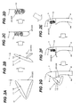
- a vehicle 1 has an A-pillar 2, a front door glass 3, a B-pillar 4, a rear door glass 5, and a C-pillar 6, disposed in this sequence from the front.
- the A-pillar 2 is a pillar shaped section extending along the vehicle left and right edge portions of the front windscreen.
- the front door glass 3 is a side window glass installed to the front door so as to be capable of being raised and lowered.
- the front edge portion of the front door glass 3 is disposed along the rear edge portion of the A-pillar 2.
- the B-pillar 4 is a pillar shaped section provided between the rear edge portion of the front door glass 3 and the front edge portion of the B-pillar 4.
- a trim 4A this being a decorative member (pillar trim) formed for example from a resin, is attached at the vehicle compartment inside of the B-pillar 4.
- the rear door glass 5 is a side door window glass installed to the rear door so as to be capable of being raised and lowered.
- the C-pillar 6 is a pillar shaped section extending along the rear edge portion of the rear door glass 5.
- a roof side rail 7 is provided extending in the vehicle front-rear direction spanning between top end portions of each of the pillars.
- the roof side rail 7 is a vehicle body structural member disposed at a section at each of the side edges of the roof.
- the curtain airbag is configured with an inflator, collision detector, inflator controller, these not being shown in the drawings, and a curtain bag section 10 illustrated in Fig. 1 .
- the inflator is a gas generator for generating inflation gas by means of an explosive, for example, and is mounted to a portion of the C-pillar 6.
- the collision detector for example, is a device provided with plural accelerometers placed at various locations on the vehicle for detecting a vehicle collision.
- the inflator controller determines whether or not to deploy and inflate the curtain bag section 10 based on output from the collision detector.
- the inflator controller outputs a control signal to the inflator when deployment is required, thereby causing the inflator to generate deployment gas.
- the curtain bag section 10 is formed in a bag shape by stitching together a front panel 11 and a rear panel 12.
- the front panel 11 and the rear panel 12 are made from cloth panel treated with a coating to obtain the desired strength, gas sealing ability and heat resistance.
- the front panel 11 and the rear panel 12 are formed in substantially the same shape as each other, and, after deployment is complete, become disposed at the occupant side (vehicle width direction inside) and vehicle outside (vehicle width direction outside), respectively.
- the curtain bag section 10 includes a front chamber 13, a rear chamber 14, a communication section 15 and a gas injection inlet 16 made by stitching together the front panel 11 and the rear panel 12 with stitching S.
- a sealing agent is disposed in bands between the front panel 11 and the rear panel 12 at locations stitched together by the stitching S.
- the top edge of the curtain bag section 10 is formed with plural tabs T used for fixing the curtain bag section 10 to the vehicle 1.
- the front chamber 13 and the rear chamber 14 are sections that restrain the head, shoulders and upper arms of occupant(s) seated in the front and/or rear seats, respectively, when deployed.
- the front chamber 13 and the rear chamber 14 are formed into bag shapes by stitching together around their peripheries with the stitching S.
- the front chamber 13 is disposed in a region overlapping with the vehicle 1 front-rear direction position of the front door glass 3.
- the rear chamber 14 is disposed in a region overlapping with the vehicle 1 front-rear direction position of the rear door glass 5.
- Stitching S1 is formed at central portions of the front chamber 13 and the rear chamber 14 to restrict the thickness of the curtain bag section 10 when inflated.
- the stitching S1 branches off from the stitching S at the bottom edges of the front chamber 13 and the rear chamber 14, and extends out across central portions, with several sets of the stitching S1 provided at intervals along the front-rear direction.
- the stitching S1 is formed at the top ends with circular shapes, in order to avoid stress concentration, and holes are formed through each of the panels at central portions of these circular shapes.
- the communication section 15 communicates the front chamber 13 with the rear chamber 14, and is a communication path capable of supplying deployment gas from the rear chamber 14 side to the front chamber 13 side during deployment.
- the communication section 15 is extends substantially horizontally and spans between a rear portion at the top edge of the front chamber 13 and a front portion at the top edge of the rear chamber 14.
- the gas injection inlet 16 is provided at a rear portion at the top edge of the rear chamber 14, and is a portion to which the inflator, not shown in the drawings, is connected through an injection tube channel, not shown in the drawings. Deployment gas is injected between the front panel 11 and the rear panel 12 at the gas injection inlet 16.
- a rear tension panel 20, explained below, is joined to the curtain bag section 10 of the first exemplary embodiment. As shown in Figs. 2A to 2E , the rear tension panel 20 functions to maintain the curtain bag section 10 after deployment and inflation such that when viewed from the vehicle front-rear direction, a central portion of the curtain bag section 10 adopts a curved or bent shape so as to project out to the vehicle compartment inside with respect to the top and bottom edges of the curtain bag section 10.
- the rear tension panel 20 is provided at the vehicle width direction outside (glass side) with respect to the rear panel 12 of the curtain bag section 10, and the top edge portion and bottom edge portion of the rear tension panel 20 are stitched together to the top edge portion and bottom edge portion of the front panel 11 and the rear panel 12 at the same time as stitching together with the stitching S.
- the rear tension panel 20 is formed with a smaller up-down direction dimension than that of the rear panel 12, and the separation between the locations for stitching together at the top and bottom of the rear tension panel 20 is set smaller than the separation between the locations for stitching together at the top and bottom of the rear panel 12 when laid out on a flat surface.
- Slits 21, 22 are formed to the rear tension panel 20.
- the slits 21, 22 are cuts formed in the up-down direction across substantially the whole height of the rear tension panel 20.
- the slits 21, 22 are disposed at the front and rear of the B-pillar 4, respectively. Round holes are formed at the top and bottom end portions of the slits 21, 22, disposed adjacent to the top and bottom stitched together locations of the rear tension panel 20, in order to prevent stress concentration.
- a guide section 23, for preventing interference to the curtain bag section 10 from the trim 4A during deployment of the curtain bag section 10, is configured by a region of the rear tension panel 20 between the slits 21, 22.
- the guide section 23 is connected at its top and bottom end portions to other portions of the rear tension panel 20 and to the top and bottom end portions of the curtain bag section 10. Detailed explanation is given later regarding functioning of the guide section 23.
- a lower portion of the curtain bag section 10 is folded in between the other portions of the curtain bag section 10 and the rear tension panel 20 such that when laid out on a flat surface the curtain bag section 10 is substantially the same height as the rear tension panel 20.
- the curtain bag section 10 in such a folded state is shown as a single bold line (this also applies to Figs. 3A to 3F ).
- configuration may be made such that a central portion of the curtain bag section 10 is folded between other portions of the curtain bag section 10 and the rear tension panel 20.
- the top half portion of the curtain bag section 10 is folded into a serpent shape by folding along plural fold lines, disposed at substantially even intervals and extending substantially horizontally, in sequence alternately in opposite directions.
- the lower half portion of the curtain bag section 10 is then wound up in a roll shape via the vehicle width direction inside (the left hand side in the diagram).
- the portion of the guide section 23 of the rear tension panel 20 where the curtain bag section 10 is rolled is rolled in with the curtain bag section 10, however the portion of the guide section 23 where the curtain bag section 10 is in a serpent shape is not folded in therewith.
- a portion of the guide section 23 can be placed in a slack state enabling it to droop down.
- the above described slack portion of the guide section 23 is wound around from the lower portion of the curtain bag section 10 when installed in a vehicle, via the vehicle width direction inside, and up over to the side of the upper portion of the curtain bag section 10.
- the curtain bag section 10 and the rear tension panel 20 are attached to the roof side rail 7 of the vehicle 1 in this state, as shown in Fig. 2E .
- the curtain bag section 10 is, for example, temporarily fixed to maintain the folded state of the curtain bag section 10, by using, for example, tape, thread, or a cover that ruptures during deployment.
- the curtain bag section 10 is maintained in a curved or bent state such that the height direction central portion of the curtain bag section 10 projects out towards the vehicle width direction inside.
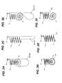
- Figs. 3A to 3G are schematic cross-sections showing folded states of the curtain bag section 10 and the rear tension panel 20 at portions other than at the guide section 23, and variations on folding methods.
- the vehicle width direction inside (vehicle compartment inside) is illustrated on the left hand side of the drawings.
- the entire curtain bag section 10 is folded in a serpent shape.
- the upper portion of the curtain bag section 10 is folded in a serpent shape, and the lower portion of the curtain bag section 10 is wound up in a roll in the opposite direction to the first exemplary embodiment, namely towards the vehicle width direction outside.
- portions of the rear tension panel 20 other than at the guide section 23 are folded in their entirety in with the curtain bag section 10, without a slack portion.
- a curtain airbag of the second exemplary embodiment is provided with a guide panel 30, explained below, in place of the rear tension panel 20 of the first exemplary embodiment.
- the guide panel 30 is a cloth panel of substantially rectangular shape provided in a section aligned with the B-pillar 4 and joined to a bottom edge portion of a curtain bag section 10.
- the edge of the guide panel 30 on the opposite side to the side joined to the curtain bag section 10 is not joined to any other member and adopts a free state (a state enabling it to flop down).
- the guide panel 30 is, similarly to the guide section 23 of the first exemplary embodiment, wound from the bottom side of the curtain bag section 10, via the vehicle width direction inside, up over to the top side of the curtain bag section 10.
Landscapes
- Engineering & Computer Science (AREA)
- Mechanical Engineering (AREA)
- Air Bags (AREA)
Applications Claiming Priority (1)
| Application Number | Priority Date | Filing Date | Title |
|---|---|---|---|
| JP2010123748A JP5502599B2 (ja) | 2010-05-31 | 2010-05-31 | カーテンエアバッグ装置 |
Publications (2)
| Publication Number | Publication Date |
|---|---|
| EP2390144A1 true EP2390144A1 (fr) | 2011-11-30 |
| EP2390144B1 EP2390144B1 (fr) | 2013-05-08 |
Family
ID=44483985
Family Applications (1)
| Application Number | Title | Priority Date | Filing Date |
|---|---|---|---|
| EP11004443.5A Not-in-force EP2390144B1 (fr) | 2010-05-31 | 2011-05-31 | Véhicule avec un airbag rideau |
Country Status (4)
| Country | Link |
|---|---|
| US (1) | US8714587B2 (fr) |
| EP (1) | EP2390144B1 (fr) |
| JP (1) | JP5502599B2 (fr) |
| CN (1) | CN102294986B (fr) |
Cited By (5)
| Publication number | Priority date | Publication date | Assignee | Title |
|---|---|---|---|---|
| CN105292044A (zh) * | 2014-07-14 | 2016-02-03 | 福特全球技术公司 | 具有保护片的帘式安全气囊 |
| CN108463378A (zh) * | 2016-01-15 | 2018-08-28 | 奥托立夫开发公司 | 帘式气囊装置及其对车辆的安装结构 |
| US10384636B2 (en) | 2015-04-20 | 2019-08-20 | Autoliv Development Ab | Curtain airbag device |
| US10479314B2 (en) | 2017-03-08 | 2019-11-19 | Joyson Safety Systems Japan K.K. | Curtain airbag and curtain airbag device |
| US11285905B2 (en) * | 2019-11-26 | 2022-03-29 | Honda Motor Co., Ltd. | Airbag assembly and method |
Families Citing this family (17)
| Publication number | Priority date | Publication date | Assignee | Title |
|---|---|---|---|---|
| JP5502599B2 (ja) * | 2010-05-31 | 2014-05-28 | タカタ株式会社 | カーテンエアバッグ装置 |
| WO2012017987A1 (fr) * | 2010-08-06 | 2012-02-09 | オートリブ ディベロップメント エービー | Rideau gonflable |
| JP5826093B2 (ja) * | 2012-03-30 | 2015-12-02 | タカタ株式会社 | 頭部保護エアバッグ装置 |
| JP6404542B2 (ja) * | 2012-11-03 | 2018-10-10 | Joyson Safety Systems Japan株式会社 | カーテンエアバッグ及びカーテンエアバッグ装置 |
| US9809190B2 (en) * | 2013-08-28 | 2017-11-07 | Autoliv Development Ab | Method of packaging an air-bag |
| CN105683002B (zh) | 2013-09-30 | 2019-04-26 | 可隆工业株式会社 | 用于侧帘式气囊的折叠机器及使用该折叠机器折叠侧帘式气囊的方法 |
| US9139154B2 (en) * | 2013-11-11 | 2015-09-22 | Ford Global Technologies, Llc | Side curtain airbag for vehicle having inflatable extension |
| JP6398430B2 (ja) * | 2014-07-30 | 2018-10-03 | Joyson Safety Systems Japan株式会社 | カーテンエアバッグ及びカーテンエアバッグ装置 |
| WO2016031468A1 (fr) * | 2014-08-26 | 2016-03-03 | オートリブ ディベロップメント エービー | Dispositif de coussin de sécurité gonflable latéral et coussin de sécurité gonflable dans ledit dispositif |
| US9511734B2 (en) * | 2015-01-29 | 2016-12-06 | Ford Global Technologies, Llc | Passenger protection system |
| EP3476667B1 (fr) * | 2015-04-13 | 2020-10-28 | Autoliv Development AB | Dispositif de rideau gonflable pour véhicule |
| GB2546490B (en) * | 2016-01-19 | 2019-06-12 | Ford Global Tech Llc | A side air curtain bag |
| DE102016001942A1 (de) * | 2016-02-19 | 2017-08-24 | Trw Automotive Gmbh | Kopfschutz-Gassackmodul |
| US10106120B2 (en) * | 2016-02-26 | 2018-10-23 | Toyoda Gosei Co., Ltd. | Head-protecting airbag device |
| JP6836186B2 (ja) * | 2017-08-24 | 2021-02-24 | 豊田合成株式会社 | 頭部保護エアバッグの折り完了体 |
| US10384634B2 (en) * | 2017-12-05 | 2019-08-20 | Autoliv Asp, Inc. | Side airbag with accordion pelvis fold |
| US11192517B2 (en) | 2019-11-18 | 2021-12-07 | Ford Global Technologies, Llc | Curtain airbag including external cinching loop |
Citations (4)
| Publication number | Priority date | Publication date | Assignee | Title |
|---|---|---|---|---|
| EP1477372A1 (fr) * | 2003-05-14 | 2004-11-17 | Delphi Technologies, Inc. | Dispositif de sécurité |
| US20050206138A1 (en) * | 2004-03-17 | 2005-09-22 | Takata-Petri (Ulm) Gmbh | Airbag device |
| US20060157958A1 (en) * | 2004-03-17 | 2006-07-20 | Takata-Petri (Ulm) Gmbh | Side airbag device |
| JP2010123748A (ja) | 2008-11-19 | 2010-06-03 | Toshiba Corp | 薄膜トランジスタ、その製造方法、表示装置及びその製造方法 |
Family Cites Families (7)
| Publication number | Priority date | Publication date | Assignee | Title |
|---|---|---|---|---|
| JP3093199B2 (ja) | 1998-05-12 | 2000-10-03 | トヨタ自動車株式会社 | 頭部保護エアバッグ装置の配設構造 |
| JP3460636B2 (ja) * | 1999-08-23 | 2003-10-27 | トヨタ自動車株式会社 | 頭部保護エアバッグ装置 |
| JP4051259B2 (ja) * | 2002-10-22 | 2008-02-20 | 日本プラスト株式会社 | 自動車の側突用エアバッグ装置 |
| JP5502599B2 (ja) * | 2010-05-31 | 2014-05-28 | タカタ株式会社 | カーテンエアバッグ装置 |
| US8439399B2 (en) * | 2010-07-30 | 2013-05-14 | Ford Global Technologies | Airbag with tethered slit |
| US8613466B2 (en) * | 2011-05-10 | 2013-12-24 | Tk Holdings Inc. | Side-impact airbag module |
| US8480125B1 (en) * | 2012-02-07 | 2013-07-09 | Ford Global Technologies, Llc | Curtain air bag system |
-
2010
- 2010-05-31 JP JP2010123748A patent/JP5502599B2/ja not_active Expired - Fee Related
-
2011
- 2011-05-27 US US13/117,421 patent/US8714587B2/en not_active Expired - Fee Related
- 2011-05-31 CN CN201110156680.2A patent/CN102294986B/zh not_active Expired - Fee Related
- 2011-05-31 EP EP11004443.5A patent/EP2390144B1/fr not_active Not-in-force
Patent Citations (5)
| Publication number | Priority date | Publication date | Assignee | Title |
|---|---|---|---|---|
| EP1477372A1 (fr) * | 2003-05-14 | 2004-11-17 | Delphi Technologies, Inc. | Dispositif de sécurité |
| US20050206138A1 (en) * | 2004-03-17 | 2005-09-22 | Takata-Petri (Ulm) Gmbh | Airbag device |
| JP2006137413A (ja) | 2004-03-17 | 2006-06-01 | Takata Corp | エアバッグ装置 |
| US20060157958A1 (en) * | 2004-03-17 | 2006-07-20 | Takata-Petri (Ulm) Gmbh | Side airbag device |
| JP2010123748A (ja) | 2008-11-19 | 2010-06-03 | Toshiba Corp | 薄膜トランジスタ、その製造方法、表示装置及びその製造方法 |
Cited By (6)
| Publication number | Priority date | Publication date | Assignee | Title |
|---|---|---|---|---|
| CN105292044A (zh) * | 2014-07-14 | 2016-02-03 | 福特全球技术公司 | 具有保护片的帘式安全气囊 |
| US10384636B2 (en) | 2015-04-20 | 2019-08-20 | Autoliv Development Ab | Curtain airbag device |
| CN108463378A (zh) * | 2016-01-15 | 2018-08-28 | 奥托立夫开发公司 | 帘式气囊装置及其对车辆的安装结构 |
| CN108463378B (zh) * | 2016-01-15 | 2020-09-04 | 奥托立夫开发公司 | 帘式气囊装置及其对车辆的安装结构 |
| US10479314B2 (en) | 2017-03-08 | 2019-11-19 | Joyson Safety Systems Japan K.K. | Curtain airbag and curtain airbag device |
| US11285905B2 (en) * | 2019-11-26 | 2022-03-29 | Honda Motor Co., Ltd. | Airbag assembly and method |
Also Published As
| Publication number | Publication date |
|---|---|
| JP5502599B2 (ja) | 2014-05-28 |
| US20110291393A1 (en) | 2011-12-01 |
| JP2011246078A (ja) | 2011-12-08 |
| CN102294986A (zh) | 2011-12-28 |
| US8714587B2 (en) | 2014-05-06 |
| EP2390144B1 (fr) | 2013-05-08 |
| CN102294986B (zh) | 2015-06-17 |
Similar Documents
| Publication | Publication Date | Title |
|---|---|---|
| US8714587B2 (en) | Curtain airbag | |
| US9650010B2 (en) | Cost-effective use of one-piece woven fabric for curtain airbags | |
| US7325826B2 (en) | Curtain airbag device | |
| JP5314919B2 (ja) | エアバッグ装置 | |
| JP5637192B2 (ja) | 車両用カーテンエアバッグ装置 | |
| US9027954B2 (en) | Airbag device | |
| US7556286B2 (en) | Extended inflatable coverage of inflatable curtains | |
| US8641088B2 (en) | Side-impact airbag module | |
| US8500162B2 (en) | Inflatable curtain airbag with an integrated pillar guide | |
| US20110127755A1 (en) | Airbag device | |
| EP2724901B1 (fr) | Dispositif de coussin de sécurité gonflable | |
| US7357413B2 (en) | Curtain airbag device | |
| US8770619B2 (en) | Head protecting airbag device | |
| US8740247B1 (en) | Airbag assembly | |
| EP2572944A1 (fr) | Dispositif de rideau gonflable et véhicule | |
| JP6420157B2 (ja) | エアバッグ | |
| US11427151B2 (en) | Airbag | |
| JP2010083240A (ja) | エアバッグ及びエアバッグ装置 | |
| JP6425339B2 (ja) | エアバッグ | |
| JP6404542B2 (ja) | カーテンエアバッグ及びカーテンエアバッグ装置 | |
| JP2008056121A (ja) | 頭部保護エアバッグ装置 | |
| JP2014184861A (ja) | エアバッグ装置 |
Legal Events
| Date | Code | Title | Description |
|---|---|---|---|
| AK | Designated contracting states |
Kind code of ref document: A1 Designated state(s): AL AT BE BG CH CY CZ DE DK EE ES FI FR GB GR HR HU IE IS IT LI LT LU LV MC MK MT NL NO PL PT RO RS SE SI SK SM TR |
|
| AX | Request for extension of the european patent |
Extension state: BA ME |
|
| PUAI | Public reference made under article 153(3) epc to a published international application that has entered the european phase |
Free format text: ORIGINAL CODE: 0009012 |
|
| 17P | Request for examination filed |
Effective date: 20120516 |
|
| 17Q | First examination report despatched |
Effective date: 20120622 |
|
| GRAP | Despatch of communication of intention to grant a patent |
Free format text: ORIGINAL CODE: EPIDOSNIGR1 |
|
| GRAS | Grant fee paid |
Free format text: ORIGINAL CODE: EPIDOSNIGR3 |
|
| GRAA | (expected) grant |
Free format text: ORIGINAL CODE: 0009210 |
|
| AK | Designated contracting states |
Kind code of ref document: B1 Designated state(s): AL AT BE BG CH CY CZ DE DK EE ES FI FR GB GR HR HU IE IS IT LI LT LU LV MC MK MT NL NO PL PT RO RS SE SI SK SM TR |
|
| REG | Reference to a national code |
Ref country code: GB Ref legal event code: FG4D |
|
| RIN1 | Information on inventor provided before grant (corrected) |
Inventor name: SUGIMORI, SAKAE Inventor name: NAKAMURA, KENJI |
|
| REG | Reference to a national code |
Ref country code: AT Ref legal event code: REF Ref document number: 610915 Country of ref document: AT Kind code of ref document: T Effective date: 20130515 Ref country code: CH Ref legal event code: EP |
|
| REG | Reference to a national code |
Ref country code: IE Ref legal event code: FG4D |
|
| REG | Reference to a national code |
Ref country code: DE Ref legal event code: R096 Ref document number: 602011001565 Country of ref document: DE Effective date: 20130704 |
|
| REG | Reference to a national code |
Ref country code: AT Ref legal event code: MK05 Ref document number: 610915 Country of ref document: AT Kind code of ref document: T Effective date: 20130508 |
|
| REG | Reference to a national code |
Ref country code: LT Ref legal event code: MG4D |
|
| REG | Reference to a national code |
Ref country code: NL Ref legal event code: VDEP Effective date: 20130508 |
|
| PG25 | Lapsed in a contracting state [announced via postgrant information from national office to epo] |
Ref country code: SI Free format text: LAPSE BECAUSE OF FAILURE TO SUBMIT A TRANSLATION OF THE DESCRIPTION OR TO PAY THE FEE WITHIN THE PRESCRIBED TIME-LIMIT Effective date: 20130508 Ref country code: AT Free format text: LAPSE BECAUSE OF FAILURE TO SUBMIT A TRANSLATION OF THE DESCRIPTION OR TO PAY THE FEE WITHIN THE PRESCRIBED TIME-LIMIT Effective date: 20130508 Ref country code: PT Free format text: LAPSE BECAUSE OF FAILURE TO SUBMIT A TRANSLATION OF THE DESCRIPTION OR TO PAY THE FEE WITHIN THE PRESCRIBED TIME-LIMIT Effective date: 20130909 Ref country code: LT Free format text: LAPSE BECAUSE OF FAILURE TO SUBMIT A TRANSLATION OF THE DESCRIPTION OR TO PAY THE FEE WITHIN THE PRESCRIBED TIME-LIMIT Effective date: 20130508 Ref country code: NO Free format text: LAPSE BECAUSE OF FAILURE TO SUBMIT A TRANSLATION OF THE DESCRIPTION OR TO PAY THE FEE WITHIN THE PRESCRIBED TIME-LIMIT Effective date: 20130808 Ref country code: SE Free format text: LAPSE BECAUSE OF FAILURE TO SUBMIT A TRANSLATION OF THE DESCRIPTION OR TO PAY THE FEE WITHIN THE PRESCRIBED TIME-LIMIT Effective date: 20130508 Ref country code: FI Free format text: LAPSE BECAUSE OF FAILURE TO SUBMIT A TRANSLATION OF THE DESCRIPTION OR TO PAY THE FEE WITHIN THE PRESCRIBED TIME-LIMIT Effective date: 20130508 Ref country code: ES Free format text: LAPSE BECAUSE OF FAILURE TO SUBMIT A TRANSLATION OF THE DESCRIPTION OR TO PAY THE FEE WITHIN THE PRESCRIBED TIME-LIMIT Effective date: 20130819 Ref country code: IS Free format text: LAPSE BECAUSE OF FAILURE TO SUBMIT A TRANSLATION OF THE DESCRIPTION OR TO PAY THE FEE WITHIN THE PRESCRIBED TIME-LIMIT Effective date: 20130908 Ref country code: GR Free format text: LAPSE BECAUSE OF FAILURE TO SUBMIT A TRANSLATION OF THE DESCRIPTION OR TO PAY THE FEE WITHIN THE PRESCRIBED TIME-LIMIT Effective date: 20130809 |
|
| PG25 | Lapsed in a contracting state [announced via postgrant information from national office to epo] |
Ref country code: CY Free format text: LAPSE BECAUSE OF FAILURE TO SUBMIT A TRANSLATION OF THE DESCRIPTION OR TO PAY THE FEE WITHIN THE PRESCRIBED TIME-LIMIT Effective date: 20130508 Ref country code: PL Free format text: LAPSE BECAUSE OF FAILURE TO SUBMIT A TRANSLATION OF THE DESCRIPTION OR TO PAY THE FEE WITHIN THE PRESCRIBED TIME-LIMIT Effective date: 20130508 Ref country code: HR Free format text: LAPSE BECAUSE OF FAILURE TO SUBMIT A TRANSLATION OF THE DESCRIPTION OR TO PAY THE FEE WITHIN THE PRESCRIBED TIME-LIMIT Effective date: 20130508 Ref country code: RS Free format text: LAPSE BECAUSE OF FAILURE TO SUBMIT A TRANSLATION OF THE DESCRIPTION OR TO PAY THE FEE WITHIN THE PRESCRIBED TIME-LIMIT Effective date: 20130508 Ref country code: BG Free format text: LAPSE BECAUSE OF FAILURE TO SUBMIT A TRANSLATION OF THE DESCRIPTION OR TO PAY THE FEE WITHIN THE PRESCRIBED TIME-LIMIT Effective date: 20130808 |
|
| PG25 | Lapsed in a contracting state [announced via postgrant information from national office to epo] |
Ref country code: LV Free format text: LAPSE BECAUSE OF FAILURE TO SUBMIT A TRANSLATION OF THE DESCRIPTION OR TO PAY THE FEE WITHIN THE PRESCRIBED TIME-LIMIT Effective date: 20130508 |
|
| PG25 | Lapsed in a contracting state [announced via postgrant information from national office to epo] |
Ref country code: SK Free format text: LAPSE BECAUSE OF FAILURE TO SUBMIT A TRANSLATION OF THE DESCRIPTION OR TO PAY THE FEE WITHIN THE PRESCRIBED TIME-LIMIT Effective date: 20130508 Ref country code: CZ Free format text: LAPSE BECAUSE OF FAILURE TO SUBMIT A TRANSLATION OF THE DESCRIPTION OR TO PAY THE FEE WITHIN THE PRESCRIBED TIME-LIMIT Effective date: 20130508 Ref country code: DK Free format text: LAPSE BECAUSE OF FAILURE TO SUBMIT A TRANSLATION OF THE DESCRIPTION OR TO PAY THE FEE WITHIN THE PRESCRIBED TIME-LIMIT Effective date: 20130508 Ref country code: BE Free format text: LAPSE BECAUSE OF FAILURE TO SUBMIT A TRANSLATION OF THE DESCRIPTION OR TO PAY THE FEE WITHIN THE PRESCRIBED TIME-LIMIT Effective date: 20130508 Ref country code: EE Free format text: LAPSE BECAUSE OF FAILURE TO SUBMIT A TRANSLATION OF THE DESCRIPTION OR TO PAY THE FEE WITHIN THE PRESCRIBED TIME-LIMIT Effective date: 20130508 |
|
| REG | Reference to a national code |
Ref country code: IE Ref legal event code: MM4A |
|
| PG25 | Lapsed in a contracting state [announced via postgrant information from national office to epo] |
Ref country code: IT Free format text: LAPSE BECAUSE OF FAILURE TO SUBMIT A TRANSLATION OF THE DESCRIPTION OR TO PAY THE FEE WITHIN THE PRESCRIBED TIME-LIMIT Effective date: 20130508 Ref country code: RO Free format text: LAPSE BECAUSE OF FAILURE TO SUBMIT A TRANSLATION OF THE DESCRIPTION OR TO PAY THE FEE WITHIN THE PRESCRIBED TIME-LIMIT Effective date: 20130508 Ref country code: NL Free format text: LAPSE BECAUSE OF FAILURE TO SUBMIT A TRANSLATION OF THE DESCRIPTION OR TO PAY THE FEE WITHIN THE PRESCRIBED TIME-LIMIT Effective date: 20130508 Ref country code: MC Free format text: LAPSE BECAUSE OF FAILURE TO SUBMIT A TRANSLATION OF THE DESCRIPTION OR TO PAY THE FEE WITHIN THE PRESCRIBED TIME-LIMIT Effective date: 20130508 |
|
| PLBE | No opposition filed within time limit |
Free format text: ORIGINAL CODE: 0009261 |
|
| STAA | Information on the status of an ep patent application or granted ep patent |
Free format text: STATUS: NO OPPOSITION FILED WITHIN TIME LIMIT |
|
| 26N | No opposition filed |
Effective date: 20140211 |
|
| PG25 | Lapsed in a contracting state [announced via postgrant information from national office to epo] |
Ref country code: IE Free format text: LAPSE BECAUSE OF NON-PAYMENT OF DUE FEES Effective date: 20130531 |
|
| REG | Reference to a national code |
Ref country code: DE Ref legal event code: R097 Ref document number: 602011001565 Country of ref document: DE Effective date: 20140211 |
|
| PGFP | Annual fee paid to national office [announced via postgrant information from national office to epo] |
Ref country code: FR Payment date: 20140326 Year of fee payment: 4 |
|
| REG | Reference to a national code |
Ref country code: CH Ref legal event code: PL |
|
| PG25 | Lapsed in a contracting state [announced via postgrant information from national office to epo] |
Ref country code: LI Free format text: LAPSE BECAUSE OF NON-PAYMENT OF DUE FEES Effective date: 20140531 Ref country code: CH Free format text: LAPSE BECAUSE OF NON-PAYMENT OF DUE FEES Effective date: 20140531 |
|
| PG25 | Lapsed in a contracting state [announced via postgrant information from national office to epo] |
Ref country code: MT Free format text: LAPSE BECAUSE OF FAILURE TO SUBMIT A TRANSLATION OF THE DESCRIPTION OR TO PAY THE FEE WITHIN THE PRESCRIBED TIME-LIMIT Effective date: 20130508 |
|
| PG25 | Lapsed in a contracting state [announced via postgrant information from national office to epo] |
Ref country code: SM Free format text: LAPSE BECAUSE OF FAILURE TO SUBMIT A TRANSLATION OF THE DESCRIPTION OR TO PAY THE FEE WITHIN THE PRESCRIBED TIME-LIMIT Effective date: 20130508 |
|
| PG25 | Lapsed in a contracting state [announced via postgrant information from national office to epo] |
Ref country code: TR Free format text: LAPSE BECAUSE OF FAILURE TO SUBMIT A TRANSLATION OF THE DESCRIPTION OR TO PAY THE FEE WITHIN THE PRESCRIBED TIME-LIMIT Effective date: 20130508 |
|
| PG25 | Lapsed in a contracting state [announced via postgrant information from national office to epo] |
Ref country code: MK Free format text: LAPSE BECAUSE OF FAILURE TO SUBMIT A TRANSLATION OF THE DESCRIPTION OR TO PAY THE FEE WITHIN THE PRESCRIBED TIME-LIMIT Effective date: 20130508 Ref country code: LU Free format text: LAPSE BECAUSE OF NON-PAYMENT OF DUE FEES Effective date: 20130531 Ref country code: HU Free format text: LAPSE BECAUSE OF FAILURE TO SUBMIT A TRANSLATION OF THE DESCRIPTION OR TO PAY THE FEE WITHIN THE PRESCRIBED TIME-LIMIT; INVALID AB INITIO Effective date: 20110531 |
|
| GBPC | Gb: european patent ceased through non-payment of renewal fee |
Effective date: 20150531 |
|
| REG | Reference to a national code |
Ref country code: FR Ref legal event code: ST Effective date: 20160129 |
|
| PG25 | Lapsed in a contracting state [announced via postgrant information from national office to epo] |
Ref country code: GB Free format text: LAPSE BECAUSE OF NON-PAYMENT OF DUE FEES Effective date: 20150531 |
|
| PG25 | Lapsed in a contracting state [announced via postgrant information from national office to epo] |
Ref country code: FR Free format text: LAPSE BECAUSE OF NON-PAYMENT OF DUE FEES Effective date: 20150601 |
|
| REG | Reference to a national code |
Ref country code: DE Ref legal event code: R082 Ref document number: 602011001565 Country of ref document: DE Representative=s name: KRAUS & WEISERT PATENTANWAELTE PARTGMBB, DE Ref country code: DE Ref legal event code: R081 Ref document number: 602011001565 Country of ref document: DE Owner name: JOYSON SAFETY SYSTEMS JAPAN K.K., JP Free format text: FORMER OWNER: TAKATA CORP., TOKIO/TOKYO, JP |
|
| PG25 | Lapsed in a contracting state [announced via postgrant information from national office to epo] |
Ref country code: AL Free format text: LAPSE BECAUSE OF FAILURE TO SUBMIT A TRANSLATION OF THE DESCRIPTION OR TO PAY THE FEE WITHIN THE PRESCRIBED TIME-LIMIT Effective date: 20130508 |
|
| PGFP | Annual fee paid to national office [announced via postgrant information from national office to epo] |
Ref country code: DE Payment date: 20200520 Year of fee payment: 10 |
|
| REG | Reference to a national code |
Ref country code: DE Ref legal event code: R119 Ref document number: 602011001565 Country of ref document: DE |
|
| PG25 | Lapsed in a contracting state [announced via postgrant information from national office to epo] |
Ref country code: DE Free format text: LAPSE BECAUSE OF NON-PAYMENT OF DUE FEES Effective date: 20211201 |