EP2387669B1 - Schlauchpumpe - Google Patents
Schlauchpumpe Download PDFInfo
- Publication number
- EP2387669B1 EP2387669B1 EP09764805A EP09764805A EP2387669B1 EP 2387669 B1 EP2387669 B1 EP 2387669B1 EP 09764805 A EP09764805 A EP 09764805A EP 09764805 A EP09764805 A EP 09764805A EP 2387669 B1 EP2387669 B1 EP 2387669B1
- Authority
- EP
- European Patent Office
- Prior art keywords
- hose
- casing
- pump
- cover
- locking device
- Prior art date
- Legal status (The legal status is an assumption and is not a legal conclusion. Google has not performed a legal analysis and makes no representation as to the accuracy of the status listed.)
- Active
Links
Images


Classifications
-
- F—MECHANICAL ENGINEERING; LIGHTING; HEATING; WEAPONS; BLASTING
- F04—POSITIVE - DISPLACEMENT MACHINES FOR LIQUIDS; PUMPS FOR LIQUIDS OR ELASTIC FLUIDS
- F04B—POSITIVE-DISPLACEMENT MACHINES FOR LIQUIDS; PUMPS
- F04B43/00—Machines, pumps, or pumping installations having flexible working members
- F04B43/12—Machines, pumps, or pumping installations having flexible working members having peristaltic action
- F04B43/1253—Machines, pumps, or pumping installations having flexible working members having peristaltic action by using two or more rollers as squeezing elements, the rollers moving on an arc of a circle during squeezing
Definitions
- the present invention relates to a peristaltic pump, which is used for conveying liquids, especially in filling processes in an insulator, in which an operation must be done from the outside, and an insulator with such a peristaltic pump.
- peristaltic pumps used in insulator filling machines
- the installation and operating steps of the peristaltic pumps arranged therein must be carried out by means of gloves interventions with the resulting limited flexibility and dexterity.
- a one-hand operation such.
- the risk of falling of such parts in the insulator This would result in an increase in set-up time and, in the worst case, a standstill of the current filling processes, if the dropped-down component can only be reached again by opening the isolator.
- EP 1 898 094 A2 discloses a peristaltic pump according to the preamble of claim 1 with a pump body, wherein for different liquids different roles of the pump body and different pumping speeds are provided.
- WO 2005/088130 A1 shows a device for a peristaltic pump in which a support structure is movable such that a pump body can vary between an open and a closed position.
- JP 61 055184 U discloses a pump body of a peristaltic pump in which a hose clamp is movable relative to the rollers of the pump body by means of a lever.
- EP 1 978 256 A1 shows a locking device for a pump body of a peristaltic pump, which should prevent the accidental opening thereof.
- the hose pump according to the invention with the features of claim 1 has the advantage that in this case the operating or handling steps on the components to be moved, the hose pump, the cover and the locking device, with the glove engagement in the insulator with one hand executable. Furthermore, the cover and the locking device of the hose pump are movably and captively fixed to the housing, so that falling of these parts is excluded in the insulator. Due to their correspondingly large dimensioning and shaping, these parts are easy to grip and operate via the glove engagement (s) used.
- the peristaltic pump has two coaxially arranged pump body in the housing. As a result, a uniform compared to the individual pump body fluid delivery can be realized. Furthermore, the supply of the liquid to the two pump bodies takes place via a branch hose with a double hose section. This results in a uniform and cost-effective distribution of the volume flow of the liquid on both pump body and the pump body can be driven by a common drive.
- the cover of the hose pump according to the invention is pivotally mounted about a first axis on the housing.
- the lid of the housing can be easily opened and not hindering for inserting the tube.
- the locking device of the hose pump according to the invention about a second axis pivotally on Housing attached, creating a compact and reliable locking and unlocking of the lid is guaranteed.
- the housing is cylindrical and the lid is in the open state, a circumferential area of substantially 180 ° of the pump body therein is free.
- the one-handed insertion of the hose on the pump body is much easier.
- two outwardly projecting fastening elements are arranged on the housing in order to clamp the branch hose in each case to branches on the fastening elements.
- the branch hose can be easily mounted with one hand and disassembled again and has a secure seat during operation.
- the locking device comprises a pivotable lever which is bent in the longitudinal direction and with respect to the housing has an outwardly bent end portion. This design facilitates the pivoting and Ver- or. Unlock the lid using the glove in one-handed operation.
- the second axis is arranged for pivoting the locking device perpendicular to the first axis for opening the lid.
- a maximum resulting locking force between the cover and locking device can be realized.
- three rollers are arranged at a distance of 120 ° on the circumference of the pump body.
- the invention relates to an insulator with a peristaltic pump according to the invention, in particular for filling medicaments or other toxic substances.
- the insulator used together with the hose pump according to the invention can only have exactly one engagement with the gloves.
- a simplified structure and a reduction of the manufacturing costs of the insulator can be achieved.
- the peristaltic pump comprises a cylindrical housing 2 with a base body 2b and a lid 2a for opening the housing.
- a locking device 5 is arranged on the housing 2.
- the locking device 5 has a pivotable about a second axis B lever 5a, which in the in FIG. 1 illustrated closed state of the peristaltic pump parallel to a third axis C extends in the longitudinal direction of the housing 2, is formed bent and with respect to the housing 2 comprises an outwardly cranked end portion 5b.
- the lid 2a is as shown FIG. 2 can be seen, relative to the base body 2b of the housing 2 movable and captively secured to the base body 2b and thus can be pivoted about the first axis A with one hand.
- hose pump in the interior of the main body 2b of the housing 2 also arranged around the third axis C rotatable pump body 3 for conveying a liquid.
- This pump body 3 has a plurality of rollers 4 arranged on its circumference, onto which a hose 6 is placed without a required fixation.
- the lid 2a pivotally mounted about the first axis A is closed and locked by pivoting the locking device 5 in the direction of an arrow P, the inner surface 7 of the lid 2a pushes the tube 6 onto the rollers 4.
- the circulating rollers 4 are clamped thus the hose 6 in sections and thereby promote the liquid.
- the lid 2a When unlocking the lid 2a by pivoting the locking device 5 against the direction of the arrow P, the lid 2a is pushed by the remaining fluid pressure in the tube 6 to the outside and can pivot in the best case completely around the first axis A to the outside to a position as they are in FIG. 2 is shown. Because of the base body 2b captively fastened lid 2a and 2b on the base body captively fastened locking device 5, the hose pump according to the invention advantageously no loose components that can fall down inside the insulator.
- the second axis B is arranged for pivoting the locking device 5 perpendicular to the third axis C of the peristaltic pump and the first axis A for pivoting the lid 2a in turn perpendicular to the second axis B of the locking device 5 arranged to a compact and easy to assemble construction of the peristaltic pump to reach.
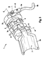
- FIG. 3 shows the hose pump 1 according to the embodiment in an enlarged perspective view in the open state.
- the exemplary embodiment has two coaxially arranged pump bodies 3, 3a in the main body 2b.
- the supply of the liquid to the two pump bodies 3, 3a via a in FIG. 4 illustrated branch hose 10, which has a double tube section 11.
- the two-fold hose section 11 branches at branches 14 and 15 from the simple portion of the hose 6, so that in both branches of the double hose section 11 identical volume flows are promoted during operation of the peristaltic pump.
Landscapes
- Engineering & Computer Science (AREA)
- Mechanical Engineering (AREA)
- General Engineering & Computer Science (AREA)
- Reciprocating Pumps (AREA)
- Details Of Reciprocating Pumps (AREA)
Description
- Die vorliegende Erfindung betrifft eine Schlauchpumpe, die zur Förderung von Flüssigkeiten, insbesondere bei Abfüllprozessen in einem Isolator, eingesetzt wird, bei dem eine Bedienung von außen erfolgen muss, sowie einen Isolator mit einer derartigen Schlauchpumpe.
- Bei in Isolatorabfüllmaschinen verwendeten Schlauchpumpen müssen die Installations- und Bedienschritte der darin angeordneten Schlauchpumpen durch Handschuheingriffe mit einer dadurch bedingten eingeschränkten Beweglichkeit und Fingerfertigkeit erfolgen. Bei den bisher verwendeten Schlauchpumpen ist jedoch eine Einhandbedienung, wie z. B. zur Installation und zum Austausch von Schläuchen und Anschlüssen, nicht möglich und bei der Verwendung von losen Bauteilen das Risiko des Herunterfallens solcher Teile im Isolator gegeben. Dies hätte eine Vergrößerung der Rüstzeit und schlimmstenfalls einen Stillstand der laufenden Abfüllprozesse zur Folge, wenn das das heruntergefallene Bauteil nur durch Öffnen des Isolators wieder erreicht werden kann.
-
EP 1 898 094 A2 offenbart eine Schlauchpumpe gemäß dem Oberbegriff des Anspruchs 1 mit einem Pumpenkörper, wobei für verschiedene Flüssigkeiten unterschiedliche Rollen des Pumpenkörpers und unterschiedliche Pumpgeschwindigkeiten vorgesehen werden. -
WO 2005/088130 A1 zeigt eine Vorrichtung für eine Schlauchpumpe, bei der eine Haltekonstruktion derart bewegbar ist, dass ein Pumpenkörper zwischen einer geöffneten und einer geschlossenen Position variieren kann. -
JP 61 055184 U -
EP 1 978 256 A1 zeigt eine Verriegelungsvorrichtung für einen Pumpenkörper einer Schlauchpumpe, die das zufällige Öffnen derselben verhindern soll. - Die erfindungsgemäße Schlauchpumpe mit den Merkmalen des Anspruchs 1 weist demgegenüber den Vorteil auf, dass hierbei die Bedien- bzw. Handhabungsschritte an den zu bewegenden Bauteilen der Schlauchpumpe, dem Deckel und der Verriegelungsvorrichtung, mit dem Handschuheingriff in den Isolator einhändig ausführbar sind. Ferner sind der Deckel und die Verriegelungsvorrichtung der Schlauchpumpe beweglich und unverlierbar am Gehäuse befestigt, sodass ein Herunterfallen dieser Teile im Isolator ausgeschlossen ist. Durch ihre entsprechend große Dimensionierung und Formgebung sind diese Teile über den/die verwendeten Handschuheingriff/e leicht zu greifen und zu betätigen.
- Die Schlauchpumpe weist zwei koaxial angeordnete Pumpenkörper im Gehäuse auf. Hierdurch kann eine im Vergleich zum einzelnen Pumpenkörper gleichmäßigere Flüssigkeitsförderung realisiert werden. Ferner erfolgt die Zuführung der Flüssigkeit zu den zwei Pumpenkörpern über einen Abzweigschlauch mit einem zweifachen Schlauchabschnitt. Hierdurch erfolgt eine gleichmäßige und kostengünstige Verteilung des Volumenstroms der Flüssigkeit auf beide Pumpenkörper und die Pumpenkörper können mit einem gemeinsamen Antrieb angetrieben werden.
- Die Unteransprüche zeigen bevorzugte Weiterbildungen der Erfindung.
- Weiterhin bevorzugt ist der Deckel der erfindungsgemäßen Schlauchpumpe um eine erste Achse schwenkbar am Gehäuse befestigt. Hierdurch kann der Deckel des Gehäuses einfach und für das Einlegen des Schlauchs nicht behindernd geöffnet werden. Zudem ist vorzugsweise die Verriegelungsvorrichtung der erfindungsgemäßen Schlauchpumpe um eine zweite Achse schwenkbar am Gehäuse befestigt, wodurch eine kompakte und funktionssichere Ent- bzw. Verriegelung des Deckels gewährleistet ist.
- Vorzugsweise ist das Gehäuse zylindrisch ausgeführt und der Deckel gibt im geöffneten Zustand einen Umfangsbereich von im Wesentlichen 180° des darin befindlichen Pumpenkörpers frei. Hierdurch wird das einhändige Einlegen des Schlauchs auf den Pumpenkörper wesentlich erleichtert.
- Weiterhin bevorzugt sind am Gehäuse zwei nach außen vorstehende Befestigungselemente, insbesondere Stifte, angeordnet, um den Abzweigschlauch jeweils an Verzweigungen an den Befestigungselementen einzuspannen. Hierdurch kann der Abzweigschlauch auf einfache Weise einhändig montiert und wieder demontiert werden und weist im Betrieb einen sicheren Sitz auf.
- Gemäß einer weiteren bevorzugten Ausgestaltung der Erfindung umfasst die Verriegelungsvorrichtung einen schwenkbaren Hebel, der in Längsrichtung gebogen ist und bezüglich des Gehäuses einen nach außen gekröpften Endbereich aufweist. Diese Formgebung erleichtert das Schwenken und Ver-bzw. Entriegeln des Deckels unter Verwendung des Handschuhs bei Einhandbedienung.
- Vorzugsweise ist die zweite Achse zum Schwenken der Verriegelungsvorrichtung senkrecht zur ersten Achse zum Öffnen des Deckels angeordnet. Hierdurch ist eine maximale resultierende Verriegelungskraft zwischen Deckel und Verriegelungsvorrichtung realisierbar.
- Weiterhin bevorzugt sind am Umfang des Pumpenkörpers drei Rollen im Abstand von 120° angeordnet. Hierdurch wird eine ausreichende Förderleistung mit einer minimalen Anzahl an Bauteilen und reduzierten Kosten erreicht.
- Ferner betrifft die Erfindung einen Isolator mit einer erfindungsgemäßen Schlauchpumpe, insbesondere zur Abfüllung von Arzneimitteln oder anderen toxischen Stoffen.
- Vorzugsweise kann der zusammen mit der erfindungsgemäßen Schlauchpumpe eingesetzte Isolator lediglich genau einen Handschuheingriff aufweisen. Hierdurch können ein vereinfachter Aufbau sowie eine Reduzierung der Herstellkosten des Isolators erreicht werden.
- Es sei angemerkt, dass mit der erfindungsgemäßen Schlauchpumpe grundsätzlich ein- oder mehrphasige Flüssigkeiten, Gemische aus Flüssigkeiten und Gasen, Gemische aus Flüssigkeiten und Feststoffen sowie pastöse Flüssigkeiten gefördert werden können, die im Wesentlichen einen Viskositätsbereich wie bei herkömmlich verwendeten Schlauchpumpen aufweisen.
- Nachfolgend wird das Ausführungsbeispiel der Erfindung unter Bezugnahme auf die begleitende Zeichnung im Detail beschrieben. In der Zeichnung ist:
- Figur 1
- eine vergrößerte perspektivische Darstellung eines Beispiels einer Schlauchpumpe;
- Figur 2
- eine vergrößerte perspektivische Darstellung der Schlauchpumpe von
Fig. 1 in geöffnetem Zustand; - Figur 3
- eine vergrößerte perspektivische Darstellung eines Ausführungsbeispiels der erfindungsgemäßen Schlauchpumpe; und
- Figur 4
- eine schematische Darstellung des in der Schlauchpumpe von
Fig. 3 verwendeten Abzweigschlauchs. - Nachfolgend wird unter Bezugnahme auf die
Figuren 1 und 2 eine Schlauchpumpe gemäß einem Beispiel im Detail beschrieben. - Wie aus der vergrößerten perspektivischen Ansicht eines Beispiels der Schlauchpumpe 1 von
Figur 1 ersichtlich, umfasst die Schlauchpumpe ein zylindrisches Gehäuse 2 mit einem Grundkörper 2b und einem Deckel 2a zum Öffnen des Gehäuses. - Zum Ent- bzw. Verriegeln des Deckels 2a, der um eine erste Achse A schwenkbar ist, ist eine Verriegelungsvorrichtung 5 am Gehäuse 2 angeordnet. Die Verriegelungsvorrichtung 5, die in
Figur 1 in verriegelter Stellung und inFigur 2 in entriegelter Stellung zu sehen ist, ist relativ zum Grundkörper 2b des Gehäuses 2 beweglich und am Grundkörper 2b unverlierbar befestigt. Die Verriegelungsvorrichtung 5 weist einen um eine zweite Achse B schwenkbaren Hebel 5a auf, der bei dem inFigur 1 dargestellten geschlossenen Zustand der Schlauchpumpe parallel zu einer dritten Achse C in Längsrichtung des Gehäuses 2 verläuft, gebogen ausgebildet ist und in Bezug auf das Gehäuse 2 einen nach außen gekröpften Endbereich 5b umfasst. Durch diese Formgebung des Hebels 5a wird das Ergreifen und Betätigen der Verriegelungsvorrichtung 5, insbesondere durch den bei Isolatorabfüllmaschinen erforderlichen Handschuheingriff, außerordentlich erleichtert und ist mit einer Hand ausführbar. - Gleichermaßen ist der Deckel 2a, wie aus
Figur 2 ersichtlich, relativ zum Grundkörper 2b des Gehäuses 2 beweglich sowie am Grundkörper 2b unverlierbar befestigt und kann somit einhändig um die erste Achse A geschwenkt werden. - Wie aus der perspektivischen Darstellung der in
Figur 2 im geöffneten Zustand gezeigten Schlauchpumpe ersichtlich, ist im Inneren des Grundkörpers 2b des Gehäuses 2 ferner ein um die dritte Achse C drehbarer Pumpenkörper 3 zum Fördern einer Flüssigkeit angeordnet. Dieser Pumpenkörper 3 weist eine Vielzahl von am seinem Umfang angeordneten Rollen 4 auf, auf die ein Schlauch 6 ohne eine erforderliche Fixierung aufgelegt wird. Wenn der um die erste Achse A schwenkbar befestigte Deckel 2a geschlossen und durch Schwenken der Verriegelungsvorrichtung 5 in Richtung eines Pfeils P verriegelt wird, drückt die Innenoberfläche 7 des Deckels 2a den Schlauch 6 auf die Rollen 4. Bei rotierendem Pumpenkörper 3 klemmen die umlaufenden Rollen 4 somit den Schlauch 6 abschnittsweise ab und fördern dadurch die Flüssigkeit. Beim Entriegeln des Deckels 2a durch Schwenken der Verriegelungsvorrichtung 5 entgegen der Richtung des Pfeils P wird der Deckel 2a durch den noch vorhandenen Flüssigkeitsdruck im Schlauch 6 nach außen gedrückt und kann im günstigsten Fall vollständig um die erste Achse A nach außen bis zu einer Position schwenken, wie sie inFigur 2 dargestellt ist. Aufgrund des am Grundkörper 2b unverlierbar befestigten Deckels 2a und der am Grundkörper 2b unverlierbar befestigten Verriegelungsvorrichtung 5 weist die erfindungsgemäße Schlauchpumpe vorteilhafterweise keine losen Bauteile auf, die im Inneren des Isolators herabfallen können. Vorzugsweise ist die zweite Achse B zum Schwenken der Verriegelungsvorrichtung 5 senkrecht zur dritten Achse C der Schlauchpumpe angeordnet und die erste Achse A zum Schwenken des Deckels 2a wiederum senkrecht zur zweiten Achse B der Verriegelungsvorrichtung 5 angeordnet, um einen kompakten und leicht montierbaren Aufbau der Schlauchpumpe zu erreichen. - In den
Figuren 3 und4 wird nun im Folgenden eine Schlauchpumpe 1 gemäß einem Ausführungsbeispiel der vorliegenden Erfindung beschrieben. Gleiche bzw. funktional gleiche Bauteile sind hier mit denselben Bezugszeichen wie im obigen Beispiel beschrieben. -
Figur 3 zeigt die Schlauchpumpe 1 gemäß dem Ausführungsbeispiel in vergrößerter perspektivischer Darstellung im geöffneten Zustand. Im Gegensatz zum in denFiguren 1 und 2 gezeigten Beispiel weist das Ausführungsbeispiel zwei koaxial angeordnete Pumpenkörper 3, 3a im Grundkörper 2b auf. Die Zuführung der Flüssigkeit zu den zwei Pumpenkörpern 3, 3a erfolgt über einen inFigur 4 dargestellten Abzweigschlauch 10, der einen zweifachen Schlauchabschnitt 11 aufweist. Wie inFigur 4 dargestellt, verzweigt sich der zweifache Schlauchabschnitt 11 jeweils an Verzweigungen 14 und 15 vom einfachen Abschnitt des Schlauchs 6, so dass in beiden Zweigen des zweifachen Schlauchabschnitts 11 beim Betrieb der Schlauchpumpe identische Volumenströme gefördert werden. - An der Außenseite des Grundkörpers 2b des Gehäuses 2 sind, wie in
Figur 3 ersichtlich, zwei vom Grundkörper 2b vorstehende Stifte 9 angeordnet. An einem dieser Stifte 9 wird der Schlauch 6 an seiner ersten Verzweigung 14 eingehängt und danach wird der zweifache Schlauchabschnitt 11 über die Pumpenkörper 3, 3a gezogen und der Schlauch 6 an seiner zweiten Verzweigung 15 am anderen Stift 9 eingehängt bzw. eingespannt. Dieser Vorgang ist mit dem verwendeten Handschuh, ebenso wie beim einfachen Schlauch des obigen Beispiels, auf einfache Weise einhändig durchführbar und weist folglich einen deutlichen Vorteil gegenüber der Schlauchmontage bei den derzeit verwendeten herkömmlichen Schlauchpumpen in einem Isolator auf, die im Handschuheingriff mit beiden Händen erfolgen muss. Ansonsten entspricht dieses Ausführungsbeispiel dem obigen Beispiel, sodass auf die dort gegebene Beschreibung verwiesen werden kann.
Claims (10)
- Schlauchpumpe, umfassend:ein Gehäuse (2) mit einem Grundkörper (2b) und einem Deckel (2a) zum Öffnen des Gehäuses;einen Pumpenkörper (3) zur Förderung einer Flüssigkeit, der im Innern des Grundkörpers (2b) des Gehäuses (2) um eine Achse (C) drehbar angeordnet ist; undeine Verriegelungsvorrichtung (5), welche am Gehäuse (2) angeordnet ist, um den Deckel (2a) freizugeben und zu verriegeln,wobei der Pumpenkörper (3) eine Vielzahl von am Umfang des Pumpenkörpers (3) angeordnete Rollen (4) aufweist, die eine in einem Schlauch (6) befindliche Flüssigkeit durch Rotieren des Pumpenkörpers (3) fördern, wobei die Rollen (4) den Schlauch (6) gegen eine Innenoberfläche (7) des Deckels (2a) abklemmen;wobei die Verriegelungsvorrichtung (5) relativ zum Grundkörper (2b) des Gehäuses (2) beweglich und am Grundkörper (2b) unverlierbar befestigt ist und einhändig betätigbar ist, undwobei der Deckel (2a) relativ zum Grundkörper (2b) des Gehäuses (2) beweglich und am Grundkörper (2b) unverlierbar befestigt ist und einhändig betätigbar ist, dadurch gekennzeichnet, dassdie Schlauchpumpe zwei koaxial angeordnete Pumpenkörper (3, 3a) im Gehäuse (2) aufweist, unddie Zuführung der Flüssigkeit zu den zwei Pumpenkörpern (3, 3a) über einen Abzweigschlauch (10) mit einem zweifachen Schlauchabschnitt (11) erfolgt.
- Schlauchpumpe nach Anspruch 1, wobei der Deckel (2a) um eine Achse (A) schwenkbar am Gehäuse (2) befestigt angeordnet ist.
- Schlauchpumpe nach Anspruch 1 oder 2, wobei die Verriegelungsvorrichtung (5) um eine Achse (B) schwenkbar am Gehäuse (2) befestigt angeordnet ist.
- Schlauchpumpe nach einem der vorhergehenden Ansprüche, dadurch gekennzeichnet, dass das Gehäuse (2) zylindrisch ausgebildet ist und der Deckel (2a) im geöffneten Zustand einen Umfangsbereich von im Wesentlichen 180° des Grundkörpers (2b) des Gehäuses (2) und des darin befindlichen Pumpenkörpers (3) freigibt.
- Schlauchpumpe nach Anspruch 1, dadurch gekennzeichnet, dass am Gehäuse (2) ferner zwei nach außen vorstehende Befestigungselemente, insbesondere Stifte (9), angeordnet sind, um den Abzweigschlauch (10) jeweils an Verzweigungen (14, 15) an den Befestigungselementen einhändig einzuspannen.
- Schlauchpumpe nach Anspruch 1 oder 5, dadurch gekennzeichnet, dass die Verriegelungsvorrichtung (5) einen schwenkbaren Hebel (5a) umfasst, wobei der Hebel (5a) in Längsrichtung gebogen ist und in Bezug auf das Gehäuse (2) einen nach außen gekröpften Endbereich (5b) aufweist.
- Schlauchpumpe nach einem der Ansprüche 3 bis 6, dadurch gekennzeichnet, dass die Achse (B) zum Schwenken der Verriegelungsvorrichtung (5) senkrecht zur Achse (A) zum Öffnen des Deckels (2a) angeordnet ist.
- Schlauchpumpe nach einem der vorhergehenden Ansprüche, dadurch gekennzeichnet, dass am Umfang des Pumpenkörpers (3) drei Rollen (4) im Abstand von jeweils 120° angeordnet sind.
- Isolator, umfassend eine Schlauchpumpe nach einem der vorhergehenden Ansprüche.
- Isolator nach Anspruch 9, umfassend genau einen Handschuheingriff.
Applications Claiming Priority (2)
| Application Number | Priority Date | Filing Date | Title |
|---|---|---|---|
| DE102009000299A DE102009000299A1 (de) | 2009-01-19 | 2009-01-19 | Schlauchpumpe |
| PCT/EP2009/066285 WO2010081591A1 (de) | 2009-01-19 | 2009-12-03 | Schlauchpumpe |
Publications (2)
| Publication Number | Publication Date |
|---|---|
| EP2387669A1 EP2387669A1 (de) | 2011-11-23 |
| EP2387669B1 true EP2387669B1 (de) | 2012-09-05 |
Family
ID=41647198
Family Applications (1)
| Application Number | Title | Priority Date | Filing Date |
|---|---|---|---|
| EP09764805A Active EP2387669B1 (de) | 2009-01-19 | 2009-12-03 | Schlauchpumpe |
Country Status (6)
| Country | Link |
|---|---|
| US (1) | US8545196B2 (de) |
| EP (1) | EP2387669B1 (de) |
| JP (1) | JP5399516B2 (de) |
| CN (1) | CN102282372B (de) |
| DE (1) | DE102009000299A1 (de) |
| WO (1) | WO2010081591A1 (de) |
Families Citing this family (7)
| Publication number | Priority date | Publication date | Assignee | Title |
|---|---|---|---|---|
| CN104895779B (zh) * | 2015-06-09 | 2017-11-07 | 常州普瑞流体技术有限公司 | 一种不锈钢蠕动泵泵头 |
| KR102307015B1 (ko) * | 2016-12-14 | 2021-10-01 | 호우덴 토마쎈 컴프레셔스 비브이 | 왕복동식 압축기 실린더 내 밸브용 클랭핑 장치 |
| WO2020098965A1 (en) * | 2018-11-14 | 2020-05-22 | Husqvarna Ab | Fluid pump |
| US11773839B2 (en) * | 2020-03-02 | 2023-10-03 | Masterflex, Llc | Multi-roller peristaltic pump head |
| DE102020113267A1 (de) | 2020-05-15 | 2021-11-18 | Aesculap Ag | Medizinische Schlauchpumpe mit Stempelelementen und zugehörige Schlauchanordnung |
| EP3981989A1 (de) * | 2020-10-07 | 2022-04-13 | Husqvarna Ab | Mechanismus für pumpe |
| CN116771650A (zh) * | 2023-05-08 | 2023-09-19 | 东富龙科技集团股份有限公司 | 一种对软管无磨损的恒流泵 |
Family Cites Families (24)
| Publication number | Priority date | Publication date | Assignee | Title |
|---|---|---|---|---|
| US3723030A (en) * | 1971-03-03 | 1973-03-27 | Buchler Instr Division | Peristaltic pump with stacked components |
| GB1417146A (en) * | 1972-08-09 | 1975-12-10 | Rank Organisation Ltd | Peristaltic pumps |
| JPS4970501U (de) * | 1972-10-03 | 1974-06-19 | ||
| JPS4970501A (de) | 1972-11-10 | 1974-07-08 | ||
| US4233001A (en) * | 1979-02-28 | 1980-11-11 | Peerless Electronics Research Corporation | Peristaltic pump |
| JPS6155184A (ja) | 1984-08-27 | 1986-03-19 | Canon Inc | El素子 |
| JPS6155184U (de) * | 1984-09-14 | 1986-04-14 | ||
| US4798580A (en) * | 1987-04-27 | 1989-01-17 | Site Microsurgical Systems, Inc. | Disposable peristaltic pump cassette system |
| US4886431A (en) * | 1988-04-29 | 1989-12-12 | Cole-Parmer Instrument Company | Peristaltic pump having independently adjustable cartridges |
| US4997347A (en) | 1990-01-12 | 1991-03-05 | Autotrol Corporation | Peristaltic motor |
| JPH0617021Y2 (ja) * | 1990-04-24 | 1994-05-02 | 康克 井野内 | スクイーズポンプ |
| JPH046583A (ja) | 1990-04-24 | 1992-01-10 | Mitsubishi Materials Corp | 操作盤の取り扱い説明装置 |
| US5443451A (en) * | 1993-11-17 | 1995-08-22 | Baxter International Inc. | Peristaltic pumping assembly |
| NL9500442A (nl) | 1995-03-06 | 1996-10-01 | Elu Ijmond Techniek B V | Slangepomp. |
| JPH1033663A (ja) * | 1996-07-25 | 1998-02-10 | Kanegafuchi Chem Ind Co Ltd | チューブ式ローラポンプ |
| US6041709A (en) * | 1998-11-12 | 2000-03-28 | Usadvantage, Inc. | Peristaltic pump for pumping ink or cleaning fluids in a printing machine |
| JP4034901B2 (ja) * | 1999-02-05 | 2008-01-16 | 株式会社アクアテック | チューブポンプ |
| US20060048844A1 (en) | 2002-10-23 | 2006-03-09 | William Merrill | Systems, devices and methods for aseptic processing |
| DE20218375U1 (de) | 2002-11-27 | 2003-10-16 | Lang Apparatebau Gmbh, 83313 Siegsdorf | Quetschrollenrotor für eine Schlauchpumpe |
| US7223079B2 (en) | 2003-07-28 | 2007-05-29 | The Coca-Cola Company | Quick loading peristaltic pump |
| CA2557915A1 (en) * | 2004-03-04 | 2005-03-22 | Cole-Parmer Instrument Company | Peristaltic pump |
| JP4929735B2 (ja) | 2006-01-26 | 2012-05-09 | 株式会社ジェイ・エム・エス | ローラポンプ |
| JP4970501B2 (ja) | 2009-07-06 | 2012-07-11 | 任天堂株式会社 | ゲームシステムおよびゲームプログラム |
| WO2011072039A1 (en) * | 2009-12-08 | 2011-06-16 | The Trustees Of Columbia University In The City Of New York | Peristaltic pump devices, methods, and systems |
-
2009
- 2009-01-19 DE DE102009000299A patent/DE102009000299A1/de not_active Withdrawn
- 2009-12-03 US US13/143,245 patent/US8545196B2/en not_active Expired - Fee Related
- 2009-12-03 JP JP2011545650A patent/JP5399516B2/ja active Active
- 2009-12-03 EP EP09764805A patent/EP2387669B1/de active Active
- 2009-12-03 WO PCT/EP2009/066285 patent/WO2010081591A1/de not_active Ceased
- 2009-12-03 CN CN200980154974.2A patent/CN102282372B/zh active Active
Also Published As
| Publication number | Publication date |
|---|---|
| CN102282372A (zh) | 2011-12-14 |
| DE102009000299A1 (de) | 2010-07-22 |
| JP2012515292A (ja) | 2012-07-05 |
| US20110274562A1 (en) | 2011-11-10 |
| JP5399516B2 (ja) | 2014-01-29 |
| WO2010081591A1 (de) | 2010-07-22 |
| EP2387669A1 (de) | 2011-11-23 |
| CN102282372B (zh) | 2014-08-13 |
| US8545196B2 (en) | 2013-10-01 |
Similar Documents
| Publication | Publication Date | Title |
|---|---|---|
| DE69103862T2 (de) | Infusionspumpe. | |
| EP2313022B1 (de) | Anschlussstück für austragvorrichtung | |
| DE69308366T2 (de) | Strömungsventil | |
| WO2010081591A1 (de) | Schlauchpumpe | |
| DE68917789T2 (de) | Deckel mit regelbarer Ausgiesstülle und Belüftungseinrichtung. | |
| EP2682604B1 (de) | Schlauchrollenpumpe mit einem auto-orientierbaren und -verriegelbaren Rotor sowie medizinisches Gerät zur extrakorporalen Blutbehandlung mit Schlauchrollenpumpe | |
| EP2682606B1 (de) | Multikonnektor und medizinisches Gerät zur extrakorporalen Blutbehandlung | |
| EP3246059B1 (de) | Durchflussregeleinrichtung für eine schlauchleitung eines medizinischen infusionssystems | |
| DE102011004035A1 (de) | Pulverpumpe zum Fördern von Beschichtungspulver | |
| DE102012105614A1 (de) | Deckelvorrichtung zur schwenkbaren Halterung eines Deckels an einem medizinischen Gerät zur extrakorporalen Blutbehandlung; medizinisches Gerät zur extrakorporalen Blutbehandlung mit Deckelvorrichtung | |
| EP4414312B1 (de) | Schlauchheber | |
| EP3354619A1 (de) | Entnahmesystem | |
| EP4136353B1 (de) | Peristaltikpumpe für eine vorrichtung zur extrakorporalen blutbehandlung | |
| EP2737939A2 (de) | Mischbehälter | |
| DE3204652C2 (de) | ||
| DE2558304B2 (de) | Mischkopf für reaktionsfähige, flüssige Komponenten | |
| DE102006061101A1 (de) | Korbführungsschiene für eine Geschirrspülmaschine | |
| EP1760024B1 (de) | Tragbare Schlauch- oder Kabeltrommel | |
| DE1556591A1 (de) | Lademaschine mit nach beiden Seiten kippbarer Ladeschaufel | |
| DE19742684C2 (de) | Abstreifvorrichtung | |
| EP1656064A1 (de) | Staubsauger mit einem schwenkgriff | |
| DE3724886C1 (de) | Vorrichtung zum Verbinden eines Schlauchendes mit einem Anschlussstutzen | |
| WO2001076840A1 (de) | Spritzvorrichtung zum herstellen eines mörtels mit sicherheits-einrichtung | |
| EP3124179A1 (de) | Handmontagewerkzeug für einen motorflansch und system mit einem handmontagewerkzeug | |
| EP4279182B1 (de) | Pipette für den gebrauch mit einer pipettenspitze |
Legal Events
| Date | Code | Title | Description |
|---|---|---|---|
| PUAI | Public reference made under article 153(3) epc to a published international application that has entered the european phase |
Free format text: ORIGINAL CODE: 0009012 |
|
| 17P | Request for examination filed |
Effective date: 20110819 |
|
| AK | Designated contracting states |
Kind code of ref document: A1 Designated state(s): AT BE BG CH CY CZ DE DK EE ES FI FR GB GR HR HU IE IS IT LI LT LU LV MC MK MT NL NO PL PT RO SE SI SK SM TR |
|
| DAX | Request for extension of the european patent (deleted) | ||
| GRAP | Despatch of communication of intention to grant a patent |
Free format text: ORIGINAL CODE: EPIDOSNIGR1 |
|
| GRAS | Grant fee paid |
Free format text: ORIGINAL CODE: EPIDOSNIGR3 |
|
| GRAA | (expected) grant |
Free format text: ORIGINAL CODE: 0009210 |
|
| AK | Designated contracting states |
Kind code of ref document: B1 Designated state(s): AT BE BG CH CY CZ DE DK EE ES FI FR GB GR HR HU IE IS IT LI LT LU LV MC MK MT NL NO PL PT RO SE SI SK SM TR |
|
| REG | Reference to a national code |
Ref country code: GB Ref legal event code: FG4D Free format text: NOT ENGLISH |
|
| REG | Reference to a national code |
Ref country code: CH Ref legal event code: EP |
|
| REG | Reference to a national code |
Ref country code: AT Ref legal event code: REF Ref document number: 574255 Country of ref document: AT Kind code of ref document: T Effective date: 20120915 |
|
| REG | Reference to a national code |
Ref country code: IE Ref legal event code: FG4D Free format text: LANGUAGE OF EP DOCUMENT: GERMAN |
|
| REG | Reference to a national code |
Ref country code: DE Ref legal event code: R096 Ref document number: 502009004645 Country of ref document: DE Effective date: 20121031 |
|
| REG | Reference to a national code |
Ref country code: NL Ref legal event code: VDEP Effective date: 20120905 |
|
| PG25 | Lapsed in a contracting state [announced via postgrant information from national office to epo] |
Ref country code: HR Free format text: LAPSE BECAUSE OF FAILURE TO SUBMIT A TRANSLATION OF THE DESCRIPTION OR TO PAY THE FEE WITHIN THE PRESCRIBED TIME-LIMIT Effective date: 20120905 Ref country code: NO Free format text: LAPSE BECAUSE OF FAILURE TO SUBMIT A TRANSLATION OF THE DESCRIPTION OR TO PAY THE FEE WITHIN THE PRESCRIBED TIME-LIMIT Effective date: 20121205 Ref country code: FI Free format text: LAPSE BECAUSE OF FAILURE TO SUBMIT A TRANSLATION OF THE DESCRIPTION OR TO PAY THE FEE WITHIN THE PRESCRIBED TIME-LIMIT Effective date: 20120905 Ref country code: LT Free format text: LAPSE BECAUSE OF FAILURE TO SUBMIT A TRANSLATION OF THE DESCRIPTION OR TO PAY THE FEE WITHIN THE PRESCRIBED TIME-LIMIT Effective date: 20120905 |
|
| REG | Reference to a national code |
Ref country code: LT Ref legal event code: MG4D Effective date: 20120919 |
|
| PG25 | Lapsed in a contracting state [announced via postgrant information from national office to epo] |
Ref country code: LV Free format text: LAPSE BECAUSE OF FAILURE TO SUBMIT A TRANSLATION OF THE DESCRIPTION OR TO PAY THE FEE WITHIN THE PRESCRIBED TIME-LIMIT Effective date: 20120905 Ref country code: SI Free format text: LAPSE BECAUSE OF FAILURE TO SUBMIT A TRANSLATION OF THE DESCRIPTION OR TO PAY THE FEE WITHIN THE PRESCRIBED TIME-LIMIT Effective date: 20120905 Ref country code: GR Free format text: LAPSE BECAUSE OF FAILURE TO SUBMIT A TRANSLATION OF THE DESCRIPTION OR TO PAY THE FEE WITHIN THE PRESCRIBED TIME-LIMIT Effective date: 20121206 Ref country code: SE Free format text: LAPSE BECAUSE OF FAILURE TO SUBMIT A TRANSLATION OF THE DESCRIPTION OR TO PAY THE FEE WITHIN THE PRESCRIBED TIME-LIMIT Effective date: 20120905 |
|
| PG25 | Lapsed in a contracting state [announced via postgrant information from national office to epo] |
Ref country code: RO Free format text: LAPSE BECAUSE OF FAILURE TO SUBMIT A TRANSLATION OF THE DESCRIPTION OR TO PAY THE FEE WITHIN THE PRESCRIBED TIME-LIMIT Effective date: 20120905 Ref country code: EE Free format text: LAPSE BECAUSE OF FAILURE TO SUBMIT A TRANSLATION OF THE DESCRIPTION OR TO PAY THE FEE WITHIN THE PRESCRIBED TIME-LIMIT Effective date: 20120905 Ref country code: CZ Free format text: LAPSE BECAUSE OF FAILURE TO SUBMIT A TRANSLATION OF THE DESCRIPTION OR TO PAY THE FEE WITHIN THE PRESCRIBED TIME-LIMIT Effective date: 20120905 Ref country code: NL Free format text: LAPSE BECAUSE OF FAILURE TO SUBMIT A TRANSLATION OF THE DESCRIPTION OR TO PAY THE FEE WITHIN THE PRESCRIBED TIME-LIMIT Effective date: 20120905 Ref country code: IS Free format text: LAPSE BECAUSE OF FAILURE TO SUBMIT A TRANSLATION OF THE DESCRIPTION OR TO PAY THE FEE WITHIN THE PRESCRIBED TIME-LIMIT Effective date: 20130105 |
|
| PG25 | Lapsed in a contracting state [announced via postgrant information from national office to epo] |
Ref country code: SK Free format text: LAPSE BECAUSE OF FAILURE TO SUBMIT A TRANSLATION OF THE DESCRIPTION OR TO PAY THE FEE WITHIN THE PRESCRIBED TIME-LIMIT Effective date: 20120905 Ref country code: PT Free format text: LAPSE BECAUSE OF FAILURE TO SUBMIT A TRANSLATION OF THE DESCRIPTION OR TO PAY THE FEE WITHIN THE PRESCRIBED TIME-LIMIT Effective date: 20130107 Ref country code: PL Free format text: LAPSE BECAUSE OF FAILURE TO SUBMIT A TRANSLATION OF THE DESCRIPTION OR TO PAY THE FEE WITHIN THE PRESCRIBED TIME-LIMIT Effective date: 20120905 |
|
| BERE | Be: lapsed |
Owner name: ROBERT BOSCH G.M.B.H. Effective date: 20121231 |
|
| PLBE | No opposition filed within time limit |
Free format text: ORIGINAL CODE: 0009261 |
|
| STAA | Information on the status of an ep patent application or granted ep patent |
Free format text: STATUS: NO OPPOSITION FILED WITHIN TIME LIMIT |
|
| PG25 | Lapsed in a contracting state [announced via postgrant information from national office to epo] |
Ref country code: MC Free format text: LAPSE BECAUSE OF NON-PAYMENT OF DUE FEES Effective date: 20121231 Ref country code: DK Free format text: LAPSE BECAUSE OF FAILURE TO SUBMIT A TRANSLATION OF THE DESCRIPTION OR TO PAY THE FEE WITHIN THE PRESCRIBED TIME-LIMIT Effective date: 20120905 Ref country code: BG Free format text: LAPSE BECAUSE OF FAILURE TO SUBMIT A TRANSLATION OF THE DESCRIPTION OR TO PAY THE FEE WITHIN THE PRESCRIBED TIME-LIMIT Effective date: 20121205 |
|
| 26N | No opposition filed |
Effective date: 20130606 |
|
| REG | Reference to a national code |
Ref country code: IE Ref legal event code: MM4A |
|
| PG25 | Lapsed in a contracting state [announced via postgrant information from national office to epo] |
Ref country code: BE Free format text: LAPSE BECAUSE OF NON-PAYMENT OF DUE FEES Effective date: 20121231 |
|
| REG | Reference to a national code |
Ref country code: DE Ref legal event code: R097 Ref document number: 502009004645 Country of ref document: DE Effective date: 20130606 |
|
| PG25 | Lapsed in a contracting state [announced via postgrant information from national office to epo] |
Ref country code: ES Free format text: LAPSE BECAUSE OF FAILURE TO SUBMIT A TRANSLATION OF THE DESCRIPTION OR TO PAY THE FEE WITHIN THE PRESCRIBED TIME-LIMIT Effective date: 20121216 Ref country code: IE Free format text: LAPSE BECAUSE OF NON-PAYMENT OF DUE FEES Effective date: 20121203 |
|
| PG25 | Lapsed in a contracting state [announced via postgrant information from national office to epo] |
Ref country code: CY Free format text: LAPSE BECAUSE OF FAILURE TO SUBMIT A TRANSLATION OF THE DESCRIPTION OR TO PAY THE FEE WITHIN THE PRESCRIBED TIME-LIMIT Effective date: 20120905 Ref country code: MT Free format text: LAPSE BECAUSE OF FAILURE TO SUBMIT A TRANSLATION OF THE DESCRIPTION OR TO PAY THE FEE WITHIN THE PRESCRIBED TIME-LIMIT Effective date: 20120905 |
|
| PG25 | Lapsed in a contracting state [announced via postgrant information from national office to epo] |
Ref country code: TR Free format text: LAPSE BECAUSE OF FAILURE TO SUBMIT A TRANSLATION OF THE DESCRIPTION OR TO PAY THE FEE WITHIN THE PRESCRIBED TIME-LIMIT Effective date: 20120905 |
|
| PG25 | Lapsed in a contracting state [announced via postgrant information from national office to epo] |
Ref country code: SM Free format text: LAPSE BECAUSE OF FAILURE TO SUBMIT A TRANSLATION OF THE DESCRIPTION OR TO PAY THE FEE WITHIN THE PRESCRIBED TIME-LIMIT Effective date: 20120905 Ref country code: LU Free format text: LAPSE BECAUSE OF NON-PAYMENT OF DUE FEES Effective date: 20121203 |
|
| PG25 | Lapsed in a contracting state [announced via postgrant information from national office to epo] |
Ref country code: HU Free format text: LAPSE BECAUSE OF FAILURE TO SUBMIT A TRANSLATION OF THE DESCRIPTION OR TO PAY THE FEE WITHIN THE PRESCRIBED TIME-LIMIT Effective date: 20091203 |
|
| REG | Reference to a national code |
Ref country code: CH Ref legal event code: PL |
|
| GBPC | Gb: european patent ceased through non-payment of renewal fee |
Effective date: 20131203 |
|
| PG25 | Lapsed in a contracting state [announced via postgrant information from national office to epo] |
Ref country code: CH Free format text: LAPSE BECAUSE OF NON-PAYMENT OF DUE FEES Effective date: 20131231 Ref country code: LI Free format text: LAPSE BECAUSE OF NON-PAYMENT OF DUE FEES Effective date: 20131231 |
|
| PG25 | Lapsed in a contracting state [announced via postgrant information from national office to epo] |
Ref country code: GB Free format text: LAPSE BECAUSE OF NON-PAYMENT OF DUE FEES Effective date: 20131203 |
|
| PG25 | Lapsed in a contracting state [announced via postgrant information from national office to epo] |
Ref country code: MK Free format text: LAPSE BECAUSE OF FAILURE TO SUBMIT A TRANSLATION OF THE DESCRIPTION OR TO PAY THE FEE WITHIN THE PRESCRIBED TIME-LIMIT Effective date: 20120905 |
|
| REG | Reference to a national code |
Ref country code: FR Ref legal event code: PLFP Year of fee payment: 7 |
|
| REG | Reference to a national code |
Ref country code: AT Ref legal event code: MM01 Ref document number: 574255 Country of ref document: AT Kind code of ref document: T Effective date: 20141203 |
|
| PG25 | Lapsed in a contracting state [announced via postgrant information from national office to epo] |
Ref country code: AT Free format text: LAPSE BECAUSE OF NON-PAYMENT OF DUE FEES Effective date: 20141203 |
|
| REG | Reference to a national code |
Ref country code: FR Ref legal event code: PLFP Year of fee payment: 8 |
|
| REG | Reference to a national code |
Ref country code: FR Ref legal event code: PLFP Year of fee payment: 9 |
|
| REG | Reference to a national code |
Ref country code: DE Ref legal event code: R082 Ref document number: 502009004645 Country of ref document: DE Representative=s name: DREISS PATENTANWAELTE PARTG MBB, DE Ref country code: DE Ref legal event code: R081 Ref document number: 502009004645 Country of ref document: DE Owner name: SYNTEGON TECHNOLOGY GMBH, DE Free format text: FORMER OWNER: ROBERT BOSCH PACKAGING TECHNOLOGY GMBH, 71332 WAIBLINGEN, DE Ref country code: DE Ref legal event code: R081 Ref document number: 502009004645 Country of ref document: DE Owner name: SYNTEGON TECHNOLOGY GMBH, DE Free format text: FORMER OWNER: ROBERT BOSCH GMBH, 70469 STUTTGART, DE |
|
| REG | Reference to a national code |
Ref country code: DE Ref legal event code: R081 Ref document number: 502009004645 Country of ref document: DE Owner name: SYNTEGON TECHNOLOGY GMBH, DE Free format text: FORMER OWNER: SYNTEGON TECHNOLOGY GMBH, 71332 WAIBLINGEN, DE |
|
| PGFP | Annual fee paid to national office [announced via postgrant information from national office to epo] |
Ref country code: FR Payment date: 20251217 Year of fee payment: 17 |
|
| PGFP | Annual fee paid to national office [announced via postgrant information from national office to epo] |
Ref country code: DE Payment date: 20251222 Year of fee payment: 17 |
|
| PGFP | Annual fee paid to national office [announced via postgrant information from national office to epo] |
Ref country code: IT Payment date: 20251231 Year of fee payment: 17 |