EP2384839B1 - Dispositif de tension - Google Patents
Dispositif de tension Download PDFInfo
- Publication number
- EP2384839B1 EP2384839B1 EP10161837A EP10161837A EP2384839B1 EP 2384839 B1 EP2384839 B1 EP 2384839B1 EP 10161837 A EP10161837 A EP 10161837A EP 10161837 A EP10161837 A EP 10161837A EP 2384839 B1 EP2384839 B1 EP 2384839B1
- Authority
- EP
- European Patent Office
- Prior art keywords
- clamping device
- accordance
- sliding sleeve
- clamping
- servomotor
- Prior art date
- Legal status (The legal status is an assumption and is not a legal conclusion. Google has not performed a legal analysis and makes no representation as to the accuracy of the status listed.)
- Active
Links
Images


Classifications
-
- B—PERFORMING OPERATIONS; TRANSPORTING
- B23—MACHINE TOOLS; METAL-WORKING NOT OTHERWISE PROVIDED FOR
- B23B—TURNING; BORING
- B23B31/00—Chucks; Expansion mandrels; Adaptations thereof for remote control
- B23B31/02—Chucks
- B23B31/24—Chucks characterised by features relating primarily to remote control of the gripping means
- B23B31/28—Chucks characterised by features relating primarily to remote control of the gripping means using electric or magnetic means in the chuck
-
- Y—GENERAL TAGGING OF NEW TECHNOLOGICAL DEVELOPMENTS; GENERAL TAGGING OF CROSS-SECTIONAL TECHNOLOGIES SPANNING OVER SEVERAL SECTIONS OF THE IPC; TECHNICAL SUBJECTS COVERED BY FORMER USPC CROSS-REFERENCE ART COLLECTIONS [XRACs] AND DIGESTS
- Y10—TECHNICAL SUBJECTS COVERED BY FORMER USPC
- Y10T—TECHNICAL SUBJECTS COVERED BY FORMER US CLASSIFICATION
- Y10T279/00—Chucks or sockets
- Y10T279/21—Chucks or sockets with measuring, indicating or control means
-
- Y—GENERAL TAGGING OF NEW TECHNOLOGICAL DEVELOPMENTS; GENERAL TAGGING OF CROSS-SECTIONAL TECHNOLOGIES SPANNING OVER SEVERAL SECTIONS OF THE IPC; TECHNICAL SUBJECTS COVERED BY FORMER USPC CROSS-REFERENCE ART COLLECTIONS [XRACs] AND DIGESTS
- Y10—TECHNICAL SUBJECTS COVERED BY FORMER USPC
- Y10T—TECHNICAL SUBJECTS COVERED BY FORMER US CLASSIFICATION
- Y10T279/00—Chucks or sockets
- Y10T279/27—Separate chuck-actuating power source
Definitions
- the invention relates to a clamping device according to the preamble of claim 1, and a method according to the preamble of claim 21.
- a clamping device and such a method are made DE 3 727 445 C1 known.
- a clamping device in particular for machine tools, for example, provided with a power chuck for holding a workpiece and the clamping jaws are actuated by means of the clamping device via an axially adjustable tie rod, wherein the clamping device comprises a switchable electric servomotor for triggering clamping movements, a motion converter for implementing the Verstellzien Rotor shaft of the servomotor in the required for the actuation of the clamping jaws axial adjustment movements of the drawbar and a power storage for maintaining the clamping force, and a method for controlling the servo motor in response to the rotational speed of the drive motor of the machine tool are submitted.
- EP 0 228 007 A2 is a clamping device of this type is known.
- the rotor of the servo motor is in this case, as soon as this electrical energy is supplied, displaced axially against the force of a spring by the electromagnetic field built up between the stator and the spring in the middle position and connected via a toothing with a component, which via the interengaging threaded motion converter is coupled to the pull rod.
- the power storage consisting of several plate spring packets, as soon as the pull rod is no longer moved, activated by this component,
- the object of the invention is therefore to form a clamping device of the type mentioned in such a way that the servomotor must be put into operation only for clamping and relaxing a workpiece and thus is in drive connection only in these operating conditions with the clamping device.
- all components of the clamping device involved in the power transmission are to be fixedly connected to the machine spindle so that restoring movements of the power chuck can be ruled out.
- a clamping device of the aforementioned type in that the servomotor can be connected by means of a controlled adjustable sliding sleeve directly or via intermediate links with the motion converter that the motion converter and the energy storage can be coupled in one with the machine spindle of the machine tool Housing are used and that in the clamping position of the clamping device, the sliding sleeve of the servo motor decoupled and the housing is firmly connected via this with the motion converter.
- the housing of the clamping device in cross-section Z-shaped, which should consist of a machine spindle facing sleeve for receiving the motion converter and the energy accumulator and a servomotor facing hollow shaft for holding the sliding sleeve, wherein the sleeve and the hollow shaft of Housing should be firmly connected to each other via an intermediate wall.
- intermediate links for positive drive connection of the sliding sleeve with the motion converter which may each consist of a shaft provided with differently designed gears, on the one hand directly or connected via intermediate wheels with the sliding sleeve and on the other hand with the motion converter and designed as a reduction gear.
- the housing can also be formed cup-shaped by an axially projecting sleeve is formed on a connectable with the machine spindle plate-shaped ring, with a radial distance from the pull rod, in which the motion converter and the energy storage are to be used.
- the sliding sleeve should also be alternately positively coupled via two arranged respectively on the lateral end faces sprockets with a drive wheel connected to the servo motor and the housing or its intermediate wall attached to this sprockets.
- the teeth of the sprockets mounted in the drive wheel, the housing and the sliding sleeve should be arranged and spaced from each other so that cover the interlocking teeth until the respective end position of the sliding sleeve for an adjustment of the sliding sleeve.
- the sliding sleeve should be supported against the force of one or more compression springs on a mounted on the hollow shaft of the housing flange.
- a servo device for example in the form of an adjusting piston or an electromagnet inserted in a cylinder and adjustable by a pressure medium.
- the servo motor which can be coupled directly or via intermediate links to the drive wheel can be arranged in alignment, axially parallel or axially perpendicular to the longitudinal axis of the housing of the clamping device.
- the motion converter can be formed by a planetary roller arranged between a hollow shaft that can be connected to the servomotor and the pull rod, wherein the energy store can be arranged on the hollow shaft of the motion converter and activated by it.
- the energy accumulator should consist of a spring assembly inserted between two constant spaced and mutually braced bearings and two laterally next to each other this provided the rolling bearing cross-sleeves, at the mutually facing faces the spring assembly is applied.
- To activate the energy storage device it is appropriate to assign the sleeves provided on the housing stops, with which the sleeves interact with their outer end faces alternately.
- the spring package should in this case from several vzw used between the two bearings. Supported on the outer rings and distributed uniformly over the circumference arranged spacer bolts lined up or arranged next to these helical compression springs are preferably formed with rectangular cross-section or plate springs.
- the hollow shaft of the motion converter can be adjusted in each case against the adjustment of the pull rod to a preferably adjustable in both adjustment directions adjustment.
- the tensioning device with a displacement measuring device, which may consist of a directly attached to the pull rod or via intermediate links attached to this position indicator, for example in the form of a Abfrageringes, and a stationary sensor, the signals of a display unit are zuleitbar , wherein the position indicator of the path measuring device penetrate the housing of the clamping device and the sensor should be supported at the level of the position indicator on the machine tool.
- a displacement measuring device which may consist of a directly attached to the pull rod or via intermediate links attached to this position indicator, for example in the form of a Abfrageringes, and a stationary sensor
- the signals of a display unit are zuleitbar , wherein the position indicator of the path measuring device penetrate the housing of the clamping device and the sensor should be supported at the level of the position indicator on the machine tool.
- the drive motor of the machine tool via a control unit with the servo motor.
- a clamping device If a clamping device according to the invention is formed, it is impossible that the clamping force of the power chuck changed uncontrollably during a work process and that this is sometimes opened automatically. Characterized in that the servomotor is drivingly connected only for clamping and releasing a workpiece with the components involved in the power transmission, can be triggered by these only in these operating conditions adjustment movements. In one operation, however, the components involved in the transmission are coupled via the sliding sleeve with the machine spindle and therefore blocked. A change in position of the tie rod and thus a relaxation in the power chuck is not possible.
- the energy storage but ensures that the clamping force, even with a conditional by the machining of the workpiece reduction, is maintained.
- the motion converter namely the energy storage can be biased defined. For Nachschreiben is therefore stored in this energy available.
- a clamping device is thus created, which is not only relatively simple in their structural design and thus can be produced economically, but, above all, always safe use with low energy consumption, since the servo motor can be taken out of service during operation , guaranteed and versatile.
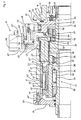
- FIGS. 1 and 5 illustrated and 1 and 1 'designated clamping device is used to operate a power tool chuck 5 arranged on a machine tool 2, by means of the radially adjustable clamping jaws 6 is a workpiece 10 to be machined in the power chuck 5 is clamped.
- the clamping jaws of the power chuck 5 are in this case via lever 8 by an axially adjustable, two-part pull rod 7, 7 'actuated, which is connected to a switchable electric servomotor 11 via a motion converter 31 and 31' in drive connection.
- the motion converter 31 or 31 ' rotational adjustment movements of the servo motor 11 are converted into axial feed movements of the pull rod 7, 7'.
- the servomotor 11 consists of an axially parallel to the longitudinal axis A of the clamping device 1 stationarily arranged stator 12 and a rotor 13, with the rotor shaft 14, a pinion 15 is rotatably connected, which engages in a mounted on a drive gear 16 teeth 17.
- the motion converter 31 is in the embodiment of the clamping device 1 after FIG. 1 used in a Z-shaped housing 21, which, like that of FIG. 5 can be seen by means of screws 9 'on a flange 9 by an electric motor 4 driven machine spindle 3 is fixed.
- the housing 21 in this case has a sleeve 22, an intermediate wall 23 connected thereto by means of screws 25 and a hollow shaft 24 integrally formed thereon.
- a cover 26 By a cover 26, the sleeve 22 is closed on the machine spindle 3 facing side.
- a flange 28 is attached by means of screws 29 to the hollow shaft 24 on which the drive unit 16 is rotatably supported by means of a bearing 30.
- the lid 26 is fixedly connected to the sleeve 22 by screws 26 '. By means of screws 27, which pass through the lid 26, the sleeve 22 and thus the housing 21 is fixed to the machine spindle 3.
- the housing 21 ' is cup-shaped in cross-section.
- an axially projecting sleeve 22 ' is here formed with a radial distance to the pull rod 7', into which the motion converter 31 'and the energy storage 41' are inserted.
- the motion converter 31 or 31 ' consists of a hollow shaft 32 which can be connected to the servomotor 11 and planetary rollers 33, which are inserted between the hollow shaft 32 and the pull rod 7 and engage via a thread 34 in an external thread 35 incorporated on the pull rod 7. Via a bearing 36 and a shoulder 36 ', which is supported in the cover 26, the hollow shaft 32 is held against rotation.
- the drive connection between the servomotor 11 associated drive unit 16 and the hollow shaft 32 of the motion converter 31 is accomplished via the sliding sleeve 51.
- the drive power is transmitted from the drive unit 16 via a gear ring 18 attached thereto and provided on the sliding sleeve 51 sprocket 52 on this.
- an intermediate gear 57 is driven by the sliding sleeve 51, which is drivingly connected via an external toothing 59 with the sliding sleeve 51.
- the intermediate gear 57 is in drive connection with a further external toothing 60 with a toothed wheel 39 which is worked on as an intermediate member 38 on a shaft 38 'rotatably mounted in the intermediate wall 23 by means of a roller bearing 38 Shaft 38 'mounted teeth 40 which engages in a provided on the hollow shaft 22 gear 37, the drive connection is accomplished.
- the sliding sleeve 41 is connected directly to the hollow shaft 32 of the motion converter 31.
- the energy storage device 41 or 41 ' has a spring set 42 inserted between two spaced-apart rolling bearings 43 and 44 and two angularly shaped sleeves 46 and 47.
- spring assembly 42 are a plurality of uniformly distributed over the circumference, between the sleeves 46 and 47 used and held on spacer bolts 45 helical compression springs 42 'or disc springs 42 "( FIG. 5 ), which are supported on the mutually facing end surfaces 46 'and 47' of the sleeves 46 and 47.
- the outer face 46 "and 47" of the sleeves 46 and 47 in contrast, cooperate with stops 48 and 49 provided on the housing 22.
- the inner rings of the bearings 43 and 44 are in this case by means of a nut screwed onto the hollow shaft 32 43 ', a sleeve inserted between the bearings 43 and 44 43 "and a protruding from the hollow shaft 33 stop 43"' braced against each other.
- a servo 61 which consists of a piston 62 inserted in a cylinder 62, acted upon by a pressure medium on both sides. Via an angle piece 68, which engages in a incorporated in the sliding sleeve 51 circumferential groove 56, the piston 63 is drivingly connected thereto.
- the piston 63 and with this the elbow 68 is moved to the right or left.
- the sliding sleeve 51 is taken, so that it is also moved to the right or left and provided at the end faces teeth 52 or 53 alternately in the attached to the drive gear 16 sprocket 18 or on the intermediate piece 23 or the sleeve 22nd 'Engaged sprocket 54 intervene.
- the sprockets 18, 52, 53 and 54 on the drive wheel 16 of the sliding sleeve 51 and the housing 21, should be spaced apart from each other be that during an adjusting movement of the sliding sleeve 41, the interlocking teeth cover up to the end position of the sliding sleeve 41.
- the drive connection between the sliding sleeve 51 and the housing 21, with the teeth of the sprockets 53 and 54, is secured, the sliding sleeve 51 is supported by a compression spring 55 on the flange 28.
- FIG. 1 shown illustration of the clamping device 1
- the sliding sleeve 51 by operating the servo 61 to move to the right, so that attached to the sliding sleeve 51 sprocket 52, as shown in FIG. 2 is shown, engages in the provided on the drive gear 16 sprocket 18. If the servomotor 11 is switched on in this operating state, the torque output by the latter is transmitted to the hollow shaft 32 of the motion converter 31 via the sliding sleeve 51, the intermediate wheel 57 and the intermediate element 38.
- the introduced rotational movement is converted into a translational movement and the pull rod 7, depending on the direction of rotation, moved to the left or right, so that the clamping jaws 6 of the power chuck 5 are pressed against the workpiece 10 from the inside or from the outside.
- the energy store 41 is activated.
- the voltage applied to the workpiece 10 jaws 6 form in this operating condition, as in FIG. 4 is shown schematically, as it were a stop, so that the pull rod 7 is stopped.
- the threaded lead screw 33 if the torque introduced by the servo motor 11 continues, the direction of movement is reversed, and the hollow shaft 32 is now moved to the right, assuming that the pull rod 7 was initially moved to the left
- a selectable adjustment X to the abutment of the end face 47 "of the sleeve 47 on the stop 49 of the housing 21, as the FIG. 4 can be seen.
- the energy storage 41 as soon as the clamping force is reduced by work-related changes to the workpiece 10, the stored energy in the spring assembly 42, so that a loss of clamping force is automatically compensated.
- the servo motor 11 can be separated from the motion converter 31.
- the sliding sleeve 51 by means of the servo 61 in the in FIG. 3 to move the position shown.
- the teeth of the ring gear 53 now engage in the teeth of the toothed ring 54 attached to the housing 21.
- the sliding sleeve 51 via the intermediate gear 57 and the intermediate member 58 with the hollow shaft 32 of the motion converter 31 is drivingly connected.
- the cooperating teeth of the drive wheel 16, the housing 21 and the sliding sleeve 51 are arranged such that during an adjustment of the sliding sleeve 51 the overlap interlocking teeth until taking the respective end position of the sliding sleeve 51.
- a support of the motion converter 31 is always given.
- the drive motor 4 of the machine tool 2 via a control unit 70 and connecting lines 70 'to the servo motor 11 is electrically connected.
- the speed of the servomotor 11 can be adjusted by means of the control unit 70 such that it rotates synchronously with the rotational speed of the drive motor 4 before the connection of the drive wheel 16 with the sliding sleeve 51. If the rotational speed of the servomotor 11 is increased or decreased relative to the rotational speed of the drive motor 4, the clamping force of the power chuck 5 is thus increased or reduced.
- the clamping device 1 ' In order to be able to monitor the operating state of the power chuck 5 during working operations, the clamping device 1 ', as shown in FIG. 5 is shown equipped with a displacement measuring device 71.
- a position indicator 72 in the form of an interrogation ring 73 is attached directly to the pull rod 7 'and engages through the housing 21' provided with a corresponding recess 22 "and belongs together with a sensor 74 arranged on a stationary wall 80 Bearings of the pull rod 7 'and thus also the clamping jaws 6 of the power chuck 5 detected signals are fed via a signal line 75 of a control and / or display unit and evaluated accordingly.
Claims (21)
- Dispositif de serrage (1) en particulier pour machines-outils (2), équipé p. ex. d'un mandrin de serrage motorisé (5) pour le serrage d'une pièce à usiner (10), dont les mors de serrage (6) se laissent actionner à l'aide du dispositif de serrage (1) par l'intermédiaire d'une tige de traction axialement réglable (7, 7'), le dispositif de serrage (1) comprenant un servomoteur électrique commutable (11) pour le déclenchement des mouvements de serrage, un convertisseur de mouvement (31) pour la conversion des mouvements de réglage de l'arbre de rotor (14) du servomoteur (11) en mouvements de réglage axiaux de la tige de traction (7, 7') nécessaires à l'actionnement des mors de serrage (6), ainsi qu'un accumulateur de force (41) pour le maintien de la force de serrage, le servomoteur (11) se laissant raccorder au convertisseur de mouvement (31) soit directement par un manchon coulissant déplaçable et commandé (51), soit par l'intermédiaire d'éléments intermédiaires (38), où le convertisseur de mouvement (31) et l'accumulateur de force (41) sont montés dans un boîtier (21) se laissant accoupler à la broche (3) de la machine-outil (2), et où, en position serrée du dispositif de serrage (1), le manchon coulissant (51) se laisse découpler du servomoteur (11),
caractérisé en ce que
en position serrée du dispositif de serrage (1), le boîtier (21) se laisse raccorder rigidement au convertisseur de mouvement (31) par l'intermédiaire de ce manchon coulissant (51). - Dispositif de serrage d'après la revendication 1,
caractérisé en ce que
la section transversale du boîtier (21) du dispositif de serrage (1) ait la forme d'un Z et consiste d'une douille (22) donnant sur le broche (5) recevant le convertisseur de mouvement (31) et l'accumulateur de force (41), et d'un arbre creux (24) donnant sur le servomoteur (11) et appuyant le manchon coulissant (51), et que la douille (22) et l'arbre creux (24) du boîtier (21) sont raccordés rigidement entr'eux par une paroi intermédiaire (23). - Dispositif de serrage d'après la revendication 2,
caractérisé en ce que
le boîtier (21) est subdivisé entre la douille (22) ou l'arbre creux (24) et la paroi intermédiaire (23), ou à son endroit. - Dispositif de serrage d'après une des revendications 1 à 3,
caractérisé en ce que
dans la paroi intermédiaire (23) du boîtier (21), il est logé en rotation un ou plusieurs éléments intermédiaires (38) assurant l'entraînement par engagement du manchon coulissant (51) et du convertisseur de mouvement (31). - Dispositif de serrage d'après la revendication 4,
caractérisé en ce que
les éléments intermédiaires (38) sont conçus respectivement sous la forme d'un arbre (38') muni de roues dentées de formes différentes (39, 40), qui sont raccordées d'une part directement ou par l'intermédiaire d'une roue dentée (57) avec le manchon coulissant (51) et d'autre part avec le convertisseur de mouvement (31), et servent d'engrenage démultiplicateur. - Dispositif de serrage d'après la revendication 1,
caractérisé en ce que
la section transversale du boîtier (21') est conçue sous la forme d'un pot, dans lequel il est formé, sur un anneau sous forme d'un plateau (26') se laissant raccorder à la broche (3), à une certaine distance de la tige de traction (7'), une douille (22') saillant axialement et recevant le convertisseur de mouvement (31) et l'accumulateur de force (41). - Dispositif de serrage d'après une des revendications 1 à 6,
caractérisé en ce que
par l'intermédiaire de respectivement deux couronnes dentées (52, 53) disposées sur ses faces latérales, le manchon coulissant (51) se laisse raccorder alternativement par engagement avec une roue dentée (16) raccordée au servomoteur (11) et avec le boîtier (21'), ou avec sa paroi intermédiaire (23), par l'intermédiaire de couronnes dentées (18, 54) prévues sur ceux-ci. - Dispositif de serrage d'après la revendication 7,
caractérisé en ce que
les dentures des couronnes dentées (18, 54, 52, 53) prévues dans la roue dentée (16), le boîtier (21') et le manchon coulissant (51) sont disposées et espacées entr'elles de sorte qu'au mouvement de réglage du manchon coulissant (51), les dentures s'engrenant l'une dans l'autre se chevauchent jusqu'à ce que le manchon coulissant (51) ait gagné sa position finale. - Dispositif de serrage d'après une des revendications 1 à 8,
caractérisé en ce que
le manchon coulissant (51) s'appuie contre la force d'un ou de plusieurs ressorts de pression (55) contr'une bride (28) montée dans l'arbre creux (24) du boîtier (21). - Dispositif de serrage d'après une des revendications 1 à 9,
caractérisé en ce que
le manchon coulissant (51) se laisse déplacer axialement à l'aide d'un servo-équipement (61), p. ex. sous la forme d'un piston de réglage (63) inséré dans un cylindre (62) et réglable par un milieu de pression, ou par un électro-aimant. - Dispositif de serrage d'après une des revendications 1 à 10,
caractérisé en ce que
le servomoteur (11, 11') qui se laisse accoupler directement ou moyennant des éléments intermédiaires avec la roue d'entraînement (16), est disposé en alignement précis, parallèle à l'axe ou perpendiculairement à l'axe longitudinal (A) du boîtier (21) du dispositif de serrage (1). - Dispositif de serrage d'après une des revendications 1 à 11,
caractérisé en ce que
le convertisseur de mouvement (31) est formé par des rouleaux planétaires (33) disposés entre l'arbre creux (32) raccordable au servomoteur (11) et la tige de traction (7'). - Dispositif de serrage d'après la revendication 12,
caractérisé en ce que
l'accumulateur de force (41) est disposé sur l'arbre creux (32) du convertisseur de mouvement (31) et actionné par celui-ci. - Dispositif de serrage d'après la revendication 13,
caractérisé en ce que
l'accumulateur de force (41) est réalisé par un paquet de ressorts (42) monté entre deux roulements à rouleaux (43, 44) serrés à une distance constante l'un par rapport à l'autre et par deux douilles latérales (46, 47) chevauchant les roulements à rouleaux (43, 44), sur les faces frontales intérieures (46', 47') desquelles porte le paquet de ressorts (42), et que pour l'activation de l'accumulateur de force (41), il est assigné aux douilles (46, 47) des butées (48, 49) prévus sur le boîtier (21), avec lesquelles collaborent les douilles (46, 47) moyennant leurs faces frontales extérieures (46", 47"). - Dispositif de serrage d'après la revendication 14,
caractérisé en ce que
le paquet de ressorts (42) consiste de plusieurs ressorts de pression hélicoïdaux (42') à section transversale de préférence rectangulaire ou de ressorts à disque (42"), disposés sur des boulons d'écartement (45) ou arrangés à côté de ceux-ci, boulons montés entre les deux roulements à rouleaux (43, 44) ou appuyés sur leurs anneaux extérieurs et distribués uniformément sur le pourtour. - Dispositif de serrage d'après les revendications 14 au 15,
caractérisé en ce que
par le serrage de l'accumulateur de force (41) à l'appui de la tige de traction (7, 7'), l'arbre creux (32) du convertisseur de mouvement (31) est réglable, contre la direction de réglage de la tige de traction (7, 7'), sur une course de réglage (x) sélectionnable de préférence dans deux directions. - Dispositif de serrage d'après une des revendications 1 à 16,
caractérisé en ce que
le dispositif de serrage (1) est équipé d'un équipement de mesure de la course (71). - Dispositif de serrage d'après la revendication 17,
caractérisé en ce que
l'équipement de mesure de la course (71) consiste d'un indicateur de position (72) p. ex. sous la forme d'un anneau de relèvement (73) ou d'un capteur fixe (74), qui est prévu directement ou moyennant des éléments intermédiaires sur la tige de traction (7'), et dont les signaux sont transmis à une unité d'affichage. - Dispositif de serrage d'après la revendication 18,
caractérisé en ce que
l'indicateur de position (72) de l'équipement de mesure de la course (71) passe à travers le boîtier (21) du dispositif de serrage (1) et que le capteur (74) s'appuie au niveau de l'indicateur de position (72) sur la machine-outil (2). - Dispositif de serrage d'après une des revendications 1 à 19,
caractérisé en ce que
le moteur d'entraînement (4) de la machine-outil (2) est lié électriquement par l'intermédiaire d'une unité de commande (70) avec le servomoteur (1). - Procédé de commande d'un servomoteur d'un dispositif de serrage d'après une des revendications 1 à 18 en dépendance de la vitesse de rotation du moteur d'entraînement de la machine-outil,
caractérisé en ce que
pour augmenter ou pour diminuer la force de serrage du mandrin de serrage (5) pendant l'usinage, la vitesse du servomoteur (11) se laisse régler à l'aide de l'unité de commande (70) de sorte que pour l'accouplement de la roue d'entraînement (16) au manchon coulissant (51), le servomoteur tourne de manière synchrone avec la vitesse de rotation du moteur d'entraînement (4), et que pour augmenter ou pour réduire la force de serrage, le servomoteur (11) est entraîné à vitesse augmentée ou diminuée par rapport à la vitesse synchrone.
Priority Applications (3)
| Application Number | Priority Date | Filing Date | Title |
|---|---|---|---|
| EP10161837A EP2384839B1 (fr) | 2010-05-04 | 2010-05-04 | Dispositif de tension |
| JP2011099289A JP5449251B2 (ja) | 2010-05-04 | 2011-04-27 | クランプ装置 |
| US13/068,177 US20110272898A1 (en) | 2010-05-04 | 2011-05-04 | Clamping device |
Applications Claiming Priority (1)
| Application Number | Priority Date | Filing Date | Title |
|---|---|---|---|
| EP10161837A EP2384839B1 (fr) | 2010-05-04 | 2010-05-04 | Dispositif de tension |
Publications (2)
| Publication Number | Publication Date |
|---|---|
| EP2384839A1 EP2384839A1 (fr) | 2011-11-09 |
| EP2384839B1 true EP2384839B1 (fr) | 2013-01-02 |
Family
ID=42664665
Family Applications (1)
| Application Number | Title | Priority Date | Filing Date |
|---|---|---|---|
| EP10161837A Active EP2384839B1 (fr) | 2010-05-04 | 2010-05-04 | Dispositif de tension |
Country Status (3)
| Country | Link |
|---|---|
| US (1) | US20110272898A1 (fr) |
| EP (1) | EP2384839B1 (fr) |
| JP (1) | JP5449251B2 (fr) |
Cited By (3)
| Publication number | Priority date | Publication date | Assignee | Title |
|---|---|---|---|---|
| EP2796233A1 (fr) | 2013-04-24 | 2014-10-29 | Karl Hiestand | Dispositif de couplage |
| EP2837451A1 (fr) | 2013-08-16 | 2015-02-18 | SMW-AUTOBLOK Spannsysteme GmbH | Procédé destiné à l'exécution d'un processus d'accouplement |
| EP2837450A1 (fr) | 2013-08-16 | 2015-02-18 | SMW-AUTOBLOK Spannsysteme GmbH | Dispositif de serrage |
Families Citing this family (16)
| Publication number | Priority date | Publication date | Assignee | Title |
|---|---|---|---|---|
| DE102011113765A1 (de) | 2011-09-19 | 2013-03-21 | Ludwig Ehrhardt Gmbh | Spannvorrichtung mit einem Elektromotor |
| JP5885565B2 (ja) * | 2012-01-17 | 2016-03-15 | 株式会社プラスエンジニアリング | 工作機械用の電動式動力伝達装置 |
| DE102012100821A1 (de) * | 2012-02-01 | 2013-08-01 | Röhm Gmbh | Spannfutter |
| EP2700461B1 (fr) * | 2012-08-20 | 2016-05-18 | Klingelnberg AG | Dispositif de serrage d'un outil ou d'une pièce à usiner et procédé d'actionnement d'un tel dispositif de serrage |
| EP2724801B1 (fr) | 2012-10-26 | 2020-12-09 | Karl Hiestand | Agrégat de serrage |
| EP2868410B1 (fr) * | 2013-10-30 | 2017-12-13 | MTH GbR Markus und Thomas Hiestand | Dispositif de serrage pour machines-outils |
| KR101574962B1 (ko) * | 2014-05-02 | 2015-12-21 | 쑤안-룽 우 | 두 개의 콜렛을 갖는 척 장치 |
| EP3040144B1 (fr) * | 2015-01-05 | 2019-12-04 | MTH GbR Markus und Thomas Hiestand | Dispositif de serrage |
| EP3175942B1 (fr) * | 2015-12-01 | 2018-04-11 | MTH GbR Markus und Thomas Hiestand | Dispositif de serrage |
| CN108946121B (zh) * | 2018-06-25 | 2023-11-21 | 济南邦德激光股份有限公司 | 一种管材旋转送料装置 |
| CN109574492B (zh) * | 2019-01-21 | 2023-08-08 | 苏州赛森电子科技有限公司 | 一种pcvd拉丝用夹持装置及方法 |
| CN109896485B (zh) * | 2019-04-25 | 2024-01-02 | 郑州奥特智能设备股份有限公司 | 用于气瓶盖旋装机器人的旋紧装置 |
| CN114029755A (zh) * | 2021-12-06 | 2022-02-11 | 深圳市怡华兴电子有限公司 | 一种减少摆动幅度的车床加工设备 |
| CN115144618B (zh) * | 2022-09-01 | 2022-12-20 | 国网山东省电力公司枣庄供电公司 | 一种马达电变量测量装置及测量方法 |
| CN115592551B (zh) * | 2022-11-04 | 2024-05-07 | 合肥工业大学 | 一种自动化抛光加工机床 |
| CN116572034B (zh) * | 2023-05-12 | 2023-11-03 | 苏州金亿精密齿轮有限公司 | 一种减速机齿轮加工用夹紧固定装置及其使用方法 |
Family Cites Families (12)
| Publication number | Priority date | Publication date | Assignee | Title |
|---|---|---|---|---|
| DE3218083C2 (de) * | 1982-05-13 | 1986-11-27 | Hubert Dipl.-Ing. 5920 Bad Berleburg Bald | Vorrichtung zum Erzeugen eines Stelldrehmoments, insbesondere zum Verstellen der Position der Backen eines Futters oder der von ihnen ausgeübten Spannkraft |
| US4567794A (en) * | 1982-05-13 | 1986-02-04 | Hubert Bald | Apparatus for producing an axial clamping force for rotating spindles, and a method of operation for an apparatus of this kind |
| EP0228007B1 (fr) | 1985-12-28 | 1992-04-15 | Paul Forkardt GmbH & Co. KG | Machine-outil et son mode d'action |
| DE3727445C1 (en) * | 1986-09-06 | 1988-03-10 | Hubert Dipl-Ing Bald | Arrangement for adjusting the jaws in power-operated chucks |
| JPS6379107U (fr) * | 1986-11-14 | 1988-05-25 | ||
| JPS63191508A (ja) * | 1987-02-04 | 1988-08-09 | Shinko Electric Co Ltd | 電動式チヤツク装置 |
| JPS63221910A (ja) * | 1987-03-10 | 1988-09-14 | Shinko Electric Co Ltd | 電動式チヤツク装置 |
| JPH11320222A (ja) * | 1998-05-07 | 1999-11-24 | Okuma Corp | チャック装置 |
| JP2001225215A (ja) * | 2000-02-10 | 2001-08-21 | Mitsubishi Electric Corp | コレットチャック開閉装置および該コレットチャック開閉装置を備えた加工装置 |
| JP4549032B2 (ja) * | 2003-03-14 | 2010-09-22 | 株式会社野村製作所 | チャックの駆動装置及び駆動方法 |
| JP2004291191A (ja) * | 2003-03-28 | 2004-10-21 | Kitagawa Iron Works Co Ltd | チャック用電動操作装置 |
| EP2103368A1 (fr) * | 2008-03-20 | 2009-09-23 | Karl Hiestand | Dispositif de tension pour machines-outils |
-
2010
- 2010-05-04 EP EP10161837A patent/EP2384839B1/fr active Active
-
2011
- 2011-04-27 JP JP2011099289A patent/JP5449251B2/ja not_active Expired - Fee Related
- 2011-05-04 US US13/068,177 patent/US20110272898A1/en not_active Abandoned
Cited By (3)
| Publication number | Priority date | Publication date | Assignee | Title |
|---|---|---|---|---|
| EP2796233A1 (fr) | 2013-04-24 | 2014-10-29 | Karl Hiestand | Dispositif de couplage |
| EP2837451A1 (fr) | 2013-08-16 | 2015-02-18 | SMW-AUTOBLOK Spannsysteme GmbH | Procédé destiné à l'exécution d'un processus d'accouplement |
| EP2837450A1 (fr) | 2013-08-16 | 2015-02-18 | SMW-AUTOBLOK Spannsysteme GmbH | Dispositif de serrage |
Also Published As
| Publication number | Publication date |
|---|---|
| US20110272898A1 (en) | 2011-11-10 |
| JP5449251B2 (ja) | 2014-03-19 |
| EP2384839A1 (fr) | 2011-11-09 |
| JP2011235436A (ja) | 2011-11-24 |
Similar Documents
| Publication | Publication Date | Title |
|---|---|---|
| EP2384839B1 (fr) | Dispositif de tension | |
| EP2548681B1 (fr) | Dispositif de serrage pour machines-outils | |
| EP1637260B1 (fr) | Dispositif de verrouillage pour machine outil | |
| EP2295176B1 (fr) | Agrégat de serrage | |
| EP3040144B1 (fr) | Dispositif de serrage | |
| EP2868410B1 (fr) | Dispositif de serrage pour machines-outils | |
| DE3938353C2 (de) | Spindelantriebsvorrichtung zur Erzeugung von wahlweisen Linear- und/oder Drehbewegungen der Spindel | |
| DE102007053044B3 (de) | Gewindekernausschraubvorrichtung für Spritzgiesswerkzeuge | |
| DE3218084A1 (de) | Vorrichtung zum erzeugen einer stelldrehbewegung | |
| EP3362215B1 (fr) | Dispositif de serrage | |
| EP2103368A1 (fr) | Dispositif de tension pour machines-outils | |
| EP2796233A1 (fr) | Dispositif de couplage | |
| EP1992436A1 (fr) | Broche principale motorisée pour une machine-outil | |
| EP3911475B1 (fr) | Dispositif de serrage | |
| EP2508298A1 (fr) | Dispositif de support et d'entraînement pour un élément de soutien de tuyau | |
| EP2724801B1 (fr) | Agrégat de serrage | |
| EP0618025A1 (fr) | Unité pour enfoncer du métal liquide | |
| EP2363223B1 (fr) | Dispositif de serrage pour machines-outils | |
| EP2837450B1 (fr) | Dispositif de serrage | |
| WO2001038070A1 (fr) | Dispositif et procede permettant de realiser un mouvement lineaire en deux temps | |
| EP2283955A1 (fr) | Dispositif de serrage pour machines-outils | |
| EP1163976A1 (fr) | Entrainement avec une transmission variable pour un dispositif porte outil | |
| EP3127640B1 (fr) | Dispositif de serrage | |
| EP1226372B1 (fr) | Dispositif d'entrainement pour meuble | |
| EP3498421A1 (fr) | Dispositif de changement d'outil |
Legal Events
| Date | Code | Title | Description |
|---|---|---|---|
| AK | Designated contracting states |
Kind code of ref document: A1 Designated state(s): AL AT BE BG CH CY CZ DE DK EE ES FI FR GB GR HR HU IE IS IT LI LT LU LV MC MK MT NL NO PL PT RO SE SI SK SM TR |
|
| AX | Request for extension of the european patent |
Extension state: BA ME RS |
|
| PUAI | Public reference made under article 153(3) epc to a published international application that has entered the european phase |
Free format text: ORIGINAL CODE: 0009012 |
|
| 17P | Request for examination filed |
Effective date: 20120120 |
|
| GRAP | Despatch of communication of intention to grant a patent |
Free format text: ORIGINAL CODE: EPIDOSNIGR1 |
|
| GRAS | Grant fee paid |
Free format text: ORIGINAL CODE: EPIDOSNIGR3 |
|
| GRAA | (expected) grant |
Free format text: ORIGINAL CODE: 0009210 |
|
| AK | Designated contracting states |
Kind code of ref document: B1 Designated state(s): AL AT BE BG CH CY CZ DE DK EE ES FI FR GB GR HR HU IE IS IT LI LT LU LV MC MK MT NL NO PL PT RO SE SI SK SM TR |
|
| REG | Reference to a national code |
Ref country code: GB Ref legal event code: FG4D Free format text: NOT ENGLISH |
|
| REG | Reference to a national code |
Ref country code: AT Ref legal event code: REF Ref document number: 591311 Country of ref document: AT Kind code of ref document: T Effective date: 20130115 Ref country code: CH Ref legal event code: EP |
|
| REG | Reference to a national code |
Ref country code: IE Ref legal event code: FG4D Free format text: LANGUAGE OF EP DOCUMENT: GERMAN |
|
| REG | Reference to a national code |
Ref country code: DE Ref legal event code: R096 Ref document number: 502010002002 Country of ref document: DE Effective date: 20130307 |
|
| REG | Reference to a national code |
Ref country code: NL Ref legal event code: VDEP Effective date: 20130102 |
|
| PG25 | Lapsed in a contracting state [announced via postgrant information from national office to epo] |
Ref country code: SI Free format text: LAPSE BECAUSE OF FAILURE TO SUBMIT A TRANSLATION OF THE DESCRIPTION OR TO PAY THE FEE WITHIN THE PRESCRIBED TIME-LIMIT Effective date: 20130102 |
|
| REG | Reference to a national code |
Ref country code: LT Ref legal event code: MG4D |
|
| PG25 | Lapsed in a contracting state [announced via postgrant information from national office to epo] |
Ref country code: NO Free format text: LAPSE BECAUSE OF FAILURE TO SUBMIT A TRANSLATION OF THE DESCRIPTION OR TO PAY THE FEE WITHIN THE PRESCRIBED TIME-LIMIT Effective date: 20130402 Ref country code: ES Free format text: LAPSE BECAUSE OF FAILURE TO SUBMIT A TRANSLATION OF THE DESCRIPTION OR TO PAY THE FEE WITHIN THE PRESCRIBED TIME-LIMIT Effective date: 20130413 Ref country code: LT Free format text: LAPSE BECAUSE OF FAILURE TO SUBMIT A TRANSLATION OF THE DESCRIPTION OR TO PAY THE FEE WITHIN THE PRESCRIBED TIME-LIMIT Effective date: 20130102 Ref country code: SE Free format text: LAPSE BECAUSE OF FAILURE TO SUBMIT A TRANSLATION OF THE DESCRIPTION OR TO PAY THE FEE WITHIN THE PRESCRIBED TIME-LIMIT Effective date: 20130102 Ref country code: CZ Free format text: LAPSE BECAUSE OF FAILURE TO SUBMIT A TRANSLATION OF THE DESCRIPTION OR TO PAY THE FEE WITHIN THE PRESCRIBED TIME-LIMIT Effective date: 20130102 Ref country code: IS Free format text: LAPSE BECAUSE OF FAILURE TO SUBMIT A TRANSLATION OF THE DESCRIPTION OR TO PAY THE FEE WITHIN THE PRESCRIBED TIME-LIMIT Effective date: 20130502 Ref country code: BG Free format text: LAPSE BECAUSE OF FAILURE TO SUBMIT A TRANSLATION OF THE DESCRIPTION OR TO PAY THE FEE WITHIN THE PRESCRIBED TIME-LIMIT Effective date: 20130402 |
|
| PG25 | Lapsed in a contracting state [announced via postgrant information from national office to epo] |
Ref country code: FI Free format text: LAPSE BECAUSE OF FAILURE TO SUBMIT A TRANSLATION OF THE DESCRIPTION OR TO PAY THE FEE WITHIN THE PRESCRIBED TIME-LIMIT Effective date: 20130102 Ref country code: NL Free format text: LAPSE BECAUSE OF FAILURE TO SUBMIT A TRANSLATION OF THE DESCRIPTION OR TO PAY THE FEE WITHIN THE PRESCRIBED TIME-LIMIT Effective date: 20130102 Ref country code: GR Free format text: LAPSE BECAUSE OF FAILURE TO SUBMIT A TRANSLATION OF THE DESCRIPTION OR TO PAY THE FEE WITHIN THE PRESCRIBED TIME-LIMIT Effective date: 20130403 Ref country code: PT Free format text: LAPSE BECAUSE OF FAILURE TO SUBMIT A TRANSLATION OF THE DESCRIPTION OR TO PAY THE FEE WITHIN THE PRESCRIBED TIME-LIMIT Effective date: 20130502 Ref country code: LV Free format text: LAPSE BECAUSE OF FAILURE TO SUBMIT A TRANSLATION OF THE DESCRIPTION OR TO PAY THE FEE WITHIN THE PRESCRIBED TIME-LIMIT Effective date: 20130102 Ref country code: PL Free format text: LAPSE BECAUSE OF FAILURE TO SUBMIT A TRANSLATION OF THE DESCRIPTION OR TO PAY THE FEE WITHIN THE PRESCRIBED TIME-LIMIT Effective date: 20130102 |
|
| PG25 | Lapsed in a contracting state [announced via postgrant information from national office to epo] |
Ref country code: HR Free format text: LAPSE BECAUSE OF FAILURE TO SUBMIT A TRANSLATION OF THE DESCRIPTION OR TO PAY THE FEE WITHIN THE PRESCRIBED TIME-LIMIT Effective date: 20130102 |
|
| PG25 | Lapsed in a contracting state [announced via postgrant information from national office to epo] |
Ref country code: RO Free format text: LAPSE BECAUSE OF FAILURE TO SUBMIT A TRANSLATION OF THE DESCRIPTION OR TO PAY THE FEE WITHIN THE PRESCRIBED TIME-LIMIT Effective date: 20130102 Ref country code: DK Free format text: LAPSE BECAUSE OF FAILURE TO SUBMIT A TRANSLATION OF THE DESCRIPTION OR TO PAY THE FEE WITHIN THE PRESCRIBED TIME-LIMIT Effective date: 20130102 Ref country code: SK Free format text: LAPSE BECAUSE OF FAILURE TO SUBMIT A TRANSLATION OF THE DESCRIPTION OR TO PAY THE FEE WITHIN THE PRESCRIBED TIME-LIMIT Effective date: 20130102 Ref country code: EE Free format text: LAPSE BECAUSE OF FAILURE TO SUBMIT A TRANSLATION OF THE DESCRIPTION OR TO PAY THE FEE WITHIN THE PRESCRIBED TIME-LIMIT Effective date: 20130102 |
|
| PLBE | No opposition filed within time limit |
Free format text: ORIGINAL CODE: 0009261 |
|
| STAA | Information on the status of an ep patent application or granted ep patent |
Free format text: STATUS: NO OPPOSITION FILED WITHIN TIME LIMIT |
|
| PG25 | Lapsed in a contracting state [announced via postgrant information from national office to epo] |
Ref country code: CY Free format text: LAPSE BECAUSE OF FAILURE TO SUBMIT A TRANSLATION OF THE DESCRIPTION OR TO PAY THE FEE WITHIN THE PRESCRIBED TIME-LIMIT Effective date: 20130102 |
|
| BERE | Be: lapsed |
Owner name: HIESTAND, KARL Effective date: 20130531 |
|
| 26N | No opposition filed |
Effective date: 20131003 |
|
| PG25 | Lapsed in a contracting state [announced via postgrant information from national office to epo] |
Ref country code: MC Free format text: LAPSE BECAUSE OF FAILURE TO SUBMIT A TRANSLATION OF THE DESCRIPTION OR TO PAY THE FEE WITHIN THE PRESCRIBED TIME-LIMIT Effective date: 20130102 |
|
| REG | Reference to a national code |
Ref country code: DE Ref legal event code: R097 Ref document number: 502010002002 Country of ref document: DE Effective date: 20131003 |
|
| REG | Reference to a national code |
Ref country code: IE Ref legal event code: MM4A |
|
| PG25 | Lapsed in a contracting state [announced via postgrant information from national office to epo] |
Ref country code: BE Free format text: LAPSE BECAUSE OF NON-PAYMENT OF DUE FEES Effective date: 20130531 |
|
| PG25 | Lapsed in a contracting state [announced via postgrant information from national office to epo] |
Ref country code: IE Free format text: LAPSE BECAUSE OF NON-PAYMENT OF DUE FEES Effective date: 20130504 |
|
| PG25 | Lapsed in a contracting state [announced via postgrant information from national office to epo] |
Ref country code: MT Free format text: LAPSE BECAUSE OF FAILURE TO SUBMIT A TRANSLATION OF THE DESCRIPTION OR TO PAY THE FEE WITHIN THE PRESCRIBED TIME-LIMIT Effective date: 20130102 |
|
| PG25 | Lapsed in a contracting state [announced via postgrant information from national office to epo] |
Ref country code: SM Free format text: LAPSE BECAUSE OF FAILURE TO SUBMIT A TRANSLATION OF THE DESCRIPTION OR TO PAY THE FEE WITHIN THE PRESCRIBED TIME-LIMIT Effective date: 20130102 |
|
| PG25 | Lapsed in a contracting state [announced via postgrant information from national office to epo] |
Ref country code: TR Free format text: LAPSE BECAUSE OF FAILURE TO SUBMIT A TRANSLATION OF THE DESCRIPTION OR TO PAY THE FEE WITHIN THE PRESCRIBED TIME-LIMIT Effective date: 20130102 |
|
| PG25 | Lapsed in a contracting state [announced via postgrant information from national office to epo] |
Ref country code: HU Free format text: LAPSE BECAUSE OF FAILURE TO SUBMIT A TRANSLATION OF THE DESCRIPTION OR TO PAY THE FEE WITHIN THE PRESCRIBED TIME-LIMIT; INVALID AB INITIO Effective date: 20100504 Ref country code: LU Free format text: LAPSE BECAUSE OF NON-PAYMENT OF DUE FEES Effective date: 20130504 Ref country code: MK Free format text: LAPSE BECAUSE OF FAILURE TO SUBMIT A TRANSLATION OF THE DESCRIPTION OR TO PAY THE FEE WITHIN THE PRESCRIBED TIME-LIMIT Effective date: 20130102 |
|
| REG | Reference to a national code |
Ref country code: FR Ref legal event code: PLFP Year of fee payment: 7 |
|
| REG | Reference to a national code |
Ref country code: DE Ref legal event code: R082 Ref document number: 502010002002 Country of ref document: DE Representative=s name: RIEBLING, PETER, DIPL.-ING. DR.-ING., DE Ref country code: DE Ref legal event code: R082 Ref document number: 502010002002 Country of ref document: DE |
|
| REG | Reference to a national code |
Ref country code: DE Ref legal event code: R082 Ref document number: 502010002002 Country of ref document: DE Representative=s name: RIEBLING, PETER, DIPL.-ING. DR.-ING., DE |
|
| REG | Reference to a national code |
Ref country code: FR Ref legal event code: PLFP Year of fee payment: 8 |
|
| PGFP | Annual fee paid to national office [announced via postgrant information from national office to epo] |
Ref country code: GB Payment date: 20170524 Year of fee payment: 8 Ref country code: CH Payment date: 20170523 Year of fee payment: 8 Ref country code: FR Payment date: 20170522 Year of fee payment: 8 |
|
| PGFP | Annual fee paid to national office [announced via postgrant information from national office to epo] |
Ref country code: AT Payment date: 20170519 Year of fee payment: 8 |
|
| PG25 | Lapsed in a contracting state [announced via postgrant information from national office to epo] |
Ref country code: AL Free format text: LAPSE BECAUSE OF FAILURE TO SUBMIT A TRANSLATION OF THE DESCRIPTION OR TO PAY THE FEE WITHIN THE PRESCRIBED TIME-LIMIT Effective date: 20130102 |
|
| REG | Reference to a national code |
Ref country code: CH Ref legal event code: PL |
|
| REG | Reference to a national code |
Ref country code: AT Ref legal event code: MM01 Ref document number: 591311 Country of ref document: AT Kind code of ref document: T Effective date: 20180504 |
|
| GBPC | Gb: european patent ceased through non-payment of renewal fee |
Effective date: 20180504 |
|
| PG25 | Lapsed in a contracting state [announced via postgrant information from national office to epo] |
Ref country code: AT Free format text: LAPSE BECAUSE OF NON-PAYMENT OF DUE FEES Effective date: 20180504 |
|
| PG25 | Lapsed in a contracting state [announced via postgrant information from national office to epo] |
Ref country code: LI Free format text: LAPSE BECAUSE OF NON-PAYMENT OF DUE FEES Effective date: 20180531 Ref country code: CH Free format text: LAPSE BECAUSE OF NON-PAYMENT OF DUE FEES Effective date: 20180531 |
|
| PG25 | Lapsed in a contracting state [announced via postgrant information from national office to epo] |
Ref country code: GB Free format text: LAPSE BECAUSE OF NON-PAYMENT OF DUE FEES Effective date: 20180504 Ref country code: FR Free format text: LAPSE BECAUSE OF NON-PAYMENT OF DUE FEES Effective date: 20180531 |
|
| PGFP | Annual fee paid to national office [announced via postgrant information from national office to epo] |
Ref country code: IT Payment date: 20230531 Year of fee payment: 14 Ref country code: DE Payment date: 20230519 Year of fee payment: 14 |