EP2103368A1 - Dispositif de tension pour machines-outils - Google Patents
Dispositif de tension pour machines-outils Download PDFInfo
- Publication number
- EP2103368A1 EP2103368A1 EP08005261A EP08005261A EP2103368A1 EP 2103368 A1 EP2103368 A1 EP 2103368A1 EP 08005261 A EP08005261 A EP 08005261A EP 08005261 A EP08005261 A EP 08005261A EP 2103368 A1 EP2103368 A1 EP 2103368A1
- Authority
- EP
- European Patent Office
- Prior art keywords
- bell
- clamping device
- hollow shaft
- servomotor
- rotor
- Prior art date
- Legal status (The legal status is an assumption and is not a legal conclusion. Google has not performed a legal analysis and makes no representation as to the accuracy of the status listed.)
- Withdrawn
Links
Images


Classifications
-
- B—PERFORMING OPERATIONS; TRANSPORTING
- B23—MACHINE TOOLS; METAL-WORKING NOT OTHERWISE PROVIDED FOR
- B23B—TURNING; BORING
- B23B31/00—Chucks; Expansion mandrels; Adaptations thereof for remote control
- B23B31/02—Chucks
- B23B31/10—Chucks characterised by the retaining or gripping devices or their immediate operating means
- B23B31/12—Chucks with simultaneously-acting jaws, whether or not also individually adjustable
- B23B31/16—Chucks with simultaneously-acting jaws, whether or not also individually adjustable moving radially
- B23B31/16195—Jaws movement actuated by levers moved by a coaxial control rod
- B23B31/16229—Jaws movement actuated by levers moved by a coaxial control rod using mechanical transmission through the spindle
-
- B—PERFORMING OPERATIONS; TRANSPORTING
- B23—MACHINE TOOLS; METAL-WORKING NOT OTHERWISE PROVIDED FOR
- B23B—TURNING; BORING
- B23B31/00—Chucks; Expansion mandrels; Adaptations thereof for remote control
- B23B31/02—Chucks
- B23B31/24—Chucks characterised by features relating primarily to remote control of the gripping means
- B23B31/28—Chucks characterised by features relating primarily to remote control of the gripping means using electric or magnetic means in the chuck
-
- B—PERFORMING OPERATIONS; TRANSPORTING
- B23—MACHINE TOOLS; METAL-WORKING NOT OTHERWISE PROVIDED FOR
- B23B—TURNING; BORING
- B23B2260/00—Details of constructional elements
- B23B2260/034—Drawbars
-
- B—PERFORMING OPERATIONS; TRANSPORTING
- B23—MACHINE TOOLS; METAL-WORKING NOT OTHERWISE PROVIDED FOR
- B23B—TURNING; BORING
- B23B2260/00—Details of constructional elements
- B23B2260/062—Electric motors
-
- B—PERFORMING OPERATIONS; TRANSPORTING
- B23—MACHINE TOOLS; METAL-WORKING NOT OTHERWISE PROVIDED FOR
- B23B—TURNING; BORING
- B23B2260/00—Details of constructional elements
- B23B2260/076—Harmonic drive gearboxes, i.e. reduction gearing including wave generator, flex spline and a circular spline
Definitions
- the invention relates to a clamping device for machine tools, which are provided with a power-operated chuck for holding a workpiece and the clamping jaws are actuated by means of a clamping device via an axially adjustable tie rod, wherein the clamping device of a reversible electric servomotor and arranged between this and the tie rod Drive train consists, by means of which the adjustment of the clamping jaws of the power chuck required rotoric adjusting movements of the output member of the servo motor can be converted into axial adjustment movements of the drawbar, and the drive train a drivingly coupled to the servo motor, preferably rotatably mounted on a shaft connected to the machine spindle hollow shaft bell.
- a clamping device of this kind is by the EP 1 637 260 B1 known.
- the bell and an intermediate member are supported on the fixedly connected to the machine spindle and thus circulating in operation hollow shaft by means of a plurality of bearings, which are connected to one another via internal and external threads.
- the intermediate member is in this case held stationary, the bell, however, is connected via a toothed belt drive to the servo motor.
- the clamping jaws are using the servomotor rotorische adjusting movements of the bell to trigger, by the one another cross-threaded provided on the bell and the intermediate member are converted into axial adjustment movements of the intermediate piece. About a connected with this sliding sleeve the adjustment movements are transmitted to the hollow shaft.
- the object of the invention is therefore to form a clamping device for machine tools of the aforementioned type in such a way that no differential speeds between the bell and the hollow shaft are to be accepted, and that thus loads on these bearing bearings are kept low. Furthermore, the rolling bearings should not be stressed by axial forces. Also, compared to the known clamping device, the construction cost is to be reduced to a considerable extent, but should always be high operational reliability use, especially at high occurring clamping forces and high speeds possible.
- a clamping device for machine tools of the type mentioned in that the bell is drivingly connected via deflecting directly to the hollow shaft, that the servo motor arranged a stationary, preferably supported on the spindle of the machine tool stator and one with the bell immediate or via links drivingly coupled rotor, and that the rotor of the servomotor by means of a control member, such as the control of the machine tools, driven driven in such a way that during operation of the machine tool, the bell with the same torque or at the same speed as the hollow shaft and for actuation of the power chuck with a differential speed or with a torque difference can be driven to the hollow shaft.
- a control member such as the control of the machine tools
- a planetary gear can be provided as a reduction gear
- the sun gear is mounted on a driven intermediate piece and its engaging in the sun gear planetary gears supported in the hollow shaft and are drivingly connected to the bell or a shaft gear, whose deformable coupling part is in drive connection with the rotor and is periodically coupled to the bell.
- the transmission of the adjusting movements to be made can be done in a simple manner from the bell via a roller roller drive or by means of threaded spindles as deflecting members on the hollow shaft.
- the securing device is formed of a held in the bell against the force of a spring by an electromagnet locking bolt which engages in case of failure of the magnetic force in a recess provided in the hollow shaft recess. Also, the securing device should be associated with a cooperating with the locking pin position indicator.
- a clamping direction for machine tools according to the invention is formed, then it is not only possible to change the clamping force of the connected power chuck during operation of the machine tool, but it can be generated at high speeds of the machine spindle and extremely high clamping forces. Namely, the bell is driven by the servomotor synchronously with the hollow shaft connected thereto during operation of the machine tool. With the help of the servo motor but regardless of the respective speed of the hollow shaft, the force exerted on the power chuck force can be changed. In this way, the force exerted on the power chuck clamping force is increased or reduced.
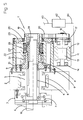
- the in the FIGS. 1 and 5 illustrated and denoted by 1 and 1 'clamping device is used to actuate a power tool chuck 3 arranged on a machine tool 2, by means of the radially adjustable clamping jaws 4 to be machined tool piece 10 in the power chuck 3 can be clamped.
- the clamping device 1 or 1 'in this case consists essentially of a switchable electric servomotor 11, one attached to a drivable by a motor 8 spindle 5 of the machine tool 2 by means of screws 9' fixed flange 9 mounted hollow shaft 21 and a bell 22, via Rolling bearings 24 and 25 on the Hollow shaft 21 is rotatably mounted and drivingly connected to the servo motor 11.
- the servomotor 11 has a stator 12, which is supported in a carrier 15 fastened to the machine tool 2 by means of screws 16, and a rotor 13 rotatably mounted in the stator 11 by means of roller bearings 14.
- a gear 18 is arranged, which is drivingly connected via an engaging in this toothed belt 20 with a gear 19, which is worked on the bell 22.
- the bell 22 is thus driven by the switchable servo motor 11 in both directions of rotation.
- the bell 22 is further drivingly connected to a pull rod 6 or on one of these attached extension piece 6', which acts on the clamping jaws 4 via lever 7.
- the clamping jaws 4 are thus adjusted to the outside, with an adjustment to the right, however, inwardly in the direction of the workpiece 10.
- the deflecting member 26 is shown in FIGS FIGS. 1 and 2 designed as Rollendoilztrieb.
- the deflection member 26 ' consists of two interlocking threaded spindles 38 and 40, on the one hand in the bell 22' and on the other hand in a attached to the extension piece 6 'of the tie rod 6 a machined into the hollow shaft 21 cutout 21' thorough approach 39 are worked.
- servomotor 11 and the bell 22 and 22 'and 22 "differently shaped deflection members 27 and 28 arranged as a reduction gear. of the toothed belt 20 is drivable.
- the ring gear 35 is in this case provided on the bell 22 'and the planetary gears 34 are mounted by means of projecting pins 36 and bearings 37 rotatably mounted in the hollow shaft 21, so that an introduced via the toothed belt 20 torque on the bell 22' at reduced speed can be transmitted.
- the deflection member 28 may be formed as a wave gear 41.
- an oval shaped projection 43 ' is formed on which by means of a roller bearing 44 and provided with a toothing 45 coupling part 42 are supported.
- the coupling part 42 is circumferentially introduced according to the oval configuration of the extension piece 43 'in a toothing 46 incorporated on the bell 22'.
- the coupling part 42 is supported by means of a projection 47 in a groove 48.
- the clamping force exerted on it is to be increased or reduced, since, for example, the type of machining has been changed, then the output torque of the servomotor 11 or its rotational speed is synchronized with the hollow shaft during operation 21 is driven to change.
- the bell 22 is driven with respect to the hollow shaft 21 at a slightly higher or a slightly lower speed, so that the pull rod 6 is displaced to the left to reduce the clamping force of the power chuck 3 or to the right to increase the clamping force.
- the torque output by the servomotor 11 the clamping force of the power chuck 3 is thus adjusted to changed operating conditions.
- the clamping force of the power chuck 3 can be determined.
- the servomotor 11 is as shown in FIG. 1 is shown connected by means of a control line 61 to the control, not shown, of the machine tool 2, so that a synchronous operation with the motor 8 is given.
- FIG. 5 can the amount of torque of the servo motor 11 and its speed, which in this case in a flange 23 which is attached via an intermediate piece 23 'to the machine tool 2 and in which by means of a rolling bearing 25', the bell 22 is mounted, by means of a separate control unit 62 are changed, which is connected via a line 63 to the machine control and connected via a signal line 64 to the servo motor 14.
- the clamping device 1 which consists essentially of a counter to the force of a spring 55th axially displaceable safety pin 52 consists.
- the securing bolt 52 automatically engages in a recess 57 provided in the hollow shaft 21.
- the safety pin 52 which is adjustably guided in an incorporated into the bell 22 bore 53, held against the force of the spring 54 supported on a shoulder 55 by a cooperating with a molded collar 58 electromagnet 56 in the operating position shown, as soon as However, the force of the electromagnet 56 is no longer effective, the securing bolt 52 is inserted immediately into the recess 57 and the bell 22 is rigidly coupled to the hollow shaft 21, so that no adjustment movements are executable.
Priority Applications (1)
| Application Number | Priority Date | Filing Date | Title |
|---|---|---|---|
| EP08005261A EP2103368A1 (fr) | 2008-03-20 | 2008-03-20 | Dispositif de tension pour machines-outils |
Applications Claiming Priority (1)
| Application Number | Priority Date | Filing Date | Title |
|---|---|---|---|
| EP08005261A EP2103368A1 (fr) | 2008-03-20 | 2008-03-20 | Dispositif de tension pour machines-outils |
Publications (1)
| Publication Number | Publication Date |
|---|---|
| EP2103368A1 true EP2103368A1 (fr) | 2009-09-23 |
Family
ID=39616488
Family Applications (1)
| Application Number | Title | Priority Date | Filing Date |
|---|---|---|---|
| EP08005261A Withdrawn EP2103368A1 (fr) | 2008-03-20 | 2008-03-20 | Dispositif de tension pour machines-outils |
Country Status (1)
| Country | Link |
|---|---|
| EP (1) | EP2103368A1 (fr) |
Cited By (9)
| Publication number | Priority date | Publication date | Assignee | Title |
|---|---|---|---|---|
| EP2363223A1 (fr) * | 2010-03-02 | 2011-09-07 | Karl Hiestand | Dispositif de serrage pour machines-outils |
| EP2384839A1 (fr) * | 2010-05-04 | 2011-11-09 | Karl Hiestand | Dispositif de tension |
| JP2013022725A (ja) * | 2011-07-19 | 2013-02-04 | Karl Hiestand | 機械工具用クランプ装置 |
| CN104117703A (zh) * | 2013-04-24 | 2014-10-29 | 卡尔·希斯坦德 | 联接器具 |
| EP2868410A1 (fr) | 2013-10-30 | 2015-05-06 | MTH GbR Markus und Thomas Hiestand | Dispositif de serrage pour machines-outils |
| EP2799169A3 (fr) * | 2013-05-02 | 2015-08-05 | ARTIS GmbH | Procédé et dispositif de réglage d'outils réglables montés sur une broche de moteur d'une machine-outil |
| EP2363224A3 (fr) * | 2010-03-02 | 2016-05-25 | Karl Hiestand | Dispositif de serrage pour machines-outils |
| CN108237406A (zh) * | 2018-03-06 | 2018-07-03 | 北京市电加工研究所 | 基于伺服电机控制的数控分度与高速旋转加工双用轴系统 |
| EP2853326B1 (fr) * | 2010-08-23 | 2021-03-03 | EV Group GmbH | Mandrin de serrage à couplage automatique |
Citations (12)
| Publication number | Priority date | Publication date | Assignee | Title |
|---|---|---|---|---|
| GB2067931A (en) * | 1980-01-16 | 1981-08-05 | Baruffaldi Frizioni Spa | Chucks |
| DE3218084A1 (de) * | 1982-05-13 | 1983-11-17 | Hubert Dipl.-Ing. 5920 Bad Berleburg Bald | Vorrichtung zum erzeugen einer stelldrehbewegung |
| US4573379A (en) * | 1982-05-13 | 1986-03-04 | Hubert Bald | Apparatus for producing an adjusting torque |
| EP0228007A2 (fr) * | 1985-12-28 | 1987-07-08 | Paul Forkardt GmbH & Co. KG | Machine-outil et son mode d'action |
| US4964322A (en) * | 1987-09-03 | 1990-10-23 | Gte Valenite Corporation | Dynamic differential drive |
| US6079303A (en) * | 1998-04-03 | 2000-06-27 | N. T. Naum Technologies Ltd. | Automatic adjustable power chuck system and method |
| DE10101095A1 (de) * | 2001-01-12 | 2002-07-25 | Ortlieb Praez S Spannzeuge Gmb | Spanneinrichtung für Werkzeuge, Werkzeughalter oder dergleichen |
| EP1264653A2 (fr) * | 2001-06-01 | 2002-12-11 | Ex-Cell-O GmbH | Broche |
| EP1453638A1 (fr) * | 2001-12-11 | 2004-09-08 | Paul Müller GmbH & Co. KG Unternehmensbeteiligungen | Dispositif pour fixer un outil sur un arbre et broche de machine comportant un tel dispositif |
| US20060027980A1 (en) * | 2004-08-05 | 2006-02-09 | Karl Hiestand | Clamping device for machine tools |
| WO2006034869A1 (fr) * | 2004-09-30 | 2006-04-06 | Cmt Tubertini Srl | Equipement de commande electronique pour broches |
| WO2007013107A1 (fr) * | 2005-07-27 | 2007-02-01 | Rpm Tecnologie S.R.L. | Broche a deux arbres |
-
2008
- 2008-03-20 EP EP08005261A patent/EP2103368A1/fr not_active Withdrawn
Patent Citations (14)
| Publication number | Priority date | Publication date | Assignee | Title |
|---|---|---|---|---|
| GB2067931A (en) * | 1980-01-16 | 1981-08-05 | Baruffaldi Frizioni Spa | Chucks |
| DE3218084A1 (de) * | 1982-05-13 | 1983-11-17 | Hubert Dipl.-Ing. 5920 Bad Berleburg Bald | Vorrichtung zum erzeugen einer stelldrehbewegung |
| US4573379A (en) * | 1982-05-13 | 1986-03-04 | Hubert Bald | Apparatus for producing an adjusting torque |
| EP0228007A2 (fr) * | 1985-12-28 | 1987-07-08 | Paul Forkardt GmbH & Co. KG | Machine-outil et son mode d'action |
| US4964322A (en) * | 1987-09-03 | 1990-10-23 | Gte Valenite Corporation | Dynamic differential drive |
| US6079303A (en) * | 1998-04-03 | 2000-06-27 | N. T. Naum Technologies Ltd. | Automatic adjustable power chuck system and method |
| DE10101095A1 (de) * | 2001-01-12 | 2002-07-25 | Ortlieb Praez S Spannzeuge Gmb | Spanneinrichtung für Werkzeuge, Werkzeughalter oder dergleichen |
| EP1264653A2 (fr) * | 2001-06-01 | 2002-12-11 | Ex-Cell-O GmbH | Broche |
| EP1453638A1 (fr) * | 2001-12-11 | 2004-09-08 | Paul Müller GmbH & Co. KG Unternehmensbeteiligungen | Dispositif pour fixer un outil sur un arbre et broche de machine comportant un tel dispositif |
| US20060027980A1 (en) * | 2004-08-05 | 2006-02-09 | Karl Hiestand | Clamping device for machine tools |
| EP1637260A1 (fr) * | 2004-08-05 | 2006-03-22 | Karl Hiestand | Dispositif de verrouillage pour machine outil |
| EP1637260B1 (fr) | 2004-08-05 | 2007-10-03 | Karl Hiestand | Dispositif de verrouillage pour machine outil |
| WO2006034869A1 (fr) * | 2004-09-30 | 2006-04-06 | Cmt Tubertini Srl | Equipement de commande electronique pour broches |
| WO2007013107A1 (fr) * | 2005-07-27 | 2007-02-01 | Rpm Tecnologie S.R.L. | Broche a deux arbres |
Cited By (12)
| Publication number | Priority date | Publication date | Assignee | Title |
|---|---|---|---|---|
| EP2363223A1 (fr) * | 2010-03-02 | 2011-09-07 | Karl Hiestand | Dispositif de serrage pour machines-outils |
| EP2363224A3 (fr) * | 2010-03-02 | 2016-05-25 | Karl Hiestand | Dispositif de serrage pour machines-outils |
| EP2384839A1 (fr) * | 2010-05-04 | 2011-11-09 | Karl Hiestand | Dispositif de tension |
| JP2011235436A (ja) * | 2010-05-04 | 2011-11-24 | Karl Hiestand | クランプ装置 |
| EP2853326B1 (fr) * | 2010-08-23 | 2021-03-03 | EV Group GmbH | Mandrin de serrage à couplage automatique |
| JP2013022725A (ja) * | 2011-07-19 | 2013-02-04 | Karl Hiestand | 機械工具用クランプ装置 |
| CN104117703A (zh) * | 2013-04-24 | 2014-10-29 | 卡尔·希斯坦德 | 联接器具 |
| EP2796233A1 (fr) * | 2013-04-24 | 2014-10-29 | Karl Hiestand | Dispositif de couplage |
| EP2799169A3 (fr) * | 2013-05-02 | 2015-08-05 | ARTIS GmbH | Procédé et dispositif de réglage d'outils réglables montés sur une broche de moteur d'une machine-outil |
| EP2868410A1 (fr) | 2013-10-30 | 2015-05-06 | MTH GbR Markus und Thomas Hiestand | Dispositif de serrage pour machines-outils |
| CN108237406A (zh) * | 2018-03-06 | 2018-07-03 | 北京市电加工研究所 | 基于伺服电机控制的数控分度与高速旋转加工双用轴系统 |
| CN108237406B (zh) * | 2018-03-06 | 2024-02-27 | 北京市电加工研究所有限公司 | 基于伺服电机控制的数控分度与高速旋转加工双用轴系统 |
Similar Documents
| Publication | Publication Date | Title |
|---|---|---|
| EP2103368A1 (fr) | Dispositif de tension pour machines-outils | |
| EP2295176B1 (fr) | Agrégat de serrage | |
| EP2384839B1 (fr) | Dispositif de tension | |
| EP3040144B1 (fr) | Dispositif de serrage | |
| EP1637260B1 (fr) | Dispositif de verrouillage pour machine outil | |
| EP2517811B1 (fr) | Dispositif de forage | |
| DE3509635C1 (de) | Werkzeughalteeinrichtung fuer Drehmaschinen | |
| EP2796233A1 (fr) | Dispositif de couplage | |
| WO2017215881A1 (fr) | Dispositif de serrage | |
| DE4201849C1 (fr) | ||
| EP2218531B1 (fr) | Dispositif de tension pour machines-outils | |
| EP2363223B1 (fr) | Dispositif de serrage pour machines-outils | |
| DE10164723B4 (de) | Spindelanordnung für eine Werkzeugmaschine | |
| EP2769788B1 (fr) | Dispositif de tension pour machines-outils | |
| EP2283955A1 (fr) | Dispositif de serrage pour machines-outils | |
| EP2724801A1 (fr) | Agrégat de serrage | |
| EP1163976A1 (fr) | Entrainement avec une transmission variable pour un dispositif porte outil | |
| DE102019105643A1 (de) | Spanneinrichtung | |
| DE102010007399B4 (de) | Werkstück- oder Werkzeughaltevorrichtung einer Werkzeugmaschine | |
| EP3127640B1 (fr) | Dispositif de serrage | |
| DE4005181C1 (en) | Machine tool work spindle drive - has angularly adjustable motor with spur gearing controlled via pawl | |
| EP3822008B1 (fr) | Ensemble broche pour une machine outil | |
| EP2363224A2 (fr) | Dispositif de serrage pour machines-outils | |
| DE3436470C2 (fr) | ||
| DE4244042C1 (de) | Vorrichtung zum Trennen oder Abstechen vergleichsweise langer Werkstücke |
Legal Events
| Date | Code | Title | Description |
|---|---|---|---|
| PUAI | Public reference made under article 153(3) epc to a published international application that has entered the european phase |
Free format text: ORIGINAL CODE: 0009012 |
|
| AK | Designated contracting states |
Kind code of ref document: A1 Designated state(s): AT BE BG CH CY CZ DE DK EE ES FI FR GB GR HR HU IE IS IT LI LT LU LV MC MT NL NO PL PT RO SE SI SK TR |
|
| AX | Request for extension of the european patent |
Extension state: AL BA MK RS |
|
| 17P | Request for examination filed |
Effective date: 20100309 |
|
| 17Q | First examination report despatched |
Effective date: 20100423 |
|
| AKX | Designation fees paid |
Designated state(s): AT BE BG CH CY CZ DE DK EE ES FI FR GB GR HR HU IE IS IT LI LT LU LV MC MT NL NO PL PT RO SE SI SK TR |
|
| STAA | Information on the status of an ep patent application or granted ep patent |
Free format text: STATUS: THE APPLICATION HAS BEEN WITHDRAWN |
|
| 18W | Application withdrawn |
Effective date: 20100816 |