EP3127640B1 - Dispositif de serrage - Google Patents
Dispositif de serrage Download PDFInfo
- Publication number
- EP3127640B1 EP3127640B1 EP15179801.4A EP15179801A EP3127640B1 EP 3127640 B1 EP3127640 B1 EP 3127640B1 EP 15179801 A EP15179801 A EP 15179801A EP 3127640 B1 EP3127640 B1 EP 3127640B1
- Authority
- EP
- European Patent Office
- Prior art keywords
- pulley
- clamping device
- drive
- clamping
- belt
- Prior art date
- Legal status (The legal status is an assumption and is not a legal conclusion. Google has not performed a legal analysis and makes no representation as to the accuracy of the status listed.)
- Active
Links
- 230000033001 locomotion Effects 0.000 claims description 25
- 230000008878 coupling Effects 0.000 claims description 11
- 238000010168 coupling process Methods 0.000 claims description 11
- 238000005859 coupling reaction Methods 0.000 claims description 11
- 238000006073 displacement reaction Methods 0.000 claims description 5
- 238000012544 monitoring process Methods 0.000 claims description 4
- 230000002441 reversible effect Effects 0.000 claims 2
- 230000000712 assembly Effects 0.000 description 2
- 238000000429 assembly Methods 0.000 description 2
- 238000010276 construction Methods 0.000 description 2
- 238000000034 method Methods 0.000 description 2
- 230000001960 triggered effect Effects 0.000 description 2
- 230000005540 biological transmission Effects 0.000 description 1
- 230000000903 blocking effect Effects 0.000 description 1
- 238000005265 energy consumption Methods 0.000 description 1
- 238000003754 machining Methods 0.000 description 1
- 238000004519 manufacturing process Methods 0.000 description 1
- 125000006850 spacer group Chemical group 0.000 description 1
- 230000001360 synchronised effect Effects 0.000 description 1
- 238000011144 upstream manufacturing Methods 0.000 description 1
Images


Classifications
-
- B—PERFORMING OPERATIONS; TRANSPORTING
- B23—MACHINE TOOLS; METAL-WORKING NOT OTHERWISE PROVIDED FOR
- B23B—TURNING; BORING
- B23B31/00—Chucks; Expansion mandrels; Adaptations thereof for remote control
- B23B31/02—Chucks
- B23B31/24—Chucks characterised by features relating primarily to remote control of the gripping means
- B23B31/28—Chucks characterised by features relating primarily to remote control of the gripping means using electric or magnetic means in the chuck
Definitions
- the invention relates to a clamping device, in particular for machine tools, which is provided, for example, with a power chuck for holding a workpiece and whose clamping jaws can be adjusted by means of the clamping device via an axially adjustable drawbar as an actuating element, the clamping device having a switchable electric drive motor for triggering clamping movements, the is connected to the clamping device via drive trains, has a movement converter for converting the adjustment movements of the rotor shaft of the drive motor into the axial adjustment movements of the pull rod required to actuate the clamping jaws, and an energy accumulator for maintaining the clamping force.
- the EP 2 295 176 A1 shows a clamping device according to the preambles of claims 1 and 6 for machine tools, with a power chuck for holding a workpiece, the clamping jaws of the clamping device being adjustable via an axially adjustable drawbar as an actuating element.
- the clamping device has a switchable electric drive motor for triggering clamping movements, which is connected to the clamping device via drive trains, as well as a movement converter for converting the adjustment movements of the rotor shaft of the drive motor into the axial adjustment movements of the pull rod required to actuate the clamping jaws.
- the two drive trains are formed from a first and a second belt drive, each consisting of two belt pulleys and a toothed belt or drive belt guided over them.
- a support hub is arranged in a rotationally fixed manner, on which the pulley of the first belt drive is rotationally fixed and the pulley of the second belt drive is rotatably mounted.
- the two belt pulleys arranged on the supporting hub can be coupled to one another with the aid of a servo device.
- the DE 10 2007 042 432 B4 discloses such a clamping unit.
- the two drive trains provided between the drive motor and the motion converter are formed by gearwheel sets which are switched in a controlled manner by means of electric clutches.
- the gear sets have to be arranged in an oil bath due to the high speeds required, the effort involved in switching the electric clutches alternately is therefore very high.
- one clutch is to be closed, but at the same time the other clutch is to be opened in order to separate the drive train, which can be influenced by this, from the rotor shaft of the drive motor.
- a drive train must be connected to the rotor shaft in a drive-resistant and slip-free manner, and the drive motor must be decoupled via the other clutch.
- the slip-free synchronous operation of the two gear sets must be monitored during operation, otherwise the power chuck will be opened by the clamping device. This requires a large control capacity, which experience has shown is prone to failure. A safe mode of operation, which is often required, is therefore not given with this known clamping device.
- the object of the invention is therefore to design the clamping device of the type mentioned at the outset in such a way that the control and construction costs can be kept extremely low and can be accomplished with the aid of a standard NC control. This is intended to reduce the susceptibility to faults to a minimum, so that safe operation of the clamping device is ensured over a longer period of time. Furthermore, it should be achieved that no gear sets to be arranged in an oil bath are required and that during operation the drive motor is easy to decouple from the clamping device in order to keep the energy consumption low. In the event of damage to components, a blocking should also be reliably triggered automatically, so that the risk of accidents is reduced.
- a clamping device according to claim 1 or according to claim 6.
- the two drive trains are formed from a first and a second, each consisting of two belt pulleys and a belt drive which is guided over these toothed belts or drive belts, with a supporting hub being arranged in a rotationally fixed manner on the rotor shaft of the drive motor, on which the belt pulley of the first belt drive are non-rotatably mounted and the belt pulley of the second belt drive is rotatably mounted, with the two belt pulleys arranged on the support hub being able to be coupled to one another in the tensioning position of the tensioning device with the aid of a servo device.
- the pulley which is rotatably mounted on the support hub, is to be coupled to the stationary pulley by means of an axially displaceable intermediate member, which is connected to the servo device, the intermediate member being firmly connected to a toothed pulley which is arranged between the two pulleys and has teeth , which interacts with a counter-toothing attached to the stationary pulley.
- the intermediate member In order to have a backup in the event of a failure of the servo device by automatically causing a blockage via the intermediate member, it is preferable to support the intermediate member directly or via the toothed disc attached to it by the force of springs in the axial direction on the pulley of the second belt drive, so that the two pulleys are fixed to one another are connected and the clamping device is blocked.
- the servo device can be formed from a pressure piston which is inserted in a cylinder and can be acted upon on both sides by pressure medium, which is rotatably mounted on the intermediate member and is coupled to it in both axial directions.
- pressure medium which is rotatably mounted on the intermediate member and is coupled to it in both axial directions.
- a travel sensor for monitoring the adjustment travel of the connecting link can be assigned to the servo device.
- the belt pulley of the first belt drive is rotatably mounted on the support hub.
- a sliding sleeve is to be provided for the non-rotatable connection of the pulley to the hub, which is non-rotatably connected to the hub and can be coupled to the pulley with the aid of the servo device, preferably via a toothed clutch.
- the coupling devices are each formed from two thrust washers arranged on the outside of the belt pulleys so that they can be displaced axially to a limited extent and one or more axially displaceable locking bolts inserted into one of the thrust washers, which are supported on the thrust washer and are actuated by the force of Springs can be inserted into associated recesses provided in the opposite pulley.
- a tensioning device in which the drive trains are designed as belt drives and a supporting hub is firmly arranged on the rotor shaft of the drive motor, which hub carries belt pulleys that can be coupled by means of a servo device, it is possible to use the drive motor and the servo device with Easily adapted to the respective circumstances with the help of existing NC controls, so that safe and trouble-free operation is guaranteed over a long period of time. It is also ensured that, for example, if a toothed belt or drive belt breaks, the pulleys connected to the drive members of the tensioning device are blocked immediately and automatically.
- the drive of the clamping device is thus guaranteed without the interposition of a reduction or transmission gear and without complex controls.
- the construction cost is therefore low.
- an AC or DC motor can be used, which can also be shut down during operation. It is therefore not only a small manufacturing effort required to create an electrical clamping device, but it also keeps its operating costs low, and there is always trouble-free operation.
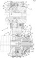
- the clamping device shown and labeled 1 serves to actuate a power chuck 5 arranged on a machine tool 2, by means of which radially adjustable clamping jaws 6 a workpiece 10 to be machined is clamped in the power chuck 5.
- the clamping jaws 6 of the power chuck 5 can be actuated via deflection levers 8 by an axially adjustable two-part pull rod 7, 7', which is in drive connection with a switchable electric drive motor 11 via a motion converter 15.
- the rotary adjustment movements of the drive motor 11 are converted into axial feed movements of the pull rod 7, 7' by means of the movement converter 15.
- An electric motor 4 acts on the machine spindle 3 and can be used to drive the machine tool 2 .
- the tensioning device 1 has a housing 17 in which the movement converter 15 and an energy accumulator 16 formed by spring assemblies 20 and 20' are accommodated.
- On the machine tool 2 side facing the housing 17 is provided with a protruding web on which a flange is attached.
- the flange is attached to a further flange 9 formed on the machine spindle 3 with the aid of screws.
- the drive energy is supplied to the motion converter 15 via intermediate members 19 which are in drive connection with a spindle nut 18 .
- the spindle nut 18, on which the spring assemblies 20 and 20' of the force accumulator 16 act during clamping processes the rotational movements introduced are transmitted to the drawbar 7' and thereby converted into axial feed movements depending on the direction of rotation.
- the drive motor 11 is in drive connection with the clamping device 1 via two drive trains 21 and 31 .
- a support hub 13 is arranged on the rotor shaft 12 of the drive motor 11 in a rotationally fixed manner with the aid of a splined connection 25 and is secured to the rotor shaft 12 by means of a screw 14 .
- Belt pulleys 22 and 32 of two belt drives 21' and 31', which form the drive trains 21 and 31, are arranged on the supporting hub 13.
- One of the belt pulleys, namely the belt pulley 22 is in turn connected to the supporting hub 13 in a rotationally fixed manner by means of a splined connection 26 .
- the belt pulley 32 of the belt drive 31' is rotatably mounted on the support hub 13.
- the pulleys 22 and 32 are drivingly connected to pulleys 23 and 33 , which are coupled to drive members of the tensioning device 1 , via toothed belts or drive belts 24 and 34 .
- the belt pulley 23 is rotatably mounted on a hollow shaft 27 by means of roller bearings 28 and is connected to the intermediate members 19 via a toothing 30 provided on a shoulder 29 .
- the pulley 33 on the other hand, is firmly attached to the hollow shaft 27 with the aid of screws 38.
- the belt pulley 32 of the belt drive 31 is rotatably supported on the supporting hub 13 by means of a roller bearing 36 and a supporting disk 35 .
- the belt pulley 32 is secured to the support pulley 35 by means of screws 37 .
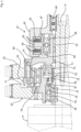
- the pulley 32 is connected to an intermediate link 44 connected, namely how this particular the figures 2 and 3 can be seen, with the help of sleeves 48, which are inserted into bores 47 worked into the pulley 32, and screws 49, which pass through the sleeve 48 and by which the intermediate member 44 is connected to a toothed pulley 46 arranged between the two pulleys 32 and 22 is.
- the intermediate member 44 is arranged to be displaceable on the support hub 13 via a sliding bearing 45 .
- a servo device 51 or 61 is used to actuate the intermediate member 44 Figure 1 to 3
- the exemplary embodiment shown consists of a cylinder 52 which is stationary and rotatable on the support hub 13 by means of a bearing 59 and a piston 53 which is inserted in this cylinder and is axially displaceable and can be acted upon on both sides by pressure medium.
- a control valve 60 can be used to alternately supply pressure medium from a pressure medium supply line 60' to the pressure chambers 54 or 55 in order to move the intermediate member 44 to the left or right, depending on the operating state.
- the pressure piston 53 is rotatably arranged on the intermediate member 44 by means of a roller bearing 56 , it is firmly connected to the intermediate member 44 in the axial direction by means of a molded nose 57 and a snap ring 58 .
- the intermediate member 44 can be mechanically coupled via a gear coupling 41 to the belt pulley 22 of the belt drive 21'.
- toothing 42 is attached to the side surface facing intermediate member 44, and toothed disc 46, which is firmly connected to intermediate member 44, is equipped with counter-toothing 43, which can be inserted into toothing 42 with the aid of servo device 51.
- the two belt pulleys 22 and 32 are firmly connected to one another and the clamping device 1 is blocked, so that machining processes can be carried out.
- the toothed disk 46 and the intermediate element 44 firmly connected to it are automatically axial by means of blind bores 50' worked into the intermediate element 44 and blind bores 50" provided in the toothed disk 46 If the servo device 51 fails, the toothing 43 snaps into the toothing 42 by means of an axial displacement to the left, triggered by the force of the springs 50, so that the two belt drives 21' and 31' are blocked.
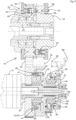
- the servo device 61 can also, as in the figures 4 and 5 shown, consist of two magnetic coils 63 and 64 which are inserted in a housing 62 supported on the supporting hub 13 by means of a roller bearing 69 and which cooperate with an axially displaceable armature 65 .
- the armature 65 is in turn coupled by means of integrally formed lugs 66 and 67 to a roller bearing 68 which is inserted into the intermediate member 44 mounted on the support hub 13 by means of roller bearings 70 .
- the toothed clutch 41 is thus opened ( figure 4 ).
- the gear coupling 41 is closed by an axial displacement of the armature 65 to the left.
- the belt pulley 22 ′ is also arranged rotatably on the supporting hub 13 by means of a roller bearing 76 .
- a sliding sleeve 71 that can be actuated by the intermediate piece 44 is provided, which is non-rotatably connected to the supporting hub 13 by means of a wedge connection 72 and can be coupled to an intermediate member 75 by axial displacement.
- the intermediate piece 75, on which the pulley 32 is supported with the aid of roller bearings 80, is firmly connected to the pulley 22' by means of screws 79.
- FIG 1 the operating position of the clamping device 1 is shown during operations.
- the workpiece 10 clamped in the power chuck 5 can be machined according to the specifications.
- the two belt drives 21' and 31' are connected to one another via the toothed coupling 41 and rotate together with the support hub 13.
- the connection between the two belt drives 21' and 31' must be released with the aid of the servo device 51 by opening the toothed clutch 41 and energy is to be supplied to the tensioning device 1 via the belt drive 21' with the aid of the drive motor 11.
- the belt pulley 22 is rotated and also the threaded nut 18 connected to it via intermediate members 19, so that the pull rod 7' is displaced axially by this and the clamping jaws 6 are adjusted inwards or outwards.
- the workpiece 10 can thus be removed or another workpiece can be used. After completion of this work process is again by means of the servo device 51 the in figure 1 to produce the operating state shown.
- the pulleys 23 and 33 are each assigned a coupling device 91 or 91'.
- the coupling devices 91 and 91' each consist of slightly axially displaceable thrust washers 92 and 93, which are arranged on the outer sides of the pulleys 23 and 33, and locking bolts 95, which can be coupled to the opposite pulley 33 or 23, respectively.
- the thrust washers 92 and 93 are each slidably mounted on pins 94 and lie on the toothed or drive belts 24 and 34 on the side.
- the thrust washer 92 or 93 is pushed in the direction of the belt pulleys 23 or 33 by the force of springs 97, which act on the locking bolts 95 and to which the thrust washers 92, 93 are connected by means of screws 98, so that the locking bolts 95 engage in associated recesses 96 provided on the opposite pulleys 33 and 23, respectively, so that the two pulleys 23 and 33 are thus firmly connected to one another. In this case, the clamping device 1 is again blocked.
- the servo device 51 is associated with a displacement sensor 81 by means which the adjustment of the intermediate member 44 is to be monitored.
- the drive motor 11 is equipped with a sensor 82 for monitoring the motor speed, which is connected directly to a control unit 85 upstream of the drive motor 11 .
- the pull rod 7 interacts with a sensor 83, by means of which its adjustment path can be controlled.
- the energy accumulator 16 is also equipped with a sensor 84 in order to be able to detect the given clamping force of the power chuck 5.
Claims (10)
- Dispositif de serrage (1) en particulier pour des machines-outils (2) qui sont pourvues par exemple d'un mandrin de serrage (5) pour maintenir une pièce (10) et dont les mâchoires de serrage (6) peuvent être ajustées au moyen du dispositif de serrage (1) sur une tige de traction (7, 7') pouvant être ajustée axialement en tant qu'organe d'actionnement, dans lequel le dispositif de serrage (1) présente un moteur électrique d'entraînement (11) commutable pour déclencher des mouvements de serrage, deux chaînes cinématiques (21, 31) reliées au moteur d'entraînement (11), ainsi qu'un convertisseur de déplacement (15) pour convertir les déplacements d'ajustement de l'arbre de rotor (12) du moteur d'entraînement (11) en les déplacements d'ajustement axiaux de la tige de traction (7, 7') requis pour l'actionnement des mâchoires de serrage (6),
dans lequel les deux chaînes cinématiques (21, 31) sont formées à partir d'un premier et d'un deuxième entraînement à courroie (21', 31') constitués respectivement de deux poulies (22, 23 ou 32, 33) et d'une courroie dentée ou de transmission (24, 34) guidée par l'intermédiaire de celles-ci, dans lequel est disposé, de manière solidaire en rotation, sur l'arbre de rotor (12) du moteur d'entraînement (11) un moyeu de support (13), sur lequel la poulie (22) du premier entraînement à courroie (21') est montée de manière solidaire en rotation et la poulie (32) du deuxième entraînement à courroie (31') est montée de manière à pouvoir tourner, dans lequel en position de serrage du dispositif de serrage (1), les deux poulies (32, 32) disposées sur le moyeu de support (13) peuvent être couplées l'une à l'autre à l'aide d'un dispositif d'asservissement (51),caractérisé en ce que le dispositif de serrage (1) présente un accumulateur de force (16) pour maintenir la force de serrage, et que la poulie (32) montée de manière à pouvoir tourner sur le moyeu de support (13) peut être reliée à la poulie (22) disposée de manière solidaire en rotation au moyen d'un organe intermédiaire (44) pouvant être coulissé axialement, qui est actionnable au moyen du dispositif d'asservissement (51),et que l'organe intermédiaire (44) est relié de manière solidaire à une rondelle dentée (46) disposée entre les deux poulies (22, 32), qui présente une denture (43) qui coopère avec une contre-denture (42) installée sur la poulie (22) disposée de manière solidaire en rotation. - Dispositif de serrage selon la revendication 1, caractérisé en ce que
l'organe intermédiaire (44) est soutenu directement ou par l'intermédiaire de la rondelle crantée (46) installée sur celui-ci par la force de ressorts (50) dans une direction axiale sur la poulie (32) du deuxième entraînement à courroie (31'). - Dispositif de serrage selon la revendication 1 ou 2,
caractérisé en ce que le dispositif d'asservissement (51) est formé à partir d'un piston de pression (54) inséré dans un cylindre (53) et pouvant être soumis de part et d'autre à l'action de moyens de pression, qui est monté de manière à pouvoir tourner sur l'organe intermédiaire (44) et qui est couplé à celui-ci dans deux directions axiales. - Dispositif de serrage selon la revendication 1 ou 2,
caractérisé en ce que le dispositif d'asservissement (61) est formé à partir de deux bobines magnétiques (63, 64) disposées de manière stationnaire et d'un ancrage (65) pouvant être coulissé axialement, qui est monté de manière à pouvoir tourner sur l'organe intermédiaire (44) et est couplé à celui-ci dans les deux directions axiales. - Dispositif de serrage selon l'une des revendications précédentes 3 ou 4,
caractérisé en ce qu'un capteur de déplacement (81) pour surveiller le trajet d'ajustement de l'organe intermédiaire (44) est affecté au dispositif d'asservissement (51). - Dispositif de serrage (1), en particulier pour des machines-outils (2) qui sont pourvues par exemple d'un mandrin de serrage (5) pour maintenir une pièce (10) et dont les mâchoires de serrage (6) peuvent être ajustées au moyen du dispositif de serrage (1) par l'intermédiaire d'une tige de traction (7, 7') pouvant être ajustée axialement en tant qu'organe d'actionnement, dans lequel le dispositif de serrage (1) présente un moteur d'entraînement (11) électrique commutable pour déclencher des déplacements de serrage, deux chaînes cinématiques (21, 31) reliées au moteur d'entraînement (11), ainsi qu'un convertisseur de déplacement (15) pour convertir les déplacements d'ajustement de l'arbre de rotor (12) du moteur d'entraînement (11) en les déplacements d'ajustement axiaux de la tige de traction (7, 7') requis pour l'actionnement des mâchoires de serrage (6), dans lequel les deux chaînes cinématiques (21, 31) sont formées à partir d'un premier et d'un deuxième entraînements à courroie (21', 31') constitués respectivement de deux poulies (22', 23 ou 32, 33) et d'une courroie dentée ou de transmission (24, 34) guidée par l'intermédiaire de celles-ci, dans lequel est disposé, de manière solidaire en rotation, sur l'arbre de rotor (12) du moteur d'entraînement (11), un moyeu de support (13) sur lequel la poulie (22') du premier entraînement à courroie (21') et la poulie (32) du deuxième entraînement à courroie (31') sont montées, dans lequel en position de serrage du dispositif de serrage (1), les deux poulies (22', 32) disposées sur le moyeu de support (13) peuvent être couplées l'une à l'autre à l'aide d'un dispositif d'asservissement (61) et d'un organe intermédiaire (44) pouvant être coulissé axialement à travers celui-ci, caractérisé en ce que le dispositif de serrage présente un accumulateur de force (16) pour maintenir la force de serrage, que la poulie (22') du premier entraînement à courroie (21') et la poulie (32) du deuxième entraînement à courroie (31') sont montées de manière à pouvoir tourner sur le moyeu de support (13), que l'organe intermédiaire (44) est relié de manière solidaire à une rondelle crantée (46) disposée entre les deux poulies (22', 32), qui présente une denture (43) qui coopère avec une contre-denture (42) installée sur la poulie (22') du premier entraînement à courroie (21'), et que pour relier de manière solidaire en rotation la poulie (22) du premier entraînement à courroie (21') au moyeu de support (44), un manchon coulissant (71) est prévu, qui est relié de manière solidaire en rotation au moyeu de support (13) et qui peut être couplé à la poulie (22) à l'aide du dispositif d'asservissement (61), de préférence par l'intermédiaire d'un couplage denté (77, 78).
- Dispositif de serrage selon la revendication 6, caractérisé en ce que
Lorsque la poulie (22') du premier entraînement à courroie (21') est reliée de manière amovible au moyeu de support (13), un moteur à courant alternatif ou à courant continu est prévu en tant que moteur d'entraînement (11). - Dispositif de serrage selon l'une ou plusieurs des revendications 1 à 7,
caractérisé en ce qu'un capteur (82) destiné à déterminer et/ou à surveiller la vitesse de rotation de sortie est affecté au moteur d'entraînement (11). - Dispositif de serrage selon l'une ou plusieurs des revendications 1 à 8,
caractérisé en ce qu'une ou les deux des poulies (23, 33) disposées sur les organes d'entraînement (27) du dispositif de serrage (1) ou reliées à ceux-ci sont pourvues respectivement d'un dispositif de couplage (91, 91') efficace automatiquement dans le cas d'un endommagement d'une courroie dentée ou de transmission (24 ou 34), au moyen duquel les deux poulies (23, 33) peuvent être reliées l'une à l'autre par complémentarité de forme. - Dispositif de serrage selon la revendication 9, caractérisé en ce que
les dispositifs de couplage (91, 91') sont formés respectivement à partir de deux rondelles de butée (92, 93) disposées à coulissement axial de manière limitée sur les côtés extérieurs des poulies (23 ou 33) et d'un ou de plusieurs boulons d'enclenchement (93) insérés dans l'une des rondelles de butée (92) et pouvant être coulissés axialement, qui sont soutenus sur la rondelle de butée (92) et peuvent être introduits dans des évidements (96) associés prévus dans la poulie (33 ou 23) faisant face par la force de ressorts (97).
Priority Applications (1)
| Application Number | Priority Date | Filing Date | Title |
|---|---|---|---|
| EP15179801.4A EP3127640B1 (fr) | 2015-08-05 | 2015-08-05 | Dispositif de serrage |
Applications Claiming Priority (1)
| Application Number | Priority Date | Filing Date | Title |
|---|---|---|---|
| EP15179801.4A EP3127640B1 (fr) | 2015-08-05 | 2015-08-05 | Dispositif de serrage |
Publications (2)
| Publication Number | Publication Date |
|---|---|
| EP3127640A1 EP3127640A1 (fr) | 2017-02-08 |
| EP3127640B1 true EP3127640B1 (fr) | 2023-02-22 |
Family
ID=53783120
Family Applications (1)
| Application Number | Title | Priority Date | Filing Date |
|---|---|---|---|
| EP15179801.4A Active EP3127640B1 (fr) | 2015-08-05 | 2015-08-05 | Dispositif de serrage |
Country Status (1)
| Country | Link |
|---|---|
| EP (1) | EP3127640B1 (fr) |
Families Citing this family (1)
| Publication number | Priority date | Publication date | Assignee | Title |
|---|---|---|---|---|
| DE102020112170A1 (de) | 2020-05-06 | 2021-11-11 | Röhm Gmbh | Elektrische Betätigungseinheit für Werkzeugmaschinen |
Family Cites Families (6)
| Publication number | Priority date | Publication date | Assignee | Title |
|---|---|---|---|---|
| JP4917398B2 (ja) | 2006-09-27 | 2012-04-18 | オークマ株式会社 | 電動式チャック開閉装置 |
| EP2218531B1 (fr) * | 2009-02-11 | 2012-12-05 | Karl Hiestand | Dispositif de tension pour machines-outils |
| EP2283955A1 (fr) * | 2009-08-13 | 2011-02-16 | Karl Hiestand | Dispositif de serrage pour machines-outils |
| EP2295176B1 (fr) * | 2009-09-12 | 2018-11-07 | Karl Hiestand | Agrégat de serrage |
| EP2548681B1 (fr) * | 2011-07-19 | 2017-04-05 | Karl Hiestand | Dispositif de serrage pour machines-outils |
| DE102012011675B4 (de) * | 2012-06-14 | 2014-01-09 | Forkardt Deutschland Gmbh | Axialzugvorrichtung sowie Werkzeugmaschine mit einer Axialzugvorrichtung |
-
2015
- 2015-08-05 EP EP15179801.4A patent/EP3127640B1/fr active Active
Also Published As
| Publication number | Publication date |
|---|---|
| EP3127640A1 (fr) | 2017-02-08 |
Similar Documents
| Publication | Publication Date | Title |
|---|---|---|
| EP2311589B1 (fr) | Agrégat de serrage | |
| EP2384839B1 (fr) | Dispositif de tension | |
| EP2868410B1 (fr) | Dispositif de serrage pour machines-outils | |
| EP3040144B1 (fr) | Dispositif de serrage | |
| EP1637260A1 (fr) | Dispositif de verrouillage pour machine outil | |
| EP3362215B1 (fr) | Dispositif de serrage | |
| EP2796233A1 (fr) | Dispositif de couplage | |
| EP2103368A1 (fr) | Dispositif de tension pour machines-outils | |
| EP2218531B1 (fr) | Dispositif de tension pour machines-outils | |
| EP1728574A1 (fr) | Dispositif de serrage pour machine outil | |
| EP3059036A1 (fr) | Mandrin avec moteurs électriques | |
| WO2006136136A1 (fr) | Broche munie d'une barre de tension et d'un dispositif d'accouplement | |
| EP0436769B1 (fr) | Dispositif de génération d'une force de serrage dans un dispositif de serrage | |
| EP3127640B1 (fr) | Dispositif de serrage | |
| EP2363223B1 (fr) | Dispositif de serrage pour machines-outils | |
| EP2724801B1 (fr) | Agrégat de serrage | |
| EP2283955A1 (fr) | Dispositif de serrage pour machines-outils | |
| EP3448627B1 (fr) | Articulation motorisée pour un robot manipulateur programmable | |
| EP3175942B1 (fr) | Dispositif de serrage | |
| EP1237704A1 (fr) | Dispositif et procede permettant de realiser un mouvement lineaire en deux temps | |
| DE102019105643A1 (de) | Spanneinrichtung | |
| EP2837450B1 (fr) | Dispositif de serrage | |
| DE2233636C3 (de) | Einrichtung zum Steuern der Druckmittelzufuhr zu Spannzylindern oder kraftbetätigten Vorderendfuttern | |
| DE3546252A1 (de) | Werkzeugmaschine und deren betriebsverfahren | |
| EP0823967B1 (fr) | Dispositif de securite pour unite d'entrainement electro-hydraulique |
Legal Events
| Date | Code | Title | Description |
|---|---|---|---|
| PUAI | Public reference made under article 153(3) epc to a published international application that has entered the european phase |
Free format text: ORIGINAL CODE: 0009012 |
|
| STAA | Information on the status of an ep patent application or granted ep patent |
Free format text: STATUS: THE APPLICATION HAS BEEN PUBLISHED |
|
| AK | Designated contracting states |
Kind code of ref document: A1 Designated state(s): AL AT BE BG CH CY CZ DE DK EE ES FI FR GB GR HR HU IE IS IT LI LT LU LV MC MK MT NL NO PL PT RO RS SE SI SK SM TR |
|
| AX | Request for extension of the european patent |
Extension state: BA ME |
|
| STAA | Information on the status of an ep patent application or granted ep patent |
Free format text: STATUS: REQUEST FOR EXAMINATION WAS MADE |
|
| 17P | Request for examination filed |
Effective date: 20170412 |
|
| RBV | Designated contracting states (corrected) |
Designated state(s): AL AT BE BG CH CY CZ DE DK EE ES FI FR GB GR HR HU IE IS IT LI LT LU LV MC MK MT NL NO PL PT RO RS SE SI SK SM TR |
|
| STAA | Information on the status of an ep patent application or granted ep patent |
Free format text: STATUS: EXAMINATION IS IN PROGRESS |
|
| 17Q | First examination report despatched |
Effective date: 20200304 |
|
| STAA | Information on the status of an ep patent application or granted ep patent |
Free format text: STATUS: EXAMINATION IS IN PROGRESS |
|
| GRAP | Despatch of communication of intention to grant a patent |
Free format text: ORIGINAL CODE: EPIDOSNIGR1 |
|
| STAA | Information on the status of an ep patent application or granted ep patent |
Free format text: STATUS: GRANT OF PATENT IS INTENDED |
|
| INTG | Intention to grant announced |
Effective date: 20221004 |
|
| GRAS | Grant fee paid |
Free format text: ORIGINAL CODE: EPIDOSNIGR3 |
|
| GRAA | (expected) grant |
Free format text: ORIGINAL CODE: 0009210 |
|
| STAA | Information on the status of an ep patent application or granted ep patent |
Free format text: STATUS: THE PATENT HAS BEEN GRANTED |
|
| AK | Designated contracting states |
Kind code of ref document: B1 Designated state(s): AL AT BE BG CH CY CZ DE DK EE ES FI FR GB GR HR HU IE IS IT LI LT LU LV MC MK MT NL NO PL PT RO RS SE SI SK SM TR |
|
| REG | Reference to a national code |
Ref country code: GB Ref legal event code: FG4D Free format text: NOT ENGLISH |
|
| REG | Reference to a national code |
Ref country code: CH Ref legal event code: EP |
|
| REG | Reference to a national code |
Ref country code: DE Ref legal event code: R096 Ref document number: 502015016269 Country of ref document: DE |
|
| REG | Reference to a national code |
Ref country code: AT Ref legal event code: REF Ref document number: 1549192 Country of ref document: AT Kind code of ref document: T Effective date: 20230315 Ref country code: IE Ref legal event code: FG4D Free format text: LANGUAGE OF EP DOCUMENT: GERMAN |
|
| REG | Reference to a national code |
Ref country code: LT Ref legal event code: MG9D |
|
| REG | Reference to a national code |
Ref country code: NL Ref legal event code: MP Effective date: 20230222 |
|
| PG25 | Lapsed in a contracting state [announced via postgrant information from national office to epo] |
Ref country code: RS Free format text: LAPSE BECAUSE OF FAILURE TO SUBMIT A TRANSLATION OF THE DESCRIPTION OR TO PAY THE FEE WITHIN THE PRESCRIBED TIME-LIMIT Effective date: 20230222 Ref country code: PT Free format text: LAPSE BECAUSE OF FAILURE TO SUBMIT A TRANSLATION OF THE DESCRIPTION OR TO PAY THE FEE WITHIN THE PRESCRIBED TIME-LIMIT Effective date: 20230622 Ref country code: NO Free format text: LAPSE BECAUSE OF FAILURE TO SUBMIT A TRANSLATION OF THE DESCRIPTION OR TO PAY THE FEE WITHIN THE PRESCRIBED TIME-LIMIT Effective date: 20230522 Ref country code: NL Free format text: LAPSE BECAUSE OF FAILURE TO SUBMIT A TRANSLATION OF THE DESCRIPTION OR TO PAY THE FEE WITHIN THE PRESCRIBED TIME-LIMIT Effective date: 20230222 Ref country code: LV Free format text: LAPSE BECAUSE OF FAILURE TO SUBMIT A TRANSLATION OF THE DESCRIPTION OR TO PAY THE FEE WITHIN THE PRESCRIBED TIME-LIMIT Effective date: 20230222 Ref country code: LT Free format text: LAPSE BECAUSE OF FAILURE TO SUBMIT A TRANSLATION OF THE DESCRIPTION OR TO PAY THE FEE WITHIN THE PRESCRIBED TIME-LIMIT Effective date: 20230222 Ref country code: HR Free format text: LAPSE BECAUSE OF FAILURE TO SUBMIT A TRANSLATION OF THE DESCRIPTION OR TO PAY THE FEE WITHIN THE PRESCRIBED TIME-LIMIT Effective date: 20230222 Ref country code: ES Free format text: LAPSE BECAUSE OF FAILURE TO SUBMIT A TRANSLATION OF THE DESCRIPTION OR TO PAY THE FEE WITHIN THE PRESCRIBED TIME-LIMIT Effective date: 20230222 |
|
| PG25 | Lapsed in a contracting state [announced via postgrant information from national office to epo] |
Ref country code: SE Free format text: LAPSE BECAUSE OF FAILURE TO SUBMIT A TRANSLATION OF THE DESCRIPTION OR TO PAY THE FEE WITHIN THE PRESCRIBED TIME-LIMIT Effective date: 20230222 Ref country code: PL Free format text: LAPSE BECAUSE OF FAILURE TO SUBMIT A TRANSLATION OF THE DESCRIPTION OR TO PAY THE FEE WITHIN THE PRESCRIBED TIME-LIMIT Effective date: 20230222 Ref country code: IS Free format text: LAPSE BECAUSE OF FAILURE TO SUBMIT A TRANSLATION OF THE DESCRIPTION OR TO PAY THE FEE WITHIN THE PRESCRIBED TIME-LIMIT Effective date: 20230622 Ref country code: GR Free format text: LAPSE BECAUSE OF FAILURE TO SUBMIT A TRANSLATION OF THE DESCRIPTION OR TO PAY THE FEE WITHIN THE PRESCRIBED TIME-LIMIT Effective date: 20230523 Ref country code: FI Free format text: LAPSE BECAUSE OF FAILURE TO SUBMIT A TRANSLATION OF THE DESCRIPTION OR TO PAY THE FEE WITHIN THE PRESCRIBED TIME-LIMIT Effective date: 20230222 |
|
| PG25 | Lapsed in a contracting state [announced via postgrant information from national office to epo] |
Ref country code: SM Free format text: LAPSE BECAUSE OF FAILURE TO SUBMIT A TRANSLATION OF THE DESCRIPTION OR TO PAY THE FEE WITHIN THE PRESCRIBED TIME-LIMIT Effective date: 20230222 Ref country code: RO Free format text: LAPSE BECAUSE OF FAILURE TO SUBMIT A TRANSLATION OF THE DESCRIPTION OR TO PAY THE FEE WITHIN THE PRESCRIBED TIME-LIMIT Effective date: 20230222 Ref country code: EE Free format text: LAPSE BECAUSE OF FAILURE TO SUBMIT A TRANSLATION OF THE DESCRIPTION OR TO PAY THE FEE WITHIN THE PRESCRIBED TIME-LIMIT Effective date: 20230222 Ref country code: DK Free format text: LAPSE BECAUSE OF FAILURE TO SUBMIT A TRANSLATION OF THE DESCRIPTION OR TO PAY THE FEE WITHIN THE PRESCRIBED TIME-LIMIT Effective date: 20230222 Ref country code: CZ Free format text: LAPSE BECAUSE OF FAILURE TO SUBMIT A TRANSLATION OF THE DESCRIPTION OR TO PAY THE FEE WITHIN THE PRESCRIBED TIME-LIMIT Effective date: 20230222 |
|
| REG | Reference to a national code |
Ref country code: DE Ref legal event code: R097 Ref document number: 502015016269 Country of ref document: DE |
|
| PG25 | Lapsed in a contracting state [announced via postgrant information from national office to epo] |
Ref country code: SK Free format text: LAPSE BECAUSE OF FAILURE TO SUBMIT A TRANSLATION OF THE DESCRIPTION OR TO PAY THE FEE WITHIN THE PRESCRIBED TIME-LIMIT Effective date: 20230222 |
|
| PGFP | Annual fee paid to national office [announced via postgrant information from national office to epo] |
Ref country code: DE Payment date: 20230822 Year of fee payment: 9 |
|
| PLBE | No opposition filed within time limit |
Free format text: ORIGINAL CODE: 0009261 |
|
| STAA | Information on the status of an ep patent application or granted ep patent |
Free format text: STATUS: NO OPPOSITION FILED WITHIN TIME LIMIT |
|
| 26N | No opposition filed |
Effective date: 20231123 |
|
| PG25 | Lapsed in a contracting state [announced via postgrant information from national office to epo] |
Ref country code: SI Free format text: LAPSE BECAUSE OF FAILURE TO SUBMIT A TRANSLATION OF THE DESCRIPTION OR TO PAY THE FEE WITHIN THE PRESCRIBED TIME-LIMIT Effective date: 20230222 |
|
| PG25 | Lapsed in a contracting state [announced via postgrant information from national office to epo] |
Ref country code: MC Free format text: LAPSE BECAUSE OF FAILURE TO SUBMIT A TRANSLATION OF THE DESCRIPTION OR TO PAY THE FEE WITHIN THE PRESCRIBED TIME-LIMIT Effective date: 20230222 |
|
| REG | Reference to a national code |
Ref country code: CH Ref legal event code: PL |
|
| PG25 | Lapsed in a contracting state [announced via postgrant information from national office to epo] |
Ref country code: MC Free format text: LAPSE BECAUSE OF FAILURE TO SUBMIT A TRANSLATION OF THE DESCRIPTION OR TO PAY THE FEE WITHIN THE PRESCRIBED TIME-LIMIT Effective date: 20230222 |
|
| PG25 | Lapsed in a contracting state [announced via postgrant information from national office to epo] |
Ref country code: LU Free format text: LAPSE BECAUSE OF NON-PAYMENT OF DUE FEES Effective date: 20230805 |
|
| GBPC | Gb: european patent ceased through non-payment of renewal fee |
Effective date: 20230805 |
|
| PG25 | Lapsed in a contracting state [announced via postgrant information from national office to epo] |
Ref country code: LU Free format text: LAPSE BECAUSE OF NON-PAYMENT OF DUE FEES Effective date: 20230805 Ref country code: CH Free format text: LAPSE BECAUSE OF NON-PAYMENT OF DUE FEES Effective date: 20230831 |