EP3127640B1 - Clamping device - Google Patents
Clamping device Download PDFInfo
- Publication number
- EP3127640B1 EP3127640B1 EP15179801.4A EP15179801A EP3127640B1 EP 3127640 B1 EP3127640 B1 EP 3127640B1 EP 15179801 A EP15179801 A EP 15179801A EP 3127640 B1 EP3127640 B1 EP 3127640B1
- Authority
- EP
- European Patent Office
- Prior art keywords
- pulley
- clamping device
- drive
- clamping
- belt
- Prior art date
- Legal status (The legal status is an assumption and is not a legal conclusion. Google has not performed a legal analysis and makes no representation as to the accuracy of the status listed.)
- Active
Links
- 230000033001 locomotion Effects 0.000 claims description 25
- 230000008878 coupling Effects 0.000 claims description 11
- 238000010168 coupling process Methods 0.000 claims description 11
- 238000005859 coupling reaction Methods 0.000 claims description 11
- 238000006073 displacement reaction Methods 0.000 claims description 5
- 238000012544 monitoring process Methods 0.000 claims description 4
- 230000002441 reversible effect Effects 0.000 claims 2
- 230000000712 assembly Effects 0.000 description 2
- 238000000429 assembly Methods 0.000 description 2
- 238000010276 construction Methods 0.000 description 2
- 238000000034 method Methods 0.000 description 2
- 230000001960 triggered effect Effects 0.000 description 2
- 230000005540 biological transmission Effects 0.000 description 1
- 230000000903 blocking effect Effects 0.000 description 1
- 238000005265 energy consumption Methods 0.000 description 1
- 238000003754 machining Methods 0.000 description 1
- 238000004519 manufacturing process Methods 0.000 description 1
- 125000006850 spacer group Chemical group 0.000 description 1
- 230000001360 synchronised effect Effects 0.000 description 1
- 238000011144 upstream manufacturing Methods 0.000 description 1
Images


Classifications
-
- B—PERFORMING OPERATIONS; TRANSPORTING
- B23—MACHINE TOOLS; METAL-WORKING NOT OTHERWISE PROVIDED FOR
- B23B—TURNING; BORING
- B23B31/00—Chucks; Expansion mandrels; Adaptations thereof for remote control
- B23B31/02—Chucks
- B23B31/24—Chucks characterised by features relating primarily to remote control of the gripping means
- B23B31/28—Chucks characterised by features relating primarily to remote control of the gripping means using electric or magnetic means in the chuck
Definitions
- the invention relates to a clamping device, in particular for machine tools, which is provided, for example, with a power chuck for holding a workpiece and whose clamping jaws can be adjusted by means of the clamping device via an axially adjustable drawbar as an actuating element, the clamping device having a switchable electric drive motor for triggering clamping movements, the is connected to the clamping device via drive trains, has a movement converter for converting the adjustment movements of the rotor shaft of the drive motor into the axial adjustment movements of the pull rod required to actuate the clamping jaws, and an energy accumulator for maintaining the clamping force.
- the EP 2 295 176 A1 shows a clamping device according to the preambles of claims 1 and 6 for machine tools, with a power chuck for holding a workpiece, the clamping jaws of the clamping device being adjustable via an axially adjustable drawbar as an actuating element.
- the clamping device has a switchable electric drive motor for triggering clamping movements, which is connected to the clamping device via drive trains, as well as a movement converter for converting the adjustment movements of the rotor shaft of the drive motor into the axial adjustment movements of the pull rod required to actuate the clamping jaws.
- the two drive trains are formed from a first and a second belt drive, each consisting of two belt pulleys and a toothed belt or drive belt guided over them.
- a support hub is arranged in a rotationally fixed manner, on which the pulley of the first belt drive is rotationally fixed and the pulley of the second belt drive is rotatably mounted.
- the two belt pulleys arranged on the supporting hub can be coupled to one another with the aid of a servo device.
- the DE 10 2007 042 432 B4 discloses such a clamping unit.
- the two drive trains provided between the drive motor and the motion converter are formed by gearwheel sets which are switched in a controlled manner by means of electric clutches.
- the gear sets have to be arranged in an oil bath due to the high speeds required, the effort involved in switching the electric clutches alternately is therefore very high.
- one clutch is to be closed, but at the same time the other clutch is to be opened in order to separate the drive train, which can be influenced by this, from the rotor shaft of the drive motor.
- a drive train must be connected to the rotor shaft in a drive-resistant and slip-free manner, and the drive motor must be decoupled via the other clutch.
- the slip-free synchronous operation of the two gear sets must be monitored during operation, otherwise the power chuck will be opened by the clamping device. This requires a large control capacity, which experience has shown is prone to failure. A safe mode of operation, which is often required, is therefore not given with this known clamping device.
- the object of the invention is therefore to design the clamping device of the type mentioned at the outset in such a way that the control and construction costs can be kept extremely low and can be accomplished with the aid of a standard NC control. This is intended to reduce the susceptibility to faults to a minimum, so that safe operation of the clamping device is ensured over a longer period of time. Furthermore, it should be achieved that no gear sets to be arranged in an oil bath are required and that during operation the drive motor is easy to decouple from the clamping device in order to keep the energy consumption low. In the event of damage to components, a blocking should also be reliably triggered automatically, so that the risk of accidents is reduced.
- a clamping device according to claim 1 or according to claim 6.
- the two drive trains are formed from a first and a second, each consisting of two belt pulleys and a belt drive which is guided over these toothed belts or drive belts, with a supporting hub being arranged in a rotationally fixed manner on the rotor shaft of the drive motor, on which the belt pulley of the first belt drive are non-rotatably mounted and the belt pulley of the second belt drive is rotatably mounted, with the two belt pulleys arranged on the support hub being able to be coupled to one another in the tensioning position of the tensioning device with the aid of a servo device.
- the pulley which is rotatably mounted on the support hub, is to be coupled to the stationary pulley by means of an axially displaceable intermediate member, which is connected to the servo device, the intermediate member being firmly connected to a toothed pulley which is arranged between the two pulleys and has teeth , which interacts with a counter-toothing attached to the stationary pulley.
- the intermediate member In order to have a backup in the event of a failure of the servo device by automatically causing a blockage via the intermediate member, it is preferable to support the intermediate member directly or via the toothed disc attached to it by the force of springs in the axial direction on the pulley of the second belt drive, so that the two pulleys are fixed to one another are connected and the clamping device is blocked.
- the servo device can be formed from a pressure piston which is inserted in a cylinder and can be acted upon on both sides by pressure medium, which is rotatably mounted on the intermediate member and is coupled to it in both axial directions.
- pressure medium which is rotatably mounted on the intermediate member and is coupled to it in both axial directions.
- a travel sensor for monitoring the adjustment travel of the connecting link can be assigned to the servo device.
- the belt pulley of the first belt drive is rotatably mounted on the support hub.
- a sliding sleeve is to be provided for the non-rotatable connection of the pulley to the hub, which is non-rotatably connected to the hub and can be coupled to the pulley with the aid of the servo device, preferably via a toothed clutch.
- the coupling devices are each formed from two thrust washers arranged on the outside of the belt pulleys so that they can be displaced axially to a limited extent and one or more axially displaceable locking bolts inserted into one of the thrust washers, which are supported on the thrust washer and are actuated by the force of Springs can be inserted into associated recesses provided in the opposite pulley.
- a tensioning device in which the drive trains are designed as belt drives and a supporting hub is firmly arranged on the rotor shaft of the drive motor, which hub carries belt pulleys that can be coupled by means of a servo device, it is possible to use the drive motor and the servo device with Easily adapted to the respective circumstances with the help of existing NC controls, so that safe and trouble-free operation is guaranteed over a long period of time. It is also ensured that, for example, if a toothed belt or drive belt breaks, the pulleys connected to the drive members of the tensioning device are blocked immediately and automatically.
- the drive of the clamping device is thus guaranteed without the interposition of a reduction or transmission gear and without complex controls.
- the construction cost is therefore low.
- an AC or DC motor can be used, which can also be shut down during operation. It is therefore not only a small manufacturing effort required to create an electrical clamping device, but it also keeps its operating costs low, and there is always trouble-free operation.
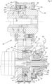
- the clamping device shown and labeled 1 serves to actuate a power chuck 5 arranged on a machine tool 2, by means of which radially adjustable clamping jaws 6 a workpiece 10 to be machined is clamped in the power chuck 5.
- the clamping jaws 6 of the power chuck 5 can be actuated via deflection levers 8 by an axially adjustable two-part pull rod 7, 7', which is in drive connection with a switchable electric drive motor 11 via a motion converter 15.
- the rotary adjustment movements of the drive motor 11 are converted into axial feed movements of the pull rod 7, 7' by means of the movement converter 15.
- An electric motor 4 acts on the machine spindle 3 and can be used to drive the machine tool 2 .
- the tensioning device 1 has a housing 17 in which the movement converter 15 and an energy accumulator 16 formed by spring assemblies 20 and 20' are accommodated.
- On the machine tool 2 side facing the housing 17 is provided with a protruding web on which a flange is attached.
- the flange is attached to a further flange 9 formed on the machine spindle 3 with the aid of screws.
- the drive energy is supplied to the motion converter 15 via intermediate members 19 which are in drive connection with a spindle nut 18 .
- the spindle nut 18, on which the spring assemblies 20 and 20' of the force accumulator 16 act during clamping processes the rotational movements introduced are transmitted to the drawbar 7' and thereby converted into axial feed movements depending on the direction of rotation.
- the drive motor 11 is in drive connection with the clamping device 1 via two drive trains 21 and 31 .
- a support hub 13 is arranged on the rotor shaft 12 of the drive motor 11 in a rotationally fixed manner with the aid of a splined connection 25 and is secured to the rotor shaft 12 by means of a screw 14 .
- Belt pulleys 22 and 32 of two belt drives 21' and 31', which form the drive trains 21 and 31, are arranged on the supporting hub 13.
- One of the belt pulleys, namely the belt pulley 22 is in turn connected to the supporting hub 13 in a rotationally fixed manner by means of a splined connection 26 .
- the belt pulley 32 of the belt drive 31' is rotatably mounted on the support hub 13.
- the pulleys 22 and 32 are drivingly connected to pulleys 23 and 33 , which are coupled to drive members of the tensioning device 1 , via toothed belts or drive belts 24 and 34 .
- the belt pulley 23 is rotatably mounted on a hollow shaft 27 by means of roller bearings 28 and is connected to the intermediate members 19 via a toothing 30 provided on a shoulder 29 .
- the pulley 33 on the other hand, is firmly attached to the hollow shaft 27 with the aid of screws 38.
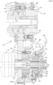
- the belt pulley 32 of the belt drive 31 is rotatably supported on the supporting hub 13 by means of a roller bearing 36 and a supporting disk 35 .
- the belt pulley 32 is secured to the support pulley 35 by means of screws 37 .
- the pulley 32 is connected to an intermediate link 44 connected, namely how this particular the figures 2 and 3 can be seen, with the help of sleeves 48, which are inserted into bores 47 worked into the pulley 32, and screws 49, which pass through the sleeve 48 and by which the intermediate member 44 is connected to a toothed pulley 46 arranged between the two pulleys 32 and 22 is.
- the intermediate member 44 is arranged to be displaceable on the support hub 13 via a sliding bearing 45 .
- a servo device 51 or 61 is used to actuate the intermediate member 44 Figure 1 to 3
- the exemplary embodiment shown consists of a cylinder 52 which is stationary and rotatable on the support hub 13 by means of a bearing 59 and a piston 53 which is inserted in this cylinder and is axially displaceable and can be acted upon on both sides by pressure medium.
- a control valve 60 can be used to alternately supply pressure medium from a pressure medium supply line 60' to the pressure chambers 54 or 55 in order to move the intermediate member 44 to the left or right, depending on the operating state.
- the pressure piston 53 is rotatably arranged on the intermediate member 44 by means of a roller bearing 56 , it is firmly connected to the intermediate member 44 in the axial direction by means of a molded nose 57 and a snap ring 58 .
- the intermediate member 44 can be mechanically coupled via a gear coupling 41 to the belt pulley 22 of the belt drive 21'.
- toothing 42 is attached to the side surface facing intermediate member 44, and toothed disc 46, which is firmly connected to intermediate member 44, is equipped with counter-toothing 43, which can be inserted into toothing 42 with the aid of servo device 51.
- the two belt pulleys 22 and 32 are firmly connected to one another and the clamping device 1 is blocked, so that machining processes can be carried out.
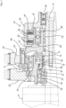
- the toothed disk 46 and the intermediate element 44 firmly connected to it are automatically axial by means of blind bores 50' worked into the intermediate element 44 and blind bores 50" provided in the toothed disk 46 If the servo device 51 fails, the toothing 43 snaps into the toothing 42 by means of an axial displacement to the left, triggered by the force of the springs 50, so that the two belt drives 21' and 31' are blocked.
- the servo device 61 can also, as in the figures 4 and 5 shown, consist of two magnetic coils 63 and 64 which are inserted in a housing 62 supported on the supporting hub 13 by means of a roller bearing 69 and which cooperate with an axially displaceable armature 65 .
- the armature 65 is in turn coupled by means of integrally formed lugs 66 and 67 to a roller bearing 68 which is inserted into the intermediate member 44 mounted on the support hub 13 by means of roller bearings 70 .
- the toothed clutch 41 is thus opened ( figure 4 ).
- the gear coupling 41 is closed by an axial displacement of the armature 65 to the left.
- the belt pulley 22 ′ is also arranged rotatably on the supporting hub 13 by means of a roller bearing 76 .
- a sliding sleeve 71 that can be actuated by the intermediate piece 44 is provided, which is non-rotatably connected to the supporting hub 13 by means of a wedge connection 72 and can be coupled to an intermediate member 75 by axial displacement.
- the intermediate piece 75, on which the pulley 32 is supported with the aid of roller bearings 80, is firmly connected to the pulley 22' by means of screws 79.
- FIG 1 the operating position of the clamping device 1 is shown during operations.
- the workpiece 10 clamped in the power chuck 5 can be machined according to the specifications.
- the two belt drives 21' and 31' are connected to one another via the toothed coupling 41 and rotate together with the support hub 13.
- the connection between the two belt drives 21' and 31' must be released with the aid of the servo device 51 by opening the toothed clutch 41 and energy is to be supplied to the tensioning device 1 via the belt drive 21' with the aid of the drive motor 11.
- the belt pulley 22 is rotated and also the threaded nut 18 connected to it via intermediate members 19, so that the pull rod 7' is displaced axially by this and the clamping jaws 6 are adjusted inwards or outwards.
- the workpiece 10 can thus be removed or another workpiece can be used. After completion of this work process is again by means of the servo device 51 the in figure 1 to produce the operating state shown.
- the pulleys 23 and 33 are each assigned a coupling device 91 or 91'.
- the coupling devices 91 and 91' each consist of slightly axially displaceable thrust washers 92 and 93, which are arranged on the outer sides of the pulleys 23 and 33, and locking bolts 95, which can be coupled to the opposite pulley 33 or 23, respectively.
- the thrust washers 92 and 93 are each slidably mounted on pins 94 and lie on the toothed or drive belts 24 and 34 on the side.
- the thrust washer 92 or 93 is pushed in the direction of the belt pulleys 23 or 33 by the force of springs 97, which act on the locking bolts 95 and to which the thrust washers 92, 93 are connected by means of screws 98, so that the locking bolts 95 engage in associated recesses 96 provided on the opposite pulleys 33 and 23, respectively, so that the two pulleys 23 and 33 are thus firmly connected to one another. In this case, the clamping device 1 is again blocked.
- the servo device 51 is associated with a displacement sensor 81 by means which the adjustment of the intermediate member 44 is to be monitored.
- the drive motor 11 is equipped with a sensor 82 for monitoring the motor speed, which is connected directly to a control unit 85 upstream of the drive motor 11 .
- the pull rod 7 interacts with a sensor 83, by means of which its adjustment path can be controlled.
- the energy accumulator 16 is also equipped with a sensor 84 in order to be able to detect the given clamping force of the power chuck 5.
Description
Die Erfindung bezieht sich eine Spanneinrichtung, insbesondere für Werkzeugmaschinen, die beispielsweise mit einem Kraftspannfutter zur Halterung eines Werkstückes versehen und dessen Spannbacken mittels der Spanneinrichtung über eine axial verstellbare Zugstange als Betätigungsglied verstellbar sind, wobei die Spanneinrichtung einen umschaltbaren elektrischen Antriebsmotor zum Auslösen von Spannbewegungen, der über Antriebsstränge mit der Spanneinrichtung verbunden ist, einen Bewegungswandler zur Umsetzung der Verstellbewegungen der Rotorwelle des Antriebsmotors in die zur Betätigung der Spannbacken erforderlichen axialen Verstellbewegungen der Zugstange sowie einen Kraftspeicher zur Aufrechterhaltung der Spannkraft aufweist.The invention relates to a clamping device, in particular for machine tools, which is provided, for example, with a power chuck for holding a workpiece and whose clamping jaws can be adjusted by means of the clamping device via an axially adjustable drawbar as an actuating element, the clamping device having a switchable electric drive motor for triggering clamping movements, the is connected to the clamping device via drive trains, has a movement converter for converting the adjustment movements of the rotor shaft of the drive motor into the axial adjustment movements of the pull rod required to actuate the clamping jaws, and an energy accumulator for maintaining the clamping force.
Die
Nachteilig an dieser Spannvorrichtung ist, dass kein Kraftspeicher zur Aufrechterhaltung der Spannkraft vorhanden ist.The disadvantage of this clamping device is that there is no energy store to maintain the clamping force.
Auch die
Aufgabe der Erfindung ist es daher, die Spanneinrichtung der Eingangs genannten Gattung in der Weise auszubilden, dass der Steuerungs- und Bauaufwand äußerst gering gehalten werden kann und mit Hilfe einer serienmäßigen NC-Steuerung zu bewerkstelligen ist. Dadurch soll die Störanfälligkeit auf ein Minimum reduziert werden, so dass ein sicherer Betrieb der Spanneinrichtung über einen längeren Zeitraum sichergestellt ist. Des Weiteren soll erreicht werden, dass keine in einem Ölbad anzuordnenden Zahnradsätze erforderlich sind und dass im Betrieb der Antriebsmotor auf einfache Weise von der Spanneinrichtung abzukoppeln ist, um den Energieaufwand gering zu halten. Auch soll bei einer Beschädigung von Bauteilen zuverlässig eine Blockierung selbsttätig ausgelöst werden, so dass die Unfallgefahr gemindert wird.The object of the invention is therefore to design the clamping device of the type mentioned at the outset in such a way that the control and construction costs can be kept extremely low and can be accomplished with the aid of a standard NC control. This is intended to reduce the susceptibility to faults to a minimum, so that safe operation of the clamping device is ensured over a longer period of time. Furthermore, it should be achieved that no gear sets to be arranged in an oil bath are required and that during operation the drive motor is easy to decouple from the clamping device in order to keep the energy consumption low. In the event of damage to components, a blocking should also be reliably triggered automatically, so that the risk of accidents is reduced.
Gemäß der Erfindung wird diese Aufgabe durch eine Spanneinrichtung gemäß dem Anspruch 1 oder gemäß dem Anspruch 6 gelöst. Bei einer Spanneinrichtung gemäß dem Anspruch 1 sind die beiden Antriebsstränge aus einem ersten und einem zweiten jeweils aus zwei Riemenscheiben und einem über diese geführten Zahn- oder Treibriemen bestehenden Riementrieb gebildet, wobei auf der Rotorwelle des Antriebsmotors eine Tragnabe drehfest angeordnet ist, auf der die Riemenscheibe des ersten Riementriebes drehfest und die Riemenscheibe des zweiten Riementriebes drehbar gelagert sind, wobei in Spannstellung der Spanneinrichtung die beiden auf der Tragnabe angeordneten Riemenscheiben mit Hilfe einer Servo-Einrichtung miteinander koppelbar sind.According to the invention, this object is achieved by a clamping device according to claim 1 or according to
Die drehbar auf der Tragnabe gelagerte Riemenscheibe ist mittels eines axial verschiebbaren Zwischengliedes, das mit der Servo-Einrichtung verbunden ist, mit der ortsfest angeordneten Riemenscheibe zu koppeln, wobei das Zwischenglied mit einer zwischen den beiden Riemenscheiben angeordneten Zahnscheibe fest verbunden ist, die eine Verzahnung aufweist, die mit einer an der ortsfest angeordneten Riemenscheibe angebrachten Gegenverzahnung zusammenwirkt.The pulley, which is rotatably mounted on the support hub, is to be coupled to the stationary pulley by means of an axially displaceable intermediate member, which is connected to the servo device, the intermediate member being firmly connected to a toothed pulley which is arranged between the two pulleys and has teeth , which interacts with a counter-toothing attached to the stationary pulley.
Um bei einem eventuellen Ausfall der Servo-Einrichtung eine Sicherung zu schaffen, indem selbsttätig über das Zwischenglied eine Blockierung bewerkstelligt wird, ist es bevorzugt angezeigt, das Zwischenglied unmittelbar oder über die an diesem angebrachte Zahnscheibe durch die Kraft von Federn in axialer Richtung an der Riemenscheibe des zweiten Riementriebes abzustützen, so dass die beiden Riemenscheiben fest miteinander verbunden sind und die Spanneinrichtung blockiert ist.In order to have a backup in the event of a failure of the servo device by automatically causing a blockage via the intermediate member, it is preferable to support the intermediate member directly or via the toothed disc attached to it by the force of springs in the axial direction on the pulley of the second belt drive, so that the two pulleys are fixed to one another are connected and the clamping device is blocked.
Die Servo-Einrichtung kann in einfacher Ausgestaltung aus einem in einem Zylinder eingesetzten und beidseitig von Druckmitteln beaufschlagbaren Druckkolben gebildet sein, der drehbar auf dem Zwischenglied gelagert und mit diesem in beiden axialen Richtungen gekoppelt ist. Es ist aber auch möglich, die Servo-Einrichtung aus zwei ortsfest angeordneten Magnetspulen und einem axial verschiebbaren Anker zu bilden, der drehbar auf dem Zwischenglied gelagert und mit diesem in beiden axialen Richtungen gekoppelt ist. Der Servo-Einrichtung kann hierbei ein Wegsensor zur Überwachung des Verstellweges des Zwischengliedes zugeordnet werden.In a simple configuration, the servo device can be formed from a pressure piston which is inserted in a cylinder and can be acted upon on both sides by pressure medium, which is rotatably mounted on the intermediate member and is coupled to it in both axial directions. However, it is also possible to form the servo device from two stationarily arranged magnetic coils and an axially displaceable armature which is rotatably mounted on the intermediate element and is coupled to it in both axial directions. A travel sensor for monitoring the adjustment travel of the connecting link can be assigned to the servo device.
Bei der Spanneinrichtung des Anspruchs 6 ist die Riemenscheibe des ersten Riementriebes drehbar auf der Tragnabe gelagert werden. In diesem Fall ist zur drehfesten Verbindung der Riemenscheibe mit der Tragnabe eine Schiebemuffe vorzusehen, die drehfest mit der Tragnabe verbunden und mit Hilfe der Servo-Einrichtung, vorzugsweise über eine Zahnkupplung, mit der Riemenscheibe koppelbar ist.In the tensioning device of
Bei einer lösbaren Verbindung der ersten Riemenscheibe mit der Tragnabe ist es bevorzugt anzeigt, als Antriebsmotor einen Wechselstrom- oder Gleichstrommotor vorzusehen.In the case of a detachable connection of the first belt pulley to the support hub, it is preferable to provide an AC or DC motor as the drive motor.
Bevorzugt ist es des Weiteren, dem Antriebsmotor einen Sensor zur Bestimmung und/oder Überwachung der Abtriebsdrehzahl zuzuordnen.Furthermore, it is preferred to assign a sensor for determining and/or monitoring the output speed to the drive motor.
Bevorzugt ist ferner angebracht, eine oder beide der auf den Antriebsgliedern der Spanneinrichtung angeordneten bzw. mit diesen verbundenen Riemenscheiben jeweils mit einer bei einer Beschädigung eines Zahn- oder Treibriemens selbsttätig wirksamen Koppelvorrichtung auszustatten, mittels der die beiden Riemenscheiben formschlüssig miteinander verbindbar sind.It is also preferred to equip one or both of the pulleys arranged on the drive members of the tensioning device or connected to them with a coupling device that is automatically effective in the event of damage to a toothed belt or drive belt, by means of which the two Pulleys are positively connected to each other.
Dies kann in der Weise bewerkstelligt werden, indem die Koppelvorrichtungen jeweils aus zwei auf den Außenseiten der Riemenscheiben begrenzt axial verschiebbar angeordneten Anlaufscheiben und einem oder mehreren in eine der Anlaufscheiben eingesetzten, axial verschiebbaren Rastbolzen gebildet werden, die an der Anlaufscheibe abgestützt und durch die Kraft von Federn in zugeordnete in der gegenüberliegenden Riemenscheibe vorgesehene Ausnehmungen einführbar sind.This can be accomplished in such a way that the coupling devices are each formed from two thrust washers arranged on the outside of the belt pulleys so that they can be displaced axially to a limited extent and one or more axially displaceable locking bolts inserted into one of the thrust washers, which are supported on the thrust washer and are actuated by the force of Springs can be inserted into associated recesses provided in the opposite pulley.
Wird eine Spanneinrichtung gemäß der Erfindung ausgebildet, indem die Antriebsstränge als Riementriebe ausgebildet werden und auf der Rotorwelle des Antriebsmotors eine Tragnabe fest angeordnet wird, die mittels einer Servo-Einrichtung kuppelbare Riemenscheiben trägt, so ist es möglich, den Antriebsmotor und die Servo-Einrichtung mit Hilfe vorhandener NC-Steuerungen an die jeweiligen Gegebenheiten problemlos anzupassen, so dass ein sicherer und störungsfreier Betrieb über einen langen Zeitraum gewährleistet ist. Außerdem ist sichergestellt, dass zum Beispiel bei Bruch eines Zahn- oder Treibriemens sofort und selbsttätig eine Blockierung der mit den Antriebsgliedern der Spanneinrichtung verbundenen Riemenscheiben erfolgt.If a tensioning device is designed according to the invention, in which the drive trains are designed as belt drives and a supporting hub is firmly arranged on the rotor shaft of the drive motor, which hub carries belt pulleys that can be coupled by means of a servo device, it is possible to use the drive motor and the servo device with Easily adapted to the respective circumstances with the help of existing NC controls, so that safe and trouble-free operation is guaranteed over a long period of time. It is also ensured that, for example, if a toothed belt or drive belt breaks, the pulleys connected to the drive members of the tensioning device are blocked immediately and automatically.
Der Antrieb der Spanneinrichtung ist somit ohne Zwischenschaltung eines Unter- oder Übersetzungsgetriebes und ohne aufwendige Steuerungen gewährleistet. Der Bauaufwand ist demnach gering. Des Weiteren kann gegebenenfalls ein Wechselstrom- oder Gleichstrommotor eingesetzt werden, der im Betrieb auch stillgesetzt werden kann. Es ist somit nicht nur ein geringer Fertigungsaufwand erforderlich, um eine elektrische Spanneinrichtung zu schaffen, sondern es werden auch deren Betriebskosten gering gehalten, und es ist ein störungsfreier Betrieb stets gegeben.The drive of the clamping device is thus guaranteed without the interposition of a reduction or transmission gear and without complex controls. The construction cost is therefore low. Furthermore, if necessary, an AC or DC motor can be used, which can also be shut down during operation. It is therefore not only a small manufacturing effort required to create an electrical clamping device, but it also keeps its operating costs low, and there is always trouble-free operation.
In der Zeichnung sind zwei Ausführungsbeispiele der erfindungsgemäßen Spanneinrichtung dargestellt und nachfolgend im Einzelner erläutert. Hierbei zeigt:
-
Figur 1 ein erstes Ausführungsbeispiel der Spanneinrichtung einschließlich des Antriebsmotor, in einem Längsschnitt, -
Figur 2
einen Ausschnitt ausFigur 1 , in einer vergrößerten Wiedergabe, -
Figur 3
den Ausschnitt nachFigur 2 , in einer andersartigen Betriebsstellung, und -
Figuren 45
die Verbindung der beiden drehbar auf der Tragnabe gelagerten Riemenscheiben mit Hilfe von Elektrokupplungen gemäß einem zweiten Ausführungsbeispiel der Spanneinrichtung, in unterschiedlichen Betriebsstellungen.
-
figure 1 a first embodiment of the clamping device including the drive motor, in a longitudinal section, -
figure 2
a snippetfigure 1 , in an enlarged view, -
figure 3
the cutoutfigure 2 , in a different operating position, and -
figures 4 and5
the connection of the two pulleys rotatably mounted on the support hub by means of electric clutches according to a second embodiment of the tensioning device, in different operating positions.
Die in
Die Spanneinrichtung 1 weist ein Gehäuse 17 auf, in dem der Bewegungswandler 15 und ein durch Federpakete 20 und 20' gebildeter Kraftspeicher 16 untergebracht sind. Auf der der Werkzeugmaschine 2 zugewandten Seite ist das Gehäuse 17 mit einem abstehenden Steg versehen, an dem ein Flansch befestigt ist. Mit Hilfe von Schrauben ist der Flansch an einem an der Maschinenspindel 3 angeformten weiteren Flansch 9 angebracht.The tensioning device 1 has a
Dem Bewegungswandler 15 wird die Antriebsenergie über Zwischenglieder 19 zugeführt, die mit einer Spindelmutter 18 in Triebverbindung stehen. Mittels der Spindelmutter 18, auf die die Federpakete 20 und 20' des Kraftspeichers 16 bei Spannvorgängen einwirken, werden die eingeleiteten rotatorischen Bewegungen auf die Zugstange 7' übertragen und dabei in axiale Zustellbewegungen je nach Drehrichtung umgewandelt.The drive energy is supplied to the motion converter 15 via
Der Antriebsmotor 11 steht über zwei Antriebsstränge 21 und 31 mit der Spanneinrichtung 1 in Triebverbindung. Um dies zu bewerkstelligen, ist auf der Rotorwelle 12 des Antriebsmotors 11 drehfest mit Hilfe einer Keilverbindung 25 eine Tragnabe 13 angeordnet, die mittels einer Schraube 14 an der Rotorwelle 12 gesichert ist. Auf der Tragnabe 13 sind Riemenscheiben 22 und 32 zweier Riementriebe 21' und 31' angeordnet, die die Antriebsstränge 21 und 31 bilden. Eine der Riemenscheiben, nämlich die Riemenscheibe 22, ist hierbei wiederum mittels einer Keilverbindung 26 drehfest mit der Tragnabe 13 verbunden. Die Riemenscheibe 32 des Riementriebes 31' ist dagegen drehbar auf der Tragnabe 13 gelagert. Über Zahn- oder Treibriemen 24 bzw. 34 sind die Riemenscheiben 22 bzw. 32 mit Riemenscheiben 23 bzw. 33 trieblich verbunden, die an Antriebsgliedern der Spanneinrichtung 1 angekoppelt sind. Die Riemenscheibe 23 ist hierbei mittels Wälzlager 28 drehbar auf einer Hohlwelle 27 gelagert und über eine an einem Ansatz 29 vorgesehene Verzahnung 30 mit den Zwischengliedern 19 verbunden. Die Riemenscheibe 33 dagegen ist mit Hilfe von Schrauben 38 fest an der Hohlwelle 27 angebracht.The
Die Riemenscheibe 32 des Riementriebes 31 ist mittels eines Wälzlagers 36 und einer Tragscheibe 35 drehbar auf der Tragnabe 13 abgestützt. Mittels Schrauben 37 ist hierbei die Riemenscheibe 32 an der Tragscheibe 35 gesichert. Außerdem ist die Riemenscheibe 32 mit einem Zwischenglied 44 verbunden, und zwar, wie dies insbesondere den
Zur Betätigung des Zwischengliedes 44 dient eine Servo-Einrichtung 51 bzw. 61, die bei dem in
Der Druckkolben 53 ist mittels eines Wälzlagers 56 zwar drehbar auf dem Zwischenglied 44 angeordnet, mittels einer angeformten Nase 57 und einem Sprengring 58 aber in axialer Richtung fest mit dem Zwischenglied 44 verbunden.Although the
Das Zwischenglied 44 ist über eine Zahnkupplung 41 mit der Riemenscheibe 22 des Riementriebes 21' mechanisch koppelbar. Dazu ist an dieser auf der dem Zwischenglied 44 zugewandten Seitenfläche eine Verzahnung 42 angebracht, und die mit dem Zwischenglied 44 fest verbundene Zahnscheibe 46 ist mit einer Gegenzahnung 43 ausgestattet, die mit Hilfe der Servo-Einrichtung 51 in die Verzahnung 42 einführbar ist. In diesem Betriebszustand sind die beiden Riemenscheiben 22 und 32 fest miteinander verbunden und die Spanneinrichtung 1 ist blockiert, so dass Bearbeitungsvorgänge ausgeführt werden können.The
Um bei einem eventuell Ausfall der Servo-Einrichtung 51 einen Betriebsunfall zu vermeiden, ist die Zahnscheibe 46 und das mit dieser fest verbundene Zwischenglied 44 mittels in das Zwischenglied 44 eingearbeitete Sacklochbohrungen 50' und in der Zahnscheibe 46 vorgesehene Sacklochbohrungen 50" eingesetzte Druckfedern 50 selbsttätig axial verschiebbar. Bei einem Ausfall der Servo-Einrichtung 51 rastet somit durch eine Axialverschiebung nach links, ausgelöst durch die Kraft der Federn 50, die Verzahnung 43 in die Verzahnung 42 ein, so dass die beiden Riementriebe 21' und 31' blockiert sind.In order to avoid an operational accident in the event of a failure of the
Die Servo-Einrichtung 61 kann aber auch, wie dies in den
Bei der Ausgestaltung nach den
Bei Erregung der Magnetspule 64 (
In
Soll jedoch eine Verstellung der Spannbacken 6 vorgenommen werden, um das Werkstück 10 auszuspannen und gegebenenfalls ein anderes Werkstück einzuspannen, so ist mit Hilfe der Servo-Einrichtung 51 die Verbindung zwischen den beiden Riementrieben 21' und 31' zu lösen, indem die Zahnkupplung 41 geöffnet wird, und es ist über den Riementrieb 21' der Spanneinrichtung 1 mit Hilfe des Antriebsmotors 11 Energie zuzuführen. Die Riemenscheibe 22 wird dabei verdreht und auch die über Zwischenglieder 19 mit dieser verbundene Gewindemutter 18, so dass durch diese die Zugstange 7' axial verschoben wird und die Spannbacken 6 nach innen oder außen verstellt werden. Das Werkstück 10 kann somit entfernt oder ein anderes Werkstück kann eingesetzt werden. Nach Beendigung dieses Arbeitsvorganges ist mittels der Servo-Einrichtung 51 wiederum der in
Die Ausgestaltung nach den
Um bei einem eventuellen Bruch eines der Zahn- oder Treibriemen 24 oder 34 eine Blockade der Antriebsstränge 21 und 31 zu bewerkstelligen, ist, wie dies in den
Bei einem Bruch eines der Zahn- oder Treibriemen 24 oder 34, wie dies in
Zur Überwachung der einzelnen Betriebszustände sind verschiedene Sensoren vorgesehen. Der Servo-Einrichtung 51 ist ein Wegsensor 81 zugeordnet, mittels dem der Verstellweg des Zwischengliedes 44 zu überwachen ist. Des Weiteren ist der Antriebsmotor 11 mit einem Sensor 82 zur Kontrolle der Motordrehzahl ausgestattet, der unmittelbar an ein dem Antriebsmotor 11 vorgeschaltetes Steuergerät 85 angeschlossen ist. Des Weiteren wirkt die Zugstange 7 mit einem Sensor 83 zusammen, mittels dem deren Verstellweg kontrolliert werden kann. Auch der Kraftspeicher 16 ist mit einem Sensor 84 ausgestattet, um die jeweils gegebene Spannkraft des Kraftspannfutters 5 erkennen zu können.Various sensors are provided to monitor the individual operating states. The
Claims (10)
- Clamping device (1), in particular for machine tools (2) which are provided, for example with a heavy-duty chuck (5) for holding a workpiece (10) and the clamping jaws (6) of which can be adjusted by means of the clamping device (1) via an axially adjustable connecting rod (7, 7') as the actuating element, wherein the clamping device (1) has a reversible electric drive motor (11) to trigger clamping movements, two drive trains (21, 31) connected to the drive motor (11), and a motion converter (15) to convert the adjusting movements of the rotor shaft (12) of the drive motor (11) into the axial adjusting movements of the connecting rod (7, 7') required to actuate the clamping jaws (6), wherein the two drive trains (21, 31) are formed from a first and a second belt drive (21', 31') consisting respectively of two pulleys (22, 23 or 32, 33) and a toothed belt or driving belt (24, 34) guided over the latter, wherein a supporting hub (13) is arranged to be resistant to rotation on the rotor shaft (12) of the drive motor (11), on which supporting hub (13) the pulley (22) of the first belt drive (21') is mounted to be resistant to rotation and the pulley (32) of the second belt drive (31') is mounted to be rotatable, wherein in the clamping position of the clamping device (1), the two pulleys (32, 32) arranged on the supporting hub (13) can be coupled to one another with the aid of a servo device (51), characterised in that the clamping device (1) has an accumulator (16) to maintain the clamping force, and in that the pulley (32) mounted to be rotatable on the supporting hub (13) can be connected to the pulley (22) arranged to be resistant to rotation by means of an axially displaceable intermediate element (44), which can be actuated by means of the servo device (51), and in that the intermediate element (44) is firmly connected to a toothed disc (46) arranged between the two pulleys (22, 32) which has toothing (43) which cooperates with counter-toothing (42) attached to the pulley (22) arranged to be resistant to rotation.
- Clamping device according to claim 1, characterised in that the intermediate element (44) is supported directly or via the toothed disc (46) attached to the latter by the force of springs (50) in axial direction on the pulley (32) of the second belt drive (31').
- Clamping device according to claim 1 or 2, characterised in that the servo device (51) is formed from a pressure piston (54) inserted in a cylinder (53) and impacted on both sides by pressure means and which is mounted to be rotatable on the intermediate element (44) and coupled to the latter in both axial directions.
- Clamping device according to claim 1 or 2, characterised in that the servo device (61) is formed from two magnetic coils (63, 64) arranged to be fixed and an axially displaceable anchor (65) which is mounted to be rotatable on the intermediate element (44) and coupled to the latter in both axial directions.
- Clamping device according to one of claims 3 or 4, characterised in that a displacement sensor (81) to monitor the adjustment path of the intermediate element (44) is assigned to the servo device (51).
- Clamping device (1), in particular for machine tools (2) which are provided, for example with a heavy-duty chuck (5) for holding a workpiece (10) and the clamping jaws (6) of which can be adjusted by means of the clamping device (1) via an axially adjustable connecting rod (7, 7') as the actuating element, wherein the clamping device (1) has a reversible electric drive motor (11) to trigger clamping movements, two drive trains (21, 31) connected to the drive motor (11), and a motion converter (15) to convert the adjusting movements of the rotor shaft (12) of the drive motor (11) into the axial adjusting movements of the connecting rod (7, 7') required to actuate the clamping jaws (6), wherein the two drive trains (21, 31) are formed from a first and a second belt drive (21', 31') consisting respectively of two pulleys (22', 23 or 32, 33) and a toothed belt or driving belt (24, 34) guided over the latter, wherein a supporting hub (13) is arranged to be resistant to rotation on the rotor shaft (12) of the drive motor (11), on which supporting hub (13) the pulley (22') of the first belt drive (21') and the pulley (32) of the second belt drive (31') are mounted, wherein in the clamping position of the clamping device (1), the two pulleys (22', 32) arranged on the supporting hub (13) can be coupled to one another with the aid of a servo device (61) and of an intermediate element (44) axially displaceable due to the latter, characterised in that the clamping device has an accumulator (16) to maintain the clamping force, in that the pulley (22') of the first belt drive (21') and the pulley (32) of the second belt drive (31') are mounted to be rotatable on the supporting hub (13), in that the intermediate element (44) is firmly connected to a toothed disc (46) arranged between the two pulleys (22', 32) which has toothing (43) which cooperates with counter-toothing (42) attached to the pulley (22') of the first belt drive (21') and in that a sliding sleeve (71), which is connected to the supporting hub (13) to be resistant to rotation and can be coupled to the pulley (22) with the aid of the servo device (61), preferably via a toothed coupling (77, 78), is provided for rotation-resistant connection of the pulley (22) of the first belt drive (21') to the supporting hub (44).
- Clamping device according to claim 6, characterised in that for releasable connection of the pulley (22') of the first belt drive (21') to the supporting hub (13), an alternating-current motor or direct-current motor is provided as the drive motor (11).
- Clamping device according to one or more of claims 1 to 7, characterised in that a sensor (82) for determining and/or monitoring the output speed is assigned to the drive motor (11).
- Clamping device according to one or more of claims 1 to 8, characterised in that one or both of the pulleys (23, 33) arranged on the drive elements (27) of the clamping device (1) or connected to the latter are provided respectively with an automatically active coupling device (91, 91') when there is damage to a toothed belt or driving belt (24 or 34), by means of which the two pulleys (23, 33) can be positively connected to one another.
- Clamping device according to claim 9, characterised in that the coupling device (91, 91') are formed respectively from two thrust washers (92, 93) arranged on the outer sides of the pulleys (23 or 33) to be axially displaceable to a limited extent and one or more axially displaceable locking bolts (93) inserted in one of the thrust washers (92) and which are supported on the thrust washers (92) and can be introduced by the force of springs (97) into assigned recesses (96) provided in the opposite pulley (33 or 23).
Priority Applications (1)
| Application Number | Priority Date | Filing Date | Title |
|---|---|---|---|
| EP15179801.4A EP3127640B1 (en) | 2015-08-05 | 2015-08-05 | Clamping device |
Applications Claiming Priority (1)
| Application Number | Priority Date | Filing Date | Title |
|---|---|---|---|
| EP15179801.4A EP3127640B1 (en) | 2015-08-05 | 2015-08-05 | Clamping device |
Publications (2)
| Publication Number | Publication Date |
|---|---|
| EP3127640A1 EP3127640A1 (en) | 2017-02-08 |
| EP3127640B1 true EP3127640B1 (en) | 2023-02-22 |
Family
ID=53783120
Family Applications (1)
| Application Number | Title | Priority Date | Filing Date |
|---|---|---|---|
| EP15179801.4A Active EP3127640B1 (en) | 2015-08-05 | 2015-08-05 | Clamping device |
Country Status (1)
| Country | Link |
|---|---|
| EP (1) | EP3127640B1 (en) |
Families Citing this family (1)
| Publication number | Priority date | Publication date | Assignee | Title |
|---|---|---|---|---|
| DE102020112170A1 (en) | 2020-05-06 | 2021-11-11 | Röhm Gmbh | Electric actuation unit for machine tools |
Family Cites Families (6)
| Publication number | Priority date | Publication date | Assignee | Title |
|---|---|---|---|---|
| JP4917398B2 (en) | 2006-09-27 | 2012-04-18 | オークマ株式会社 | Electric chuck opening and closing device |
| EP2218531B1 (en) * | 2009-02-11 | 2012-12-05 | Karl Hiestand | Clamping device for machine tools |
| EP2283955A1 (en) * | 2009-08-13 | 2011-02-16 | Karl Hiestand | Clamping device for machine tools |
| EP2295176B1 (en) * | 2009-09-12 | 2018-11-07 | Karl Hiestand | Tensioning assembly |
| EP2548681B1 (en) * | 2011-07-19 | 2017-04-05 | Karl Hiestand | Clamping device for machine tools |
| DE102012011675B4 (en) * | 2012-06-14 | 2014-01-09 | Forkardt Deutschland Gmbh | Axialzugvorrichtung and machine tool with a Axialzugvorrichtung |
-
2015
- 2015-08-05 EP EP15179801.4A patent/EP3127640B1/en active Active
Also Published As
| Publication number | Publication date |
|---|---|
| EP3127640A1 (en) | 2017-02-08 |
Similar Documents
| Publication | Publication Date | Title |
|---|---|---|
| EP2311589B1 (en) | Tensioning assembly | |
| EP2384839B1 (en) | Clamping device | |
| EP2868410B1 (en) | Clamping device for machine tools | |
| EP3040144B1 (en) | Clamping device | |
| EP1637260A1 (en) | Clamping device for machine tool | |
| EP3362215B1 (en) | Clamping device | |
| EP2796233A1 (en) | Coupling device | |
| EP2103368A1 (en) | Clamping device for machine tools | |
| EP2218531B1 (en) | Clamping device for machine tools | |
| EP1728574A1 (en) | Clamping device for a machine tool | |
| EP3059036A1 (en) | Collet chuck with electric motors | |
| WO2006136136A1 (en) | Spindle comprising a tension rod and a coupling device | |
| EP0436769B1 (en) | Device for generating a clamping force in a clamping device | |
| EP3127640B1 (en) | Clamping device | |
| EP2363223B1 (en) | Clamping device for machine tools | |
| EP2724801B1 (en) | Tensioning assembly | |
| EP2283955A1 (en) | Clamping device for machine tools | |
| EP3175942B1 (en) | Clamping device | |
| EP1237704A1 (en) | Device and method for carrying out a two-stage linear movement | |
| DE102019105643A1 (en) | Clamping device | |
| EP2837450B1 (en) | Clamping device | |
| DE2233636C3 (en) | Device for controlling the pressure medium supply to clamping cylinders or power-operated front end chucks | |
| EP3448627B1 (en) | Motorized joint for a programmable moving machine | |
| DE3546252A1 (en) | Machine tool and its method of operation | |
| EP0823967B1 (en) | Safety device for an electro-hydraulic drive unit |
Legal Events
| Date | Code | Title | Description |
|---|---|---|---|
| PUAI | Public reference made under article 153(3) epc to a published international application that has entered the european phase |
Free format text: ORIGINAL CODE: 0009012 |
|
| STAA | Information on the status of an ep patent application or granted ep patent |
Free format text: STATUS: THE APPLICATION HAS BEEN PUBLISHED |
|
| AK | Designated contracting states |
Kind code of ref document: A1 Designated state(s): AL AT BE BG CH CY CZ DE DK EE ES FI FR GB GR HR HU IE IS IT LI LT LU LV MC MK MT NL NO PL PT RO RS SE SI SK SM TR |
|
| AX | Request for extension of the european patent |
Extension state: BA ME |
|
| STAA | Information on the status of an ep patent application or granted ep patent |
Free format text: STATUS: REQUEST FOR EXAMINATION WAS MADE |
|
| 17P | Request for examination filed |
Effective date: 20170412 |
|
| RBV | Designated contracting states (corrected) |
Designated state(s): AL AT BE BG CH CY CZ DE DK EE ES FI FR GB GR HR HU IE IS IT LI LT LU LV MC MK MT NL NO PL PT RO RS SE SI SK SM TR |
|
| STAA | Information on the status of an ep patent application or granted ep patent |
Free format text: STATUS: EXAMINATION IS IN PROGRESS |
|
| 17Q | First examination report despatched |
Effective date: 20200304 |
|
| STAA | Information on the status of an ep patent application or granted ep patent |
Free format text: STATUS: EXAMINATION IS IN PROGRESS |
|
| GRAP | Despatch of communication of intention to grant a patent |
Free format text: ORIGINAL CODE: EPIDOSNIGR1 |
|
| STAA | Information on the status of an ep patent application or granted ep patent |
Free format text: STATUS: GRANT OF PATENT IS INTENDED |
|
| INTG | Intention to grant announced |
Effective date: 20221004 |
|
| GRAS | Grant fee paid |
Free format text: ORIGINAL CODE: EPIDOSNIGR3 |
|
| GRAA | (expected) grant |
Free format text: ORIGINAL CODE: 0009210 |
|
| STAA | Information on the status of an ep patent application or granted ep patent |
Free format text: STATUS: THE PATENT HAS BEEN GRANTED |
|
| AK | Designated contracting states |
Kind code of ref document: B1 Designated state(s): AL AT BE BG CH CY CZ DE DK EE ES FI FR GB GR HR HU IE IS IT LI LT LU LV MC MK MT NL NO PL PT RO RS SE SI SK SM TR |
|
| REG | Reference to a national code |
Ref country code: GB Ref legal event code: FG4D Free format text: NOT ENGLISH |
|
| REG | Reference to a national code |
Ref country code: CH Ref legal event code: EP |
|
| REG | Reference to a national code |
Ref country code: DE Ref legal event code: R096 Ref document number: 502015016269 Country of ref document: DE |
|
| REG | Reference to a national code |
Ref country code: AT Ref legal event code: REF Ref document number: 1549192 Country of ref document: AT Kind code of ref document: T Effective date: 20230315 Ref country code: IE Ref legal event code: FG4D Free format text: LANGUAGE OF EP DOCUMENT: GERMAN |
|
| REG | Reference to a national code |
Ref country code: LT Ref legal event code: MG9D |
|
| REG | Reference to a national code |
Ref country code: NL Ref legal event code: MP Effective date: 20230222 |
|
| PG25 | Lapsed in a contracting state [announced via postgrant information from national office to epo] |
Ref country code: RS Free format text: LAPSE BECAUSE OF FAILURE TO SUBMIT A TRANSLATION OF THE DESCRIPTION OR TO PAY THE FEE WITHIN THE PRESCRIBED TIME-LIMIT Effective date: 20230222 Ref country code: PT Free format text: LAPSE BECAUSE OF FAILURE TO SUBMIT A TRANSLATION OF THE DESCRIPTION OR TO PAY THE FEE WITHIN THE PRESCRIBED TIME-LIMIT Effective date: 20230622 Ref country code: NO Free format text: LAPSE BECAUSE OF FAILURE TO SUBMIT A TRANSLATION OF THE DESCRIPTION OR TO PAY THE FEE WITHIN THE PRESCRIBED TIME-LIMIT Effective date: 20230522 Ref country code: NL Free format text: LAPSE BECAUSE OF FAILURE TO SUBMIT A TRANSLATION OF THE DESCRIPTION OR TO PAY THE FEE WITHIN THE PRESCRIBED TIME-LIMIT Effective date: 20230222 Ref country code: LV Free format text: LAPSE BECAUSE OF FAILURE TO SUBMIT A TRANSLATION OF THE DESCRIPTION OR TO PAY THE FEE WITHIN THE PRESCRIBED TIME-LIMIT Effective date: 20230222 Ref country code: LT Free format text: LAPSE BECAUSE OF FAILURE TO SUBMIT A TRANSLATION OF THE DESCRIPTION OR TO PAY THE FEE WITHIN THE PRESCRIBED TIME-LIMIT Effective date: 20230222 Ref country code: HR Free format text: LAPSE BECAUSE OF FAILURE TO SUBMIT A TRANSLATION OF THE DESCRIPTION OR TO PAY THE FEE WITHIN THE PRESCRIBED TIME-LIMIT Effective date: 20230222 Ref country code: ES Free format text: LAPSE BECAUSE OF FAILURE TO SUBMIT A TRANSLATION OF THE DESCRIPTION OR TO PAY THE FEE WITHIN THE PRESCRIBED TIME-LIMIT Effective date: 20230222 |
|
| PG25 | Lapsed in a contracting state [announced via postgrant information from national office to epo] |
Ref country code: SE Free format text: LAPSE BECAUSE OF FAILURE TO SUBMIT A TRANSLATION OF THE DESCRIPTION OR TO PAY THE FEE WITHIN THE PRESCRIBED TIME-LIMIT Effective date: 20230222 Ref country code: PL Free format text: LAPSE BECAUSE OF FAILURE TO SUBMIT A TRANSLATION OF THE DESCRIPTION OR TO PAY THE FEE WITHIN THE PRESCRIBED TIME-LIMIT Effective date: 20230222 Ref country code: IS Free format text: LAPSE BECAUSE OF FAILURE TO SUBMIT A TRANSLATION OF THE DESCRIPTION OR TO PAY THE FEE WITHIN THE PRESCRIBED TIME-LIMIT Effective date: 20230622 Ref country code: GR Free format text: LAPSE BECAUSE OF FAILURE TO SUBMIT A TRANSLATION OF THE DESCRIPTION OR TO PAY THE FEE WITHIN THE PRESCRIBED TIME-LIMIT Effective date: 20230523 Ref country code: FI Free format text: LAPSE BECAUSE OF FAILURE TO SUBMIT A TRANSLATION OF THE DESCRIPTION OR TO PAY THE FEE WITHIN THE PRESCRIBED TIME-LIMIT Effective date: 20230222 |
|
| PG25 | Lapsed in a contracting state [announced via postgrant information from national office to epo] |
Ref country code: SM Free format text: LAPSE BECAUSE OF FAILURE TO SUBMIT A TRANSLATION OF THE DESCRIPTION OR TO PAY THE FEE WITHIN THE PRESCRIBED TIME-LIMIT Effective date: 20230222 Ref country code: RO Free format text: LAPSE BECAUSE OF FAILURE TO SUBMIT A TRANSLATION OF THE DESCRIPTION OR TO PAY THE FEE WITHIN THE PRESCRIBED TIME-LIMIT Effective date: 20230222 Ref country code: EE Free format text: LAPSE BECAUSE OF FAILURE TO SUBMIT A TRANSLATION OF THE DESCRIPTION OR TO PAY THE FEE WITHIN THE PRESCRIBED TIME-LIMIT Effective date: 20230222 Ref country code: DK Free format text: LAPSE BECAUSE OF FAILURE TO SUBMIT A TRANSLATION OF THE DESCRIPTION OR TO PAY THE FEE WITHIN THE PRESCRIBED TIME-LIMIT Effective date: 20230222 Ref country code: CZ Free format text: LAPSE BECAUSE OF FAILURE TO SUBMIT A TRANSLATION OF THE DESCRIPTION OR TO PAY THE FEE WITHIN THE PRESCRIBED TIME-LIMIT Effective date: 20230222 |
|
| REG | Reference to a national code |
Ref country code: DE Ref legal event code: R097 Ref document number: 502015016269 Country of ref document: DE |
|
| PG25 | Lapsed in a contracting state [announced via postgrant information from national office to epo] |
Ref country code: SK Free format text: LAPSE BECAUSE OF FAILURE TO SUBMIT A TRANSLATION OF THE DESCRIPTION OR TO PAY THE FEE WITHIN THE PRESCRIBED TIME-LIMIT Effective date: 20230222 |
|
| PGFP | Annual fee paid to national office [announced via postgrant information from national office to epo] |
Ref country code: DE Payment date: 20230822 Year of fee payment: 9 |
|
| PLBE | No opposition filed within time limit |
Free format text: ORIGINAL CODE: 0009261 |
|
| STAA | Information on the status of an ep patent application or granted ep patent |
Free format text: STATUS: NO OPPOSITION FILED WITHIN TIME LIMIT |
|
| 26N | No opposition filed |
Effective date: 20231123 |
|
| PG25 | Lapsed in a contracting state [announced via postgrant information from national office to epo] |
Ref country code: SI Free format text: LAPSE BECAUSE OF FAILURE TO SUBMIT A TRANSLATION OF THE DESCRIPTION OR TO PAY THE FEE WITHIN THE PRESCRIBED TIME-LIMIT Effective date: 20230222 |
|
| PG25 | Lapsed in a contracting state [announced via postgrant information from national office to epo] |
Ref country code: MC Free format text: LAPSE BECAUSE OF FAILURE TO SUBMIT A TRANSLATION OF THE DESCRIPTION OR TO PAY THE FEE WITHIN THE PRESCRIBED TIME-LIMIT Effective date: 20230222 |
|
| REG | Reference to a national code |
Ref country code: CH Ref legal event code: PL |
|
| PG25 | Lapsed in a contracting state [announced via postgrant information from national office to epo] |
Ref country code: MC Free format text: LAPSE BECAUSE OF FAILURE TO SUBMIT A TRANSLATION OF THE DESCRIPTION OR TO PAY THE FEE WITHIN THE PRESCRIBED TIME-LIMIT Effective date: 20230222 |
|
| PG25 | Lapsed in a contracting state [announced via postgrant information from national office to epo] |
Ref country code: LU Free format text: LAPSE BECAUSE OF NON-PAYMENT OF DUE FEES Effective date: 20230805 |
|
| GBPC | Gb: european patent ceased through non-payment of renewal fee |
Effective date: 20230805 |