EP2384839B1 - Clamping device - Google Patents
Clamping device Download PDFInfo
- Publication number
- EP2384839B1 EP2384839B1 EP10161837A EP10161837A EP2384839B1 EP 2384839 B1 EP2384839 B1 EP 2384839B1 EP 10161837 A EP10161837 A EP 10161837A EP 10161837 A EP10161837 A EP 10161837A EP 2384839 B1 EP2384839 B1 EP 2384839B1
- Authority
- EP
- European Patent Office
- Prior art keywords
- clamping device
- accordance
- sliding sleeve
- clamping
- servomotor
- Prior art date
- Legal status (The legal status is an assumption and is not a legal conclusion. Google has not performed a legal analysis and makes no representation as to the accuracy of the status listed.)
- Active
Links
Images


Classifications
-
- B—PERFORMING OPERATIONS; TRANSPORTING
- B23—MACHINE TOOLS; METAL-WORKING NOT OTHERWISE PROVIDED FOR
- B23B—TURNING; BORING
- B23B31/00—Chucks; Expansion mandrels; Adaptations thereof for remote control
- B23B31/02—Chucks
- B23B31/24—Chucks characterised by features relating primarily to remote control of the gripping means
- B23B31/28—Chucks characterised by features relating primarily to remote control of the gripping means using electric or magnetic means in the chuck
-
- Y—GENERAL TAGGING OF NEW TECHNOLOGICAL DEVELOPMENTS; GENERAL TAGGING OF CROSS-SECTIONAL TECHNOLOGIES SPANNING OVER SEVERAL SECTIONS OF THE IPC; TECHNICAL SUBJECTS COVERED BY FORMER USPC CROSS-REFERENCE ART COLLECTIONS [XRACs] AND DIGESTS
- Y10—TECHNICAL SUBJECTS COVERED BY FORMER USPC
- Y10T—TECHNICAL SUBJECTS COVERED BY FORMER US CLASSIFICATION
- Y10T279/00—Chucks or sockets
- Y10T279/21—Chucks or sockets with measuring, indicating or control means
-
- Y—GENERAL TAGGING OF NEW TECHNOLOGICAL DEVELOPMENTS; GENERAL TAGGING OF CROSS-SECTIONAL TECHNOLOGIES SPANNING OVER SEVERAL SECTIONS OF THE IPC; TECHNICAL SUBJECTS COVERED BY FORMER USPC CROSS-REFERENCE ART COLLECTIONS [XRACs] AND DIGESTS
- Y10—TECHNICAL SUBJECTS COVERED BY FORMER USPC
- Y10T—TECHNICAL SUBJECTS COVERED BY FORMER US CLASSIFICATION
- Y10T279/00—Chucks or sockets
- Y10T279/27—Separate chuck-actuating power source
Description
Die Erfindung bezieht sich auf eine Spanneinrichtung gemäß dem Oberbegriff vom Anspruch 1, sowie ein Verfahren gemäß dem Oberbegriff vom Anspruch 21. Eine solche Spanneinrichtung und ein solches Verfahren sind aus
Eine Spanneinrichtung, insbesondere für Werkzeugmaschinen, die beispielsweise mit einem Kraftspannfutter zur Halterung eines Werkstückes versehen und dessen Spannbacken mittels der Spanneinrichtung über eine axial verstellbare Zugstange betätigbar sind, wobei die Spanneinrichtung einen umschaltbaren elektrischen Servomotor zum Auslösen von Spannbewegungen, einen Bewegungswandler zur Umsetzung der Verstellbewegungen der Rotorwelle des Servomotors in die zur Betätigung der Spannbacken erforderlichen axialen Verstellbewegungen der Zugstange und einen Kraftspeicher zur Aufrechterhaltung der Spannkraft aufweist, sowie ein Verfahren zur Steuerung des Servomotors in Abhängigkeit von der Drehzahl des Antriebsmotors der Werkzeugmaschine werden eingereicht.A clamping device, in particular for machine tools, for example, provided with a power chuck for holding a workpiece and the clamping jaws are actuated by means of the clamping device via an axially adjustable tie rod, wherein the clamping device comprises a switchable electric servomotor for triggering clamping movements, a motion converter for implementing the Verstellbewegungen Rotor shaft of the servomotor in the required for the actuation of the clamping jaws axial adjustment movements of the drawbar and a power storage for maintaining the clamping force, and a method for controlling the servo motor in response to the rotational speed of the drive motor of the machine tool are submitted.
Durch die
Obwohl der Bauaufwand somit erheblich ist, ist das Kraftspannfutter während eines Bearbeitungsvorganges nicht gesichert. Da die an der Kraftübertragung beteiligten Bauteile gegen eine Rückdrehung in sich nicht abgestützt sind, kann sich somit das Kraftspannfutter selbsttätig öffnen. Die bekannte Spanneinrichtung ist daher in der Praxis nicht einsetzbar.Although the construction cost is thus considerable, the power chuck is not secured during a machining operation. Since the components involved in the power transmission are not supported against a reverse rotation in itself, so can the Open power chuck automatically. The known clamping device is therefore not applicable in practice.
Aufgabe der Erfindung ist es demnach, eine Spanneinrichtung der eingangs genannten Gattung in der Weise auszubilden, dass der Servomotor nur zum Spannen und zum Entspannen eines Werkstückes in Betrieb genommen werden muss und somit nur in diesen Betriebszuständen mit der Spanneinrichtung in Triebverbindung steht. Vor allem aber sollen während der Bearbeitung eines Werkstückes alle an der Kraftübertragung beteiligten Bauteile der Spanneinrichtung mit der Maschinenspindel trieblich fest verbunden sein, so dass Rückstellbewegungen des Kraftspannfutters auszuschließen sind. Außerdem soll mit Hilfe des Kraftspeichers eine definierte Nachspannung ermöglicht werden. Eine stets sichere Betriebsweise der Spanneinrichtung soll demnach stets gewährleistet sein.The object of the invention is therefore to form a clamping device of the type mentioned in such a way that the servomotor must be put into operation only for clamping and relaxing a workpiece and thus is in drive connection only in these operating conditions with the clamping device. Above all, during the machining of a workpiece, all components of the clamping device involved in the power transmission are to be fixedly connected to the machine spindle so that restoring movements of the power chuck can be ruled out. In addition, it should be possible with the help of the energy storage a defined post-tension. An always safe operation of the clamping device should therefore always be guaranteed.
Diese Aufgabe wird durch eine Spanneinrichtung gemäß Anspruch 1, sowie durch ein Verfahren gemäß Anspruch 21 gelöst.This object is achieved by a clamping device according to claim 1, and by a method according to
Gemäß der Erfindung wird dies mit einer Spanneinrichtung der vorgenannten Art dadurch erreicht, dass der Servomotor zum Auslösen von Spannbewegungen mittels einer gesteuert verstellbaren Schiebemuffe unmittelbar oder über Zwischenglieder mit dem Bewegungswandler verbindbar ist, dass der Bewegungswandler und der Kraftspeicher in einem mit der Maschinenspindel der Werkzeugmaschine koppelbaren Gehäuse eingesetzt sind und dass in Spannstellung der Spanneinrichtung die Schiebemuffe von dem Servomotor entkoppelbar und das Gehäuse über diese mit dem Bewegungswandler fest verbindbar ist.According to the invention, this is achieved with a clamping device of the aforementioned type in that the servomotor can be connected by means of a controlled adjustable sliding sleeve directly or via intermediate links with the motion converter that the motion converter and the energy storage can be coupled in one with the machine spindle of the machine tool Housing are used and that in the clamping position of the clamping device, the sliding sleeve of the servo motor decoupled and the housing is firmly connected via this with the motion converter.
Zweckmäßig ist es hier, das Gehäuse der Spanneinrichtung im Querschnitt Z-förmig auszubilden, das aus einer der Maschinenspindel zugekehrten Hülse zur Aufnahme des Bewegungswandlers und des Kraftspeichers und einer dem Servomotor zugewandten Hohlwelle zur Halterung der Schiebemuffe bestehen sollte, wobei die Hülse und die Hohlwelle des Gehäuses über eine Zwischenwand fest miteinander verbunden sein sollten.It is expedient here to form the housing of the clamping device in cross-section Z-shaped, which should consist of a machine spindle facing sleeve for receiving the motion converter and the energy accumulator and a servomotor facing hollow shaft for holding the sliding sleeve, wherein the sleeve and the hollow shaft of Housing should be firmly connected to each other via an intermediate wall.
Des Weiteren sollten in der Zwischenwand des Gehäuses ein oder mehrere Zwischenglieder zur formschlüssigen Triebverbindung der Schiebemuffe mit dem Bewegungswandler drehbar gelagert sein, die jeweils als eine mit unterschiedlich ausgelegten Zahnrädern versehene Welle bestehen können, die einerseits unmittelbar oder über Zwischenräder mit der Schiebemuffe und andererseits mit dem Bewegungswandler verbunden und als Untersetzungsgetriebe ausgelegt sind.Furthermore, should be rotatably mounted in the intermediate wall of the housing one or more intermediate links for positive drive connection of the sliding sleeve with the motion converter, which may each consist of a shaft provided with differently designed gears, on the one hand directly or connected via intermediate wheels with the sliding sleeve and on the other hand with the motion converter and designed as a reduction gear.
Nach einer andersartigen Ausgestaltung kann das Gehäuse auch topfförmig ausgebildet werden, indem an einem mit der Maschinenspindel verbindbaren tellerförmigen Ring, mit radialem Abstand zur Zugstange, eine axial abstehende Hülse angeformt wird, in die der Bewegungswandler und der Kraftspeicher einzusetzen sind.According to another embodiment, the housing can also be formed cup-shaped by an axially projecting sleeve is formed on a connectable with the machine spindle plate-shaped ring, with a radial distance from the pull rod, in which the motion converter and the energy storage are to be used.
Die Schiebemuffe sollte ferner über zwei jeweils auf deren seitlichen Stirnflächen angeordnete Zahnkränze mit einem mit dem Servomotor verbundenen Antriebsrad und dem Gehäuse bzw. dessen Zwischenwand über an diesen angebrachte Zahnkränze wechselweise formschlüssig koppelbar sein. Die Verzahnungen der in dem Antriebsrad, dem Gehäuse und der Schiebemuffe angebrachten Zahnkränze sollten derart angeordnet und voneinander beabstandet sein, dass sich bei einer Verstellbewegung der Schiebemuffe die ineinander greifenden Verzahnungen bis zur Einnahme der jeweiligen Endstellung der Schiebemuffe überdecken. Ferner sollte die Schiebemuffe entgegen der Kraft einer oder mehrer Druckfedern an einem an der Hohlwelle des Gehäuses angebrachten Flansch abgestützt sein.The sliding sleeve should also be alternately positively coupled via two arranged respectively on the lateral end faces sprockets with a drive wheel connected to the servo motor and the housing or its intermediate wall attached to this sprockets. The teeth of the sprockets mounted in the drive wheel, the housing and the sliding sleeve should be arranged and spaced from each other so that cover the interlocking teeth until the respective end position of the sliding sleeve for an adjustment of the sliding sleeve. Furthermore, the sliding sleeve should be supported against the force of one or more compression springs on a mounted on the hollow shaft of the housing flange.
Zweckmäßig ist es auch, die Schiebemuffe mittels einer Servoeinrichtung, zum Beispiel in Form eines in einen Zylinder eingesetzte und durch ein Druckmittel verstellbaren Verstellkolben oder eines Elektromagneten, axial zu verrücken.It is also expedient to displace the sliding sleeve axially by means of a servo device, for example in the form of an adjusting piston or an electromagnet inserted in a cylinder and adjustable by a pressure medium.
Der mit dem Antriebsrad unmittelbar oder über Zwischenglieder koppelbarer Servomotor kann fluchtend, achsparallel oder achssenkrecht zur Längsachse des Gehäuses der Spanneinrichtung angeordnet werden.The servo motor which can be coupled directly or via intermediate links to the drive wheel can be arranged in alignment, axially parallel or axially perpendicular to the longitudinal axis of the housing of the clamping device.
Der Bewegungswandler kann in einfacher Ausgestaltung durch einen zwischen einer mit dem Servomotor verbindbaren Hohlwelle und der Zugstange angeordnete Planetenrollen gebildet werden, wobei auf der Hohlwelle des Bewegungswandlers der Kraftspeicher angeordnet und durch diese aktiviert werden kann.In a simple embodiment, the motion converter can be formed by a planetary roller arranged between a hollow shaft that can be connected to the servomotor and the pull rod, wherein the energy store can be arranged on the hollow shaft of the motion converter and activated by it.
Der Kraftspeicher sollte aus einem zwischen zwei mit konstantem Abstand und gegeneinander verspannten Wälzlagern eingesetztes Federpaket und zwei seitlich neben diesem vorgesehenen die Wälzlager übergreifenden Hülsen bestehen, an deren einander zugewandten Stirnflächen das Federpaket anliegt. Zur Aktivierung des Kraftspeichers ist es angezeigt, den Hülsen an dem Gehäuse vorgesehene Anschläge zuzuordnen, mit denen die Hülsen mit ihren äußeren Stirnflächen wechselweise zusammenwirken.The energy accumulator should consist of a spring assembly inserted between two constant spaced and mutually braced bearings and two laterally next to each other this provided the rolling bearing cross-sleeves, at the mutually facing faces the spring assembly is applied. To activate the energy storage device, it is appropriate to assign the sleeves provided on the housing stops, with which the sleeves interact with their outer end faces alternately.
Das Federpaket sollte hierbei aus mehreren auf zwischen den beiden Wälzlagern eingesetzte vzw. an den Außenringen abgestützten und gleichmäßig über den Umfang verteilt angeordnete Distanzbolzen aufgereihte oder neben diesen angeordnete Schraubendruckfedern mit vorzugsweise rechteckigem Querschnitt oder aus Tellerfedern gebildet sein.The spring package should in this case from several vzw used between the two bearings. Supported on the outer rings and distributed uniformly over the circumference arranged spacer bolts lined up or arranged next to these helical compression springs are preferably formed with rectangular cross-section or plate springs.
Durch Verspannung des Kraftspeichers bei abgestützter Zugstange kann somit die Hohlwelle des Bewegungswandlers jeweils entgegen der Verstellrichtung der Zugstange um einen vorzugsweise in beiden Verstellrichtungen wählbaren Verstellweg verstellt werden.By clamping the force accumulator with supported drawbar thus the hollow shaft of the motion converter can be adjusted in each case against the adjustment of the pull rod to a preferably adjustable in both adjustment directions adjustment.
Nach einer Weiterbildung ist vorgesehen, die Spanneinrichtung mit einer Wegmesseinrichtung zu versehen, die aus einem unmittelbar an der Zugstange oder über Zwischenglieder an dieser angebrachten Stellungsanzeiger, zum Beispiel in Form eines Abfrageringes, und einem ortsfest angeordneten Sensor bestehen kann, dessen Signale einer Anzeigeeinheit zuleitbar sind, wobei der Stellungsanzeiger der Wegmesseinrichtung das Gehäuse der Spanneinrichtung durchgreifen und der Sensor in Höhe des Stellungsanzeigers an der Werkzeugmaschine abgestützt sein sollte.According to a development, it is provided to provide the tensioning device with a displacement measuring device, which may consist of a directly attached to the pull rod or via intermediate links attached to this position indicator, for example in the form of a Abfrageringes, and a stationary sensor, the signals of a display unit are zuleitbar , wherein the position indicator of the path measuring device penetrate the housing of the clamping device and the sensor should be supported at the level of the position indicator on the machine tool.
Angebracht ist es ferner, den Antriebsmotor der Werkzeugmaschine über ein Steuergerät mit dem Servomotor elektrisch zu verbinden. Dadurch ist es möglich, den Servomotor der Spanneinrichtung in Abhängigkeit von der Drehzahl des Antriebsmotors der Werkzeugmaschine derart zu steuern, dass zur Erhöhung oder Reduzierung der Spannkraft des Kraftspannfutters während eines Bearbeitungsvorganges die Drehzahl des Servomotors mit Hilfe des Steuergerätes derart einstellbar ist, dass zur Koppelung des Antriebsrades mit der Schiebemuffe der Servomotor synchron mit der Drehzahl des Antriebsmotors umläuft und dass zur Erhöhung oder Reduzierung der Spannkraft der Servomotor gegenüber der Synchrondrehzahl mit erhöhter bzw. verminderter Drehzahl angetrieben werden kann.It is also appropriate to electrically connect the drive motor of the machine tool via a control unit with the servo motor. This makes it possible to control the servomotor of the clamping device as a function of the rotational speed of the drive motor of the machine tool such that to increase or reduce the clamping force of the power chuck during a machining operation, the speed of the servomotor with the aid of the control unit is adjustable such that the coupling of the Drive wheel with the sliding sleeve of the servo motor rotates synchronously with the speed of the drive motor and that to increase or decrease the Clamping force of the servo motor relative to the synchronous speed can be driven with increased or reduced speed.
Wird eine Spanneinrichtung gemäß der Erfindung ausgebildet, ist es ausgeschlossen, dass die Spannkraft des Kraftspannfutters während eines Arbeitsvorganges unkontrolliert verändert und dass dieses mitunter selbsttätig geöffnet wird. Dadurch, dass der Servomotor nur zum Einspannen und zum Lösen eines Werkstückes mit den an der Kraftübertragung beteiligten Bauteilen trieblich verbunden ist, können durch diese nur in diesen Betriebszuständen Verstellbewegungen ausgelöst werden. Bei einem Arbeitsvorgang sind dagegen die an der Kraftübertragung beteiligten Bauteile über die Schiebemuffe mit der Maschinenspindel gekoppelt und demnach blockiert. Eine Lageänderung der Zugstange und damit eine Entspannung im Kraftspannfutter ist somit nicht möglich.If a clamping device according to the invention is formed, it is impossible that the clamping force of the power chuck changed uncontrollably during a work process and that this is sometimes opened automatically. Characterized in that the servomotor is drivingly connected only for clamping and releasing a workpiece with the components involved in the power transmission, can be triggered by these only in these operating conditions adjustment movements. In one operation, however, the components involved in the transmission are coupled via the sliding sleeve with the machine spindle and therefore blocked. A change in position of the tie rod and thus a relaxation in the power chuck is not possible.
Der Kraftspeicher gewährleistet aber, dass die Spannkraft, auch bei einer durch die Bearbeitung des Werkstückes bedingten Reduzierung, aufrechterhalten bleibt. Mit Hilfe des Bewegungswandlers kann nämlich der Kraftspeicher definiert vorgespannt werden. Für Nachspannungen steht demnach die in diesem gespeicherte Energie zur Verfügung.The energy storage but ensures that the clamping force, even with a conditional by the machining of the workpiece reduction, is maintained. With the help of the motion converter namely the energy storage can be biased defined. For Nachspannungen is therefore stored in this energy available.
Mit geringem Bauaufwand ist somit eine Spanneinrichtung geschaffen, die nicht nur relativ einfach in ihrem konstruktiven Aufbau ist und dadurch auch wirtschaftlich hergestellt werden kann, sondern, die vor allem einen stets sicheren Einsatz bei geringem Energieaufwand, da im Betrieb der Servomotor außer Betrieb genommen werden kann, gewährleistet und vielseitig verwendbar ist.With low construction costs, a clamping device is thus created, which is not only relatively simple in their structural design and thus can be produced economically, but, above all, always safe use with low energy consumption, since the servo motor can be taken out of service during operation , guaranteed and versatile.
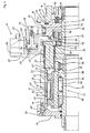
In der Zeichnung ist ein Ausführungsbeispiel einer gemäß der Erfindung ausgebildeten Spanneinrichtung dargestellt und nachfolgend im Einzelnen erläutert. Hierbei zeigt
- Figur 1
- die Spanneinrichtung in einem Axialschnitt während eines Arbeitsvorganges,
Figur 2- die Spanneinrichtung nach
Figur 1 in einem Halbschnitt und vergrößerter Darstellung, mit angekoppeltem Servomotor, Figur 3- die Spanneinrichtung nach
Figur 1 in einem Halbschnitt und vergrößerter Wiedergabe, - Figur 4
- einen Ausschnitt aus
Figur 3 Figur 5- eine Ausführungsvariante der Spanneinrichtung nach
Figur 1 , angebaut an der Maschinenspindel einer Werkzeugmaschine, in einer Darstellung nachFigur 3
- FIG. 1
- the clamping device in an axial section during a work process,
- FIG. 2
- the clamping device after
FIG. 1 in half section and enlarged view, with coupled servomotor, - FIG. 3
- the clamping device after
FIG. 1 in half section and enlarged playback, - FIG. 4
- a section from
FIG. 3 in enlarged reproduction and - FIG. 5
- a variant of the clamping device according to
FIG. 1 , attached to the machine spindle of a machine tool, in a representation afterFIG. 3 ,
Die in den
Der Servomotor 11 besteht aus einem achsparallel zur Längsachse A der Spanneinrichtung 1 ortsfest angeordneten Stator 12 und einem Rotor 13, mit dessen Rotorwelle 14 ein Ritzel 15 drehfest verbunden ist, das in eine an einem Antriebsrad 16 angebrachte Verzahnung 17 eingreift. Der Servomotor 11' kann aber auch, wie dies in
Der Bewegungswandler 31 ist bei der Ausgestaltung der Spanneinrichtung 1 nach
Bei der Ausgestaltung nach
Der Bewegungswandler 31 bzw. 31' besteht aus einer mit dem Servomotor 11 trieblich verbindbaren Hohlwelle 32 und Planetenrollen 33, die zwischen der Hohlwelle 32 und der Zugstange 7 eingesetzt sind und über ein Gewinde 34 in ein an der Zugstange 7 eingearbeitetes Außengewinde 35 eingreifen. Über ein Lager 36 und einem Ansatz 36', der in den Deckel 26 abgestützt ist, ist die Hohlwelle 32 verdrehfest gehalten.The
Die Triebverbindung zwischen dem dem Servomotor 11 zugeordneten Antriebsrat 16 und der Hohlwelle 32 des Bewegungswandlers 31 wird über die Schiebemuffe 51 bewerkstelligt. Bei dem in
Bei der Ausgestaltung nach
Der Kraftspeicher 41 bzw. 41' weist ein zwischen zwei mit konstantem Abstand zueinander angeordnete Wälzlager 43 und 44 eingesetztes Federpakte 42 sowie zwei winkelig gestaltete Hülsen 46 und 47 auf. Als Federpaket 42 sind eine Vielzahl von gleichmäßig über den Umfang verteilt angeordnete, zwischen den Hülsen 46 und 47 eingesetzte und auf Distanzbolzen 45 gehaltene Schraubendruckfedern 42' oder Tellerfedern 42" (
Zur Betätigung der Schiebemuffe 51 dient eine Servoeinrichtung 61, die aus einem in einen Zylinder 62 eingesetzten, von einem Druckmittel beidseitig beaufschlagbaren Kolben 63 besteht. Über ein Winkelstück 68, das in eine in die Schiebemuffe 51 eingearbeitete umlaufende Nut 56 eingreift, ist der Kolben 63 mit dieser trieblich verbunden.To actuate the sliding
Wird den Druckräumen 64 oder 65 der Servoeinrichtung 61 über ein Ventil 66 und Druckleitungen 67 oder 67' gesteuert Druckmittel zugeführt, so wird der Kolben 63 und mit diesem das Winkelstück 68 nach rechts oder links verschoben. Von dem Winkelstück 68 wird die Schiebemuffe 51 mitgenommen, so dass diese ebenfalls nach rechts oder links bewegt wird und die an deren Stirnflächen vorgesehenen Verzahnungen 52 oder 53 wechselweise in den an dem Antriebsrad 16 angebrachten Zahnkranz 18 oder den an dem Zwischenstück 23 oder der Hülse 22' angearbeiteten Zahnkranz 54 eingreifen. Die Zahnkränze 18, 52, 53 und 54 an dem Antriebsrad 16 der Schiebemuffe 51 und dem Gehäuse 21, sollten derart voneinander beabstandet sein, dass bei einer Verstellbewegung der Schiebemuffe 41 die ineinander greifenden Verzahnungen sich bis zur Endstellung der Schiebemuffe 41 überdecken. Damit die Triebverbindung zwischen der Schiebemuffe 51 und dem Gehäuse 21, bei eingerückten Verzahnungen der Zahnkränze 53 und 54, gesichert ist, ist die Schiebemuffe 51 mittels einer Druckfeder 55 an dem Flansch 28 abgestützt.If the
Um ein Werkstück 10 in dem Kraftspannfutter 5 einzuspannen, ist aus der in
Sobald eine wählbare Spannkraft erreicht ist, wird der Kraftspeicher 41 aktiviert. Die an dem Werkstück 10 anliegenden Spannbacken 6 bilden in diesem Betriebszustand, wie dies in
Nach dem Einspannen des Werkstückes 10 kann der Servomotor 11 von dem Bewegungswandler 31 getrennt werden. Dazu ist die Schiebemuffe 51 mit Hilfe der Servoeinrichtung 61 in die in
Und da das Gehäuse 21 mit der Maschinenspindel 3 der Werkzeugmaschine 2 fest verbunden ist, sind die an der Kraftübertragung beteiligten Bauteile der Spanneinrichtung 1 bzw. 1' - außer dem abgekoppelten Antriebsrad 16 - verblockt und laufen mit der Maschinenspindel 3 um. Ein selbsttätiges Öffnen des Kraftspannfutters 5 ist somit ausgeschlossen, so dass eine hohe Betriebssicherheit gewährleistet ist.And since the
Um auszuschließen, dass bei einem Schaltvorgang der Bewegungswandler 31 weder durch den Servomotor 11 noch durch die Maschinenspindel 3 gesichert ist, sind die zusammenwirkenden Verzahnungen des Antriebsrades 16, des Gehäuses 21 und der Schiebemuffe 51 derart angeordnet, dass sich bei einer Verstellbewegung der Schiebemuffe 51 die ineinander greifenden Verzahnungen bis zur Einnahme der jeweiligen Endstellung der Schiebemuffe 51 überdecken. Somit ist stets eine Abstützung des Bewegungswandlers 31 gegeben.To rule out that during a switching operation of the
Um auch mit Hilfe des Servomotors 11 während eines Bearbeitungsvorganges eine Erhöhung oder Reduzierung der Spannkraft des Kraftspannfutters 5 vornehmen zu können, ist, wie dies der
Um den Betriebszustand des Kraftspannfutters 5 während Arbeitsvorgängen überwachen zu können, ist die Spanneinrichtung 1', wie dies in
Claims (21)
- A clamping device (1), especially for machine tools (2), that is provided with a power-operated chuck (5) for holding a workpiece (10), for example, and the clamping jaws (6) of which can be actuated using the clamping device (1) by means of an axially moveable draw rod (7, 7'), in which the clamping device (1) possesses an electric servomotor (11) with a changeover function for triggering clamping movements, a movement converter (31) for converting the adjustment movements of the rotor shaft (14) of the servomotor (11) into the axial movements of the draw rod (7, 7') required for actuating the clamping jaws (6) and a force accumulator (41) for maintaining the clamping force, in which case the servomotor (11) for triggering clamping movements can be connected directly to the movement converter (31) via a controllably adjustable sliding sleeve (51) or by means of intermediate elements (38), the movement converter (31) and the force accumulator (41) are inserted in a housing (21) that can be connected to the machine spindle (3) of the machine tool (2) and, in the clamping position of the clamping device (1), the sliding sleeve (51) can be decoupled from the servomotor (11),
characterised in that,
in the clamping position of the clamping device (1), the housing (21) can be firmly connected to the movement converter (31) via this sliding sleeve (51). - The clamping device in accordance with Claim 1,
characterised in that
the housing (21) of the clamping device (1) is configured with a Z-shaped cross section and consists of a sleeve (22) facing towards the machine spindle (5) for holding the movement converter (31) and of the force accumulator (41) and of a hollow shaft (24) facing the servomotor (11) for holding the sliding sleeve (51), and that the sleeve (22) and the hollow shaft (24) of the housing (21) are connected together firmly by means of an intermediate wall (23). - The clamping device in accordance with Claim 2,
characterised in that
the housing (21) is configured as divided between the sleeve (22) or the hollow shaft (24) and the intermediate wall (23) or in the area of the same. - The clamping device in accordance with one of Claims 1 to 3,
characterised in that
one or more intermediate elements (38) are mounted in a rotating arrangement in the intermediate wall (23) of the housing (21) to provide the form-locking driving connection of the sliding sleeve (51) with the movement converter (31). - The clamping device in accordance Claim 4,
characterised in that
each of the intermediate elements (38) consists of a shaft (38') provided with differently designed gears (39, 40), which are connected on the one hand to the sliding sleeve (51) either directly or via an intermediate gear (57) and on the other hand with the movement converter (31), and are configured as a step-down gearbox. - The clamping device in accordance with Claim 1,
characterised in that
the cross section of the housing (21') is configured in the shape of a pot with an axially projecting sleeve (22') formed onto a plate-shaped ring (26') that can be connected to the machine spindle (3) with a radial gap from the draw rod (7'), with the movement converter (31') and the force accumulator (41') inserted into the sleeve (22'). - The clamping device in accordance with one of Claims 1 to 6,
characterised in that
the sliding sleeve (51) can be connected to a drive gear (16) connected to the servomotor (11) and to the housing (21') or its intermediate wall (23) by means of two sprocket wheels (52, 53) each arranged of the lateral end surfaces via sprocket wheels (18, 54) attached to the intermediate wall (23), in an alternating form-locking arrangement. - The clamping device in accordance with Claim 7,
characterised in that
the teeth on the sprocket wheels (18, 54, 52, 53) fitted in the drive gear (16), the housing (21') and the sliding sleeve (51) are arranged and spaced apart from one another, that when there is an adjustment movement of the sliding sleeve (51), the intermeshing teeth overlap until the corresponding limit position of the sliding sleeve (51) is adopted. - The clamping device in accordance with one of Claims 1 to 8,
characterised in that
the sliding sleeve (51) is supported against the force of one or more compression springs (55) on a flange (28) attached to the hollow shaft (24) of the housing (21). - The clamping device in accordance with one of Claims 1 to 9,
characterised in that
the sliding sleeve (51) is moved axially by means of a servo device (61), for example in the form of an adjusting piston (63) inserted in a cylinder (62) and adjustable by means of a pressurised medium, or by an electromagnet. - The clamping device in accordance with one of Claims 1 to 10,
characterised in that
the servomotor (11, 11') that can be connected to the drive gear (16) directly or via intermediate elements is arranged flush, axially in parallel or axially at right angles to the lengthways axis (A) of the housing (21) of the clamping device (1). - The clamping device in accordance with one of Claims 1 to 11,
characterised in that
the movement converter (31) is formed by a planetary roller (33) arranged between a hollow shaft (32) that can be connected to the servomotor (11) and the draw rod (7'). - The clamping device in accordance with Claim 12,
characterised in that
the force accumulator (41) is arranged on the hollow shaft (32) of the movement converter (31) and can be activated by the hollow shaft (32). - The clamping device in accordance Claim 13,
characterised in that
the force accumulator (41) consists of a spring pack (42) inserted between two roller bearings (43, 44) with a constant spacing and clamped against one another, and two sleeves (46, 47) provided at the side next to the spring pack (42) which extend over the roller bearings (43, 44), with the spring pack (42) making contact with the end faces (46', 47') of the sleeves (46, 47) that face towards one another, and that in order to activate the force accumulator (41), stops (48, 49) provided on the housing (21) are allocated to the sleeves (46, 47), with the outer end surfaces (46", 47") of the sleeves (46, 47) interacting alternately with the stops (48, 49). - The clamping device in accordance with Claim 14,
characterised in that
the spring pack (42) consists of several coil pressure springs (42') inserted between the two roller bearings (43, 44) or spacer pins (45) supported can the outer races and lined up in an even distribution around the circumference, or coil pressure springs (42') arranged next to the spacer pins (45), in which case the coil pressure springs (42') should preferably have a rectangular cross section or be formed from cup springs (42"). - The clamping device in accordance with Claim 14 or 15,
characterised in that
by clamping the force accumulator (41) with the supported draw rod (7, 7'), the hollow shaft (32) of the movement converter (31) can be adjusted in each case opposite to the adjustment direction of the draw rod (7, 7'), through an adjustment distance (x) that, in a preferred embodiment, can be selected in both adjustment directions. - The clamping device in accordance with one of Claims 1 to 16,
characterised in that
the clamping device (1) is provided with a distance measuring device (71). - The clamping device in accordance with Claim 17,
characterised in that
the distance measuring device (71) consists of a position indicator (72) arranged directly on the draw rod (7') or attached to it by means of intermediate elements, for example in the form of a sensor ring (73), and of a sensor (74) arranged in a fixed location, the signals from which can be sent to a display unit. - The clamping device in accordance with Claim 18,
characterised in that
the position indicator (72) of the distance measuring device (71) passes through the housing (21) of the clamping device (1) and the sensor (74) is supported on the machine tool (2) at the height of the position indicator (72). - The clamping device in accordance with one of Claims 1 to 19,
characterised in that
the drive motor (4) of the machine tool (2) is electrically connected to the servomotor (11) by means of a control unit (70). - A process for controlling the servomotor of a clamping device in accordance with one of Claims 1 to 18 depending on the rotation speed of the drive motor of the machine tool,
characterised in that
the rotation speed of the servomotor (11) can be adjusted by means of the control unit (70) for increasing or reducing the clamping force of the power-operated chuck (5) during a machining process, so that the servomotor (11) rotates synchronously with the rotation speed of the drive motor (4) for coupling the drive gear (16) with the sliding sleeve (51), and that the servomotor (11) is driven with increased or reduced speed in relation to the synchronous speed in order to increase or reduce the clamping force.
Priority Applications (3)
| Application Number | Priority Date | Filing Date | Title |
|---|---|---|---|
| EP10161837A EP2384839B1 (en) | 2010-05-04 | 2010-05-04 | Clamping device |
| JP2011099289A JP5449251B2 (en) | 2010-05-04 | 2011-04-27 | Clamping device |
| US13/068,177 US20110272898A1 (en) | 2010-05-04 | 2011-05-04 | Clamping device |
Applications Claiming Priority (1)
| Application Number | Priority Date | Filing Date | Title |
|---|---|---|---|
| EP10161837A EP2384839B1 (en) | 2010-05-04 | 2010-05-04 | Clamping device |
Publications (2)
| Publication Number | Publication Date |
|---|---|
| EP2384839A1 EP2384839A1 (en) | 2011-11-09 |
| EP2384839B1 true EP2384839B1 (en) | 2013-01-02 |
Family
ID=42664665
Family Applications (1)
| Application Number | Title | Priority Date | Filing Date |
|---|---|---|---|
| EP10161837A Active EP2384839B1 (en) | 2010-05-04 | 2010-05-04 | Clamping device |
Country Status (3)
| Country | Link |
|---|---|
| US (1) | US20110272898A1 (en) |
| EP (1) | EP2384839B1 (en) |
| JP (1) | JP5449251B2 (en) |
Cited By (3)
| Publication number | Priority date | Publication date | Assignee | Title |
|---|---|---|---|---|
| EP2796233A1 (en) | 2013-04-24 | 2014-10-29 | Karl Hiestand | Coupling device |
| EP2837450A1 (en) | 2013-08-16 | 2015-02-18 | SMW-AUTOBLOK Spannsysteme GmbH | Clamping device |
| EP2837451A1 (en) | 2013-08-16 | 2015-02-18 | SMW-AUTOBLOK Spannsysteme GmbH | Method for performing a coupling process |
Families Citing this family (15)
| Publication number | Priority date | Publication date | Assignee | Title |
|---|---|---|---|---|
| DE102011113765A1 (en) | 2011-09-19 | 2013-03-21 | Ludwig Ehrhardt Gmbh | Clamping device with an electric motor |
| JP5885565B2 (en) * | 2012-01-17 | 2016-03-15 | 株式会社プラスエンジニアリング | Electric power transmission device for machine tools |
| DE102012100821A1 (en) * | 2012-02-01 | 2013-08-01 | Röhm Gmbh | chuck |
| EP2700461B1 (en) * | 2012-08-20 | 2016-05-18 | Klingelnberg AG | Device for clamping a tool or workpiece and method for actuating such a clamping device |
| EP2724801B1 (en) | 2012-10-26 | 2020-12-09 | Karl Hiestand | Tensioning assembly |
| EP2868410B1 (en) * | 2013-10-30 | 2017-12-13 | MTH GbR Markus und Thomas Hiestand | Clamping device for machine tools |
| KR101574962B1 (en) * | 2014-05-02 | 2015-12-21 | 쑤안-룽 우 | Chuck device having two collets |
| EP3040144B1 (en) * | 2015-01-05 | 2019-12-04 | MTH GbR Markus und Thomas Hiestand | Clamping device |
| EP3175942B1 (en) | 2015-12-01 | 2018-04-11 | MTH GbR Markus und Thomas Hiestand | Clamping device |
| CN108946121B (en) * | 2018-06-25 | 2023-11-21 | 济南邦德激光股份有限公司 | Tubular product rotation feeding device |
| CN109574492B (en) * | 2019-01-21 | 2023-08-08 | 苏州赛森电子科技有限公司 | Clamping device and method for PCVD wire drawing |
| CN109896485B (en) * | 2019-04-25 | 2024-01-02 | 郑州奥特智能设备股份有限公司 | Screwing device for bottle cap screwing robot |
| CN114029755A (en) * | 2021-12-06 | 2022-02-11 | 深圳市怡华兴电子有限公司 | Lathe machining equipment capable of reducing swing amplitude |
| CN115144618B (en) * | 2022-09-01 | 2022-12-20 | 国网山东省电力公司枣庄供电公司 | Motor electrical variable measuring device and measuring method |
| CN116572034B (en) * | 2023-05-12 | 2023-11-03 | 苏州金亿精密齿轮有限公司 | Clamping and fixing device for machining speed reducer gear and using method thereof |
Family Cites Families (12)
| Publication number | Priority date | Publication date | Assignee | Title |
|---|---|---|---|---|
| US4567794A (en) * | 1982-05-13 | 1986-02-04 | Hubert Bald | Apparatus for producing an axial clamping force for rotating spindles, and a method of operation for an apparatus of this kind |
| DE3218083C2 (en) * | 1982-05-13 | 1986-11-27 | Hubert Dipl.-Ing. 5920 Bad Berleburg Bald | Device for generating a setting torque, in particular for adjusting the position of the jaws of a chuck or the clamping force exerted by them |
| DE3684894D1 (en) | 1985-12-28 | 1992-05-21 | Forkardt Paul Gmbh | MACHINE TOOL AND ITS OPERATING METHOD. |
| DE3727445C1 (en) * | 1986-09-06 | 1988-03-10 | Hubert Dipl-Ing Bald | Arrangement for adjusting the jaws in power-operated chucks |
| JPS6379107U (en) * | 1986-11-14 | 1988-05-25 | ||
| JPS63191508A (en) * | 1987-02-04 | 1988-08-09 | Shinko Electric Co Ltd | Electric chuck device |
| JPS63221910A (en) * | 1987-03-10 | 1988-09-14 | Shinko Electric Co Ltd | Motor-driven chuck device |
| JPH11320222A (en) * | 1998-05-07 | 1999-11-24 | Okuma Corp | Chuck device |
| JP2001225215A (en) * | 2000-02-10 | 2001-08-21 | Mitsubishi Electric Corp | Collet chuck opening/closing device and machining device having the same collet chuck opening/closing device |
| JP4549032B2 (en) * | 2003-03-14 | 2010-09-22 | 株式会社野村製作所 | Chuck drive device and drive method |
| JP2004291191A (en) * | 2003-03-28 | 2004-10-21 | Kitagawa Iron Works Co Ltd | Electric operating apparatus for chuck |
| EP2103368A1 (en) * | 2008-03-20 | 2009-09-23 | Karl Hiestand | Clamping device for machine tools |
-
2010
- 2010-05-04 EP EP10161837A patent/EP2384839B1/en active Active
-
2011
- 2011-04-27 JP JP2011099289A patent/JP5449251B2/en not_active Expired - Fee Related
- 2011-05-04 US US13/068,177 patent/US20110272898A1/en not_active Abandoned
Cited By (3)
| Publication number | Priority date | Publication date | Assignee | Title |
|---|---|---|---|---|
| EP2796233A1 (en) | 2013-04-24 | 2014-10-29 | Karl Hiestand | Coupling device |
| EP2837450A1 (en) | 2013-08-16 | 2015-02-18 | SMW-AUTOBLOK Spannsysteme GmbH | Clamping device |
| EP2837451A1 (en) | 2013-08-16 | 2015-02-18 | SMW-AUTOBLOK Spannsysteme GmbH | Method for performing a coupling process |
Also Published As
| Publication number | Publication date |
|---|---|
| US20110272898A1 (en) | 2011-11-10 |
| JP2011235436A (en) | 2011-11-24 |
| EP2384839A1 (en) | 2011-11-09 |
| JP5449251B2 (en) | 2014-03-19 |
Similar Documents
| Publication | Publication Date | Title |
|---|---|---|
| EP2384839B1 (en) | Clamping device | |
| EP2548681B1 (en) | Clamping device for machine tools | |
| EP1637260B1 (en) | Clamping device for machine tool | |
| EP2295176B1 (en) | Tensioning assembly | |
| EP3040144B1 (en) | Clamping device | |
| EP2868410B1 (en) | Clamping device for machine tools | |
| DE3938353C2 (en) | Spindle drive device for generating optional linear and / or rotary movements of the spindle | |
| DE102007053044B3 (en) | Threaded core unscrewing device for unscrewing threaded core from injection molding tool, has driving motor arranged laterally beside threaded core screw nut, where motor is hydraulic motor or electrical step or linear motor | |
| DE3218084A1 (en) | DEVICE FOR GENERATING A POSITION ROTATIONAL MOVEMENT | |
| EP3362215B1 (en) | Clamping device | |
| EP2103368A1 (en) | Clamping device for machine tools | |
| EP2796233A1 (en) | Coupling device | |
| EP1992436A1 (en) | Motor-driven working spindle for a machine tool | |
| EP3911475B1 (en) | Clamping device | |
| EP2508298A1 (en) | Holding and drive device for a tube support element | |
| EP2724801B1 (en) | Tensioning assembly | |
| EP0618025A1 (en) | Injection unit | |
| EP2363223B1 (en) | Clamping device for machine tools | |
| EP2837450B1 (en) | Clamping device | |
| WO2001038070A1 (en) | Device and method for carrying out a two-stage linear movement | |
| EP2283955A1 (en) | Clamping device for machine tools | |
| EP1163976A1 (en) | Drive with a variable transmission for a toolholder device | |
| EP3127640B1 (en) | Clamping device | |
| EP1226372B1 (en) | Furniture drive | |
| DE102019105643A1 (en) | Clamping device |
Legal Events
| Date | Code | Title | Description |
|---|---|---|---|
| AK | Designated contracting states |
Kind code of ref document: A1 Designated state(s): AL AT BE BG CH CY CZ DE DK EE ES FI FR GB GR HR HU IE IS IT LI LT LU LV MC MK MT NL NO PL PT RO SE SI SK SM TR |
|
| AX | Request for extension of the european patent |
Extension state: BA ME RS |
|
| PUAI | Public reference made under article 153(3) epc to a published international application that has entered the european phase |
Free format text: ORIGINAL CODE: 0009012 |
|
| 17P | Request for examination filed |
Effective date: 20120120 |
|
| GRAP | Despatch of communication of intention to grant a patent |
Free format text: ORIGINAL CODE: EPIDOSNIGR1 |
|
| GRAS | Grant fee paid |
Free format text: ORIGINAL CODE: EPIDOSNIGR3 |
|
| GRAA | (expected) grant |
Free format text: ORIGINAL CODE: 0009210 |
|
| AK | Designated contracting states |
Kind code of ref document: B1 Designated state(s): AL AT BE BG CH CY CZ DE DK EE ES FI FR GB GR HR HU IE IS IT LI LT LU LV MC MK MT NL NO PL PT RO SE SI SK SM TR |
|
| REG | Reference to a national code |
Ref country code: GB Ref legal event code: FG4D Free format text: NOT ENGLISH |
|
| REG | Reference to a national code |
Ref country code: AT Ref legal event code: REF Ref document number: 591311 Country of ref document: AT Kind code of ref document: T Effective date: 20130115 Ref country code: CH Ref legal event code: EP |
|
| REG | Reference to a national code |
Ref country code: IE Ref legal event code: FG4D Free format text: LANGUAGE OF EP DOCUMENT: GERMAN |
|
| REG | Reference to a national code |
Ref country code: DE Ref legal event code: R096 Ref document number: 502010002002 Country of ref document: DE Effective date: 20130307 |
|
| REG | Reference to a national code |
Ref country code: NL Ref legal event code: VDEP Effective date: 20130102 |
|
| PG25 | Lapsed in a contracting state [announced via postgrant information from national office to epo] |
Ref country code: SI Free format text: LAPSE BECAUSE OF FAILURE TO SUBMIT A TRANSLATION OF THE DESCRIPTION OR TO PAY THE FEE WITHIN THE PRESCRIBED TIME-LIMIT Effective date: 20130102 |
|
| REG | Reference to a national code |
Ref country code: LT Ref legal event code: MG4D |
|
| PG25 | Lapsed in a contracting state [announced via postgrant information from national office to epo] |
Ref country code: NO Free format text: LAPSE BECAUSE OF FAILURE TO SUBMIT A TRANSLATION OF THE DESCRIPTION OR TO PAY THE FEE WITHIN THE PRESCRIBED TIME-LIMIT Effective date: 20130402 Ref country code: ES Free format text: LAPSE BECAUSE OF FAILURE TO SUBMIT A TRANSLATION OF THE DESCRIPTION OR TO PAY THE FEE WITHIN THE PRESCRIBED TIME-LIMIT Effective date: 20130413 Ref country code: LT Free format text: LAPSE BECAUSE OF FAILURE TO SUBMIT A TRANSLATION OF THE DESCRIPTION OR TO PAY THE FEE WITHIN THE PRESCRIBED TIME-LIMIT Effective date: 20130102 Ref country code: SE Free format text: LAPSE BECAUSE OF FAILURE TO SUBMIT A TRANSLATION OF THE DESCRIPTION OR TO PAY THE FEE WITHIN THE PRESCRIBED TIME-LIMIT Effective date: 20130102 Ref country code: CZ Free format text: LAPSE BECAUSE OF FAILURE TO SUBMIT A TRANSLATION OF THE DESCRIPTION OR TO PAY THE FEE WITHIN THE PRESCRIBED TIME-LIMIT Effective date: 20130102 Ref country code: IS Free format text: LAPSE BECAUSE OF FAILURE TO SUBMIT A TRANSLATION OF THE DESCRIPTION OR TO PAY THE FEE WITHIN THE PRESCRIBED TIME-LIMIT Effective date: 20130502 Ref country code: BG Free format text: LAPSE BECAUSE OF FAILURE TO SUBMIT A TRANSLATION OF THE DESCRIPTION OR TO PAY THE FEE WITHIN THE PRESCRIBED TIME-LIMIT Effective date: 20130402 |
|
| PG25 | Lapsed in a contracting state [announced via postgrant information from national office to epo] |
Ref country code: FI Free format text: LAPSE BECAUSE OF FAILURE TO SUBMIT A TRANSLATION OF THE DESCRIPTION OR TO PAY THE FEE WITHIN THE PRESCRIBED TIME-LIMIT Effective date: 20130102 Ref country code: NL Free format text: LAPSE BECAUSE OF FAILURE TO SUBMIT A TRANSLATION OF THE DESCRIPTION OR TO PAY THE FEE WITHIN THE PRESCRIBED TIME-LIMIT Effective date: 20130102 Ref country code: GR Free format text: LAPSE BECAUSE OF FAILURE TO SUBMIT A TRANSLATION OF THE DESCRIPTION OR TO PAY THE FEE WITHIN THE PRESCRIBED TIME-LIMIT Effective date: 20130403 Ref country code: PT Free format text: LAPSE BECAUSE OF FAILURE TO SUBMIT A TRANSLATION OF THE DESCRIPTION OR TO PAY THE FEE WITHIN THE PRESCRIBED TIME-LIMIT Effective date: 20130502 Ref country code: LV Free format text: LAPSE BECAUSE OF FAILURE TO SUBMIT A TRANSLATION OF THE DESCRIPTION OR TO PAY THE FEE WITHIN THE PRESCRIBED TIME-LIMIT Effective date: 20130102 Ref country code: PL Free format text: LAPSE BECAUSE OF FAILURE TO SUBMIT A TRANSLATION OF THE DESCRIPTION OR TO PAY THE FEE WITHIN THE PRESCRIBED TIME-LIMIT Effective date: 20130102 |
|
| PG25 | Lapsed in a contracting state [announced via postgrant information from national office to epo] |
Ref country code: HR Free format text: LAPSE BECAUSE OF FAILURE TO SUBMIT A TRANSLATION OF THE DESCRIPTION OR TO PAY THE FEE WITHIN THE PRESCRIBED TIME-LIMIT Effective date: 20130102 |
|
| PG25 | Lapsed in a contracting state [announced via postgrant information from national office to epo] |
Ref country code: RO Free format text: LAPSE BECAUSE OF FAILURE TO SUBMIT A TRANSLATION OF THE DESCRIPTION OR TO PAY THE FEE WITHIN THE PRESCRIBED TIME-LIMIT Effective date: 20130102 Ref country code: DK Free format text: LAPSE BECAUSE OF FAILURE TO SUBMIT A TRANSLATION OF THE DESCRIPTION OR TO PAY THE FEE WITHIN THE PRESCRIBED TIME-LIMIT Effective date: 20130102 Ref country code: SK Free format text: LAPSE BECAUSE OF FAILURE TO SUBMIT A TRANSLATION OF THE DESCRIPTION OR TO PAY THE FEE WITHIN THE PRESCRIBED TIME-LIMIT Effective date: 20130102 Ref country code: EE Free format text: LAPSE BECAUSE OF FAILURE TO SUBMIT A TRANSLATION OF THE DESCRIPTION OR TO PAY THE FEE WITHIN THE PRESCRIBED TIME-LIMIT Effective date: 20130102 |
|
| PLBE | No opposition filed within time limit |
Free format text: ORIGINAL CODE: 0009261 |
|
| STAA | Information on the status of an ep patent application or granted ep patent |
Free format text: STATUS: NO OPPOSITION FILED WITHIN TIME LIMIT |
|
| PG25 | Lapsed in a contracting state [announced via postgrant information from national office to epo] |
Ref country code: CY Free format text: LAPSE BECAUSE OF FAILURE TO SUBMIT A TRANSLATION OF THE DESCRIPTION OR TO PAY THE FEE WITHIN THE PRESCRIBED TIME-LIMIT Effective date: 20130102 |
|
| BERE | Be: lapsed |
Owner name: HIESTAND, KARL Effective date: 20130531 |
|
| 26N | No opposition filed |
Effective date: 20131003 |
|
| PG25 | Lapsed in a contracting state [announced via postgrant information from national office to epo] |
Ref country code: MC Free format text: LAPSE BECAUSE OF FAILURE TO SUBMIT A TRANSLATION OF THE DESCRIPTION OR TO PAY THE FEE WITHIN THE PRESCRIBED TIME-LIMIT Effective date: 20130102 |
|
| REG | Reference to a national code |
Ref country code: DE Ref legal event code: R097 Ref document number: 502010002002 Country of ref document: DE Effective date: 20131003 |
|
| REG | Reference to a national code |
Ref country code: IE Ref legal event code: MM4A |
|
| PG25 | Lapsed in a contracting state [announced via postgrant information from national office to epo] |
Ref country code: BE Free format text: LAPSE BECAUSE OF NON-PAYMENT OF DUE FEES Effective date: 20130531 |
|
| PG25 | Lapsed in a contracting state [announced via postgrant information from national office to epo] |
Ref country code: IE Free format text: LAPSE BECAUSE OF NON-PAYMENT OF DUE FEES Effective date: 20130504 |
|
| PG25 | Lapsed in a contracting state [announced via postgrant information from national office to epo] |
Ref country code: MT Free format text: LAPSE BECAUSE OF FAILURE TO SUBMIT A TRANSLATION OF THE DESCRIPTION OR TO PAY THE FEE WITHIN THE PRESCRIBED TIME-LIMIT Effective date: 20130102 |
|
| PG25 | Lapsed in a contracting state [announced via postgrant information from national office to epo] |
Ref country code: SM Free format text: LAPSE BECAUSE OF FAILURE TO SUBMIT A TRANSLATION OF THE DESCRIPTION OR TO PAY THE FEE WITHIN THE PRESCRIBED TIME-LIMIT Effective date: 20130102 |
|
| PG25 | Lapsed in a contracting state [announced via postgrant information from national office to epo] |
Ref country code: TR Free format text: LAPSE BECAUSE OF FAILURE TO SUBMIT A TRANSLATION OF THE DESCRIPTION OR TO PAY THE FEE WITHIN THE PRESCRIBED TIME-LIMIT Effective date: 20130102 |
|
| PG25 | Lapsed in a contracting state [announced via postgrant information from national office to epo] |
Ref country code: HU Free format text: LAPSE BECAUSE OF FAILURE TO SUBMIT A TRANSLATION OF THE DESCRIPTION OR TO PAY THE FEE WITHIN THE PRESCRIBED TIME-LIMIT; INVALID AB INITIO Effective date: 20100504 Ref country code: LU Free format text: LAPSE BECAUSE OF NON-PAYMENT OF DUE FEES Effective date: 20130504 Ref country code: MK Free format text: LAPSE BECAUSE OF FAILURE TO SUBMIT A TRANSLATION OF THE DESCRIPTION OR TO PAY THE FEE WITHIN THE PRESCRIBED TIME-LIMIT Effective date: 20130102 |
|
| REG | Reference to a national code |
Ref country code: FR Ref legal event code: PLFP Year of fee payment: 7 |
|
| REG | Reference to a national code |
Ref country code: DE Ref legal event code: R082 Ref document number: 502010002002 Country of ref document: DE Representative=s name: RIEBLING, PETER, DIPL.-ING. DR.-ING., DE Ref country code: DE Ref legal event code: R082 Ref document number: 502010002002 Country of ref document: DE |
|
| REG | Reference to a national code |
Ref country code: DE Ref legal event code: R082 Ref document number: 502010002002 Country of ref document: DE Representative=s name: RIEBLING, PETER, DIPL.-ING. DR.-ING., DE |
|
| REG | Reference to a national code |
Ref country code: FR Ref legal event code: PLFP Year of fee payment: 8 |
|
| PGFP | Annual fee paid to national office [announced via postgrant information from national office to epo] |
Ref country code: GB Payment date: 20170524 Year of fee payment: 8 Ref country code: CH Payment date: 20170523 Year of fee payment: 8 Ref country code: FR Payment date: 20170522 Year of fee payment: 8 |
|
| PGFP | Annual fee paid to national office [announced via postgrant information from national office to epo] |
Ref country code: AT Payment date: 20170519 Year of fee payment: 8 |
|
| PG25 | Lapsed in a contracting state [announced via postgrant information from national office to epo] |
Ref country code: AL Free format text: LAPSE BECAUSE OF FAILURE TO SUBMIT A TRANSLATION OF THE DESCRIPTION OR TO PAY THE FEE WITHIN THE PRESCRIBED TIME-LIMIT Effective date: 20130102 |
|
| REG | Reference to a national code |
Ref country code: CH Ref legal event code: PL |
|
| REG | Reference to a national code |
Ref country code: AT Ref legal event code: MM01 Ref document number: 591311 Country of ref document: AT Kind code of ref document: T Effective date: 20180504 |
|
| GBPC | Gb: european patent ceased through non-payment of renewal fee |
Effective date: 20180504 |
|
| PG25 | Lapsed in a contracting state [announced via postgrant information from national office to epo] |
Ref country code: AT Free format text: LAPSE BECAUSE OF NON-PAYMENT OF DUE FEES Effective date: 20180504 |
|
| PG25 | Lapsed in a contracting state [announced via postgrant information from national office to epo] |
Ref country code: LI Free format text: LAPSE BECAUSE OF NON-PAYMENT OF DUE FEES Effective date: 20180531 Ref country code: CH Free format text: LAPSE BECAUSE OF NON-PAYMENT OF DUE FEES Effective date: 20180531 |
|
| PG25 | Lapsed in a contracting state [announced via postgrant information from national office to epo] |
Ref country code: GB Free format text: LAPSE BECAUSE OF NON-PAYMENT OF DUE FEES Effective date: 20180504 Ref country code: FR Free format text: LAPSE BECAUSE OF NON-PAYMENT OF DUE FEES Effective date: 20180531 |
|
| PGFP | Annual fee paid to national office [announced via postgrant information from national office to epo] |
Ref country code: IT Payment date: 20230531 Year of fee payment: 14 Ref country code: DE Payment date: 20230519 Year of fee payment: 14 |