EP2381008A2 - Katalysatorgestütztes chemisches Verarbeitungsverfahren und entsprechende Vorrichtung - Google Patents
Katalysatorgestütztes chemisches Verarbeitungsverfahren und entsprechende Vorrichtung Download PDFInfo
- Publication number
- EP2381008A2 EP2381008A2 EP20110006032 EP11006032A EP2381008A2 EP 2381008 A2 EP2381008 A2 EP 2381008A2 EP 20110006032 EP20110006032 EP 20110006032 EP 11006032 A EP11006032 A EP 11006032A EP 2381008 A2 EP2381008 A2 EP 2381008A2
- Authority
- EP
- European Patent Office
- Prior art keywords
- workpiece
- processing
- catalyst
- processed
- solid catalyst
- Prior art date
- Legal status (The legal status is an assumption and is not a legal conclusion. Google has not performed a legal analysis and makes no representation as to the accuracy of the status listed.)
- Withdrawn
Links
- 238000000034 method Methods 0.000 title claims abstract description 169
- 238000012993 chemical processing Methods 0.000 title claims abstract description 142
- 238000012545 processing Methods 0.000 claims abstract description 704
- 239000007788 liquid Substances 0.000 claims abstract description 280
- 239000000463 material Substances 0.000 claims abstract description 45
- 239000011949 solid catalyst Substances 0.000 claims description 267
- 230000002378 acidificating effect Effects 0.000 claims description 122
- 230000001590 oxidative effect Effects 0.000 claims description 71
- MHAJPDPJQMAIIY-UHFFFAOYSA-N Hydrogen peroxide Chemical compound OO MHAJPDPJQMAIIY-UHFFFAOYSA-N 0.000 claims description 38
- 230000001678 irradiating effect Effects 0.000 claims description 35
- 229910052802 copper Inorganic materials 0.000 claims description 33
- XLYOFNOQVPJJNP-UHFFFAOYSA-N water Substances O XLYOFNOQVPJJNP-UHFFFAOYSA-N 0.000 claims description 30
- CBENFWSGALASAD-UHFFFAOYSA-N Ozone Chemical compound [O-][O+]=O CBENFWSGALASAD-UHFFFAOYSA-N 0.000 claims description 29
- -1 hydrogen ions Chemical class 0.000 claims description 29
- 230000007246 mechanism Effects 0.000 claims description 27
- QVGXLLKOCUKJST-UHFFFAOYSA-N atomic oxygen Chemical compound [O] QVGXLLKOCUKJST-UHFFFAOYSA-N 0.000 claims description 20
- 239000001301 oxygen Substances 0.000 claims description 20
- 229910052760 oxygen Inorganic materials 0.000 claims description 20
- 239000001257 hydrogen Substances 0.000 claims description 19
- 229910052739 hydrogen Inorganic materials 0.000 claims description 19
- 238000005342 ion exchange Methods 0.000 claims description 13
- 229910021642 ultra pure water Inorganic materials 0.000 claims description 13
- 239000012498 ultrapure water Substances 0.000 claims description 13
- 229910052782 aluminium Inorganic materials 0.000 claims description 10
- 229910052742 iron Inorganic materials 0.000 claims description 10
- 229910052719 titanium Inorganic materials 0.000 claims description 10
- 239000006172 buffering agent Substances 0.000 claims description 9
- 229910044991 metal oxide Inorganic materials 0.000 claims description 9
- 150000004706 metal oxides Chemical group 0.000 claims description 9
- 229910052759 nickel Inorganic materials 0.000 claims description 9
- 239000004745 nonwoven fabric Substances 0.000 claims description 9
- 239000000843 powder Substances 0.000 claims description 9
- 229910052733 gallium Inorganic materials 0.000 claims description 8
- 229910052721 tungsten Inorganic materials 0.000 claims description 7
- 229910052751 metal Inorganic materials 0.000 claims description 6
- 239000002184 metal Substances 0.000 claims description 5
- 239000011347 resin Substances 0.000 claims description 5
- 229920005989 resin Polymers 0.000 claims description 5
- 229910002601 GaN Inorganic materials 0.000 claims 1
- 239000003054 catalyst Substances 0.000 abstract description 203
- 230000008569 process Effects 0.000 abstract description 55
- ZOKXTWBITQBERF-UHFFFAOYSA-N Molybdenum Chemical compound [Mo] ZOKXTWBITQBERF-UHFFFAOYSA-N 0.000 abstract description 43
- 239000011733 molybdenum Substances 0.000 abstract description 43
- 229910052750 molybdenum Inorganic materials 0.000 abstract description 43
- 229910052736 halogen Inorganic materials 0.000 abstract description 34
- 150000002367 halogens Chemical class 0.000 abstract description 16
- 239000005078 molybdenum compound Substances 0.000 abstract description 13
- 150000002752 molybdenum compounds Chemical class 0.000 abstract description 13
- 238000006243 chemical reaction Methods 0.000 description 125
- KRHYYFGTRYWZRS-UHFFFAOYSA-N Fluorane Chemical compound F KRHYYFGTRYWZRS-UHFFFAOYSA-N 0.000 description 82
- BASFCYQUMIYNBI-UHFFFAOYSA-N platinum Chemical compound [Pt] BASFCYQUMIYNBI-UHFFFAOYSA-N 0.000 description 48
- 239000007800 oxidant agent Substances 0.000 description 44
- 238000005498 polishing Methods 0.000 description 35
- 238000003672 processing method Methods 0.000 description 35
- 239000010949 copper Substances 0.000 description 33
- 125000004429 atom Chemical group 0.000 description 30
- RYGMFSIKBFXOCR-UHFFFAOYSA-N Copper Chemical compound [Cu] RYGMFSIKBFXOCR-UHFFFAOYSA-N 0.000 description 29
- 238000010586 diagram Methods 0.000 description 29
- 230000005284 excitation Effects 0.000 description 23
- 229910000040 hydrogen fluoride Inorganic materials 0.000 description 23
- 229910052697 platinum Inorganic materials 0.000 description 23
- 239000000243 solution Substances 0.000 description 23
- 239000000126 substance Substances 0.000 description 23
- 125000004430 oxygen atom Chemical group O* 0.000 description 19
- QPLDLSVMHZLSFG-UHFFFAOYSA-N Copper oxide Chemical compound [Cu]=O QPLDLSVMHZLSFG-UHFFFAOYSA-N 0.000 description 18
- XEEYBQQBJWHFJM-UHFFFAOYSA-N iron Substances [Fe] XEEYBQQBJWHFJM-UHFFFAOYSA-N 0.000 description 17
- 229910052737 gold Inorganic materials 0.000 description 16
- 239000010931 gold Substances 0.000 description 16
- PCHJSUWPFVWCPO-UHFFFAOYSA-N gold Chemical compound [Au] PCHJSUWPFVWCPO-UHFFFAOYSA-N 0.000 description 15
- MCMNRKCIXSYSNV-UHFFFAOYSA-N Zirconium dioxide Chemical compound O=[Zr]=O MCMNRKCIXSYSNV-UHFFFAOYSA-N 0.000 description 14
- 230000008859 change Effects 0.000 description 14
- 229910003460 diamond Inorganic materials 0.000 description 14
- 239000010432 diamond Substances 0.000 description 14
- 238000000354 decomposition reaction Methods 0.000 description 13
- 150000002500 ions Chemical class 0.000 description 13
- 150000001875 compounds Chemical class 0.000 description 12
- 238000005530 etching Methods 0.000 description 12
- PXHVJJICTQNCMI-UHFFFAOYSA-N nickel Substances [Ni] PXHVJJICTQNCMI-UHFFFAOYSA-N 0.000 description 12
- 239000002253 acid Substances 0.000 description 11
- 239000000919 ceramic Substances 0.000 description 11
- 230000003647 oxidation Effects 0.000 description 11
- 238000007254 oxidation reaction Methods 0.000 description 11
- 239000002585 base Substances 0.000 description 10
- 239000007853 buffer solution Substances 0.000 description 10
- 238000010494 dissociation reaction Methods 0.000 description 10
- 241000894007 species Species 0.000 description 10
- 239000005751 Copper oxide Substances 0.000 description 9
- 229910000431 copper oxide Inorganic materials 0.000 description 9
- VYPSYNLAJGMNEJ-UHFFFAOYSA-N silicon dioxide Inorganic materials O=[Si]=O VYPSYNLAJGMNEJ-UHFFFAOYSA-N 0.000 description 9
- 239000010936 titanium Substances 0.000 description 9
- JPVYNHNXODAKFH-UHFFFAOYSA-N Cu2+ Chemical compound [Cu+2] JPVYNHNXODAKFH-UHFFFAOYSA-N 0.000 description 8
- 239000006061 abrasive grain Substances 0.000 description 8
- XAGFODPZIPBFFR-UHFFFAOYSA-N aluminium Chemical compound [Al] XAGFODPZIPBFFR-UHFFFAOYSA-N 0.000 description 8
- 238000003825 pressing Methods 0.000 description 8
- 229910052594 sapphire Inorganic materials 0.000 description 8
- 239000010980 sapphire Substances 0.000 description 8
- GYHNNYVSQQEPJS-UHFFFAOYSA-N Gallium Chemical compound [Ga] GYHNNYVSQQEPJS-UHFFFAOYSA-N 0.000 description 7
- 229910001182 Mo alloy Inorganic materials 0.000 description 7
- 230000003197 catalytic effect Effects 0.000 description 7
- 238000004090 dissolution Methods 0.000 description 7
- 239000010979 ruby Substances 0.000 description 7
- 229910001750 ruby Inorganic materials 0.000 description 7
- 239000003381 stabilizer Substances 0.000 description 7
- 229910052723 transition metal Inorganic materials 0.000 description 7
- 150000003624 transition metals Chemical class 0.000 description 7
- 229910001431 copper ion Inorganic materials 0.000 description 6
- 230000005593 dissociations Effects 0.000 description 6
- 238000002474 experimental method Methods 0.000 description 6
- 239000012530 fluid Substances 0.000 description 6
- 239000007789 gas Substances 0.000 description 6
- TUJKJAMUKRIRHC-UHFFFAOYSA-N hydroxyl Chemical compound [OH] TUJKJAMUKRIRHC-UHFFFAOYSA-N 0.000 description 6
- 238000005305 interferometry Methods 0.000 description 6
- 238000001000 micrograph Methods 0.000 description 6
- 230000010363 phase shift Effects 0.000 description 6
- 230000002441 reversible effect Effects 0.000 description 6
- WFKWXMTUELFFGS-UHFFFAOYSA-N tungsten Chemical compound [W] WFKWXMTUELFFGS-UHFFFAOYSA-N 0.000 description 6
- 239000010937 tungsten Substances 0.000 description 6
- RTAQQCXQSZGOHL-UHFFFAOYSA-N Titanium Chemical compound [Ti] RTAQQCXQSZGOHL-UHFFFAOYSA-N 0.000 description 5
- 239000011521 glass Substances 0.000 description 5
- TWNQGVIAIRXVLR-UHFFFAOYSA-N oxo(oxoalumanyloxy)alumane Chemical compound O=[Al]O[Al]=O TWNQGVIAIRXVLR-UHFFFAOYSA-N 0.000 description 5
- 230000009471 action Effects 0.000 description 4
- 238000003421 catalytic decomposition reaction Methods 0.000 description 4
- 229910052804 chromium Inorganic materials 0.000 description 4
- 239000011651 chromium Substances 0.000 description 4
- 230000000052 comparative effect Effects 0.000 description 4
- 230000007547 defect Effects 0.000 description 4
- 208000018459 dissociative disease Diseases 0.000 description 4
- 125000004435 hydrogen atom Chemical group [H]* 0.000 description 4
- 238000004519 manufacturing process Methods 0.000 description 4
- 230000007935 neutral effect Effects 0.000 description 4
- 239000011224 oxide ceramic Substances 0.000 description 4
- 230000000704 physical effect Effects 0.000 description 4
- 238000006722 reduction reaction Methods 0.000 description 4
- 230000003746 surface roughness Effects 0.000 description 4
- 238000012546 transfer Methods 0.000 description 4
- JMASRVWKEDWRBT-UHFFFAOYSA-N Gallium nitride Chemical compound [Ga]#N JMASRVWKEDWRBT-UHFFFAOYSA-N 0.000 description 3
- 239000004696 Poly ether ether ketone Substances 0.000 description 3
- 239000004698 Polyethylene Substances 0.000 description 3
- 239000004115 Sodium Silicate Substances 0.000 description 3
- PNEYBMLMFCGWSK-UHFFFAOYSA-N aluminium oxide Inorganic materials [O-2].[O-2].[O-2].[Al+3].[Al+3] PNEYBMLMFCGWSK-UHFFFAOYSA-N 0.000 description 3
- JUPQTSLXMOCDHR-UHFFFAOYSA-N benzene-1,4-diol;bis(4-fluorophenyl)methanone Chemical compound OC1=CC=C(O)C=C1.C1=CC(F)=CC=C1C(=O)C1=CC=C(F)C=C1 JUPQTSLXMOCDHR-UHFFFAOYSA-N 0.000 description 3
- WUKWITHWXAAZEY-UHFFFAOYSA-L calcium difluoride Chemical compound [F-].[F-].[Ca+2] WUKWITHWXAAZEY-UHFFFAOYSA-L 0.000 description 3
- 229910001634 calcium fluoride Inorganic materials 0.000 description 3
- 238000003486 chemical etching Methods 0.000 description 3
- 229910052681 coesite Inorganic materials 0.000 description 3
- 229910052906 cristobalite Inorganic materials 0.000 description 3
- 239000000835 fiber Substances 0.000 description 3
- 239000010419 fine particle Substances 0.000 description 3
- 125000005843 halogen group Chemical group 0.000 description 3
- 229910000510 noble metal Inorganic materials 0.000 description 3
- QGLKJKCYBOYXKC-UHFFFAOYSA-N nonaoxidotritungsten Chemical compound O=[W]1(=O)O[W](=O)(=O)O[W](=O)(=O)O1 QGLKJKCYBOYXKC-UHFFFAOYSA-N 0.000 description 3
- 229920002530 polyetherether ketone Polymers 0.000 description 3
- 229920000573 polyethylene Polymers 0.000 description 3
- 239000004065 semiconductor Substances 0.000 description 3
- NTHWMYGWWRZVTN-UHFFFAOYSA-N sodium silicate Chemical compound [Na+].[Na+].[O-][Si]([O-])=O NTHWMYGWWRZVTN-UHFFFAOYSA-N 0.000 description 3
- 229910052911 sodium silicate Inorganic materials 0.000 description 3
- 230000000087 stabilizing effect Effects 0.000 description 3
- 229910052682 stishovite Inorganic materials 0.000 description 3
- 229910052905 tridymite Inorganic materials 0.000 description 3
- 238000009736 wetting Methods 0.000 description 3
- LFQSCWFLJHTTHZ-UHFFFAOYSA-N Ethanol Chemical compound CCO LFQSCWFLJHTTHZ-UHFFFAOYSA-N 0.000 description 2
- UQSXHKLRYXJYBZ-UHFFFAOYSA-N Iron oxide Chemical compound [Fe]=O UQSXHKLRYXJYBZ-UHFFFAOYSA-N 0.000 description 2
- BZHJMEDXRYGGRV-UHFFFAOYSA-N Vinyl chloride Chemical compound ClC=C BZHJMEDXRYGGRV-UHFFFAOYSA-N 0.000 description 2
- 239000003929 acidic solution Substances 0.000 description 2
- 239000003637 basic solution Substances 0.000 description 2
- 230000015572 biosynthetic process Effects 0.000 description 2
- 230000007797 corrosion Effects 0.000 description 2
- 238000005260 corrosion Methods 0.000 description 2
- 239000013078 crystal Substances 0.000 description 2
- 239000005383 fluoride glass Substances 0.000 description 2
- QZQVBEXLDFYHSR-UHFFFAOYSA-N gallium(III) oxide Inorganic materials O=[Ga]O[Ga]=O QZQVBEXLDFYHSR-UHFFFAOYSA-N 0.000 description 2
- 238000010559 graft polymerization reaction Methods 0.000 description 2
- 150000002366 halogen compounds Chemical class 0.000 description 2
- 229910000039 hydrogen halide Inorganic materials 0.000 description 2
- 239000012433 hydrogen halide Substances 0.000 description 2
- 238000003754 machining Methods 0.000 description 2
- 239000007769 metal material Substances 0.000 description 2
- 239000000203 mixture Substances 0.000 description 2
- 239000010453 quartz Substances 0.000 description 2
- 238000007348 radical reaction Methods 0.000 description 2
- 230000008929 regeneration Effects 0.000 description 2
- 238000011069 regeneration method Methods 0.000 description 2
- 238000000926 separation method Methods 0.000 description 2
- 229910052814 silicon oxide Inorganic materials 0.000 description 2
- 239000010802 sludge Substances 0.000 description 2
- 238000001179 sorption measurement Methods 0.000 description 2
- PBYZMCDFOULPGH-UHFFFAOYSA-N tungstate Chemical compound [O-][W]([O-])(=O)=O PBYZMCDFOULPGH-UHFFFAOYSA-N 0.000 description 2
- 229910001930 tungsten oxide Inorganic materials 0.000 description 2
- 238000009834 vaporization Methods 0.000 description 2
- 230000008016 vaporization Effects 0.000 description 2
- NAWXUBYGYWOOIX-SFHVURJKSA-N (2s)-2-[[4-[2-(2,4-diaminoquinazolin-6-yl)ethyl]benzoyl]amino]-4-methylidenepentanedioic acid Chemical compound C1=CC2=NC(N)=NC(N)=C2C=C1CCC1=CC=C(C(=O)N[C@@H](CC(=C)C(O)=O)C(O)=O)C=C1 NAWXUBYGYWOOIX-SFHVURJKSA-N 0.000 description 1
- YCKRFDGAMUMZLT-UHFFFAOYSA-N Fluorine atom Chemical compound [F] YCKRFDGAMUMZLT-UHFFFAOYSA-N 0.000 description 1
- UFHFLCQGNIYNRP-UHFFFAOYSA-N Hydrogen Chemical compound [H][H] UFHFLCQGNIYNRP-UHFFFAOYSA-N 0.000 description 1
- 229910002651 NO3 Inorganic materials 0.000 description 1
- NHNBFGGVMKEFGY-UHFFFAOYSA-N Nitrate Chemical compound [O-][N+]([O-])=O NHNBFGGVMKEFGY-UHFFFAOYSA-N 0.000 description 1
- GRYLNZFGIOXLOG-UHFFFAOYSA-N Nitric acid Chemical compound O[N+]([O-])=O GRYLNZFGIOXLOG-UHFFFAOYSA-N 0.000 description 1
- 229910004298 SiO 2 Inorganic materials 0.000 description 1
- WGLPBDUCMAPZCE-UHFFFAOYSA-N Trioxochromium Chemical compound O=[Cr](=O)=O WGLPBDUCMAPZCE-UHFFFAOYSA-N 0.000 description 1
- 238000006993 Weiss annulation reaction Methods 0.000 description 1
- 230000003213 activating effect Effects 0.000 description 1
- 230000008901 benefit Effects 0.000 description 1
- 238000006555 catalytic reaction Methods 0.000 description 1
- 229910010293 ceramic material Inorganic materials 0.000 description 1
- 229910000423 chromium oxide Inorganic materials 0.000 description 1
- 238000004140 cleaning Methods 0.000 description 1
- 238000010276 construction Methods 0.000 description 1
- 229910052593 corundum Inorganic materials 0.000 description 1
- 208000037265 diseases, disorders, signs and symptoms Diseases 0.000 description 1
- 239000006185 dispersion Substances 0.000 description 1
- 230000000694 effects Effects 0.000 description 1
- 230000005684 electric field Effects 0.000 description 1
- 238000011049 filling Methods 0.000 description 1
- 150000004820 halides Chemical class 0.000 description 1
- 230000003993 interaction Effects 0.000 description 1
- 230000004048 modification Effects 0.000 description 1
- 238000012986 modification Methods 0.000 description 1
- 229910017604 nitric acid Inorganic materials 0.000 description 1
- 230000002093 peripheral effect Effects 0.000 description 1
- 239000008055 phosphate buffer solution Substances 0.000 description 1
- 230000006798 recombination Effects 0.000 description 1
- 238000005215 recombination Methods 0.000 description 1
- 230000009467 reduction Effects 0.000 description 1
- 239000000377 silicon dioxide Substances 0.000 description 1
- 239000000758 substrate Substances 0.000 description 1
- 230000004083 survival effect Effects 0.000 description 1
- 239000000725 suspension Substances 0.000 description 1
- 239000003039 volatile agent Substances 0.000 description 1
- 239000002699 waste material Substances 0.000 description 1
Images


Classifications
-
- C—CHEMISTRY; METALLURGY
- C23—COATING METALLIC MATERIAL; COATING MATERIAL WITH METALLIC MATERIAL; CHEMICAL SURFACE TREATMENT; DIFFUSION TREATMENT OF METALLIC MATERIAL; COATING BY VACUUM EVAPORATION, BY SPUTTERING, BY ION IMPLANTATION OR BY CHEMICAL VAPOUR DEPOSITION, IN GENERAL; INHIBITING CORROSION OF METALLIC MATERIAL OR INCRUSTATION IN GENERAL
- C23F—NON-MECHANICAL REMOVAL OF METALLIC MATERIAL FROM SURFACE; INHIBITING CORROSION OF METALLIC MATERIAL OR INCRUSTATION IN GENERAL; MULTI-STEP PROCESSES FOR SURFACE TREATMENT OF METALLIC MATERIAL INVOLVING AT LEAST ONE PROCESS PROVIDED FOR IN CLASS C23 AND AT LEAST ONE PROCESS COVERED BY SUBCLASS C21D OR C22F OR CLASS C25
- C23F1/00—Etching metallic material by chemical means
- C23F1/02—Local etching
-
- C—CHEMISTRY; METALLURGY
- C23—COATING METALLIC MATERIAL; COATING MATERIAL WITH METALLIC MATERIAL; CHEMICAL SURFACE TREATMENT; DIFFUSION TREATMENT OF METALLIC MATERIAL; COATING BY VACUUM EVAPORATION, BY SPUTTERING, BY ION IMPLANTATION OR BY CHEMICAL VAPOUR DEPOSITION, IN GENERAL; INHIBITING CORROSION OF METALLIC MATERIAL OR INCRUSTATION IN GENERAL
- C23C—COATING METALLIC MATERIAL; COATING MATERIAL WITH METALLIC MATERIAL; SURFACE TREATMENT OF METALLIC MATERIAL BY DIFFUSION INTO THE SURFACE, BY CHEMICAL CONVERSION OR SUBSTITUTION; COATING BY VACUUM EVAPORATION, BY SPUTTERING, BY ION IMPLANTATION OR BY CHEMICAL VAPOUR DEPOSITION, IN GENERAL
- C23C18/00—Chemical coating by decomposition of either liquid compounds or solutions of the coating forming compounds, without leaving reaction products of surface material in the coating; Contact plating
- C23C18/14—Decomposition by irradiation, e.g. photolysis, particle radiation or by mixed irradiation sources
- C23C18/145—Radiation by charged particles, e.g. electron beams or ion irradiation
-
- C—CHEMISTRY; METALLURGY
- C23—COATING METALLIC MATERIAL; COATING MATERIAL WITH METALLIC MATERIAL; CHEMICAL SURFACE TREATMENT; DIFFUSION TREATMENT OF METALLIC MATERIAL; COATING BY VACUUM EVAPORATION, BY SPUTTERING, BY ION IMPLANTATION OR BY CHEMICAL VAPOUR DEPOSITION, IN GENERAL; INHIBITING CORROSION OF METALLIC MATERIAL OR INCRUSTATION IN GENERAL
- C23C—COATING METALLIC MATERIAL; COATING MATERIAL WITH METALLIC MATERIAL; SURFACE TREATMENT OF METALLIC MATERIAL BY DIFFUSION INTO THE SURFACE, BY CHEMICAL CONVERSION OR SUBSTITUTION; COATING BY VACUUM EVAPORATION, BY SPUTTERING, BY ION IMPLANTATION OR BY CHEMICAL VAPOUR DEPOSITION, IN GENERAL
- C23C8/00—Solid state diffusion of only non-metal elements into metallic material surfaces; Chemical surface treatment of metallic material by reaction of the surface with a reactive gas, leaving reaction products of surface material in the coating, e.g. conversion coatings, passivation of metals
- C23C8/40—Solid state diffusion of only non-metal elements into metallic material surfaces; Chemical surface treatment of metallic material by reaction of the surface with a reactive gas, leaving reaction products of surface material in the coating, e.g. conversion coatings, passivation of metals using liquids, e.g. salt baths, liquid suspensions
-
- C—CHEMISTRY; METALLURGY
- C23—COATING METALLIC MATERIAL; COATING MATERIAL WITH METALLIC MATERIAL; CHEMICAL SURFACE TREATMENT; DIFFUSION TREATMENT OF METALLIC MATERIAL; COATING BY VACUUM EVAPORATION, BY SPUTTERING, BY ION IMPLANTATION OR BY CHEMICAL VAPOUR DEPOSITION, IN GENERAL; INHIBITING CORROSION OF METALLIC MATERIAL OR INCRUSTATION IN GENERAL
- C23F—NON-MECHANICAL REMOVAL OF METALLIC MATERIAL FROM SURFACE; INHIBITING CORROSION OF METALLIC MATERIAL OR INCRUSTATION IN GENERAL; MULTI-STEP PROCESSES FOR SURFACE TREATMENT OF METALLIC MATERIAL INVOLVING AT LEAST ONE PROCESS PROVIDED FOR IN CLASS C23 AND AT LEAST ONE PROCESS COVERED BY SUBCLASS C21D OR C22F OR CLASS C25
- C23F1/00—Etching metallic material by chemical means
- C23F1/10—Etching compositions
- C23F1/14—Aqueous compositions
- C23F1/16—Acidic compositions
- C23F1/26—Acidic compositions for etching refractory metals
-
- C—CHEMISTRY; METALLURGY
- C23—COATING METALLIC MATERIAL; COATING MATERIAL WITH METALLIC MATERIAL; CHEMICAL SURFACE TREATMENT; DIFFUSION TREATMENT OF METALLIC MATERIAL; COATING BY VACUUM EVAPORATION, BY SPUTTERING, BY ION IMPLANTATION OR BY CHEMICAL VAPOUR DEPOSITION, IN GENERAL; INHIBITING CORROSION OF METALLIC MATERIAL OR INCRUSTATION IN GENERAL
- C23F—NON-MECHANICAL REMOVAL OF METALLIC MATERIAL FROM SURFACE; INHIBITING CORROSION OF METALLIC MATERIAL OR INCRUSTATION IN GENERAL; MULTI-STEP PROCESSES FOR SURFACE TREATMENT OF METALLIC MATERIAL INVOLVING AT LEAST ONE PROCESS PROVIDED FOR IN CLASS C23 AND AT LEAST ONE PROCESS COVERED BY SUBCLASS C21D OR C22F OR CLASS C25
- C23F1/00—Etching metallic material by chemical means
- C23F1/10—Etching compositions
- C23F1/14—Aqueous compositions
- C23F1/16—Acidic compositions
- C23F1/30—Acidic compositions for etching other metallic material
-
- C—CHEMISTRY; METALLURGY
- C25—ELECTROLYTIC OR ELECTROPHORETIC PROCESSES; APPARATUS THEREFOR
- C25B—ELECTROLYTIC OR ELECTROPHORETIC PROCESSES FOR THE PRODUCTION OF COMPOUNDS OR NON-METALS; APPARATUS THEREFOR
- C25B11/00—Electrodes; Manufacture thereof not otherwise provided for
-
- C—CHEMISTRY; METALLURGY
- C25—ELECTROLYTIC OR ELECTROPHORETIC PROCESSES; APPARATUS THEREFOR
- C25D—PROCESSES FOR THE ELECTROLYTIC OR ELECTROPHORETIC PRODUCTION OF COATINGS; ELECTROFORMING; APPARATUS THEREFOR
- C25D21/00—Processes for servicing or operating cells for electrolytic coating
- C25D21/12—Process control or regulation
-
- C—CHEMISTRY; METALLURGY
- C25—ELECTROLYTIC OR ELECTROPHORETIC PROCESSES; APPARATUS THEREFOR
- C25D—PROCESSES FOR THE ELECTROLYTIC OR ELECTROPHORETIC PRODUCTION OF COATINGS; ELECTROFORMING; APPARATUS THEREFOR
- C25D5/00—Electroplating characterised by the process; Pretreatment or after-treatment of workpieces
- C25D5/04—Electroplating with moving electrodes
- C25D5/06—Brush or pad plating
-
- H—ELECTRICITY
- H01—ELECTRIC ELEMENTS
- H01L—SEMICONDUCTOR DEVICES NOT COVERED BY CLASS H10
- H01L21/00—Processes or apparatus adapted for the manufacture or treatment of semiconductor or solid state devices or of parts thereof
- H01L21/02—Manufacture or treatment of semiconductor devices or of parts thereof
- H01L21/02104—Forming layers
- H01L21/02107—Forming insulating materials on a substrate
- H01L21/02296—Forming insulating materials on a substrate characterised by the treatment performed before or after the formation of the layer
- H01L21/02318—Forming insulating materials on a substrate characterised by the treatment performed before or after the formation of the layer post-treatment
- H01L21/02345—Forming insulating materials on a substrate characterised by the treatment performed before or after the formation of the layer post-treatment treatment by exposure to radiation, e.g. visible light
- H01L21/02348—Forming insulating materials on a substrate characterised by the treatment performed before or after the formation of the layer post-treatment treatment by exposure to radiation, e.g. visible light treatment by exposure to UV light
-
- H—ELECTRICITY
- H01—ELECTRIC ELEMENTS
- H01L—SEMICONDUCTOR DEVICES NOT COVERED BY CLASS H10
- H01L21/00—Processes or apparatus adapted for the manufacture or treatment of semiconductor or solid state devices or of parts thereof
- H01L21/02—Manufacture or treatment of semiconductor devices or of parts thereof
- H01L21/04—Manufacture or treatment of semiconductor devices or of parts thereof the devices having potential barriers, e.g. a PN junction, depletion layer or carrier concentration layer
- H01L21/18—Manufacture or treatment of semiconductor devices or of parts thereof the devices having potential barriers, e.g. a PN junction, depletion layer or carrier concentration layer the devices having semiconductor bodies comprising elements of Group IV of the Periodic Table or AIIIBV compounds with or without impurities, e.g. doping materials
- H01L21/30—Treatment of semiconductor bodies using processes or apparatus not provided for in groups H01L21/20 - H01L21/26
- H01L21/302—Treatment of semiconductor bodies using processes or apparatus not provided for in groups H01L21/20 - H01L21/26 to change their surface-physical characteristics or shape, e.g. etching, polishing, cutting
- H01L21/306—Chemical or electrical treatment, e.g. electrolytic etching
- H01L21/30604—Chemical etching
- H01L21/30612—Etching of AIIIBV compounds
-
- H—ELECTRICITY
- H01—ELECTRIC ELEMENTS
- H01L—SEMICONDUCTOR DEVICES NOT COVERED BY CLASS H10
- H01L21/00—Processes or apparatus adapted for the manufacture or treatment of semiconductor or solid state devices or of parts thereof
- H01L21/02—Manufacture or treatment of semiconductor devices or of parts thereof
- H01L21/04—Manufacture or treatment of semiconductor devices or of parts thereof the devices having potential barriers, e.g. a PN junction, depletion layer or carrier concentration layer
- H01L21/18—Manufacture or treatment of semiconductor devices or of parts thereof the devices having potential barriers, e.g. a PN junction, depletion layer or carrier concentration layer the devices having semiconductor bodies comprising elements of Group IV of the Periodic Table or AIIIBV compounds with or without impurities, e.g. doping materials
- H01L21/30—Treatment of semiconductor bodies using processes or apparatus not provided for in groups H01L21/20 - H01L21/26
- H01L21/31—Treatment of semiconductor bodies using processes or apparatus not provided for in groups H01L21/20 - H01L21/26 to form insulating layers thereon, e.g. for masking or by using photolithographic techniques; After treatment of these layers; Selection of materials for these layers
- H01L21/3105—After-treatment
- H01L21/31051—Planarisation of the insulating layers
-
- H—ELECTRICITY
- H01—ELECTRIC ELEMENTS
- H01L—SEMICONDUCTOR DEVICES NOT COVERED BY CLASS H10
- H01L21/00—Processes or apparatus adapted for the manufacture or treatment of semiconductor or solid state devices or of parts thereof
- H01L21/02—Manufacture or treatment of semiconductor devices or of parts thereof
- H01L21/04—Manufacture or treatment of semiconductor devices or of parts thereof the devices having potential barriers, e.g. a PN junction, depletion layer or carrier concentration layer
- H01L21/18—Manufacture or treatment of semiconductor devices or of parts thereof the devices having potential barriers, e.g. a PN junction, depletion layer or carrier concentration layer the devices having semiconductor bodies comprising elements of Group IV of the Periodic Table or AIIIBV compounds with or without impurities, e.g. doping materials
- H01L21/30—Treatment of semiconductor bodies using processes or apparatus not provided for in groups H01L21/20 - H01L21/26
- H01L21/31—Treatment of semiconductor bodies using processes or apparatus not provided for in groups H01L21/20 - H01L21/26 to form insulating layers thereon, e.g. for masking or by using photolithographic techniques; After treatment of these layers; Selection of materials for these layers
- H01L21/3205—Deposition of non-insulating-, e.g. conductive- or resistive-, layers on insulating layers; After-treatment of these layers
- H01L21/321—After treatment
- H01L21/32115—Planarisation
- H01L21/3212—Planarisation by chemical mechanical polishing [CMP]
-
- H—ELECTRICITY
- H01—ELECTRIC ELEMENTS
- H01L—SEMICONDUCTOR DEVICES NOT COVERED BY CLASS H10
- H01L21/00—Processes or apparatus adapted for the manufacture or treatment of semiconductor or solid state devices or of parts thereof
- H01L21/02—Manufacture or treatment of semiconductor devices or of parts thereof
- H01L21/04—Manufacture or treatment of semiconductor devices or of parts thereof the devices having potential barriers, e.g. a PN junction, depletion layer or carrier concentration layer
- H01L21/18—Manufacture or treatment of semiconductor devices or of parts thereof the devices having potential barriers, e.g. a PN junction, depletion layer or carrier concentration layer the devices having semiconductor bodies comprising elements of Group IV of the Periodic Table or AIIIBV compounds with or without impurities, e.g. doping materials
- H01L21/30—Treatment of semiconductor bodies using processes or apparatus not provided for in groups H01L21/20 - H01L21/26
- H01L21/31—Treatment of semiconductor bodies using processes or apparatus not provided for in groups H01L21/20 - H01L21/26 to form insulating layers thereon, e.g. for masking or by using photolithographic techniques; After treatment of these layers; Selection of materials for these layers
- H01L21/3205—Deposition of non-insulating-, e.g. conductive- or resistive-, layers on insulating layers; After-treatment of these layers
- H01L21/321—After treatment
- H01L21/3213—Physical or chemical etching of the layers, e.g. to produce a patterned layer from a pre-deposited extensive layer
- H01L21/32133—Physical or chemical etching of the layers, e.g. to produce a patterned layer from a pre-deposited extensive layer by chemical means only
- H01L21/32134—Physical or chemical etching of the layers, e.g. to produce a patterned layer from a pre-deposited extensive layer by chemical means only by liquid etching only
-
- B—PERFORMING OPERATIONS; TRANSPORTING
- B01—PHYSICAL OR CHEMICAL PROCESSES OR APPARATUS IN GENERAL
- B01J—CHEMICAL OR PHYSICAL PROCESSES, e.g. CATALYSIS OR COLLOID CHEMISTRY; THEIR RELEVANT APPARATUS
- B01J23/00—Catalysts comprising metals or metal oxides or hydroxides, not provided for in group B01J21/00
- B01J23/16—Catalysts comprising metals or metal oxides or hydroxides, not provided for in group B01J21/00 of arsenic, antimony, bismuth, vanadium, niobium, tantalum, polonium, chromium, molybdenum, tungsten, manganese, technetium or rhenium
- B01J23/24—Chromium, molybdenum or tungsten
- B01J23/28—Molybdenum
Definitions
- the present invention relates to a catalyst-aided chemical processing method and apparatus, and more particularly to a catalyst-aided chemical processing method and apparatus for processing a workpiece by utilizing a catalytic action capable of chemical reaction.
- a mechanical polishing method for example, involves pressing a tool against a surface to be processed so as to process the surface by creating material defects in the surface and taking away surface atoms through a mechanical action.
- Such a mechanical polishing method causes damage to a crystal lattice and, in addition, can hardly provide a high-accuracy processed surface.
- a chemical processing method which can process the workpiece without producing a lattice defect in it.
- EEM elastic emission machining
- plasma CVM chemical vaporization machining
- plasma CVM chemical vaporization machining
- the processing time is numerically controlled based on processing time-processing amount correlation data, determined by the type of the reactive gas and the material of the workpiece, and also on coordinate data regarding a pre-processed surface and an intended post-processed surface, and according to the coordinate difference.
- a high-efficiency processing method utilizing a high-density radical reaction has also been proposed which involves rotating a rotary electrode at a high speed to bring in a gas with the surface of the rotating electrode, thereby creating a flow of the gas that passes through a processing gap (see, for example, Japanese Patent No. 3069271 ).
- the above-described EEM and plasma CVM are both excellent chemical processing methods.
- the EEM method can provide a flat processed surface at an atomic level.
- High-efficiency processing, comparable to mechanical processing, can be performed with high accuracy by plasma CVM.
- Plasma CVM is a high-efficiency processing method.
- Plasma CVM utilizes a chemical reaction between neutral radicals in a plasma and the surface of a workpiece.
- processing is carried out by generating a high-density plasma in a high-pressure atmosphere of 1 atm and causing neutral radicals generated in the plasma to act on surface atom of a workpiece to convert the atoms into a volatile substance.
- Plasma CVM can thus process a surface to be processed with a high processing efficiency, comparable to conventional mechanical processing, without entailing disorder of atomic arrangement in the surface to be processed. With no reference plane, however, the processing is likely to be affected by the plane index, lattice defects, etc. of the processing surface.
- Chemical mechanical polishing uses abrasive grains of, for example, SiO 2 or Cr 2 0 3 , and is directed to forming a non-disturbed processed surface by utilizing a chemical action and thus with a less mechanical action.
- abrasive grains of, for example, SiO 2 or Cr 2 0 3
- Japanese Patent No. 3734722 discloses a method which comprises immersing a diamond film in an oxidizing polishing liquid in which abrasive grains, having catalytic oxidizing properties, are dispersed, and polishing the diamond film while rubbing the surface of the film with the abrasive grains.
- the patent document discloses the use of chromium oxide or iron oxide as the abrasive grains and the use of a polishing liquid comprising a dispersion of the abrasive grains in a hydrogen peroxide solution, or an aqueous nitrate solution or a mixture thereof. Because of the mechanical factor of CMP, however, it is not possible with CMP to completely remove a denatured processed layer. In addition, CMP can hardly be employed for processing of a material having a low mechanical rigidity.
- a processing method which comprises putting a workpiece in a processing liquid, in particular a hydrohalic acid, bringing a solid catalyst composed of platinum, gold or a ceramic material into contact with or close proximity to a surface to be processed of the workpiece, and dissolving in the processing liquid a halogen compound formed by a chemical reaction between a halogen radical and a surface atom of the workpiece, the halogen radical being generated by the dissociation of a hydrogen halide molecule at the surface of the catalyst, thereby processing the workpiece (see, for example, Japanese Patent Laid-Open Publication No. 2006-114632 ).
- GaN for example, is stable in hydrofluoric acid and thus cannot be processed with a halogen radical (fluorine radical). Hydrofluoric acid cannot be used for processing of copper because copper corrodes rapidly in hydrofluoric acid.
- the processing method should be a chemical processing method from a crystallographical viewpoint, because a mechanical processing method entails production of a lattice defect in a surface to be processed of a workpiece, which makes it difficult to process the workpiece with high precision.
- the present invention utilizes the principle of transferring a reference plane through a chemical reaction.
- the present invention offers a catalyst-aided chemical processing method and apparatus that entails no change of a reference plane and utilizes a catalytic action capable of chemical reaction.
- the present invention provides a catalyst-aided chemical processing method comprising: putting a workpiece in a processing liquid in which halogen-containing molecules are dissolved; and moving the workpiece and a catalyst composed of molybdenum or a molybdenum compound relative to each other while keeping the catalyst in contact with or close proximity to a surface to be processed of the workpiece, thereby processing the surface to be processed of the workpiece.
- the processing liquid preferably is hydrofluoric acid (aqueous HF solution) .
- the workpiece is preferably composed of a material selected from Si, SiC, GaN, sapphire, ruby and diamond.
- the surface to be processed of the workpiece is processed and flattened by moving the workpiece, held by a holder, and a flat platen having a surface comprised of the catalyst relative to each other while keeping the surface of the platen in contact with or close proximity to the surface to be processed of the workpiece in the presence of the processing liquid.
- the present invention provides another catalyst-aided chemical processing method comprising: putting a workpiece in a processing liquid in which halogen-containing molecules are dissolved; and bringing a catalyst, composed of platinum, gold, a ceramic solid catalyst, molybdenum or a molybdenum compound, into contact with or close proximity to a surface to be processed of the workpiece, thereby processing the workpiece; wherein at least one of a voltage application process for applying a voltage between the surface to be processed of the workpiece and the catalyst during the processing, a light irradiation process for irradiating the surface to be processed of the workpiece with light during or before the processing, a workpiece temperature control process for controlling the temperature of the workpiece during the processing, a processing liquid temperature control process for controlling the temperature of the processing liquid, and a catalyst temperature control process for controlling the temperature of the catalyst is carried out, either singly or in a combination of two or more, in the processing of the workpiece.
- a voltage application process for applying a voltage between the surface to be processed
- the application of a voltage between a surface to be processed of a workpiece and a catalyst during processing can assist in the dissociation reaction of a halogen-containing molecule, thereby increasing the amount of halogen atoms generated at the surface of the catalyst and increasing the processing rate.
- the surface to be processed of the workpiece can be activated and the processing rate can be increased by irradiating the surface to be processed with light during or before processing to light-excite the surface.
- reaction temperature can be controlled by controlling at least one of the temperature of the workpiece, the temperature of the processing liquid and the temperature of the catalyst during the processing of the workpiece.
- the present invention also provides a catalyst-aided chemical processing apparatus comprising: a platen having a surface comprised of a catalyst composed of molybdenum or a molybdenum compound; a holder for holding a workpiece and bringing a surface to be processed of the workpiece into contact with the platen; a processing liquid supply section for supplying a processing liquid, in which halogen-containing molecules are dissolved, between the platen and the workpiece held by the holder and kept in contact with the platen; and a drive section for moving the platen and the workpiece, held by the holder and kept in contact with the platen, relative to each other.
- the present invention also provides another catalyst-aided chemical processing apparatus comprising: a platen having a surface comprised of a catalyst composed of platinum, gold, a ceramic solid catalyst, molybdenum or a molybdenum compound; a holder for holding a workpiece and bringing a surface to be processed of the workpiece into contact with the platen; a processing liquid supply section for supplying a processing liquid, in which halogen-containing molecule are dissolved, between the platen and the workpiece held by the holder and kept in contact with the platen; a drive section for moving the platen and the workpiece, held by the holder and kept in contact with the platen, relative to each other; and at least one of a power source for applying a voltage between the surface to be processed of the workpiece and the catalyst, a light source for irradiating the surface to be processed of the workpiece with light, a workpiece temperature control mechanism for controlling the temperature of the workpiece during processing, a processing liquid temperature control mechanism for controlling the temperature of the processing liquid, and
- the present invention also provides yet another catalyst-aided chemical processing method comprising: putting a workpiece in an oxidizing processing liquid; bringing a solid catalyst, having an acidic or basic nature, into contact with or close proximity to a surface to be processed of the workpiece; and dissolving surface atoms of the surface to be processed, which is in contact with or close proximity to the solid catalyst, in the oxidizing processing liquid, thereby processing the surface to be processed.
- the oxidizing processing liquid oxidizes a surface to be processed of a workpiece, and the solid catalyst having an acidic or basic nature exhibits acidic or basic properties only at the surface.
- the surface to be processed of the workpiece is oxidized by the oxidizing processing liquid to form an oxide film, and an etching reaction progresses only in those portion of the oxidized surface to be processed which are in contact with or close proximity to the solid catalyst. This enables processing and flattening utilizing a surface of a solid catalyst as a reference plane.
- the oxidizing processing liquid preferably is ozone water or a hydrogen peroxide solution.
- ozone water or a hydrogen peroxide solution When ozone water or a hydrogen peroxide solution is used as an oxidizing processing liquid, a workpiece in the normal state is insoluble or hardly soluble in the oxidizing processing liquid.
- the use of a higher ozone or hydrogen peroxide concentration of the processing liquid provides a higher oxidation rate for the workpiece.
- the ozone or hydrogen peroxide concentration of the processing liquid is preferably determined such that the rate of oxidation by the processing liquid is lower than the rate of etching by the solid catalyst. This makes it possible to remove an oxide as soon as it is formed in the surface to be processed of the workpiece, thereby preventing pitting corrosion in the surface to be processed of the workpiece and also preventing the surface to be processed from becoming an oxide film.
- the surface to be processed of the workpiece is irradiated with light during or before the processing of the workpiece.
- the oxidation of the surface to be processed of the workpiece can be promoted by irradiating the surface to be processed with light. This can increase the processing rate.
- At least one of the temperature of the workpiece, the temperature of the oxidizing processing liquid and the temperature of the solid catalyst is controlled during the processing of the workpiece.
- the present invention also provides yet another catalyst-aided chemical processing method comprising: irradiating with light a surface to be processed of a workpiece put in a processing liquid; bringing a solid catalyst, having an acidic or basic nature, into contact with or close proximity to the surface to be processed of the workpiece; and dissolving surface atoms of the surface to be processed, which is in contact with or close proximity to the solid catalyst, in the processing liquid, thereby processing the surface to be processed.
- a surface to be processed of a workpiece can be oxidized to form an oxide film in the surface to be processed by irradiating the surface to be processed with light, preferably ultraviolet light. This makes it possible to etch away only those portions of the oxidized surface which are in contact with or close proximity to the solid catalyst.
- an oxidizing processing liquid is preferably used in the present processing method, ultrapure water or oxygen water (ultrapure water having a high concentration of dissolved oxygen) may also be used.
- At least one of the temperature of the workpiece, the temperature of the processing liquid and the temperature of the solid catalyst is controlled during the processing of the workpiece.
- a voltage is applied between the surface to be processed of the workpiece and the solid catalyst during the processing of the workpiece.
- the oxidation of the surface to be processed of the workpiece can be promoted and the processing rate can be increased by applying a voltage between the surface to be processed and the solid catalyst.
- the solid catalyst has or forms a processing reference plane, and the configuration or pattern of the processing reference plane is transferred to the surface to be processed of the workpiece.
- the solid catalyst is, for example, a non-woven fabric, a resin or a metal, having an ion exchange function.
- materials having an ion exchange function include a non-woven fabric of polyethylene fibers, resins such as fluororesin, PEEK, etc., and oxidation-resistant metal materials such as Pt, Au, etc.
- An ion exchange function can be imparted to a non-woven fabric of polyethylene fibers, for example, by graft polymerization.
- the etching rate for the workpiece can be increased by increasing the ion change capacity of the solid catalyst.
- the concentration of ozone water or hydrogen peroxide solution, the intensity of irradiating light, the voltage applied and the ion exchange capacity of the solid catalyst are preferably balanced so that an oxide film will not grow on the surface to be processed of the substrate.
- the solid catalyst is a metal oxide having an acidic or basic nature.
- solid catalyst ceramics or glass such as alumina, zirconia and silicon oxide.
- the present invention provides yet another catalyst-aided chemical processing apparatus comprising: a platen having a surface comprised of a fixed solid catalyst having an acidic or basic nature; a holder for holding a workpiece and bringing a surface to be processed of the workpiece into contact with or close proximity to the surface of the platen; an oxidizing processing liquid supply section for supplying an oxidizing processing liquid between the platen and the workpiece held by the holder and kept in contact with or close proximity to the surface the platen; and a drive section for moving the platen and the workpiece, held by the holder and kept in contact with or close proximity to the platen, relative to each other.
- the catalyst-aided chemical processing apparatus further comprises a light source for irradiating the surface to be processed of the workpiece with light.
- the present invention provides yet another catalyst-aided chemical processing apparatus comprising: a platen having a surface comprised of a fixed solid catalyst having an acidic or basic nature; a holder for holding a workpiece and bringing a surface to be processed of the workpiece into contact with or close proximity to the surface of the platen; a processing liquid supply section for supplying a processing liquid between the platen and the workpiece held by the holder and kept in contact with or close proximity to the surface, the platen; a light source for irradiating the surface to be processed of the workpiece with light; and a drive section for moving the platen and the workpiece, held by the holder and kept in contact with or close proximity to the platen, relative to each other.
- the catalyst-aided chemical processing apparatus further comprises a power source for applying a voltage between the surface to be processed of the workpiece and the solid catalyst.
- the catalyst-aided chemical processing apparatus further comprises a temperature control mechanism for controlling at least one of the temperature of the workpiece, the temperature of the processing liquid and the temperature of the solid catalyst during processing of the workpiece.
- the present invention provides yet another catalyst-aided chemical processing method comprising: putting a workpiece in a processing liquid containing an oxidizing agent; bringing a solid catalyst, capable of decomposing the oxidizing agent, into contact with or close proximity to a surface to be processed of the workpiece; and removing a compound from the workpiece or dissolving the compound in the processing liquid, said compound being formed by a chemical reaction between an active species having a strong oxidizing power, generated on the solid catalyst, and a surface atom of the workpiece, thereby processing the workpiece; wherein at least one of a light irradiation means for irradiating the surface to be processed of the workpiece with light during the processing, a voltage application means for applying a voltage between the surface to be processed of the workpiece and the solid catalyst during the processing, a catalyst temperature control means for controlling the temperature of the catalyst, a workpiece temperature control means for controlling the temperature of the workpiece, and a processing liquid temperature control means for controlling the temperature of the processing liquid is applied, either singly or
- a stabilizer for stabilizing the oxidizing agent is added to the processing liquid to control the decomposition rate of the oxidizing agent.
- the oxidizing agent preferably is H 2 O 2 or O 3
- the solid catalyst preferably is a transition metal selected from Fe, Ni, Co, Cu, Cr and Ti, a noble metal selected from platinum and gold, a metal oxide ceramic, a glass, such as quartz (Si0 2 ), sapphire (Al 2 O 3 ) and zirconia (ZrO 2 ), or a basic solid catalyst, or a combination thereof.
- the workpiece is preferably composed of crystalline SiC, sintered SiC, GaN, sapphire, ruby or diamond.
- the oxidizing agent is H 2 O 2
- the solid catalyst is Fe
- the workpiece is composed of SiC, GaN or diamond
- the processing is carried out by utilizing the Fenton reaction.
- H 2 O 2 as the oxidizing agent and sodium silicate as the stabilizer is more effective.
- the processing may be carried by dispersing the solid catalyst in a powdery form in the processing liquid containing an oxidizing agent, and supplying the powdery solid catalyst to the surface to be processed of the workpiece by a flow of the processing liquid.
- the present invention also provides yet another catalyst-aided chemical processing apparatus comprising; a flat rotary platen having a surface comprised of a solid catalyst capable of decomposing an oxidizing agent; and a holder having a rotating shaft eccentric to the rotating shaft of the platen; wherein a surface to be processed of a workpiece is processed and flattened by supplying a processing liquid containing the oxidizing agent between the surface of the solid catalyst and the surface to be processed of the workpiece, and rotating the workpiece, held by the holder, and the rotary platen while pressing the workpiece against the platen at a predetermined pressure; and wherein at least one of a light irradiation means for irradiating the surface to be processed of the workpiece with light during the processing, a voltage application means for applying a voltage between the surface to be processed of the workpiece and the solid catalyst during the processing, a solid catalyst temperature control means for controlling the temperature of the solid catalyst, a workpiece temperature control means for controlling the temperature of the workpiece, and a processing liquid temperature control
- the present invention also provides yet another catalyst-aided chemical processing apparatus comprising: a processing liquid containing an oxidizing agent and dispersing a solid catalyst, capable of decomposing the oxidizing agent, in a powdery form therein; and a processing liquid supply section for supplying the powdery solid catalyst to a surface to be processed of a workpiece by a flow of the processing liquid; wherein at least one of a light irradiation section for irradiating the surface to be processed of the workpiece with light, a voltage application section for applying a voltage between the surface to be processed of the workpiece and the solid catalyst, a solid catalyst temperature control section for controlling the temperature of the solid catalyst, a workpiece temperature control section for controlling the temperature of the workpiece, and a processing liquid temperature control section for controlling the temperature of the processing liquid is applied, either singly or in a combination of two or more, to processing of the surface to be processed.
- a wide band gap material such as GaN or SiC, is very stable chemically. It is therefore difficult to obtain a sufficiently high processing rate of the material even when it is reacted with hydroxyl radicals.
- GaN because of the very low energy of the valence band, it is not possible with a hydroxyl radical to draw out an electron from the valence band.
- the processing rate of a workpiece composed of such a material can be increased by irradiating the surface to be processed of the workpiece with light during the reaction so as to activate the surface to be processed.
- the wavelength of the irradiating light is preferably not more than a wavelength which corresponds to the band gap of the workpiece, for example, not more than 383 nm when processing SiC, because the band gap of 4H-SiC is 3.26 eV, and not more than 365 nm when processing GaN, because the band gap of GaN is 3.42 eV.
- the Fenton reaction is the one-electron reduction reaction of H 2 O 2 molecule at the surface of a catalyst. It is therefore possible to promote the generation of hydroxyl radicals by applying a voltage between a catalyst platen and a workpiece. It is preferred to apply such a voltage as to make the catalyst a cathode because the reduction reaction is promoted.
- the present processing method is based on a chemical-reaction. It is therefore possible to control or change the processing rate of a workpiece by controlling the reaction temperature of the chemical reaction.
- the reaction temperature can be controlled by controlling the temperature of the catalyst, the temperature of the workpiece and/or the temperature of the processing liquid.
- the above-described light irradiation means, voltage application means and temperature control means may be employed singly to promote a chemical reaction involved in processing, these means may also be employed in a desired combination. In that case, the plurality of means may be employed either simultaneously or at different times.
- FIGS. 1A through 1C illustrate the concept of a first catalyst-aided processing method of the present invention, which comprises processing a surface to be processed of a workpiece by putting the workpiece in a processing liquid containing dissolved halogen-containing molecules, such as hydrofluoric acid (aqueous HF solution) , and moving the workpiece and a catalyst composed of molybdenum relative to each other while keeping the catalyst in contact with or close proximity to the surface to be processed of the workpiece.
- a processing liquid containing dissolved halogen-containing molecules such as hydrofluoric acid (aqueous HF solution)
- a catalyst 1 composed of molybdenum (Mo)
- HF hydrogen fluoride
- F radicals 8 halogen radicals
- FIG. 1B when the molybdenum (Mo) catalyst 1 is brought into contact with or close proximity to a surface to be processed of a workpiece 2 in hydrofluoric acid (aqueous HF solution) , surface atoms of the contact portions of the surface to be processed are dissolved in the processing liquid by chemical reaction.
- the dissolution reaction ceases because the F radicals 8 generated at the surface of the catalyst 1 do not act on the surface of the workpiece 2 any more.
- the surface to be processed of the workpiece 2 is processed only when the catalyst 1 is in contact with or in close proximity to the surface to be processed of the workpiece 2.
- the SiC surface is fluorinated by F radicals (F ⁇ ) and the fluorinated portion is preferentially processed as shown by the following chemical formula (1): SiC + 8 F ⁇ ⁇ SiF 4 ⁇ + CF 4 ⁇
- the present catalyst-aided chemical processing method has following three features: (1) Reaction species (halogen radicals) are produced only on a reference plane (catalyst) ; (2) the reaction species (halogen radicals) become inactive as they leave the reference plane; and (3) the physical properties of the reference plane do not change over a long time period.
- the present catalyst-aided chemical processing method has the following advantages: Because of the feature "reaction species are produced only on a reference plane", unlike chemical etching, a surface to be processed can be processed without being influenced by the surface indices of the processing surface. Because of the feature "the reaction species become inactive as they leave the reference plane", the present chemical processing method involves transfer of the reference plane. Atomic-level flattening of a surface to be processed as in EEM can therefore be expected. Because of the feature "the physical properties of the reference plane do not change over a long time period", the reference plane will not change with the progress of processing and with transfer of the reference plane. The present catalyst-aided chemical processing method can therefore be expected to be an efficient ultraprecision processing method.
- hydrofluoric acid for use as a processing liquid
- other hydrogen halide solutions may be used depending on the workpiece, the processing conditions employed, etc.
- a molybdenum compound may also be used as a catalyst.
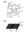
- FIG. 2 shows a conceptual diagram of the processing apparatus for basic experiment.
- the processing apparatus includes an upwardly-open chemical tank 12 which has a processing sample 10 fixed on the bottom and which is to be filled with a chemical solution, a drive mechanism 14 for reciprocating the chemical tank 12 in one direction, and a coin-shaped catalyst 16 which is to make contact with a surface (surface to be processed) of the processing sample 10, fixed on the bottom of the chemical tank 12, at a predetermined pressure.
- the coin-shaped catalyst 16 at the lower end makes point contact with the surface of the processing sample 10, and the processing sample 10 reciprocates in a horizontal direction, so that the coin-shaped catalyst 16 can in-depth linearly process of the surface of the processing sample 10 (groove processing).
- the processing sample 10 composed of GaN, immersed in the hydrofluoric acid was reciprocated at 10 mm/sec while keeping the coin-shaped catalyst 16 in contact with the surface of the processing sample 10, thereby carrying out groove-processing of the surface of the processing sample (GaN) 10 for 3 hours.
- FIGS. 3 and 4 show a perspective view of the surface of the processing sample after processing
- FIG. 4 shows a cross-sectional profile of the processing sample after processing.
- FIGS. 3 and 4 there were two linear grooves (recesses) formed in the surface of the GaN processing sample, which grooves had been processed by the contact of the surface to be processed with the coin-shaped molybdenum catalyst. This demonstrates that GaN is processible with the coin-shaped molybdenum catalyst.
- Processing of the GaN processing sample 10 was carried out in the same manner as in Example 1 except for using platinum (Pt) , having a purity of 99.98%, for the coin-shaped catalyst 16.
- FIGS. 5 and 6 show a perspective view of the surface of the processing sample after processing
- FIG. 6 shows a cross-sectional profile of the processing sample after processing.
- the surface of the GaN processing sample after processing was flat with no groove (recess) formed therein. This demonstrates that GaN is not processible with the coin-shaped platinum catalyst.
- the GaN sample for which chemical etching is generally difficult, can be easily processed only by rubbing it with the molybdenum catalyst in hydrofluoric acid (50% HF) .
- the reference plane of the coin-shaped catalyst is considered to have been transferred because of the fact that the sample was processed only in those portions just under the reference plane of the catalyst.
- Usefulness of the newly-proposed catalyst-aided chemical processing method was thus confirmed. Since hydrofluoric acid (50% HF) is inexpensive and is relatively easy to handle, this catalyst-aided chemical processing method may be useful also from a practical viewpoint.
- F radicals for example, are highly active, and it is therefore difficult to produce a sufficient amount of F radicals only by dissociation and adsorption by the catalytic action of, e.g., molybdenum.
- a voltage between a molybdenum catalyst and a workpiece when using hydrofluoric acid (aqueous HF solution) as a processing liquid, the HF dissociation reaction can be promoted to increase the amount of halogen atoms generated at the catalyst surface, thereby increasing the processing rate.
- FIGS. 7A through 7D are conceptual diagrams illustrating a processing method which employs hydrofluoric acid (aqueous HF solution) as a processing liquid and applies a voltage between a catalyst 1 formed of molybdenum (Mo) and a workpiece 2 during processing of a surface of the workpiece 2.
- the processing method uses a power source 40 whose anode and cathode are reversible.
- a conducting wire 44a extending from one pole of the power source 40 and having a switch 42 interposed therein is connected to the catalyst 1, and a conducting wire 44b extending from the other pole of the power source 40 is connected to the workpiece 2.
- the other features of the present processing method are the same as the processing method illustrated in FIGS. 1A through 1C .
- the HF 6 is dissociated at a surface of the catalyst 1 to generate H atoms 7 and halogen radicals (F radicals) 8, as shown in FIG. 7A .
- the switch 42 is then turned ON to apply such a voltage between the catalyst 1 and the workpiece 2 as to make the catalyst 1 an anode, as shown in FIG. 7B , the surface (facing the workpiece 2) of the catalyst 1 becomes an activated region 1a and the dissociation reaction of the HF 6 at the surface of the catalyst 1 is promoted to generate a large amount of F radicals 8.
- the dissolution reaction ceases because the F radicals generated at the surface of the catalyst 1 do not act on the surface of the workpiece 2 any more. Further, when the switch 42 is turned OFF, the surface of the catalyst 1 is not an activated region any more. Accordingly, the surface to be processed of the workpiece 2 is processed only when the catalyst 1 is in contact with or in close proximity to the workpiece 2.
- FIG. 8 shows a conceptual diagram of the processing apparatus for basic experiment. This processing apparatus differs from the processing apparatus shown in FIG. 2 in that this apparatus is designed to be capable of applying a voltage between a processing sample 10 and the coin-shaped catalyst 16 by a power source 18. The other constructions of this apparatus are the same as the processing apparatus shown in FIG. 2 .
- a voltage of 1V was applied between the processing sample 10 and the coin-shaped catalyst 16 with the coin-shaped catalyst 16 as an anode (Example 2).
- FIGS. 9 and 10 show a perspective view of the surface of the processing sample after processing
- FIG. 10 shows a cross-sectional profile of the processing sample after processing.
- a groove having a depth of about 200 nm was processed in the surface of the processing sample.
- FIG. 11 shows a perspective view of the surface of the processing sample (SiC) before processing
- FIG. 12A shows a perspective view of the surface of the processing sample after processing
- FIG. 12B shows an enlarged view of a portion of FIG. 12A
- FIG. 13 shows a cross-sectional profile of the processing sample after processing.
- a groove having a depth of about 175 nm was processed in the surface of the processing sample.
- the processing rate of the SiC processing sample 10 can be increased by applying a voltage of 1V between the processing sample 10 and the coin-shaped catalyst 16 with the coin-shaped catalyst 16 as an anode in carrying out processing of the processing sample 10.
- FIGS. 14 and 15 show a perspective view of the surface of the processing sample after processing
- FIG. 15 shows a cross-sectional profile of the processing sample after processing. A groove having a depth of about 200 to 250 nm was processed in the surface of the processing sample.
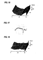
- FIGS. 16 and 17 show a perspective view of the surface of the processing sample after processing
- FIG. 17 shows a cross-sectional profile of the processing sample after processing. A groove having a depth of about 200 to 250 nm was processed in the surface of the processing sample.
- the voltage applied between the catalyst and the workpiece is preferably about 3V which corresponds to the standard electrode voltage of the HF decomposition reaction.
- FIGS. 18 and 19 show a perspective view of the surface of the processing sample after processing
- FIG. 19 shows a cross-sectional profile of the processing sample after processing. A groove having a depth of about 100 nm was processed in the surface of the processing sample.
- FIGS. 20 and 21 show a perspective view of the surface of the processing sample after processing
- FIG. 21 shows a cross-sectional profile of the processing sample after processing. A groove having a depth of about 80 nm was processed in the surface of the processing sample.
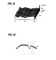
- FIGS. 22 and 23 show a perspective view of the surface of the processing sample after processing
- FIG. 23 shows a cross-sectional profile of the processing sample after processing, A groove having a depth of about 100 nm was processed in the surface of the processing sample.
- the processing rate of the SiC workpiece can be made higher by applying a voltage between the catalyst and the workpiece with the catalyst as an anode, as compared to the case of not applying a voltage.
- the processing rate of the SiC workpiece is lowered by applying a voltage between the catalyst and the workpiece with the catalyst as a cathode.
- the application of a high voltage can worsen the surface configuration of the processed workpiece.
- hydrofluoric acid is used as a processing liquid and molybdenum is used as a catalyst, and a surface of a workpiece is processed while applying a voltage between the catalyst and the workpiece.
- a surface of a workpiece while applying a voltage between a catalyst and the workpiece, it is also possible to use platinum, gold, a ceramic solid catalyst or a molybdenum alloy as the catalyst instead of molybdenum.
- platinum, gold, etc. make the surface (facing a workpiece) of the catalyst an activated region, as with the above-described embodiment illustrated in FIG. 7B , so as to promote the dissociation reaction of a halide and produce a large amount of halogen radicals, thereby increasing the processing rate.
- a wide band gap material such as GaN or SiC, is very stable chemically. It is therefore difficult to obtain a sufficiently high processing rate of the material even when it is reacted with halogen atoms as produced thorough dissociation and adsorption by the catalytic action of molybdenum.
- the processing rate of a workpiece of such a material can be increased by irradiating the surface (surface to be processed) of the workpiece with light during the reaction so as to activate the surface to be processed.
- the wavelength of the irradiating light is preferably not more than a wavelength which corresponds to the band gap of the workpiece, for example, not more than 383 nm when processing SiC, because the band gap of 4H-SiC is 3.26 eV, and not more than 365 nm when processing GaN, because the band gap of GaN is 3.42 eV.
- FIGS. 24A through 24C are conceptual diagrams illustrating a processing method which uses hydrofluoric acid (aqueous HF solution) as a processing liquid and molybdenum (Mo) as a catalyst 1, respectively, and irradiates a surface (surface to be processed) of a workpiece 2 with light during processing of the surface of the workpiece 2.
- a light source 50 is provided above the catalyst 1, and an excitation light transmissive window 52 is provided between the catalyst 1 and the light source 50.
- a large number of light passing holes 1b which vertically penetrate the catalyst 1 and permit passage of light therethrough, are provided in the catalyst 1.
- the other features of this processing method are the same as the processing method illustrated in FIGS.
- the excitation light transmissive window 52 that is transparent to light from the light source 1, the light source 50 can be prevented from being corroded by the processing liquid in which hydrogen fluoride (HF) is dissolved.
- HF hydrogen fluoride
- a fluoride glass, such as CaF 2 is preferably used for the excitation light transmissive window 52.
- hydrofluoric acid is used as a processing liquid and molybdenum is used as a catalyst, and a surface (surface to be processed) of a workpiece is processed while irradiating the surface to be processed with light.
- a surface (surface to be processed) of a workpiece while irradiating the surface to be processed with light it is also possible to use platinum, gold, a ceramic solid catalyst or a molybdenum alloy as a catalyst instead of molybdenum. It is possible also with such a catalyst to make the surface to be processed of the workpiece an excited portion activated by light excitation, as illustrated in FIG. 24A , thereby increasing the processing rate.
- the present processing method is based on a chemical reaction. It is therefore possible to control the processing rate of a workpiece by controlling the reaction temperature of the chemical reaction.
- the reaction temperature can be controlled by controlling at least one of the temperature of the workpiece, the temperature of the processing liquid, and the temperature of the catalyst.
- FIG. 25 shows a schematic perspective view of a catalyst-aided chemical processing apparatus, adapted for use as a polishing apparatus, according to an embodiment of the present invention.
- the polishing apparatus (catalyst-aided chemical processing apparatus) 20 includes a vessel 24 which is to be filled with a processing liquid 22, a catalyst platen 26 formed of molybdenum or a molybdenum alloy, rotatably disposed in the vessel 24, and a holder 30 for detachably holding a workpiece 28 with its front surface (surface to be processed) facing downwardly.
- the holder 30 is formed of a material, such as SiC, having excellent processibility, chemical resistance and temperature resistance, though it may also be formed of hard vinyl chloride or PEEK, and is coupled to the front end of a vertically-movable rotating shaft 32 provided parallel and eccentric to the rotation axis of the catalyst platen 26.
- the holder 30 is supported pivotably with respect to the rotating shaft 32 (via a ball bearing) so that the workpiece-holding face of the holder 30 can follow the surface of the catalyst platen 26 and the entire surface of the workpiece 28 can make contact with the catalyst platen 26.
- the vessel 24 is filled with the processing liquid 22, and the catalyst platen 26 and the workpiece 28 held by the holder 30 are rotated while pressing the workpiece 28 against the catalyst platen 26 at a predetermined pressure to process and flatten the surface (lower surface) of the workpiece 28.
- Grooves arranged in a net-like pattern, in a pattern of concentric circles or in a spiral pattern may be provided in the surface of the catalyst platen 26 so that, as the catalyst platen 26 rotates, a fresh processing liquid can be supplied to the processing area.
- the surface of the workpiece 28, such as a SiC wafer, is processed by using molybdenum (Mo) or a molybdenum alloy as a material for the catalyst platen 26 and using hydrofluoric acid or a solution, in which halogen-containing molecules are dissolved, as the processing liquid 22.
- Mo molybdenum
- hydrofluoric acid or a solution, in which halogen-containing molecules are dissolved as the processing liquid 22.
- Processing and flattening of the same processing sample, the SiC wafer, was carried out in the same manner as in Example 8 except for using platinum (Pt) having a purity of 99.98% as a material for the catalyst platen 26.
- the weight of the processing sample (SiC wafer) was measured before and after the processing. As a result, the weight of the processing sample was 2.4310g before the processing and 2.4308g after the processing. The processing amount was thus found to be 0.0002g that corresponds to 0.3 ⁇ m in terms of a thickness of the SiC wafer.
- the use of molybdenum for the catalyst platen 26 in the processing (polishing) of the SiC wafer can increase the processing rate by about 6 times. This is considered to be due to the fact that the reaction of dissociation of HF into H atom and F radical is more likely to occur on the surface of the molybdenum catalyst platen 26 than on the platinum catalyst platen 26.
- FIG. 26 shows a schematic perspective view of a catalyst-aided chemical processing apparatus, adapted for use as a polishing apparatus, according to another embodiment of the present invention.
- the polishing apparatus (catalyst-aided chemical processing apparatus) 20a shown in FIG. 26 differs from the polishing apparatus (catalyst-aided chemical processing apparatus) 20 shown in FIG. 25 in that the polishing apparatus 20a is provided with a power source 34 whose anode and cathode are reversible, and a conducting wire 38a extending from one pole of the power source 34 and having a switch 36 interposed therein is connected to the catalyst platen 26, and a conducting wire 38b extending from the other pole of the power source 34 is connected to a workpiece 28.
- a power source 34 whose anode and cathode are reversible
- a conducting wire 38a extending from one pole of the power source 34 and having a switch 36 interposed therein
- a conducting wire 38b extending from the other pole of the power source
- an excitation light transmissive window which is transparent to light from the light source, may be interposed between the light source and a processing liquid in which hydrogen fluoride (HF), for example, is dissolved, so as to prevent the light source from being corroded by the processing liquid.
- HF hydrogen fluoride
- a fluoride glass, such as CaF 2 is preferably used for the excitation light transmissive window.
- the vessel 24 is filled with the processing liquid 22, and the catalyst platen 26 and the workpiece 28 held by the holder 30 are rotated while pressing the workpiece 28 against the catalyst platen 26 at a predetermined pressure to process and flatten the surface (lower surface) of the workpiece 28.
- a predetermined voltage is applied between the catalyst platen 26 and the workpiece 28 with the catalyst platen 26, for example, as an anode.
- the surface (surface to be processed) of the workpiece 28 is irradiated with light having a predetermined wavelength.
- FIG. 27 shows a schematic perspective view of a catalyst-aided chemical processing apparatus, adapted for use as a polishing apparatus, according to yet another embodiment of the present invention.
- the polishing apparatus (catalyst-aided chemical processing apparatus) 20b shown in FIG. 27 differs from the polishing apparatus (catalyst-aided chemical processing apparatus) 20 shown in FIG. 25 in the following respects: Embedded in the holder 30 and extending in the rotating shaft 32, there is provided a heater 70 as a temperature control mechanism for controlling the temperature of a workpiece 28 held by the holder 30.
- a processing liquid supply nozzle 74 as a temperature control mechanism for supplying a processing liquid, whose temperature is controlled at a predetermined temperature by a heat exchanger 72, into the vessel 24.
- a fluid passage 76 as a temperature control mechanism for controlling the temperature of the catalyst platen 26 is provided in the interior of the catalyst platen 26.
- the heater 70 as a temperature control mechanism for controlling the temperature of the workpiece 28
- the processing liquid supply nozzle 74 as a temperature control mechanism for controlling the temperature of the processing liquid
- the fluid passage 76 as a temperature control mechanism for controlling the temperature of the catalyst platen 26
- in addition to molybdenum or a molybdenum alloy it is also possible to use platinum, gold or a ceramic solid catalyst for the catalyst platen 26 in this embodiment.
- the reaction temperature can be controlled by controlling at least one of the temperature of the workpiece 28, the temperature of the processing liquid and the temperature of the catalyst platen 26, whereby the processing rate can be changed.
- the first catalyst-aided chemical processing method of the present invention can be applied not only to uniaxial processing or two-dimensional processing but to various types of removal processing, including processing of a three-dimensional workpiece into a desired shape as by bringing a spherical or cylindrical catalyst into contact with the workpiece.
- the above-described voltage application, light irradiation and temperature control may be employed either singly or in a desired combination to promote processing.
- a catalyst composed of molybdenum (Mo) or a molybdenum alloy serves as a processing reference plane
- halogen-containing molecules in a processing liquid are dissociated at the surface of the catalyst to generate halogen radicals
- the halogen radicals and OH radicals generated by the decomposition of water molecules caused by the halogen radicals, act on the surface to be processed of a workpiece, whereby processing of the workpiece progresses.
- molybdenum or a molybdenum compound which performs a catalytic function, is brought into contact with or close proximity to a surface to be processed in a processing liquid, without using abrasive grains or a polishing material, and the molybdenum or molybdenum compound and the surface to be processed are moved relative to each other, whereby processing progresses while a new surface to be processed emerges continually.
- the radicals generated at the surface of the catalyst rapidly become inactive as they leave the catalyst surface.
- the radicals exist only on or in the vicinity of the catalyst surface serving as a reference plane. This makes it possible to process a workpiece in a spatially-controlled condition.
- the first catalyst-aided chemical processing method of the present invention is a chemical processing method that utilizes a reference plane, highly effective processing and flattening of a surface to be processed having a space wavelength range of not less than several tens of ⁇ m, which has been difficult with EEM or plasma CVM, becomes possible.
- the present processing method makes it possible to process with high precision not only Si but also SiC, GaN, and even sapphire, ruby and diamond which have heretofore been difficult to process.
- the present processing method can therefore be expected to be usable in semiconductor device manufacturing processes.
- the first catalyst-aided chemical processing method of the present invention thus uses a platinum, gold or a ceramic solid catalyst, molybdenum or a molybdenum compound for a processing reference plane, and processes a workpiece by generating halogen radicals through dissociation of halogen-containing molecules, dissolved in a processing liquid, at the surface of the catalyst, and dissolving in the processing liquid a halogen compound formed by a chemical reaction between a halogen radical and a surface atom of the workpiece in contact with or close proximity to the catalyst.
- a hydrohalic acid in which a workpiece normally is insoluble or hardly soluble, may therefore be used as the processing liquid.
- the halogen radicals generated at the surface of the catalyst, rapidly become inactive as they leave the surface of the catalyst.
- the halogen radicals exist only on or in the vicinity of the catalyst surface which serves as a reference plane.
- the present processing method can therefore be a chemical processing method in which processing progresses only just under the reference plane of the catalyst.
- hydrofluoric acid is used as a processing liquid and platinum is used as a catalyst in the first catalyst-aided chemical processing method of the present invention
- a wetting improver can be added to the processing liquid, hydrofluoric acid, so as to effectively supply the processing liquid to the catalyst surface.
- Nitric acid or ethanol may be preferably used as a wetting improver.
- oxides when combined with oxygen. These oxides have either the nature of a Brensted acid, the nature of a Brensted base or both the natures of Brensted acid and base, and such oxides are called an acidic oxide, a basic oxide and an amphoteric oxide, respectively.
- copper, nickel, etc. form a basic oxide
- tungsten, etc. form an acidic oxide
- aluminum, titanium, iron, gallium, etc. form an amphoteric oxide.
- An acidic oxide is an oxide which reacts with a base
- a basic oxide is an oxide which reacts with an acid
- an amphoteric oxide is an oxide which reacts both with an acid and with a base.
- An oxide, when reacted with an acid or a base becomes an ion and dissolves in a liquid.
- copper combines with oxygen to form copper oxide (CuO) which is a basic oxide, and the copper oxide reacts with an acid (H + ) and becomes copper ion in accordance with the following chemical formula (3) and dissolves in a liquid: CuO s + 2 ⁇ H + aq ⁇ Cu 2 + aq + H 2 ⁇ O
- Tungsten combines with oxygen to form tungsten oxide (W0 3 ) which is an acidic oxide, and the tungsten oxide reacts with a base (OH-) and becomes tungstate ion in accordance with the following chemical formula (4) and dissolves in a liquid: WO 3 s + 2 ⁇ OH - aq ⁇ WO 4 2 - aq + H 2 ⁇ O
- Aluminum combines with oxygen to form aluminum oxide (Al 2 0 3 ) which is an amphoteric oxide, and the aluminum oxide either reacts with an acid (H 1 ) and becomes aluminum ion in accordance with the following chemical formula (5) and dissolves in a liquid, or reacts with a base (OH - ) and becomes aluminate ion in accordance with the following chemical formula (6) and dissolves in a liquid: Al 2 ⁇ O 3 s + 6 ⁇ H + aq ⁇ 2 ⁇ Al 3 + aq + 3 ⁇ H 2 ⁇ O Al 2 ⁇ O 3 s + 3 ⁇ H 2 ⁇ O ⁇ + 2 ⁇ O ⁇ H - aq ⁇ 2 ⁇ A ⁇ l ⁇ O ⁇ H 4 - aq
- An acidic or basic solid catalyst for example, a non-woven fabric having an ion exchange function, shows an acidic or basic nature at a surface of the catalyst.
- a basic oxide of, e.g., copper or nickel, or an amphoteric oxide of, e.g., aluminum or gallium is brought into contact with or proximity to a solid catalyst which shows an acidic nature (acidic solid catalyst), such an oxide reacts with an acid (H + ion) and becomes an ion, and dissolves in a liquid.
- a surface of a copper workpiece for example, can be processed by putting the workpiece in an oxidizing processing liquid, such as ozone water, to oxidize a surface of the workpiece, and bringing the oxide into contact with or close proximity to an acidic solid catalyst to convert the surface oxide into copper ion and dissolve it in the processing liquid.
- an oxidizing processing liquid such as ozone water
- an acidic oxide of, e.g., tungsten, or an amphoteric oxide of, e.g., aluminum or gallium is brought into contact with or proximity to a solid catalyst which shows a basic nature (basic solid catalyst)
- a solid catalyst which shows a basic nature (basic solid catalyst)
- such an oxide reacts with a base (OH- ion) and becomes an ion, and dissolves in a liquid.
- a surface of a tungsten workpiece for example, can be processed by putting the workpiece in an oxidizing processing liquid, such as ozone water, to oxidize the surface of the workpiece, and bringing the oxide into contact with or close proximity to a basic solid catalyst to convert the surface oxide into tungstate ion and dissolve it in the processing liquid.
- the second catalyst-aided chemical processing method of the present invention which involves the use of an oxidizing processing liquid to process, e.g., a copper surface, will now be outlined with reference to FIGS. 28A through 28D .
- a vessel 110 is filled with an oxidizing processing liquid 112, for example, ozone water having a concentration of 4 ppm, and a workpiece 114, at least a surface of which is composed of copper, is immersed in the processing liquid 112.
- a solid catalyst having an acidic nature (acidic solid catalyst) 116 is immersed in the oxidizing processing liquid 112 and disposed at the top of the vessel 110.
- a large amount of hydrogen ions (H + ) 116a are generated at the surface of the acidic solid catalyst 116, while the surface of the workpiece (copper) 114 is oxidized by the oxidizing processing liquid 112 to form copper oxide (CuO) 114a, which is a basic oxide, in the surface of the workpiece 114, as shown in FIG. 28B .
- the surface of the acidic solid catalyst 116 is then brought into contact with the surface of the copper oxide 114a, e.g., at a pressure of about 0.01 to 5 kgf/cm 2 , as shown in FIG. 28C , whereupon the copper oxide (CuO) 114a makes etching reaction with the hydrogen ions (H + ) 116a, generated at the surface the acidic solid catalyst 116, in the contact portions A with the acidic solid catalyst 116 and becomes copper ions (Cu 2+ ), as shown by the above-described chemical formula (3), and dissolves in the oxidizing processing liquid 112.
- the portions 118 of the copper oxide 114a, which have made contact with the surface of the acidic solid catalyst 116 have thus been removed, as shown in FIG. 28D .
- the surface of the copper workpiece 114 is processed in this manner.
- the etching reaction occurs only in the contact portions A of the workpiece 114 with the acidic solid catalyst 116, whereby only the contact portions A are processed. Processing and flattening of the surface of the workpiece 114 with the surface of the acidic solid catalyst 116 as a reference plane thus becomes possible. Further, there is no acidic or basic solution remaining on the surface of the workpiece after processing. This can eliminate the need for replacement, e.g., with ultrapure water.
- the present catalyst-aided chemical processing method hydrogen ions 116a as reaction species are produced only on the surface of the acidic solid catalyst 116 and the physical properties of the surface of the acidic solid catalyst 116 do not change over a long time period. Therefore, unlike chemical etching, a surface to be processed can be processed without being influenced by the surface indices of the processing surface and a crystal fault in the surface. Since the present chemical processing method involves transfer of the reference plane, the surface of the acidic solid catalyst 116, atomic-level flattening of a surface to be processed as in EEM can be expected. Furthermore, the reference plane will not change with the progress of processing and with transfer of the reference plane. The present catalyst-aided chemical processing method can therefore be expected to be an efficient ultraprecision processing method.
- a hydrogen peroxide solution may be used as the oxidizing processing liquid 112.
- ozone water is used as the oxidizing processing liquid 112
- the use of a higher ozone concentration provides a higher oxidation rate for the workpiece 114.
- the ozone concentration of ozone water is preferably determined such that the oxidation rate of ozone water is lower than the etching rate of the acidic solid catalyst 116.
- the acidic solid catalyst 116 is composed of, for example, an acidic ion exchanger, glass, or a metal oxide having an acidic nature, for example, a ceramic such as alumina, zirconia or silicon oxide .
- an acidic ion exchanger is used as the acidic solid catalyst 116, the etching rate for the workpiece 114 can be increased by increasing the acidic ion exchange capacity of the acidic solid catalyst 116.
- the ozone concentration of ozone water is preferably balanced with the ion exchange capacity of the acidic solid catalyst 116 so that an oxide film will not grow on the workpiece 114.
- FIGS. 28A through 28D can process, in addition to copper, nickel whose oxide is basic and aluminum, titanium, iron, gallium, etc. whose oxides are amphoteric.
- tungsten, etc. whose oxides are basic as well as aluminum, titanium, iron, gallium, etc. whose oxides are amphoteric can be processed by using a solid catalyst having a basic nature (basic solid catalyst) instead of the acidic solid catalyst 116.
- the acidic solid catalyst 116 is brought into contact with the workpiece 114, it is also possible to bring the acidic solid catalyst 116 into close proximity to the workpiece 114,
- FIG. 29 shows a conceptual diagram of the processing apparatus for basic experiment.
- the processing apparatus includes a vessel 120 which has at its top a liquid inlet 120a, a liquid outlet 120b and an opening 120c, and which is to be filled with an oxidizing processing liquid 122, e.g., ozone water having a concentration of 4 ppm, and a holder 126, disposed in the opening 120c of the vessel 120, for holding a copper-plated sample 124 in the lower surface.
- an oxidizing processing liquid 122 e.g., ozone water having a concentration of 4 ppm
- a rotator 128 that rotates in a vertical plane is disposed in the vessel 120, and a solid catalyst having an acidic nature (acidic solid catalyst) 130 is fixed on the peripheral surface of the rotator 128.
- the acidic solid catalyst 130 is composed of, for example, a non-woven fabric of polyethylene fibers, having an acidic ion exchange function imparted by graft polymerization.
- FIG. 30 shows a perspective view of the copper-plated sample 124 after the processing. As shown in FIG. 30 , there was a concave processed recess formed in the surface of the copper-plated sample 124, indicating processibility of copper. No etch pit was observed in the processed surface of the sample 124. This is considered to be due to the fact that only the portion of the sample 124 in contact with the acidic solid catalyst 130 was selectively etched.
- Processing of the surface copper of the same copper-plated sample 124 was carried out in the same manner as in Example 9 except for using a non-woven fabric having no ion exchange function instead of the acidic solid catalyst 130 (Comp. Example 3), using a solid catalyst having a basic nature (basic solid catalyst) instead of the acidic solid catalyst 130 (Comp. Example 4), and using pure water instead of the oxidizing processing liquid 122 (Comp. Example 5)
- FIGS. 31A through 31C show perspective views of the copper-plated samples after processing, with FIG. 31A corresponding to Comp. Example 3, FIG. 31B corresponding to Comp. Example 4, and FIG. 31C corresponding to Comp. Example 5.
- FIGS. 31A through 31C show perspective views of the copper-plated samples after processing, with FIG. 31A corresponding to Comp. Example 3, FIG. 31B corresponding to Comp. Example 4, and FIG. 31C corresponding to Comp. Example 5.
- the processed surfaces of the copper-plated samples were flat with no formation of processed recess. This indicates that copper cannot be processed by the methods of Comp. Examples 3 to 5.
- a vessel 110 is filled with a processing liquid 112a.
- the processing liquid 112a preferably is an oxidizing processing liquid, for example, ozone water having a concentration of 4 ppm, ultrapure water or oxygen water (ultrapure water containing a high concentration of dissolved oxygen) may also be used.
- a workpiece 114 at least a surface of which is composed of copper, is immersed in the processing liquid 112a.
- a solid catalyst having an acidic nature (acidic solid catalyst) 116 having therein a large number of light passing holes 116b that vertically penetrate the catalyst 116 and permit passage of light therethrough, is immersed in the processing liquid 112a and disposed at an upper position in the vessel 110. Further, a light source 119 is disposed at a position above the acidic solid catalyst 116 at which the light source is not in contact with the processing liquid 112a.
- the wavelength of the irradiating light is preferably not more than a wavelength which corresponds to the band gap of the workpiece, for example, not more than 383 nm when processing SiC, because the band gap of 4H-SiC is 3.26 eV, and not more than 365 nm when processing GaN, because the band gap of GaN is 3.42 eV.
- the surface to be processed can be oxidized to form copper oxide (CuO) 114a, which is a basic oxide, in the surface of the workpiece 114, as shown in FIG. 32B .
- the formation of the basic copper oxide (CuO) 114a can be promoted by using as the processing liquid 112a an oxidizing processing liquid, such as ozone water having a concentration of, e.g., 4ppm.
- the surface of the acidic solid catalyst 116 is brought into contact with the surface of the copper oxide 114a, e.g., at a pressure of about 0.01 to 5 kgf/cm 2 , as shown in FIG. 32C , whereupon the copper oxide (CuO) 114a makes etching reaction with hydrogen ions (H + ) 116a, generated at the surface the acidic solid catalyst 116, in the contact portions A with the acidic solid catalyst 116 and becomes copper ions (Cu2'), as shown by the above-described chemical formula (3), and dissolves in the processing liquid 112a.
- the portions 118 of the copper oxide 114a, which have made contact with the surface of the acidic solid catalyst 116 have thus been removed, as shown in FIG. 32D .
- the surface of the copper workpiece 114 is processed in this manner.
- the etching reaction occurs only in the contact portions A of the workpiece 114 with the acidic solid catalyst 116 whereby only the contact portions A are processed. Processing and flattening of the surface of the workpiece 114 with the surface of the acidic solid catalyst 116 as a reference plane thus becomes possible. Further, hydrogen ions 116a as reaction species are produced only on the surface of the acidic solid catalyst 116 and the physical properties of the surface of the acidic solid catalyst 116 do not change over a long time period.
- the acidic solid catalyst 116 is brought into contact with the workpiece 114, it is also possible to bring the acidic solid catalyst 116 into close proximity to the workpiece 114. It is also possible to disperse an acidic solid catalyst in a powdery form in a processing liquid and supply the powder to a surface to be processed of a workpiece by a flow of the processing liquid.
- FIGS. 33A through 33D illustrate an embodiment in which the technique of voltage application is applied to the embodiment shown in FIGS. 28A through 28D .
- this embodiment uses a power source 160 whose anode and cathode are reversible.
- a conducting wire 164a extending from one pole of the power source 160 and having a switch 162 interposed therein is connected to the solid catalyst 116, and a conducting wire 164b extending from the other pole of the power source 160 is connected to the workpiece 114.
- the other features of this embodiment are the same as the embodiment illustrated in FIGS. 28A through 28D .
- the surface of the acidic solid catalyst 116 is then brought into contact with the surface of the copper oxide 114a, e.g., at a pressure of about 0.01 to 5 kgf/cm 2 , as shown in FIG. 33C , whereupon the copper oxide (CuO) 114a makes etching reaction with the hydrogen ions (H + ) 116a, generated at the surface the acidic solid catalyst 116, in the contact portions A with the acidic solid catalyst 116 and becomes copper ions (Cu 2+ ), as shown by the above-described chemical formula (3), and dissolves in the oxidizing processing liquid 112.
- the portions 118 of the copper oxide 114a, which have made contact with the surface of the acidic solid catalyst 116, have thus been removed, as shown in FIG. 33D .
- the surface of the copper workpiece 114 is processed in this manner.
- FIGS. 32A through 32D It is, of course, possible also in the embodiment shown in FIGS. 32A through 32D to apply a voltage between the solid catalyst and the surface to be processed of the workpiece to promote oxidation of the surface to be processed.
- the present processing method is based on a chemical reaction. It is therefore possible to control the processing rate of a workpiece by controlling the reaction temperature of the chemical reaction.
- the reaction temperature can be controlled by controlling at least one of the temperature of the workpiece, the temperature of the oxidizing processing liquid and the temperature of the solid catalyst in the embodiment shown in FIGS. 28A through 28D , and at least one of the temperature of the workpiece, the temperature of the processing liquid and the temperature of the solid catalyst in the embodiment shown in FIGS. 32A through 32D .
- a buffer solution may be added to the processing liquid.
- a buffer solution is a solution which, when added to the processing solution, prevents a change in the pH of the processing liquid.
- Ga 2 O 3 an oxide of GaN, is soluble in an acidic or basic liquid. Accordingly, when carrying out processing of GaN, the processing liquid should be adjusted to a pH of about 7 in order to prevent dissolution of Ga 2 O 3 in the processing liquid.
- the pH of the processing liquid can be adjusted by adding a buffer solution having an adjusted pH to the processing liquid.
- a buffer solution has the property of consuming H + ions or OH - ions generated.
- the use of a buffer solution can therefore shorten the survival time of H + ions or OH - ions.
- the use of a processing liquid, to which a buffer solution is added makes it possible to allow H + ions or OH - ions to exist only in close proximity to a solid catalyst, thereby processing a workpiece more flatly.
- FIGS. 34A through 34D illustrate the concept of processing of a workpiece using a processing liquid to which a buffer solution is added.
- a processing liquid 112b when an acidic solid catalyst 116 is immersed in a processing liquid 112b, hydrogen ions (H + ) 116a are generated at the surface of the acidic solid catalyst 116, and the hydrogen ions 116a leave the surface of the acidic solid catalyst 116.
- the processing liquid 112b by the addition of the buffer solution, contains a dissolved buffering agent 180.
- the hydrogen ions 116a which have left the surface of the acidic solid catalyst 116, rapidly react with the buffering agent 180 and become inactive, as shown in FIG. 34B .
- hydrogen ions 116a exist only on or in close proximity to the surface of the acidic solid catalyst 116 serving as a processing reference plane.
- the acidic solid catalyst 116 is brought into contact with or close proximity to the surface to be processed of a workpiece 114 in the processing liquid 112b containing the buffering agent 180, as shown in FIG. 34C , surface atoms of the contact portions of the workpiece 114 are dissolved by chemical reaction in the processing liquid 112b.
- hydrogen ions 116a generated at the surface of the acidic solid catalyst 116, do not act on the surface of the workpiece 114 any more whereby the dissolution reaction ceases.
- the surface to be processed of the workpiece 114 is processed only when the acidic solid catalyst 116 is in contact with or in close proximity to the surface to be processed of the workpiece 114.
- FIG. 35 shows a schematic perspective view of a catalyst-aided chemical processing apparatus, adapted for use as a polishing apparatus for processing of copper, according to yet another embodiment of the present invention.
- the polishing apparatus (catalyst-aided chemical processing apparatus) 131 includes a vessel 134 which is to be filled with an oxidizing processing liquid 132, for example, ozone water having a concentration of 2 ppm, a platen 136 rotatably disposed in the vessel 134, and a holder 140 for detachably holding a workpiece 138 with its front surface (surface to be processed) facing downwardly.
- a solid catalyst (acidic solid catalyst) 144 having an acidic nature is fixed on an upper surface of the platen 136.
- the holder 140 is composed of a material, such as SiC, having excellent processibility, chemical resistance and temperature resistance, though it may also be composed of hard vinyl chloride or PEEK, and is coupled to the front end of a vertically-movable rotating shaft 142 provided parallel and eccentric to the rotation axis of the platen 136.
- the holder 140 is supported pivotably with respect to the rotating shaft 142 (via a ball bearing) so that the workpiece-holding face of the holder 40 can follow the surface of the platen 136 and the entire surface of the workpiece 138 can make contact with the platen 136.
- the apparatus also includes a power source 150 whose anode and cathode are reversible.
- a conducting wire 154a extending from one pole of the power source 150 and having a switch 152 interposed therein is connected to the acidic solid catalyst 144, and a conducting wire 154b extending from the other pole of the power source 150 is connected to the workpiece 138.
- FIGS. 33A through 33D it is also possible to provide a large number of light passing holes in the platen 136 and dispose a light source below the platen 136, and to irradiate the surface (surface to be processed) of the workpiece 138 with light (preferably ultraviolet light) whose wavelength is preferably not more than a wavelength which corresponds to the band gap of the workpiece 138.
- light preferably ultraviolet light
- the vessel 134 is filled with the oxidizing processing liquid 132, for example, ozone water having a concentration of 2 ppm, and the acidic solid catalyst 144 and the workpiece 138 held by the holder 140 are rotated while pressing the workpiece 138 against the acidic solid catalyst 144 at a predetermined pressure, e.g., about 1 to 5 kgf/cm 2 , to process and flatten the surface (lower surface) of the workpiece 138.
- a predetermined voltage is applied between the acidic solid catalyst 144 and the workpiece 138 with the workpiece 138, for example, as an anode.
- the surface (surface to be processed) of the workpiece 138 is irradiated with light having a predetermined wavelength.
- a nozzle (not shown), disposed above the acidic solid catalyst 144, to between the acidic solid catalyst 144 and the workpiece 138.
- the oxidizing processing liquid is reused by circulation, it is preferred to purify the oxidizing processing liquid to remove sludge before reusing the processing liquid.
- an apparatus having the vertically reverse structure to that shown in FIG. 35 .
- a workpiece is disposed with its surface to be processed facing upwardly, and an acidic solid catalyst, facing the surface to be processed and disposed above the workpiece, is brought into light contact with or close proximity to the workpiece.
- the regeneration of the acidic solid catalyst may preferably be carried out by discharge of ions with a chemical solution or by discharge of ions by application of electric field.
- FIG. 35 shows a perspective view of the workpiece after the processing. As shown in FIG. 36 , the surface copper plated film of the workpiece was processed and removed without leaving a copper residue on the surface of the insulating film between interconnects. This is considered to be due to the fact that the present processing method is electroless processing, and thus the conductive properties of the base (insulating film) do not affect the processing characteristics.
- FIG. 37 shows a schematic perspective view of a catalyst-aided chemical processing apparatus, adapted for use as a polishing apparatus, according to yet another embodiment of the present invention.
- the polishing apparatus (catalyst-aided chemical processing apparatus) 131a shown in FIG. 37 differs from the polishing apparatus (catalyst-aided chemical processing apparatus) 131 shown in FIG. 35 in the following respects: Embedded in the holder 140 and extending in the rotating shaft 142, there is provided a heater 170 as a temperature control mechanism for controlling the temperature of a workpiece 138 held by the holder 140.
- a processing liquid supply nozzle 174 as a temperature control mechanism for supplying a processing liquid, whose temperature is controlled at a predetermined temperature by a heat exchanger 172, into the vessel 134.
- a fluid passage 176 as a temperature control mechanism for controlling the temperature of the acidic solid catalyst 144 fixed on the platen 136 is provided in the interior of the platen 136.
- the heater 170 as a temperature control mechanism for controlling the temperature of the workpiece 138
- the processing liquid supply nozzle 174 as a temperature control mechanism for controlling the temperature of the processing liquid
- the fluid passage 176 as a temperature control mechanism for controlling the temperature of the acidic solid catalyst 144
- the reaction temperature can be controlled by controlling at least one of the temperature of the workpiece 138, the temperature of the processing liquid and the temperature of the acidic solid catalyst 144, whereby the processing rate can be changed.
- FIG. 38 shows a catalyst-aided chemical processing apparatus, which is provided with a light source, adapted for use as a polishing apparatus, according to yet another embodiment of the present invention.
- the polishing apparatus (catalyst-aided chemical processing apparatus) includes a vessel 184 which is to be filled with a processing liquid 182 containing a buffering agent, a platen 188 coupled to the upper end of a rotating shaft 186 and rotatably disposed in the vessel 184, and a holder 192 for detachably holding a workpiece 190, such as a GaN substrate, with its surface to be processed facing downwardly.
- the holder 192 is secured to the lower end of a rotating shaft 194.
- a light source 196 is provided below the platen 188, and the platen 188 is composed of an acidic solid catalyst having good light transparency, such as quartz. Light, e.g., ultraviolet light, is emitted from the light source 196 and applied through the platen 188 to the lower surface (surface to be processed) of the workpiece 190.
- the platen 188 may also be composed of sapphire, zirconia, or the like, having good light transparency.
- FIG. 39 shows a phase-shift interferometry microscope image of the surface of the sample before processing. The surface roughness of the sample, which has been produced in the preceding processing, can be observed in FIG. 39.
- FIG. 40 shows a phase-shift interferometry microscope image of the surface of the sample after processing.
- FIG. 41 shows a phase-shift interferometry microscope image of the surface of the sample after processing.
- the surface roughness of the sample, processed with the use of the processing solution containing the buffering agent is considerably smaller than the surface roughness of the sample processed with ultrapure water containing no buffering agent.
- the second catalyst-aided chemical processing method of the present invention can be applied not only to uniaxial processing or two-dimensional processing but to various types of removal processing, including processing of a three-dimensional workpiece into a desired shape as by bringing a spherical or cylindrical catalyst into contact with the workpiece.
- the above-described voltage application, light irradiation and temperature control may be employed either singly or in a desired combination to promote processing.
- the second catalyst-aided chemical processing method of the present invention employs an acidic or basic solid catalyst to make it serve as a processing reference plane, and progresses processing by oxidizing a surface to be processed either by the use of an oxidizing processing liquid or by irradiation of the surface to be processed with light (e.g., ultraviolet light), reacting the resulting oxide with an acid (H + ion) or a base (OH - ion) on the surface of the solid catalyst, and dissolving the reacted oxide in a processing liquid, such as an oxidizing processing liquid.
- a processing liquid such as an oxidizing processing liquid.
- a solid catalyst which performs a catalytic function, is brought into contact with or close proximity to a surface to be processed in a processing liquid, such as an oxidizing processing liquid, without using abrasive grains or a polishing material, and the solid catalyst and the surface to be processed are moved relative to each other, whereby processing progresses while a new surface to be processed emerges continually.
- the solid catalyst exhibits an acidic or basic nature only at its surface, making it possible to process a workpiece in a spatially-controlled condition.
- the second catalyst-aided chemical processing method of the present invention is a chemical processing method that utilizes a reference plane, highly effective processing and flattening of a surface to be processed having a space wavelength range of not less than several tens of ⁇ m, which has been difficult with EEM or plasma CVM, becomes possible.
- the present processing method makes it possible to process with high precision not only copper but also such materials as GaN which have heretofore been difficult to process. The present processing method can therefore be expected to be usable in semiconductor device manufacturing processes.
- the processing principle of the third catalyst-aided chemical processing method of the present invention consists in: putting a workpiece in a processing liquid containing an oxidizing agent; bringing a solid catalyst, capable of decomposing the oxidizing agent, into contact with or close proximity to a surface to be processed of a workpiece; and removing a compound from the workpiece or dissolving the compound in the processing liquid, the compound being formed by a chemical reaction between an active species having a strong oxidizing power, generated on the catalyst, and a surface atom of the workpiece, thereby processing the workpiece.
- a light irradiation means for irradiating the surface to be processed of the workpiece with light during processing
- a voltage application means for applying a voltage between the surface to be processed of the workpiece and the solid catalyst during processing
- a solid catalyst temperature control means for controlling the temperature of the solid catalyst
- a workpiece temperature control means for controlling the temperature of the workpiece
- a processing liquid temperature control means for controlling the temperature of the processing liquid.
- the third catalyst-aided chemical processing method of the present invention includes a manner in which a workpiece and a solid catalyst are immersed in a processing liquid, and a manner in which a flow of a processing liquid is supplied to the contact portion of a workpiece in contact with a solid catalyst.
- FIGS. 42A and 42B illustrate the concept of the third catalyst-aided chemical processing method of the present invention.
- FIG. 42A when a solid catalyst 201 is brought into contact with or close proximity to a workpiece 202 in a processing liquid containing an oxidizing agent, an active species 203, generated at the surface of the solid catalyst 201, reacts with a surface atom 204 of the workpiece 202 to form a compound 205, while an oxidizing agent molecule 206 dissociates into an active species 203 and a residual molecule 207.
- the compound 205 is removed from the surface to be processed of the workpiece 202, while an unreacted active species 203 combines with a residual molecule 207 and becomes inactive, as shown in FIG. 42B .
- the workpiece 202 is processed only when the solid catalyst 201 is in contact with or close proximity to the workpiece 202.
- a light irradiation means, a voltage application means or a temperature control means, or a combination thereof is used in carrying out the processing.
- H 2 O 2 or O 3 may be used as the oxidizing agent.
- materials for the solid catalyst include transition metals such as Fe, Ni, Co, Cu, Cr and Ti, noble metals such as platinum and gold, metal oxide ceramics, a glass, such as quartz (SiO 2 ), sapphire (Al 2 O 3 ) and zirconia (ZrO 2 ), and a basic solid catalyst. These materials may be used either singly or in a combination of two or more.
- the present method is intended to process a material generally hard to process, such as crystalline SiC, sintered SiC, GaN, sapphire, ruby, diamond, etc., though Si may, of course, be processed. It is most preferred to use H 2 O 2 as the oxidizing agent and Fe for the solid catalyst, and process a workpiece composed of SiC, GaN or diamond by utilizing the Fenton reaction.
- a stabilizer for stabilizing an oxidizing agent may be added to the processing liquid in order to control the decomposition rate of the oxidizing agent.
- the reaction rate is so high that troublesome gas bubbles may grow during processing.
- the use of sodium silicate as a stabilizer can suppress the decomposition reaction of hydrogen peroxide, thereby preventing the growth of such gas bubbles. The catalytic reaction can thus be retarded by adding a stabilizer to the processing liquid.
- Hydrogen peroxide is decomposed to generate hydroxyl radicals in accordance with the following reaction formula (7) at a surface of a solid catalyst such as platinum, gold or a basic solid catalyst, as shown in FIG. 43 .
- a solid catalyst such as platinum, gold or a basic solid catalyst
- hydroxyl radicals are considered to be generated in accordance with the following reaction formula (8) ; M + nH 2 ⁇ O 2 ⁇ M nl + n ⁇ OH + nOH -
- the transition metal as a catalyst is considered to be ionized and dissolved in the solution, the amount of the dissolved metal is so small that the surface of the catalyst little changes.
- the hydroxyl radicals have a strong oxidizing power and are highly active, and are reactive even with chemically stable materials, such as SiC, GaN and diamond, and thus can be used for processing of such materials. Hydroxyl radicals, which have left the surface of the catalyst, will react with each other to return to hydrogen peroxide molecules, and will also react with water molecules or dissolved oxygen in the solution. The hydroxyl radicals thus lose their activity, and are finally decomposed into water molecules and oxygen molecules. Hydrogen peroxide molecules and oxygen molecules are inactive as compared to hydroxyl radicals, and do not react with the above-described chemically stable materials.
- Ozone molecules are decomposed into oxygen molecules and oxygen atoms in accordance with the following reaction formula (9) at a surface of a solid catalyst such as a metal oxide ceramic or a basic solid catalyst (ion-exchange material), as shown in FIG. 44 .
- a solid catalyst such as a metal oxide ceramic or a basic solid catalyst (ion-exchange material)
- the oxygen atoms have a strong oxidizing power and are highly active, and are reactive even with chemically stable materials, such as SiC, GaN and diamond, and thus can be used for processing of such materials.
- Oxygen atoms which have left the surface of the catalyst will either react with oxygen atoms in the solution to form ozone molecules, as shown by the following reaction formula (10), or react with each other to form oxygen molecules, as shown by the following reaction formula (11): ⁇ O ⁇ + O 2 ⁇ O 3 ⁇ O ⁇ + ⁇ O ⁇ ⁇ O 2
- Ozone molecules and oxygen molecules are inactive as compared to oxygen atoms, and do not react with the above-described chemically stable materials.
- SiC When processing a workpiece composed of SiC, a SiC surface is considered to be oxidized either by hydroxyl radicals in accordance with the following reaction formula (12) or by oxygen atoms in accordance with the following reaction formula (13), and the oxidized portion will be processed preferentially; SiC + 4 ⁇ O ⁇ ⁇ SiO 2 + CO 2 ⁇
- a GaN surface is considered to be oxidized either by hydroxyl radicals in accordance with the following reaction formula (14) or by oxygen atoms in accordance with the following reaction formula (15), and the oxidized portion will be processed preferentially: 2 ⁇ GaN + 7 ⁇ OH + 7 / 4 ⁇ O 2 ⁇ Ga 2 ⁇ O 3 + 7 / 2 ⁇ H 2 ⁇ O + 2 ⁇ NO 2 ⁇ 2 ⁇ GaN + 7 ⁇ O ⁇ ⁇ Ga 2 ⁇ O 3 + 2 ⁇ NO 2 ⁇
- Wide band gap materials such as SiC and GaN, are very stable chemically, and therefore it is difficult to obtain a sufficient processing rate for such a material even when utilizing the action of hydroxyl radicals or oxygen atoms.
- the surface of the workpiece can be activated, thereby increasing the processing rate. As shown in FIG.
- irradiation of a workpiece 210 with an excitation light is carried out by disposing an excitation light source 212 behind a solid catalyst 211, and passing an excitation light through an excitation light transmissive window 213 which is transparent to the excitation light and applying the excitation light from the back of the solid catalyst 211 to the workpiece 210.
- Quartz (SiO 2 ), sapphire (Al 2 O 3 ) or CaF 2 is preferably used as a material for the excitation light transmissive window 213.
- a plurality of through-holes 214 is provided in the solid catalyst 211 so as to pass the excitation light therethrough and irradiate the surface to be processed of the workpiece 210 with the excitation light.
- the wavelength of the irradiating excitation light is preferably not more than a wavelength which corresponds to the band gap of the workpiece, for example, not more than 383 nm when processing SiC, because the band gap of 4H-SiC is 3.26 eV, and not more than 365 nm when processing GaN, because the band gap of GaN is 3.42 eV.
- an activated region 215 in the surface to be processed of the workpiece 210 is processed by active species 216 generated in the vicinity of the surface of the solid catalyst 211, as shown in FIG. 45C .
- the decomposition reaction of H 2 O 2 with a transition metal is the one-electron reduction reaction of H 2 O 2 molecule, shown by the following reaction formula (18) (Haber-Weiss reaction), at the surface of the catalyst: H 2 ⁇ O 2 + e - ⁇ OH - + ⁇ OH
- the decomposition reaction rate can be increased by applying such a voltage as to make the potential of the catalyst negative.
- the increase in the reaction rate leads to generation of a larger amount of active species at the surface of the catalyst, resulting in increased processing rate of the workpiece.
- the present processing method is based on a chemical reaction. It is, therefore, considered possible to control or change the processing rate of a workpiece by controlling at least one of the temperature of the solid catalyst, the temperature of the workpiece and the temperature of the processing liquid.
- the rate of generation of active species can be controlled by controlling the temperature of the solid catalyst.
- the rate of reaction between surface atoms of the workpiece and active species can be controlled by controlling the temperature of the workpiece.
- FIG. 51 shows a processing apparatus which includes a flat rotary platen 231 having a surface solid catalyst capable of decomposing an oxidizing agent, and a holder 233 having a rotating shaft 234 eccentric to the rotating shaft 232 of the platen 231.
- a surface to be processed of a workpiece 230, held by the holder 233, is processed and flattened by supplying a processing liquid containing the oxidizing agent from a supply nozzle 235 to between the surface of the catalyst and the surface to be processed of the workpiece 230, and rotating the platen 231 and the workpiece 230 while pressing the workpiece 230 against the platen 231 at a predetermined pressure.
- the rotary platen 231 is provided in a vessel 231 so that the processing liquid can be recovered.
- a flow passage 237 is provided in the interior of the rotary platen 231 and a temperature-controlled fluid is circulated in the flow passage 237 so that the surface temperature of the rotary platen 231, i.e., the temperature of the solid catalyst, can be controlled.
- a heater 239 as a temperature control mechanism for controlling the temperature of the workpiece 230 held by the holder 233.
- the supply nozzle 235 is provided with a heat exchanger 238 so that the processing liquid, whose temperature is controlled at a predetermined temperature, can be supplied into the vessel 236.
- the heater 239 as a temperature control mechanism for controlling the temperature of the workpiece 230
- the supply nozzle 235 as a temperature control mechanism for controlling the temperature of the processing liquid
- the fluid passage 237 as a temperature control mechanism for controlling the temperature of the rotary platen 231
- the above-described voltage application means, light irradiation means and temperature control means may be employed either singly or in a desired combination to promote processing.
- the third catalyst-aided chemical processing method of the present invention employs a solid catalyst, which is capable of decomposing an oxidizing agent, to make it serve as a processing reference plane, and processes a workpiece by generating active species from the oxidizing agent at the surface of the catalyst, and removing or dissolving a compound formed by a chemical reaction between the active species and a surface atom of the workpiece in contact with or close proximity to the catalyst.
- a solid catalyst is brought into contact with or close proximity to a surface to be processed of a workpiece in a processing liquid containing an oxidizing agent, and an oxide, formed in the surface to be processed by a chemical reaction between active species and surface atoms of the workpiece, is removed, whereby processing progresses without the use of abrasive grains or a polishing material while a new surface to be processed emerges continually.
- the active species generated at the surface of the catalyst rapidly become inactive as they leave the catalyst surface.
- the active species exist only on or in the vicinity of the catalyst surface serving as a reference plane. This makes it possible to process a workpiece in a spatially-controlled condition.
- the third catalyst-aided chemical processing method of the present invention employs at least one of a light irradiation means for irradiating the surface to be processed of a workpiece with light during processing, a voltage application means for applying a voltage between the surface to be processed of a workpiece and a solid catalyst during processing, and a temperature control means for controlling the temperature of a catalyst, the temperature of a workpiece and/or the temperature of a processing liquid, which means may be used either singly or in a combination of two or more, in carrying out processing of the surface to be processed. This makes it possible to promote a chemical reaction involved in processing, thereby increasing the processing rate.
- the present processing method can therefore be expected to be usable in semiconductor device manufacturing processes.
- the present processing method is advantageous especially in that H 2 O 2 and 0 3 , which are easy to handle and inexpensive, can be used as an oxidizing agent.
- a considerable reduction in the processing cost can be made as compared to a method that uses HF.
- the above-described embodiment of the third catalyst-aided chemical processing method comprises: providing a flat rotary platen having a surface solid catalyst capable of decomposing an oxidizing agent, and a holder having a rotating shaft eccentric to the rotating shaft of the platen; supplying a processing liquid containing the oxidizing agent between the surface of the catalyst and a surface to be processed of a workpiece held by the holder; and rotating the platen and the workpiece while pressing the workpiece against the platen at a predetermined pressure, thereby processing and flattening the surface to be processed of the workpiece.
- this method is a chemical processing method that utilizes a reference plane, highly effective processing and flattening of a surface to be processed having a space wavelength range of not less than several tens of ⁇ m, which has been difficult with EEM or plasma CVM, becomes possible.
Landscapes
- Chemical & Material Sciences (AREA)
- Engineering & Computer Science (AREA)
- Chemical Kinetics & Catalysis (AREA)
- Organic Chemistry (AREA)
- Metallurgy (AREA)
- Materials Engineering (AREA)
- General Chemical & Material Sciences (AREA)
- Power Engineering (AREA)
- Microelectronics & Electronic Packaging (AREA)
- Manufacturing & Machinery (AREA)
- Computer Hardware Design (AREA)
- General Physics & Mathematics (AREA)
- Condensed Matter Physics & Semiconductors (AREA)
- Physics & Mathematics (AREA)
- Mechanical Engineering (AREA)
- Electrochemistry (AREA)
- Automation & Control Theory (AREA)
- Health & Medical Sciences (AREA)
- Toxicology (AREA)
- Weting (AREA)
- Catalysts (AREA)
Applications Claiming Priority (6)
| Application Number | Priority Date | Filing Date | Title |
|---|---|---|---|
| JP2006231095 | 2006-08-28 | ||
| JP2006283781 | 2006-10-18 | ||
| JP2006328515A JP2008136983A (ja) | 2006-12-05 | 2006-12-05 | 触媒支援型化学加工方法及び加工装置 |
| JP2006328331A JP2008081389A (ja) | 2006-08-28 | 2006-12-05 | 触媒支援型化学加工方法及び装置 |
| JP2006328287A JP5007384B2 (ja) | 2006-10-18 | 2006-12-05 | 触媒支援型化学加工方法及び装置 |
| EP20070016757 EP1894900A3 (de) | 2006-08-28 | 2007-08-27 | Katalysatorgestütztes chemisches Verarbeitungsverfahren und entsprechende Vorrichtung |
Related Parent Applications (1)
| Application Number | Title | Priority Date | Filing Date |
|---|---|---|---|
| EP07016757.2 Division | 2007-08-27 |
Publications (1)
| Publication Number | Publication Date |
|---|---|
| EP2381008A2 true EP2381008A2 (de) | 2011-10-26 |
Family
ID=38740486
Family Applications (2)
| Application Number | Title | Priority Date | Filing Date |
|---|---|---|---|
| EP20110006032 Withdrawn EP2381008A2 (de) | 2006-08-28 | 2007-08-27 | Katalysatorgestütztes chemisches Verarbeitungsverfahren und entsprechende Vorrichtung |
| EP20070016757 Withdrawn EP1894900A3 (de) | 2006-08-28 | 2007-08-27 | Katalysatorgestütztes chemisches Verarbeitungsverfahren und entsprechende Vorrichtung |
Family Applications After (1)
| Application Number | Title | Priority Date | Filing Date |
|---|---|---|---|
| EP20070016757 Withdrawn EP1894900A3 (de) | 2006-08-28 | 2007-08-27 | Katalysatorgestütztes chemisches Verarbeitungsverfahren und entsprechende Vorrichtung |
Country Status (2)
| Country | Link |
|---|---|
| US (2) | US7651625B2 (de) |
| EP (2) | EP2381008A2 (de) |
Cited By (1)
| Publication number | Priority date | Publication date | Assignee | Title |
|---|---|---|---|---|
| CN104745095A (zh) * | 2015-04-03 | 2015-07-01 | 清华大学 | 一种GaN厚膜片CMP组合物及其制备方法 |
Families Citing this family (28)
| Publication number | Priority date | Publication date | Assignee | Title |
|---|---|---|---|---|
| US7776228B2 (en) | 2006-04-11 | 2010-08-17 | Ebara Corporation | Catalyst-aided chemical processing method |
| US8734661B2 (en) * | 2007-10-15 | 2014-05-27 | Ebara Corporation | Flattening method and flattening apparatus |
| JP5364959B2 (ja) | 2009-03-27 | 2013-12-11 | 国立大学法人大阪大学 | 研磨方法及び研磨装置 |
| US8247328B2 (en) * | 2009-05-04 | 2012-08-21 | Cabot Microelectronics Corporation | Polishing silicon carbide |
| EP2513955A1 (de) | 2009-12-15 | 2012-10-24 | Osaka University | Polierverfahren, poliervorrichtung und polierinstrument |
| WO2011099216A1 (ja) * | 2010-02-15 | 2011-08-18 | Kobayashi Hikaru | 半導体装置の製造方法、半導体装置、並びに転写用部材 |
| JP2012035188A (ja) * | 2010-08-06 | 2012-02-23 | Hitachi Cable Ltd | 加工方法 |
| TWI555077B (zh) * | 2010-12-08 | 2016-10-21 | Hikaru Kobayashi | A manufacturing method of a semiconductor device, a manufacturing apparatus for a semiconductor device, and a semiconductor device Body device, and transfer element |
| WO2013024746A1 (ja) * | 2011-08-12 | 2013-02-21 | Kobayashi Hikaru | 半導体装置の製造方法、半導体装置の製造装置、半導体装置、半導体装置の製造プログラム、半導体用処理剤、並びに転写用部材 |
| WO2013084934A1 (ja) * | 2011-12-06 | 2013-06-13 | 国立大学法人大阪大学 | 固体酸化物の加工方法及びその装置 |
| US8952110B2 (en) * | 2012-06-21 | 2015-02-10 | Prc-Desoto International, Inc. | Moisture-curable, amine-catalyzed sulfur-containing polymer compositions |
| JP5935168B2 (ja) * | 2012-08-20 | 2016-06-15 | 東邦エンジニアリング株式会社 | 基板研磨装置 |
| WO2014104009A1 (ja) * | 2012-12-27 | 2014-07-03 | Hoya株式会社 | マスクブランク用基板処理装置、マスクブランク用基板処理方法、マスクブランク用基板の製造方法、マスクブランクの製造方法、及び転写用マスクの製造方法 |
| WO2014112409A1 (ja) * | 2013-01-18 | 2014-07-24 | Hoya株式会社 | マスクブランク用基板の製造方法、マスクブランクの製造方法及び転写用マスクの製造方法 |
| JP5820404B2 (ja) | 2013-02-05 | 2015-11-24 | 株式会社東芝 | 平坦化方法及び平坦化装置 |
| JP6016301B2 (ja) | 2013-02-13 | 2016-10-26 | 昭和電工株式会社 | 単結晶SiC基板の表面加工方法、その製造方法及び単結晶SiC基板の表面加工用研削プレート |
| CN105556642B (zh) * | 2013-07-19 | 2017-10-31 | 国立大学法人名古屋工业大学 | 金属制研磨衬垫及其制造方法 |
| US9721802B2 (en) * | 2013-10-03 | 2017-08-01 | Applied Materials, Inc. | LED based optical source coupled with plasma source |
| JP6206847B2 (ja) * | 2014-03-12 | 2017-10-04 | 国立大学法人大阪大学 | ワイドバンドギャップ半導体基板の加工方法及びその装置 |
| KR102120687B1 (ko) | 2014-04-18 | 2020-06-09 | 가부시키가이샤 에바라 세이사꾸쇼 | 기판 처리 장치, 기판 처리 시스템 및 기판 처리 방법 |
| DE112015002319B4 (de) | 2014-12-31 | 2024-07-25 | Osaka University | Planarisierungsbearbeitungsverfahren und Planarisierungsbearbeitungsvorrichtung |
| JP6346124B2 (ja) | 2015-06-02 | 2018-06-20 | 東芝メモリ株式会社 | 半導体装置の製造方法 |
| JP6438868B2 (ja) | 2015-09-16 | 2018-12-19 | 東芝メモリ株式会社 | 半導体装置の製造方法および半導体製造装置 |
| JP6187948B1 (ja) | 2016-03-11 | 2017-08-30 | 東邦エンジニアリング株式会社 | 平坦加工装置、その動作方法および加工物の製造方法 |
| US10879087B2 (en) * | 2017-03-17 | 2020-12-29 | Toshiba Memory Corporation | Substrate treatment apparatus and manufacturing method of semiconductor device |
| JP7569053B2 (ja) * | 2020-02-19 | 2024-10-17 | 学校法人 芝浦工業大学 | めっき基板 |
| US20220297223A1 (en) * | 2021-03-18 | 2022-09-22 | National University Corporation Nagaoka University Of Technology | Work processing apparatus |
| KR102609275B1 (ko) * | 2021-05-20 | 2023-12-04 | 성균관대학교산학협력단 | 광전극의 제조 방법 |
Citations (8)
| Publication number | Priority date | Publication date | Assignee | Title |
|---|---|---|---|---|
| JPH0225745A (ja) | 1988-07-14 | 1990-01-29 | Res Dev Corp Of Japan | タンパク質分子量マーカー |
| JPH0369271B2 (de) | 1986-09-09 | 1991-10-31 | Ajikan Kk | |
| JPH0644989A (ja) | 1992-03-13 | 1994-02-18 | Inst Of Gas Technol | 積層燃料電池部材 |
| JPH0716870A (ja) | 1993-06-30 | 1995-01-20 | Kinugawa Rubber Ind Co Ltd | ガラス一体型ウエザーストリップの成形金型 |
| JP2962583B2 (ja) | 1991-01-28 | 1999-10-12 | 株式会社 ユーハ味覚糖精密工学研究所 | ラジカル反応による無歪精密数値制御加工方法及びその装置 |
| JP2000167770A (ja) | 1998-12-07 | 2000-06-20 | Japan Science & Technology Corp | 高速剪断流による加工方法 |
| JP3734722B2 (ja) | 2001-05-23 | 2006-01-11 | 独立行政法人科学技術振興機構 | ダイヤモンド薄膜の化学機械研磨方法 |
| JP2006114632A (ja) | 2004-10-13 | 2006-04-27 | Kazuto Yamauchi | 触媒支援型化学加工方法 |
Family Cites Families (19)
| Publication number | Priority date | Publication date | Assignee | Title |
|---|---|---|---|---|
| US3892092A (en) * | 1974-05-17 | 1975-07-01 | Buehler Ltd | Automatic polishing apparatus |
| US5688364A (en) * | 1994-12-22 | 1997-11-18 | Sony Corporation | Chemical-mechanical polishing method and apparatus using ultrasound applied to the carrier and platen |
| US5948697A (en) * | 1996-05-23 | 1999-09-07 | Lsi Logic Corporation | Catalytic acceleration and electrical bias control of CMP processing |
| US6435947B2 (en) * | 1998-05-26 | 2002-08-20 | Cabot Microelectronics Corporation | CMP polishing pad including a solid catalyst |
| US6352466B1 (en) * | 1998-08-31 | 2002-03-05 | Micron Technology, Inc. | Method and apparatus for wireless transfer of chemical-mechanical planarization measurements |
| JP2000127033A (ja) * | 1998-10-27 | 2000-05-09 | Speedfam-Ipec Co Ltd | 研磨装置 |
| JP2001064799A (ja) * | 1999-08-27 | 2001-03-13 | Yuzo Mori | 電解加工方法及び装置 |
| US6793561B2 (en) * | 1999-10-14 | 2004-09-21 | International Business Machines Corporation | Removable/disposable platen top |
| JP4028163B2 (ja) * | 1999-11-16 | 2007-12-26 | 株式会社デンソー | メカノケミカル研磨方法及びメカノケミカル研磨装置 |
| US7335603B2 (en) * | 2000-02-07 | 2008-02-26 | Vladimir Mancevski | System and method for fabricating logic devices comprising carbon nanotube transistors |
| US20030162398A1 (en) * | 2002-02-11 | 2003-08-28 | Small Robert J. | Catalytic composition for chemical-mechanical polishing, method of using same, and substrate treated with same |
| KR100541545B1 (ko) * | 2003-06-16 | 2006-01-11 | 삼성전자주식회사 | 화학기계적 연마 장비의 연마 테이블 |
| US6848977B1 (en) * | 2003-08-29 | 2005-02-01 | Rohm And Haas Electronic Materials Cmp Holdings, Inc. | Polishing pad for electrochemical mechanical polishing |
| US6984163B2 (en) * | 2003-11-25 | 2006-01-10 | Rohm And Haas Electronic Materials Cmp Holdings, Inc. | Polishing pad with high optical transmission window |
| JP4581427B2 (ja) * | 2004-02-27 | 2010-11-17 | 富士電機システムズ株式会社 | 膜厚評価方法、研磨終点検出方法 |
| JP2006120870A (ja) * | 2004-10-21 | 2006-05-11 | Ebara Corp | 配線形成方法及び装置 |
| US8008203B2 (en) * | 2005-07-07 | 2011-08-30 | National Universtiy Corporation Kumamoto University | Substrate, method of polishing the same, and polishing apparatus |
| US7776228B2 (en) * | 2006-04-11 | 2010-08-17 | Ebara Corporation | Catalyst-aided chemical processing method |
| US7998228B2 (en) * | 2006-07-19 | 2011-08-16 | Cabot Microelectronics Corporation | Tantalum CMP compositions and methods |
-
2007
- 2007-08-27 US US11/892,780 patent/US7651625B2/en active Active
- 2007-08-27 EP EP20110006032 patent/EP2381008A2/de not_active Withdrawn
- 2007-08-27 EP EP20070016757 patent/EP1894900A3/de not_active Withdrawn
-
2009
- 2009-12-11 US US12/636,069 patent/US20100147463A1/en not_active Abandoned
Patent Citations (8)
| Publication number | Priority date | Publication date | Assignee | Title |
|---|---|---|---|---|
| JPH0369271B2 (de) | 1986-09-09 | 1991-10-31 | Ajikan Kk | |
| JPH0225745A (ja) | 1988-07-14 | 1990-01-29 | Res Dev Corp Of Japan | タンパク質分子量マーカー |
| JP2962583B2 (ja) | 1991-01-28 | 1999-10-12 | 株式会社 ユーハ味覚糖精密工学研究所 | ラジカル反応による無歪精密数値制御加工方法及びその装置 |
| JPH0644989A (ja) | 1992-03-13 | 1994-02-18 | Inst Of Gas Technol | 積層燃料電池部材 |
| JPH0716870A (ja) | 1993-06-30 | 1995-01-20 | Kinugawa Rubber Ind Co Ltd | ガラス一体型ウエザーストリップの成形金型 |
| JP2000167770A (ja) | 1998-12-07 | 2000-06-20 | Japan Science & Technology Corp | 高速剪断流による加工方法 |
| JP3734722B2 (ja) | 2001-05-23 | 2006-01-11 | 独立行政法人科学技術振興機構 | ダイヤモンド薄膜の化学機械研磨方法 |
| JP2006114632A (ja) | 2004-10-13 | 2006-04-27 | Kazuto Yamauchi | 触媒支援型化学加工方法 |
Cited By (2)
| Publication number | Priority date | Publication date | Assignee | Title |
|---|---|---|---|---|
| CN104745095A (zh) * | 2015-04-03 | 2015-07-01 | 清华大学 | 一种GaN厚膜片CMP组合物及其制备方法 |
| CN104745095B (zh) * | 2015-04-03 | 2017-06-06 | 清华大学 | 一种GaN厚膜片CMP组合物及其制备方法 |
Also Published As
| Publication number | Publication date |
|---|---|
| EP1894900A2 (de) | 2008-03-05 |
| US7651625B2 (en) | 2010-01-26 |
| EP1894900A3 (de) | 2010-02-24 |
| US20100147463A1 (en) | 2010-06-17 |
| US20080073222A1 (en) | 2008-03-27 |
Similar Documents
| Publication | Publication Date | Title |
|---|---|---|
| US7651625B2 (en) | Catalyst-aided chemical processing method and apparatus | |
| JP5007384B2 (ja) | 触媒支援型化学加工方法及び装置 | |
| JP5963223B2 (ja) | ガラス材料の加工方法及びその装置 | |
| JP2008081389A (ja) | 触媒支援型化学加工方法及び装置 | |
| JP6206847B2 (ja) | ワイドバンドギャップ半導体基板の加工方法及びその装置 | |
| JP4982742B2 (ja) | 磁性微粒子を用いた触媒化学加工方法及び装置 | |
| US6743349B2 (en) | Electrochemical machining method and apparatus | |
| JP4873694B2 (ja) | 触媒支援型化学加工方法 | |
| US6652658B1 (en) | Method for machining/cleaning by hydroxide ion in ultrapure water | |
| JP2008136983A (ja) | 触媒支援型化学加工方法及び加工装置 | |
| TWI252216B (en) | Functional water, method and apparatus of producing the same, and method and apparatus of rinsing electronic parts therewith | |
| US20050183963A1 (en) | Electrode for electrolytic processing | |
| JP2006502310A (ja) | 電解加工装置 | |
| JP6188152B2 (ja) | Si基板の平坦化加工方法及びその装置 | |
| JP2011120989A (ja) | 表面加工方法 | |
| JP2015127078A (ja) | 加工方法及び加工装置 | |
| EP1170083B1 (de) | Verfahren und Vorrichtung zum elektrochemischen Bearbeiten | |
| JP2007160496A (ja) | ワーク研磨装置およびワーク研磨方法 | |
| JP2018113366A (ja) | 触媒表面基準エッチング方法及びその装置 | |
| JP2023103839A (ja) | 半導体ウェハの表面加工方法 | |
| JP2006176885A (ja) | 超純水中の水酸基による加工方法 | |
| JP2005288580A (ja) | 電解加工方法及び装置 | |
| WO2004033765A1 (en) | Electrode for electrolytic processing | |
| JP2004299046A (ja) | 電解加工用電極、電解加工装置及び方法 | |
| JP2006159407A (ja) | 超純水中の水酸基による加工方法 |
Legal Events
| Date | Code | Title | Description |
|---|---|---|---|
| 17P | Request for examination filed |
Effective date: 20110722 |
|
| AC | Divisional application: reference to earlier application |
Ref document number: 1894900 Country of ref document: EP Kind code of ref document: P |
|
| AK | Designated contracting states |
Kind code of ref document: A2 Designated state(s): DE FR |
|
| PUAI | Public reference made under article 153(3) epc to a published international application that has entered the european phase |
Free format text: ORIGINAL CODE: 0009012 |
|
| RAP1 | Party data changed (applicant data changed or rights of an application transferred) |
Owner name: EBARA CORPORATION |
|
| STAA | Information on the status of an ep patent application or granted ep patent |
Free format text: STATUS: THE APPLICATION HAS BEEN WITHDRAWN |
|
| 18W | Application withdrawn |
Effective date: 20140722 |