EP2380405B1 - System und verfahren zur fernüberwachung und -steuerung von led-leuchten - Google Patents
System und verfahren zur fernüberwachung und -steuerung von led-leuchten Download PDFInfo
- Publication number
- EP2380405B1 EP2380405B1 EP10732010.3A EP10732010A EP2380405B1 EP 2380405 B1 EP2380405 B1 EP 2380405B1 EP 10732010 A EP10732010 A EP 10732010A EP 2380405 B1 EP2380405 B1 EP 2380405B1
- Authority
- EP
- European Patent Office
- Prior art keywords
- led
- current
- operating
- voltage
- temperature
- Prior art date
- Legal status (The legal status is an assumption and is not a legal conclusion. Google has not performed a legal analysis and makes no representation as to the accuracy of the status listed.)
- Not-in-force
Links
- 238000000034 method Methods 0.000 title claims description 118
- 239000004020 conductor Substances 0.000 claims description 204
- 230000008859 change Effects 0.000 claims description 10
- 230000006378 damage Effects 0.000 claims description 6
- 230000004044 response Effects 0.000 claims description 6
- 230000003685 thermal hair damage Effects 0.000 claims description 6
- 238000005286 illumination Methods 0.000 claims description 4
- 230000000903 blocking effect Effects 0.000 claims description 3
- 230000000284 resting effect Effects 0.000 claims description 3
- 230000016776 visual perception Effects 0.000 claims description 3
- 230000007423 decrease Effects 0.000 description 11
- 238000010586 diagram Methods 0.000 description 11
- 238000005259 measurement Methods 0.000 description 11
- 238000012544 monitoring process Methods 0.000 description 10
- 239000004065 semiconductor Substances 0.000 description 10
- 230000003287 optical effect Effects 0.000 description 8
- 230000037361 pathway Effects 0.000 description 7
- 230000001965 increasing effect Effects 0.000 description 6
- 238000009529 body temperature measurement Methods 0.000 description 4
- 238000004891 communication Methods 0.000 description 4
- 238000005215 recombination Methods 0.000 description 4
- 230000006798 recombination Effects 0.000 description 4
- 230000001131 transforming effect Effects 0.000 description 4
- 230000006399 behavior Effects 0.000 description 3
- 230000006870 function Effects 0.000 description 3
- 230000008569 process Effects 0.000 description 3
- 238000007792 addition Methods 0.000 description 2
- 230000008901 benefit Effects 0.000 description 2
- 230000015556 catabolic process Effects 0.000 description 2
- 238000001514 detection method Methods 0.000 description 2
- 238000009434 installation Methods 0.000 description 2
- 238000012986 modification Methods 0.000 description 2
- 230000004048 modification Effects 0.000 description 2
- 238000013021 overheating Methods 0.000 description 2
- OAICVXFJPJFONN-UHFFFAOYSA-N Phosphorus Chemical compound [P] OAICVXFJPJFONN-UHFFFAOYSA-N 0.000 description 1
- 238000009825 accumulation Methods 0.000 description 1
- 230000001066 destructive effect Effects 0.000 description 1
- 230000002708 enhancing effect Effects 0.000 description 1
- 238000010438 heat treatment Methods 0.000 description 1
- 238000004519 manufacturing process Methods 0.000 description 1
- 239000000463 material Substances 0.000 description 1
- 239000002184 metal Substances 0.000 description 1
- 239000002480 mineral oil Substances 0.000 description 1
- 235000010446 mineral oil Nutrition 0.000 description 1
- 239000003921 oil Substances 0.000 description 1
- 230000008447 perception Effects 0.000 description 1
- 230000002688 persistence Effects 0.000 description 1
- 230000000704 physical effect Effects 0.000 description 1
- 230000009467 reduction Effects 0.000 description 1
- 238000005070 sampling Methods 0.000 description 1
Images






Classifications
-
- H—ELECTRICITY
- H05—ELECTRIC TECHNIQUES NOT OTHERWISE PROVIDED FOR
- H05B—ELECTRIC HEATING; ELECTRIC LIGHT SOURCES NOT OTHERWISE PROVIDED FOR; CIRCUIT ARRANGEMENTS FOR ELECTRIC LIGHT SOURCES, IN GENERAL
- H05B45/00—Circuit arrangements for operating light-emitting diodes [LED]
- H05B45/50—Circuit arrangements for operating light-emitting diodes [LED] responsive to malfunctions or undesirable behaviour of LEDs; responsive to LED life; Protective circuits
- H05B45/58—Circuit arrangements for operating light-emitting diodes [LED] responsive to malfunctions or undesirable behaviour of LEDs; responsive to LED life; Protective circuits involving end of life detection of LEDs
-
- H—ELECTRICITY
- H05—ELECTRIC TECHNIQUES NOT OTHERWISE PROVIDED FOR
- H05B—ELECTRIC HEATING; ELECTRIC LIGHT SOURCES NOT OTHERWISE PROVIDED FOR; CIRCUIT ARRANGEMENTS FOR ELECTRIC LIGHT SOURCES, IN GENERAL
- H05B45/00—Circuit arrangements for operating light-emitting diodes [LED]
- H05B45/50—Circuit arrangements for operating light-emitting diodes [LED] responsive to malfunctions or undesirable behaviour of LEDs; responsive to LED life; Protective circuits
- H05B45/56—Circuit arrangements for operating light-emitting diodes [LED] responsive to malfunctions or undesirable behaviour of LEDs; responsive to LED life; Protective circuits involving measures to prevent abnormal temperature of the LEDs
-
- G—PHYSICS
- G01—MEASURING; TESTING
- G01K—MEASURING TEMPERATURE; MEASURING QUANTITY OF HEAT; THERMALLY-SENSITIVE ELEMENTS NOT OTHERWISE PROVIDED FOR
- G01K13/00—Thermometers specially adapted for specific purposes
-
- G—PHYSICS
- G01—MEASURING; TESTING
- G01K—MEASURING TEMPERATURE; MEASURING QUANTITY OF HEAT; THERMALLY-SENSITIVE ELEMENTS NOT OTHERWISE PROVIDED FOR
- G01K7/00—Measuring temperature based on the use of electric or magnetic elements directly sensitive to heat ; Power supply therefor, e.g. using thermoelectric elements
- G01K7/01—Measuring temperature based on the use of electric or magnetic elements directly sensitive to heat ; Power supply therefor, e.g. using thermoelectric elements using semiconducting elements having PN junctions
-
- H—ELECTRICITY
- H05—ELECTRIC TECHNIQUES NOT OTHERWISE PROVIDED FOR
- H05B—ELECTRIC HEATING; ELECTRIC LIGHT SOURCES NOT OTHERWISE PROVIDED FOR; CIRCUIT ARRANGEMENTS FOR ELECTRIC LIGHT SOURCES, IN GENERAL
- H05B45/00—Circuit arrangements for operating light-emitting diodes [LED]
- H05B45/10—Controlling the intensity of the light
- H05B45/14—Controlling the intensity of the light using electrical feedback from LEDs or from LED modules
-
- G—PHYSICS
- G01—MEASURING; TESTING
- G01K—MEASURING TEMPERATURE; MEASURING QUANTITY OF HEAT; THERMALLY-SENSITIVE ELEMENTS NOT OTHERWISE PROVIDED FOR
- G01K2217/00—Temperature measurement using electric or magnetic components already present in the system to be measured
Definitions
- LEDs light emitting diodes
- designers using incandescent light sources have had decades to work out problems, LEDs are relatively new and still present some issues that need to be resolved before gaining wide acceptance.
- One such issue involves the reaction of LEDs to heat.
- LEDs require a relatively low constant temperature in comparison to incandescent light sources or bulbs.
- a typical operating temperature of an incandescent filament is over 2,000 degrees Celsius.
- An LED may have a maximum operating temperature of approximately 150 degrees Celsius, and operation above this maximum can cause a decrease in the operational lifetime of the LED.
- the decrease in light output is caused at least in part by carrier recombination processes at higher temperatures and a decrease in the effective optical bandgap of the LED at these temperatures.
- a typical operating temperature of an LED is usually below about 100 degrees Celsius to preserve operational lifetime while maintaining acceptable light output.
- LEDs are typically grouped together in each light fixture to provide the amount of light output necessary for lighting a room in a home or building.
- LEDs used in light fixtures are typically considerably higher in light output and power consumption than the typical colored indicator LED seen in many electronic devices. This increase in the LED density and power causes an increase in heat buildup in the fixture.
- an increase in temperature causes an increase in current which, consequently, causes a further increase in temperature. If left unchecked, the increased current caused by increased temperature can cause thermal runaway where the temperature increases to a point where the LED is damaged. Therefore, it is important to control the power supplied to the LEDs to ensure that the temperature of the LEDs does not exceed the maximum safe operating temperature. Controlling the power to the LED can generally be accomplished by controlling the current or controlling the voltage, although light output is directly related to current.
- Incandescent and fluorescent lighting fixtures in buildings are usually supplied by a line or mains voltage, such as 115 Volts AC at 60 Hertz in the United States. Other single phase voltages are also used, such as 277 Volts AC, and in some instances other single and multiple phase voltages are used as well as other frequencies, such as in England where 220 Volts at 50 Hz is common. Power to these lighting fixtures is controlled by a wall mounted switch for an on or off operation, and a dimmer switch can be used to control brightness levels in addition to providing a simple on and off function.
- LEDs in light fixtures operate on a much lower voltage than what is typically supplied to a building. LEDs require low voltage DC so supply power must be converted from higher voltage AC to DC constant current. Generally a single white LED will require a forward voltage of less than approximately 3.5 Volts. It is also important to control current to the LED since excessive current can destroy the LED and changes in current can lead to undesirable changes in light output.
- thermocouples or thermistors to measure temperatures of the LEDs. These devices are placed in a position near the LED and are connected to a temperature monitoring system using set of wires that are in addition to the wires powering the LED. These temperature detection devices cannot directly measure the actual temperature of the LED die itself since they necessarily have to be spaced apart from the LED die because of optics of the LEDs and the LED conductors. In addition, the extra set of wires between the thermistor and the monitoring system can be inconvenient, especially if the monitoring system is a significant distance from the thermistor. Because the thermistors do not directly measure the actual temperature of the LED die, these devices introduce some particular inaccuracies into the temperature measurement.
- US2008/319690A1 discloses a method of measuring the temperature of the P-N junction within the light-emitting region of a quasi-continuous-wave or pulsed semiconductor laser diode device by applying a series of current pulses to the laser diode and measuring the resulting voltage. The temperature is determined from the measured junction voltage using a known linear relationship.
- the present invention provides a method for determining a temperature of a LED as set out in claim 1, and a control system as set out in claim 16.
- the present invention overcomes the limitations of conventional LED temperature measurement devices by providing a method and device for measuring an actual temperature of the LED not an approximation based on a temperature near the LED.
- a method for determining a temperature of at least one light emitting diode (LED) in a circuit includes a power supply for powering the LED through first and second LED conductors by providing an operating current through the LED conductors and an operating voltage across the LED conductors.
- the LED is operable to generate light in response to receiving the operating current in a range of operating currents and receiving the operating voltage in a range of operating voltages.
- An operating current and operating voltage are provided to the LED through the first and second LED conductors.
- a current pulse is superimposed on the operating current to the LED, through the first and second LED conductors resulting in a voltage pulse that is superimposed on the operating voltage.
- the voltage pulse is sensed across the first and second LED conductors resulting from the applied pulse of current to determine a voltage magnitude of the voltage pulse.
- a current magnitude of the current pulse is determined, and the operating temperature of the LED is determined based on the current magnitude of the current pulse and the voltage magnitude of the voltage pulse.
- the circuit includes a power supply for powering the LED through first and second LED conductors to cause the LED to operate to generate light when a forward operating voltage and forward operating current is supplied to the LED through the LED conductors.
- the LED exhibits a forward voltage resistance when the forward operating voltage is supplied to the LED through the LED conductors and the LED exhibits a reverse bias voltage resistance when a reverse bias voltage is supplied to the LED through the LED conductors.
- the reverse bias voltage resistance is greater than the forward voltage resistance.
- a thermistor is arranged across the first and second LED conductors in parallel with the LED.
- the thermistor has an effective resistance range in which at least two different thermistor resistances of the thermistor correspond to at least two different thermistor temperatures of the thermistor.
- the thermistor resistances in the effective resistance range are lower than the reverse bias voltage resistance of the LED and are higher than the forward voltage resistance of the LED.
- An effective resistance range is selected such that, when a forward drive current is applied to the LED conductors, one portion of the forward drive current which flows through the LED is the forward operating current and another portion of the forward drive current which flows through the thermistor is a forward thermistor current which is smaller than the forward operating current.
- a reverse drive current flows through the LED conductors in an opposite direction than the forward drive current and one portion of the reverse drive current flows as a leakage current through the LED and which does not cause the LED to produce light and another portion of the reverse drive current flows through the thermistor as a reverse thermistor current which is larger than the leakage current.
- the thermistor is positioned in a thermal pathway of the LED to receive heat produced by the LED during operation of the LED. The temperature of the thermistor is measurable by determining the thermistor resistance using the reverse thermistor current and the temperature of the thermistor is related to a temperature of the LED.
- a switch assembly for electrical communication with at least one light emitting diode (LED) assembly to control the LED assembly.
- the LED assembly has at least one LED with a first LED conductor and a second LED conductor and which is powered by receiving an operating current through the LED conductors in a range of operating currents and an operating voltage across the LED conductors in a range of operating voltages.
- the LED assembly is configured to be fixedly installed remotely from the switch assembly to provide light.
- a transformer is included for electrically connecting to a line power source for receiving line power with a line voltage greater than 100 Volts AC and converting the line voltage to a transformed power with a transformed voltage that is less than 50 Volts.
- a power controller is included for receiving the transformed power from the transformer and for at least creating an operating power with the operating current in the range of operating currents and the operating voltage in the range of operating voltages.
- the power controller is arranged to electrically connect to the LED assembly through the LED conductors to supply the operating current and operating voltage to the LED assembly through the LED conductors.
- a temperature monitor is included for electrically connecting to the LED conductors.
- the temperature monitor includes a current sensor to determine a magnitude of current through the LED conductors and a voltage sensor to determine a magnitude of voltage across the LED conductors.
- the temperature monitor also includes a controller that is electrically connected with the current and voltage sensors and is configured for calculating a temperature of the LED in the LED assembly based at least partially on the determined current and voltage magnitudes.
- a switch is also included for selectively connecting and disconnecting the operating current and operating voltage from the LED assembly.
- a control system for determining a temperature of at least one light emitting diode (LED) in a circuit which includes a power supply for powering the LED through first and second LED conductors by providing an operating current through the LED conductors and an operating voltage across the LED conductors.
- the LED is operable to generate light in response to receiving the operating current in a range of operating currents and receiving the operating voltage in a range of operating voltages.
- the control system includes a power supply for providing the operating current and operating voltage to the LED through the first and second LED conductors. The power supply is used in superimposing a current pulse on the operating current to the LED, through the first and second LED conductors resulting in a voltage pulse that is superimposed on the operating voltage.
- a voltage sensor is included for sensing the voltage pulse across the first and second LED conductors resulting from the applied pulse of current to determine a voltage magnitude of the voltage pulse.
- a current sensor is included for determining a current magnitude of the current pulse.
- a controller is included for determining the operating temperature of the LED at the provided operating current based on the current magnitude of the current pulse and the voltage magnitude of the voltage pulse.
- a control system for determining a temperature near at least one light emitting diode (LED) in a circuit.
- the circuit includes a power supply for powering the LED through first and second LED conductors to cause the LED to operate to generate light when a forward operating voltage and forward operating current is supplied to the LED through the LED conductors.
- the LED exhibits a forward voltage resistance when the forward operating voltage is supplied to the LED through the LED conductors and the LED exhibits a reverse bias voltage resistance when a reverse bias voltage is supplied to the LED through the LED conductors.
- the reverse bias voltage resistance is greater than the forward voltage resistance.
- the control system includes a thermistor that is electrically connected across the first and second LED conductors in parallel with the LED.
- the thermistor has an effective resistance range in which at least two different thermistor resistances of the thermistor correspond to at least two different thermistor temperatures of the thermistor.
- the thermistor resistances in the effective resistance range are lower than the reverse bias voltage resistance of the LED and are higher than the forward voltage resistance of the LED.
- the effective resistance range is such that, when a forward drive current is applied to the LED conductors, one portion of the forward drive current which flows through the LED is the forward operating current and another portion of the forward drive current which flows through the thermistor is a forward thermistor current which is smaller than the forward operating current.
- a reverse drive current flows through the LED conductors in an opposite direction than the forward drive current and one portion of the reverse drive current flows as a leakage current through the LED and which does not cause the LED to produce light and another portion of the reverse drive current flows through the thermistor as a reverse thermistor current which is larger than the leakage current.
- the thermistor is positioning in a thermal pathway of the LED to receive heat produced by the LED during operation of the LED.
- the temperature of the thermistor is measurable by determining the reverse thermistor current and the temperature of the thermistor is related to a temperature of the LED.
- a method for electrically communicating with at least one light emitting diode (LED) assembly to control the LED assembly The LED assembly having at least one LED with a first LED conductor and a second LED conductor.
- the LED is powered by receiving an operating current through the LED conductors in a range of operating currents and an operating voltage across the LED conductors in a range of operating voltages.
- the LED assembly is configured to be fixedly installed to provide light.
- the method includes transforming a line power source with a line voltage greater than 100 Volts AC and converting the line voltage to a transformed power with a transformed voltage that is less than 50 Volts.
- the transformed power is received and an operating power is created with the operating current in the range of operating currents and the operating voltage in the range of operating voltages.
- the operating current and operating voltage is selectively supplied to the LED assembly through the LED conductors to control light output of the LED assembly.
- a temperature of the LED is determined through the LED conductors at least partially by determining a magnitude of current through the LED conductors and determining a magnitude of voltage across the LED conductors. All elements described here, are preferably included.
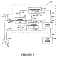
- FIG. 1 illustrates one embodiment of a light emitting diode (LED) control system, indicated by the reference number 100 within a dashed line.
- Control system 100 is electrically connected to an LED 102 using a first LED conductor 104 and a second LED conductor 106.
- LED 102 is operable to produce light, represented by arrows 108, when the LED receives an operating current 110 through the LED conductors in a range of operating currents and receives an operating voltage 112 in a range of operating voltages across the LED conductors.
- control system 100 includes a power supply 114 which is connected to a line power source 116 through line conductors 118.
- the utility power source provides an AC line voltage at a typical line voltage, such as 110 Volts RMS, to power supply 114.
- Power supply 114 converts the utility power to the operating voltage in the range of operating voltages and applies the operating voltage to the LED conductors.
- Power supply 114 also converts the utility power to operating current 110 in the range of operating currents and applies the operating current to the LED conductors.
- a separate transformer (not shown in Figure 1 ) can be used for transforming the line power from the line voltage source to a transformed power.
- the power supply receives the transformed power from the transformer and produces the operating current and operating voltage as discussed.
- Power supply 114 can be controlled by a controller 120 through a control line 122.
- Controller 120 provides a current control signal 124 which controls the amount or magnitude of the operating current applied to the LED conductors.
- the amount of light produced by the LED is directly related to the amount of operating current that the LED receives. Therefore, by controlling the operating current, the controller can control the amount of light produced by the LED.
- Controller 120 can be connected to a current measurement analog to digital (A/D) converter 126 or other current sensor which detects the magnitude of the operating current and produces a current sensed signal 128 that is supplied to the controller through a current sensed signal line 130. Using the current sensed signal, the controller can determine the present level of the operating current and can change current control signal 124 to adjust the magnitude of the operating current.
- the current can be determined by producing the current at a known magnitude.
- a voltage measurement A/D converter 132 or other voltage sensor is connected between the first and second LED conductors using voltage sensor conductors 134 and 136.
- Converter 132 detects the voltage across the LED conductors and produces a voltage sensed signal 138 on a voltage sensed signal line 140.
- the voltage sensed signal line is connected to controller 120, which receives the voltage sensed signal 138 and can determine the operating voltage that is supplied to LED 102. It should be noted that while LED 102 is presently discussed as a single LED, many of the concepts and embodiments are applicable to multiple LED's as well. Specific examples of multiple LED systems will also be discussed below.
- Controller 120 can include a processor 142, a clock 144 and a memory 146 along with software, not specifically shown, which enables the controller to determine the operating current and the operating voltage based on the current sensed signal 128 and the voltage sensed signal 138, respectively.
- the software can be configured to operate the controller as required in view of the overall disclosure. Controller 120 can also store values of the operating current and voltage in the memory along with the times at which the stored values occurred, among other things.
- the LED is operable at an operating temperature which is at a safe level if it remains below a maximum temperature. If the temperature exceeds the maximum temperature then the LED can be subject to thermal damage which can reduce the lifetime of the LED or cause rapid failure of the LED. In some instances, the heat causes an internal resistance of the LED to decrease which, in turn, increases the amount of current that flows through the LED which increases the heat produced. Left unchecked, the LED enters a condition of thermal runaway where the heat caused by the increased current which is caused by the heat eventually causes the temperature of the LED to exceed the maximum temperature and the LED fails.
- control system 100 can determine the temperature of the LED based on electrical measurements through the two LED conductors. This allows the control system to set the operating current to prevent the LED from over heating as well as allowing for the determination of the operating lifetime of the LED, among other things.
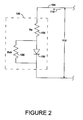
- a diode equivalent circuit 150 is shown connected to first LED conductor 104 and second LED conductor 106.
- LED 102 can be represented by the diode equivalent circuit which includes a diode junction 152, a series resistance 154 and a shunt resistance 156.
- I is the operating current flowing through the LED
- I o is a constant depending on the LED properties
- V is a voltage applied across the diode junction of the LED
- Eg is a value that is closely related to the optical band gap of the semiconductor at the diode junction referred to as the "effective" optical band gap
- A is a constant known as the diode factor which is usually a value between 1 and 2
- k is Boltzmann's constant
- T is the temperature of the semiconductor diode junction in degrees Kelvin.
- the effective shunt resistance is a result of surface and junction imperfections while the series resistance results from sheet resistance of the semiconductor doped layers, contact resistance and the wires.
- the effective shunt resistance is extremely high as the junction depletion width increases. This insulating layer allows for essentially no current flow through the reverse biased LED.
- a Zener diode (not shown) is usually placed across the diode to drain off current at voltages above about 5 volts.
- Equation 1 describes the current, voltage and temperature operation of the LED to an acceptable level of accuracy within a range of operating voltages where the operating voltage is above where the shunt resistance dominates and below where the series resistance dominates. In one embodiment, this range is from about 1.5 V to about 2.5 V, however this range may be larger or smaller depending on characteristics of the LED.
- the effective optical band gap is nearly the same for all white LED's since most LED's use blue light to produce the white light, even when different semiconductor materials are used. In many white LED's, the blue or UV light is used to excite phosphor to produce white light in the white LED's. Applicant has empirically demonstrated with several commercial LED's that the effective optical band gap is 3.2 eV.
- the diode factor A is taken to be 2, which is usually a good assumption for LED's for diodes where junction recombination dominates.
- the effective band gap can also be determined for the LED by solving Equation 1 for Eg if all of the other variables in Equation 1 are known.
- I I o exp V ⁇ IRs ⁇ E g AkT
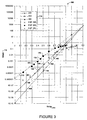
- FIG. 1 A comparison of experimental data with results obtained using Equation 1 is shown in a graph 160 in Figure 3 .
- Graph 160 shows a plot of a log of operating current 110 plotted against operating voltage 112 at three different experimental temperatures; 260 degrees Celsius, 295 degrees Celsius and 383 degrees Celsius (hereinafter C).
- C 260 degrees Celsius, 295 degrees Celsius and 383 degrees Celsius
- a value of 5 x 10 2 Amps was used in Equation 1 for I 0 to make the calculated data fit the experimental data.
- the experimental data was obtained by immersing the LED in a temperature controlled mineral oil bath while the data was taken.
- a thermocouple was welded to a metal slug of the LED to measure the temperature of the LED and oil bath and the operating current and operating voltage were measured.
- the experimental results for the log current vs. voltage points at 260 C are shown by small circular dots, some of which are indicated by the reference number 162, the temperature curve of theoretical results obtained using Equation 1 for the temperature of 260 C are represented by dashed line 164.
- Data points for the experimental results of the current vs. voltage at 295 C are shown as X's, some of which are indicated by the reference number 166.
- Solid line 168 is a temperature curve that shows the theoretical results obtained using Equation 1 with the 295 C temperature.
- the experimental results for current vs. voltage at 383 C are shown by circular dots, some of which are indicated by the reference number 170.
- a temperature curve of the theoretical results obtained using Equation 1 at 383 C are shown by dashed line 172. Key 174 also shows which information is experimental and which was obtained using Equation 1 for subsequently generating the three linear plots.
- the temperature curve moves to the left and the slope of the curve decreases. Therefore by determining a point on the graph of current and voltage of an LED, the temperature of the LED can be determined based on where the point falls on the graph. Also, by determining more than one point based on more than one current and voltage, the slope of the temperature curve can be determined which can then establish the temperature for the multiple points. Further, by using Equation 1, a given current and voltage can be used to determine a single temperature of the LED at a given time.
- Control system 100 can determine the temperature of LED 102 through the two wire connection to the LED using the first and second LED conductors 104 and 106.
- Operating current 110 can be provided by power supply 114 at a known amplitude.
- Operating voltage 112 can be determined by voltage measurement A/D converter 132.
- controller 120 can determine the operating temperature of LED 102 based on current flow and voltage across the LED conductors. This allows the temperature of the LED to be determined from a location that is remote from the LED without the need for additional wires to connect to the LED. This also provides an accurate determination of the actual temperature of the LED die itself, not the temperature of the atmosphere around the LED as provided by a thermal detection device that is located in the thermal pathway of the LED.
- controller 120 controls power supply 114 to produce a pulse 111 of current that is superimposed on operating current 110 through the LED conductors.
- This current pulse can be produced at a known magnitude or the current can be accurately measured with current measurement A/D converter 126.
- Current pulse 111 is shown in the present example as a negative pulse which lowers the operating current while still keeping the operating current positive, but other pulse shapes can also be used.
- the current pulse causes voltage 112 to react with a corresponding voltage pulse 113 which can be measured using the voltage measurement A/D converter 132.
- Voltage pulse 113 is a temporary reduction in operating voltage that still maintains the forward bias across the LED. Controller 120 then uses the amplitudes of the current and voltage pulses to determine the temperature of the LED using Equation 1.
- a voltage pulse can be used in place of the current pulse.
- the voltage pulse would be applied to the LED conductors at an amplitude that is either known or sensed and the resulting current pulse can be measured using the current measurement A/D converter. It should be understood that measurements of current or voltage pulses can be accomplished in a number of different ways in view of the recognitions that have been brought to light herein.
- an average temperature of groups of LEDs that are arranged in series or parallel can be determined based on one or more current pulses through the LEDs.
- the current pulse can be an increase or a decrease in the operating current, and the current pulse can also be in the shape of a ramp, triangle wave or other shape that provides more than one current. In the case where the current pulse includes a shape such as the ramp, the current pulse will provide more than one different current amplitude which, in response, will cause the voltage to exhibit more than one different voltage amplitude. These multiple corresponding currents and voltages can then be used to determine the temperature either based on points on a graph, such as graph 160, or based on a slope of a temperature curve. In one example, the current pulse can be used to put the corresponding sensed voltage in a voltage range, described above, between where the series resistance of the LED and the shunt resistance of the LED dominate.
- pulses can also be used and the pulses can be produced at regular intervals, or based on the temperature determined or on other parameters.
- power supplies can provide anomalies such as ripples in the current which can be used as the current pulse. Switching type power supplies are one example of these types of devices.
- the current pulse can be sufficiently short in duration such that any change in light output by the LED caused by the pulse is not perceivable by humans. This avoids any perceived flickering of the light level that would not be desirable in a lighting system that is used at least partially for illumination for human perception.
- High persistence phosphors can be used so that a longer pulse duration can be used. The longer pulse can improve the accuracy of the temperature determination by allowing for the use of a more accurate A/D converter which uses a longer sampling time and can average out random noises and other interference.
- control system 100 can control the operating current to the LED so that the LED temperature is maintained at a safe operating temperature below which heat damage to the LED can occur.
- Controller 120 can be programmed with the maximum safe operating temperature of the LED and can compare the determined temperature with the safe operating temperature. The controller can raise or lower the operating current until the LED operates at a desired operating temperature. The controller can also provide other control functions.
- the control system can also record the determined temperatures to a file in the memory along with the time of the temperature. In this way, the control system can keep a running tally of the operating temperature of the LED and time of operation of the LED to project the lifetime of the LED.
- the memory can be non-volatile memory so that the system can remember the temperature of the LED in the event of a brief power failure. When power is restored, this allows the control system to resume operation of the LED by setting the operating current based at least partially on the stored operating temperature.
- Operating current and/or operating voltage or other parameters can also be stored into memory for tracking other information regarding the LED. For instance, by tracking operating current, operating voltage and time, the control system can monitor power consumption of the LED. Overall operating time of the LED can be tracked by monitoring the time that operating current and/or operating voltage are applied to the LED.
- a control system 180 includes a connection with a thermistor 182.
- Thermistor 182 is electrically connected to controller 120 with thermistor conductors 184 so that the controller can determine a thermistor temperature at the location of the thermistor by determining a resistance of the thermistor.
- thermistor 182 is located remote from LED 102 but is in the same thermal environment as the LED. By being in the same environment, thermistor 182 and LED 102 are essentially at the same temperature prior to operation of the LED at startup or after the LED has had sufficient time to cool to the ambient temperature after operation. In this way, thermistor 182 can be used to determine a temperature of the LED.
- Thermistor 182 can also be mounted near the LED and/or within the same enclosure as LED 102, such as within a light fixture. In this case, the thermistor conductors would reach from the controller to the location of the thermistor near the LED. Also, this allows the control system to be in a different thermal environment from the LED and thermistor.
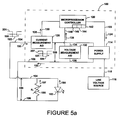
- a thermistor 186 is electrically connected in parallel with LED 102 and is positioned in a thermal pathway to receive heat from the LED.
- Thermistor 186 is chosen to have an effective resistance range that is lower than an effective resistance of the LED when reverse biased. At a reverse bias voltage, up to about -5 Volts, the reverse bias resistance of the LED is extremely high.
- the thermistor can also be chosen to have a forward voltage bias resistance that is much higher than an effective forward voltage resistance of the LED.
- a control system 188 can apply a current pulse 189 to the LED conductors such that a reverse bias voltage pulse 191 is created and a reverse bias voltage 199 is seen across the LED.
- the current pulse 189 causes a reverse drive current 193 in the LED conductors.
- One portion of the reverse drive current flows through the LED as a leakage current 195 which does not cause the LED to produce light.
- Another portion of the reverse drive current flows through the thermistor as a reverse thermistor current 197.
- the leakage current flow through the LED is insignificant compared with the reverse thermistor current flow through the thermistor and therefore the leakage current can be ignored while still gaining a reasonably accurate temperature measurement from the thermistor.
- the temperature of the thermistor is the same as the LED temperature. Connecting the thermistor in parallel with the LED allows the thermistor to be positioned with the LED and away from the control system while maintaining the advantage of only using the two LED conductors for powering the LED and for temperature determination.
- Forward drive current 201 is applied to the LED conductors.
- Forward drive current 201 includes one portion which flows through the LED and is referred to as the forward operating current 203 and another portion that flows through the thermistor which is referred to as a forward thermistor current 205.
- the forward drive current produces a forward operating voltage 207 across the LED.
- the controller By determining an ambient temperature of the LED, applying a current pulse to the LED, determining a magnitude of the current pulse and the resulting magnitude of voltage pulse, the controller has three variables; current, voltage and temperature, that can be used in Equation 1. Using the values determined for these variables, and supplying known or estimated values for other parameters, the controller can solve Equation 1 for any one of the remaining parameters. For instance, knowing the operating current, operating voltage, temperature, I o and the diode factor A, the controller can calculate the effective band gap Eg. By knowing the other variables, the diode factor can be calculated.
- the thermistor temperature can also be used in a calibration procedure to increase the accuracy in later determining the temperature using the operating current and operating voltage.
- the thermistor can be included in the diode package along with the LED die and in some cases a zener diode.
- control system of the several embodiments disclosed can be located remotely from the LED or within the same enclosure as the LED, such as within a light fixture.
- One or more components of the control system can also be arrange on one or more integrated circuits which can be included in a single LED package along with the LED die.
- the control system is located remotely from the LEDs.
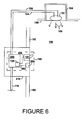
- the control system is included in a switch assembly 190 that is installed at a fixed location in a wall 192.
- Switch assembly 190 includes a switch 191 for controlling the application of power to LED 102 through LED conductors 104 and 106.
- LED 102 can be installed in a lighting fixture 194 that can be mounted in a fixed position in a ceiling 196 within a room 198 with wall 192 and switch assembly 190.
- the switch can be a line voltage switch in which case the line voltage is controlled by the switch before it is passed to the control system.
- the line voltage is connected to a control system 200 using line conductors 118.
- Switch 191 is connected using switch conductors 204 to controller 120 within the control system to control power to the LEDs through the control system.
- Switch assembly 190 can have an on/off function and/or dimming capabilities through control by the controller.
- a display 206 can be included and connected to the controller with a display conductor 202 to indicate the status of the switch and/or the LED to a user.
- the display can be one or more colored indicators or can be a screen type display.
- Switch assembly 190 can be configured to fit within and connect to a conventional single-gang electrical box 210 such as those typically used for mounting a conventional single-pole line voltage switch in a wall.
- Control system 220 includes an interface 222 for transferring data gathered by the control system to a supervisor system 224. Data can be transferred from controller 120 to interface 222 over an interface conductor 223.
- the supervisor system can be a system that is used for building control and/or monitoring and can receive data gathered by multiple control systems controlling multiple LEDs at different locations. Information regarding power usage, temperature, operable lifetime of the LED and other useful information based on time, temperature, current and/or voltage can be transmitted between control system 220 and supervisor system 224.
- Control system 220 and/or supervisor system 224 can include displays for notifying users of the status of the LED.
- the supervisor system can provide control instructions to the control system to cause it to control light output.
- the interface can connect to the supervisor system using a cable 226 such as an Ethernet cable, over the line conductors 118 or can use wireless communications such as a ZigBee TM or other type of wired or wireless communication to a building information system.
- Control system 250 includes a power supply 251 with a transformer 252 that is connected to receive line power from line power source 116 through line power conductors 118. Transformer 252 transforms the line voltage, which is 115 Volts AC in the present case, to 12 Volts AC. Line voltage is typically over 100V AC, for the present embodiment.
- Power supply 251 also includes a current controller 256. The transformer is connected to current controller 256 using a power supply conductor 258 to supply the 12 Volt power to the current controller.
- Power supply 251 is configured to use the 12 Volts AC to supply an operating current and operating voltage to multiple LEDs.
- the current controller is connected to two different LEDs, LED 260 and LED 262.
- LEDs 260 and 262 can be separate LEDs in one fixture, can be separate LEDs in separate fixtures or each LED 260 and 262 can each represent multiple LEDs that are connected together and/or with other LEDs within a similar thermal environment in a series, parallel or series-parallel circuit arrangement.
- LED 260 is connected to current controller 256 using LED conductors 264 and LED 262 is connected to current controller 256 using LED conductors 266.
- Current controller 256 powers LEDs 260 and 262 through the respective LED conductors.
- Control system 250 also includes a temperature monitor 270 that is connected to the current controller using a control line 272.
- Temperature monitor 270 includes a processor as well as current and voltage A/D converters that are not specifically shown in this example. Temperature monitor 270 sends control signals over control line 272 to the current controller to set the operating current to each of the LEDs. Based on the known operating characteristics and limitations of the LEDs, a processor of the temperature monitor can regulate the operating current to the LEDs via controlling the DC current or pulsed DC current. That control may make use of user preferences to maintain constant light output and/or to maintain long life. Temperature monitor 270 can also control the current controller to produce current pulses for measurement purposes over each of the LED conductors.
- a multiplexer 274 is connected to LED conductors 264 and 266 using multiplexer conductor lines 276 and 278, respectively.
- Multiplexer 274 is connected to the temperature monitor using a control line 280 and a signal line 282.
- Temperature monitor 270 controls the multiplexer through the control line to selectively receive signals from one or the other of LED conductors 264 or 266 through multiplexer conductor lines 276 or 278.
- the multiplexer then passes the selected signals to the temperature monitor through signal line 282.
- the temperature monitor determines the current and voltage on the selected LED conductor and calculates the corresponding temperature of the LED connected to the selected LED conductor.
- Temperature monitor 270 can then control the current controller to adjust the operating current of the selected LED based on the temperature. This process can then be repeated for the LED that was not previously selected. In this way, each of the LEDs in the system can be monitored for temperature, current, voltage and power usage so long as they have a separate electrical connection to control system 250.
- Control system 250 can be included in a switch assembly with a switch, as previously discussed, and the switch assembly can be arranged for installation in a wall of a room to control LEDs supplying light to the room.
- Control system 250 can also include an interface for communicating with a supervisory system as previously discussed. Using control system 250 with a supervisory system allows the supervisory system to monitor and/or control multiple LEDs on an individual basis.
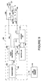
- FIG. 9 Another multiple LED arrangement is shown in Figure 9 wherein a control system 300 is connected to two LEDs 302 and 304 that are electrically connected in series.
- the number of LEDs shown in Figure 9 is exemplary of a system with multiple LEDs.
- the LEDs connect to the control system using LED conductors 310 and 312.
- LEDs 302 and 304 each include an integral heat sink 306 and 308, respectively, that are electrically connected to the LED die.
- the heat sinks are electrically connected to an LED conductor 312 using conductors 314 and 316.
- LED 302 is connected to LED conductor 310 using a first power terminal and an LED conductor 320 connects a second power terminal of LED 302 to a first power terminal of LED 304.
- a second power terminal of LED 304 is connected to an earth ground using a ground conductor 322.
- Control system 300 includes a power supply 330 having a transformer 332 and a power controller 334.
- Transformer 332 receives line power from power source 116 through line power conductors 118 and transforms the line power from a higher voltage to a lower voltage which is transferred to the power controller through a power supply conductor 338.
- Transformer 332 can be electronic or electro-magnetic.
- Control system 300 also includes a temperature monitor 340 which can have a microprocessor controller. Temperature monitor 340 is connected to the power controller using a control line 342 to pass control signals between the temperature monitor and the power controller.
- Power controller 334 supplies power to the LEDs at an operating voltage and at an operating current controlled by the temperature monitor.
- a current A/D converter 344 is connected to the temperature monitor using a control line 346 and a signal line 348.
- each LED effectively has three terminals. Pulses from power controller 334 can be sensed at each LED using current A/D converter 344 through the conductors 314 and 316 as the pulse passes through each LED.
- Control system 300 can also include a control switch and can be arranged to fit within the volume envelope of a typical single-gang junction box.
- Each of the LEDs or groups of LEDs can also include an electronic module with electronics that respond to an analog or digital signal command.
- the signal commands can originate from a controller in a wall switch, or other location.
- Each LED module can respond to such commands individually back to the controller via the conductors 314 or 316 by producing a pulse which the controller can detect through current A/D 344.
- the electronic module can also be arranged to periodically produce a pulse that is unique for each LED or group of LEDs.
- the electronic module can also be configured to divert all or a portion of the current flowing through conductor 310 to the conductors 314 or 316 and on to the current A/D.
- the controller can record the current-voltage characteristics and determine a temperature for the LED connected to the module. The controller can then send a signal to have the module adjust current in the LED as required.
- Each of the LEDs or groups of LEDs can also have a passive or active filter tuned to a different frequency.
- the filter can be used to address the LED individually.
- the pulse can include a frequency component which allows the pulse to be received by a selected individual or group of LEDs to allow the temperature of the selected LED to be determined.
- the control system described herein can be used as a ballast for LED lighting fixtures and much of the control system can be made in a single IC.
- the control system allows the determination of the actual temperature of an LED, not an estimated temperature based on a temperature near the LED.
- the control system can operate using only the two wires normally connected to power the LED. By using centralized control and monitor of the LED temperatures cost for LED fixtures can be reduced over systems in which each fixture includes temperature monitoring and control.
- a method 500 is shown in Figure 10 for determining a temperature of at least one LED.
- Method 500 begins at a start 502 and then proceeds to a step 504 where an operating current and operating voltage are provided to the LED through first and second LED conductors.
- step 504 an operating current and operating voltage are provided to the LED through first and second LED conductors.
- step 506 a current pulse is superimposed on the operating current to the LED through the first and second LED conductors. This results in a voltage pulse that is superimposed on the operating voltage.
- step 508 the voltage pulse is sensed across the first and second LED conductors to determine a magnitude of the voltage pulse.
- Method 500 then proceeds to step 510 where a current magnitude of the current pulse is determined.
- step 512 an operating temperature of the LED is determined based on the current magnitude of the current pulse and the voltage magnitude of the voltage pulse.
- Method 500 then ends at step 514.
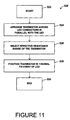
- Method 520 begins at a start step 522 and then proceeds to a step 524 where a thermistor is arranged across the first and second LED conductors in parallel with the LED.
- the thermistor can have an effective resistance range in which at least two different thermistor resistances of the thermistor correspond to at least two different thermistor temperatures of the thermistor.
- the thermistor resistances in the effective resistance range are lower than the reverse bias voltage resistance of the LED and are higher than the forward voltage resistance of the LED.
- step 524 method 520 proceeds to step 526 where the effective resistance range is selected such that, when a forward drive current is applied to the LED conductors, one portion of the forward drive current which flows through the LED is the forward operating current and another portion of the forward drive current which flows through the thermistor is a forward thermistor current which is smaller than the forward operating current.
- step 526 When the reverse bias voltage is supplied to the LED conductors, a reverse drive current flows through the LED conductors in an opposite direction than the forward drive current and one portion of the reverse drive current flows as a leakage current through the LED and which does not cause the LED to produce light and another portion of the reverse drive current flows through the thermistor as a reverse thermistor current which is larger than the leakage current.
- step 528 the thermistor is positioned in a thermal pathway of the LED to receive heat produced by the LED during operation of the LED. The temperature of the thermistor is measurable by determining the thermistor resistance using the reverse thermistor current and the temperature of the thermistor is related to a temperature of the LED.
- step 530 After step 528, method 520 proceeds to step 530 where the method ends.
- a method 550 for electrically communicating with at least one LED assembly to control the LED assembly is shown in Figure 12 .
- Method 550 begins at a start step 552 and then proceeds to a step 554 where a line power source is transformed.
- the line power source having a line voltage greater than 100 Volts AC and the line voltage is converted to a transformed power with a transformed voltage that is less than 50 Volts.
- step 556 proceeds to step 556 where the transformed power is received and an operating power with at least the operating current in the range of operating currents and the operating voltage in the range of operating voltages is created.
- step 556 is a step 558 where the operating current and operating voltage are selectively supplied to the LED assembly through the LED conductors to control light output of the LED assembly.
- step 560 a temperature of the LED is determined through the LED conductors at least partially by determining a magnitude of current through the LED conductors and determining a magnitude of voltage across the LED conductors.
- a control system for determining an actual temperature of a light emitting diode.
- the control system uses conductor that supply power to the light emitting diode to supply a pulse to the light emitting diode.
- the pulse is determined along with a reaction caused by the pulse and the information gained is used in determination of the light emitting diode die temperature which can then be used in controlling current to the light emitting diode to control the temperature of the light emitting diode.
- LEDs are inherently low voltage devices driven by low DC power sources. In general a single white LED will require a forward voltage of approximately 3.5 Volts. In contrast, established power line voltages are AC and of much higher voltage, usually between 110 to 440VAC and 50-60 Hz. Therefore the voltage must usually be reduced, and in most cases transformed to a DC power source. In addition, it is necessary to control the current to an LED because the light output is directly proportional to the current, and excess current can destroy the LED and changes in current will lead to undesirable changes in light output. Unlike incandescent light sources, LEDs require a low constant temperature.
- the maximum operating temperature of white LEDs is approximately 150 Centigrade degrees, and lower temperatures are preferable to preserve the life of the LED and avoid a decrease of the light output that occurs at higher temperatures.
- the decrease in light output is caused by carrier recombination processes at higher temperature and a decrease in the effective optical band gap of the semiconductor.
- J Jo exp qV / nkT ⁇ 1
- V the voltage applied to the LED
- k Boltzmann's constant
- q the electron charge
- Eg the optical bandgap of the semiconductor
- d the doping energy level ibn the semiconductor
- A is a constant related to the physical properties of the semiconductor
- n is known as the diode factor and is a constant usually between 1 and 2.
- thermocouples or thermistors are used to measure the temperature of the LED. These require separate wire connections. Furthermore, the devices must be placed near the LED which is often not convenient. In addition, they do not directly measure the temperature of the LED, but rather some place that is nearby. This method has the advantage of directly measuring the LED and requiring no additional wiring.
- the DC power supply which preferably supplies a constant current, sends a short current pulse to the LED that either briefly raises or lowers the current.
- the power supply using a microprocessor or other calculating device, measures the corresponding change of voltage. Depending on the accuracy required, several current pulses at different levels can be sent out and the corresponding voltages recorded. Using the formulae above, the microprocessor can then calculate or otherwise infer the temperature of the LED.
- the microprocessor can increase or decrease the current to prevent failure and maintain a safe operating condition for the LED or take other actions that may be required.
- the system may need to take a measurement of the LEDs at startup to account for variations of the properties of the LEDs.
- some non volatile memory and a clock may need to run even with the power removed for a brief period so that the system can "remember" the temperature of the LED in the event of a brief power failure.
- this method can work by measuring the LEDs' properties in series if they have a similar thermal environment, or if each LED is wired separately.
- a more complex system may be required.
- One relatively simple method would be to use LEDs that have integral heat sinks that are electrically connected to the LED die. These can be for example grounded together with a "floating" low voltage power supply. In this case each LED effectively has 3 terminals and the pulse can be sensed thru a path to ground as the pulse passes thru each LED.
- An alternate method would be to use an external circuit element that reflect a portion of the pulse at each LED.
- the frequency, magnitude and duration of the pulse(s) used would need to be adjusted so that the change in light output was invisible to the observer. This is easily done at high frequency and short pulse duration where the eye will not perceive the changes caused by the pulses.
Landscapes
- Physics & Mathematics (AREA)
- General Physics & Mathematics (AREA)
- Circuit Arrangement For Electric Light Sources In General (AREA)
- Led Devices (AREA)
Claims (16)
- Verfahren (500) zum Bestimmen einer Temperatur von mindestens einer lichtemittierenden Einrichtung (102) in einer Schaltung, die Folgendes einschließt: eine Leistungsversorgung (114) zum Versorgen der Einrichtung (102) durch erste und zweite Leiter (104, 106) durch Bereitstellen eines Betriebsstroms (110) durch die Leiter (104, 106) und einer Betriebsspannung (112) an die Leiter (104, 106), wo die Einrichtung (102) betriebsfähig ist, Licht (108) zu erzeugen als Antwort auf das Empfangen des Betriebsstroms (110) in einem Bereich von Betriebsströmen und das Empfangen der Betriebsspannung (112) in einem Bereich von Betriebsspannungen, wobei das Verfahren Folgendes umfasst:Bereitstellen (504) des Betriebsstroms (110) und der Betriebsspannung (112) an die Einrichtung (102) durch die ersten und zweiten Leiter (104, 106);Anlegen (506) von mindestens einem Strompuls (111) an die Einrichtung (102) durch die ersten und zweiten Leiter (104, 106), woraus ein Spannungspuls (113) resultiert;Abtasten (508) des Spannungspulses (113) an den ersten und zweiten Leitern (104, 106), der aus dem angelegten Strompuls (111) resultiert, um eine Spannungsgröße des Spannungspulses (113) zu bestimmen;Bestimmen (510) einer Stromgröße des Strompulses (111); undBestimmen (512) einer Betriebstemperatur der lichtemittierenden Einrichtung (102) am bereitgestellten Betriebsstrom (110) auf der Basis der Stromgröße des Strompulses (111) und der Spannungsgröße des Spannungspulses (113),dadurch gekennzeichnet, dass:die Einrichtung (102) eine lichtemittierende Diode, LED, ist; undder mindestens eine Strompuls (111) dem Betriebsstrom (102) an die LED (102) durch die ersten und zweiten Leiter (104, 106) überlagert wird, was zu einem Spannungspuls (113) führt, der der Betriebsspannung (112) überlagert wird.
- Verfahren nach Anspruch 1, außerdem umfassend:vor dem Bereitstellen (504) des Betriebsstroms (110) das Bereitstellen eines anfänglichen Betriebsstroms und einer anfänglichen Betriebsspannung mit einer bekannten anfänglichen Temperatur der LED (102), wobei der anfängliche Strom und die anfängliche Spannung vorzugsweise zu einer Zeit bereitgestellt werden, zu der die LED (102) eine Ruhetemperatur erreicht hat, die im Wesentlichen dieselbe ist wie eine Umgebungstemperatur um die LED (102):Verwenden der gemessenen Werte des anfänglichen Betriebsstroms und der anfänglichen Betriebsspannung und der anfänglichen Temperatur, um mindestens einen LED-Parameter der LED (102) zu bestimmen, und worin das Bestimmen der Betriebstemperatur das anschließende Verwenden des LED-Parameters einschließt.
- Verfahren nach Anspruch 2, worin das Bestimmen der Betriebstemperatur (512) einschließt, dass der LED-Parameter in einer idealen Diodengleichung verwendet wird, worin der LED-Parameter entweder eine effektive Bandlücke der LED betrifft oder dazu verwendet wird, um eine Strom-Spannungs-Kurve (164) für mindestens eine Temperatur zu bestimmen.
- Verfahren nach Anspruch 1, worin der überlagerte Strompuls (111) ein erster Strompuls ist und der Spannungspuls (113) ein erster Spannungspuls ist, und außerdem umfassend:Überlagern von mindestens einem zweiten verschiedenen Strompuls (111) auf den Betriebsstrom (110), was zu einem zweiten verschiedenen Spannungspuls (113) führt, der der Betriebsspannung (112) überlagert wird;Ableiten einer Betriebstemperaturkurve aus einem Logarithmus einer Größe der Strompulse als Funktion einer Größe der Spannungspulse;Bestimmung einer Steigung der Betriebstemperaturkurve; undBestimmen der Betriebstemperatur der LED (102) auf der Basis der bestimmten Steigung der Betriebstemperaturkurve und vorzugsweise auf der Basis eines Vergleichs der Steigung der Betriebstemperaturkurve mit vorgegebenen Steigungswerten, die verschiedenen LED-Temperaturen entsprechen.
- Verfahren nach Anspruch 1, worin das Überlagern das Auswählen einer Leistungsversorgung (114) einschließt, die einen Welligkeitsstrom aufweist, und das Verwenden des Welligkeitsstroms als den Strompuls (111).
- Verfahren nach Anspruch 1, worin die Schaltung, die die LED (102) und die Leistungsversorgung (114) einschließt, Teil einer Einrichtung mindestens zum Bereitstellen von Beleuchtung ist, um die visuelle Wahrnehmung von Menschen zu unterstützen, und wo die Überlagerung des Strompulses (111) auf den Betriebsstrom (110) eine vorübergehende Veränderung im Lichtpegel aus der LED (102) erzeugt und die vorübergehende Veränderung im Lichtpegel kleiner ist als ein Intervall mit einer für Menschen nicht wahrnehmbaren Dauer.
- Verfahren nach Anspruch 1, worin die LED (102) mit einer sicheren Betriebstemperatur betriebsfähig ist, die kleiner ist als eine maximale Temperatur, und mit einer schädlichen Temperatur, die die maximale Temperatur übersteigt, thermischem Schaden ausgesetzt ist, wobei das Verfahren außerdem umfasst:Vergleichen der Betriebstemperatur mit der maximalen Temperatur; undReduzieren des Betriebsstroms (110) als Antwort auf die Betriebstemperatur, die die maximale Temperatur übersteigt.
- Verfahren nach Anspruch 1, worin der überlagerte Strompuls (111) die Größe des Betriebsstroms (110) auf einen Wert reduziert, der kleiner ist als ein anderer Wert des Betriebsstroms (110), der sonst ohne den überlagerten Strompuls (111) vorhanden wäre.
- Verfahren nach Anspruch 1, außerdem umfassend:Anordnen (524) eines Thermistors (182) an die ersten und zweiten Leiter parallel zur LED (102), sodass der Strompuls (111) durch eine parallele Kombination aus der LED (102) und dem Thermistor (182) fließt, und Auswählen des Thermistors (182), sodass er einen effektiven Widerstandsbereich hat, der niedriger ist als ein Rückwärts-Bias-Widerstand der LED (102) und der höher ist als ein Vorwärts-Spannungswiderstand der LED (102); undworin die Überlagerung des Strompulses (111) den Strom (110) zur LED (102) dazu veranlasst, vorübergehend die Richtung umzukehren, um den Bias zur LED (102) umzukehren, und eine relativ größere Menge des Strompulses (111) zu veranlassen, durch den Thermistor (182) zu fließen, und eine relativ kleinere Menge des Strompulses (111) zu veranlassen, durch die LED (102) als ein Leckstrom zu fließen; undBestimmen einer Temperatur des Thermistors (182) auf der Basis eines Teils des Strompulses (111), der durch diesen fließt.
- Verfahren nach Anspruch 9, einschließlich des Verwendens der Thermistor-Temperatur in einer Kalibrierprozedur, um eine Genauigkeit der Bestimmung der Betriebstemperatur der LED (102) zu erhöhen.
- Verfahren nach Anspruch 1, außerdem umfassend:Empfangen mit einem elektrischen Ballast einer Netzleistung von einer Netzleistungsquelle, und zwar die Netzleistung in der Form eines Netzwechselstroms und einer Netzwechselspannung, wobei die Wechselspannung eine RMS(Quadratmittel)-Spannung von über 100 Volt hat und worin das Bereitstellen des Betriebsstroms (110) an die LED (102) das Umwandeln des Netzwechselstroms in den Betriebsstrom unter Verwendung des elektrischen Ballasts einschließt; undKonfigurieren des elektrischen Ballasts auf eine Größe, die kleiner ist als eine Volumen-Hülle einer herkömmlichen Single-Gang-Abzweigdose.
- Verfahren nach Anspruch 1, außerdem umfassend:Bestimmen von mehrfachen Betriebstemperaturen zu mehrfachen verschiedenen Zeiten und Speichern von Werten der Temperaturen und Zeiten, zu denen die Temperaturen zur Verwendung im Bestimmen einer gesamten betriebsfähigen Lebensdauer der LED (102) bestimmt wurden, worin die Bestimmung der gesamten betriebsfähigen Lebensdauer der LED (102) vorzugsweise mindestens teilweise auf den mehrfachen Betriebstemperaturen und den mehrfachen Zeiten der Temperatur basiert.
- Verfahren nach Anspruch 12, außerdem umfassend:Aufzeigen der gesamten betriebsfähigen Lebensdauer der LED (102) an einen Benutzer oder Bereitstellen der bestimmten gesamten betriebsfähigen Lebensdauer der LED (102) an ein System, das Leistungsnutzung überwacht.
- Verfahren nach Anspruch 1, worin es mindestens zwei LEDs (260, 262) in der Schaltung gibt, die beide an die ersten und zweiten Leiter (264, 266) elektrisch angeschlossen sind und worin der überlagerte Strompuls (111) eine Frequenzkomponente mit einer vorgegebenen Frequenz einschließt, wobei das Verfahren außerdem umfasst:Leiten des Strompulses an eine erste der LEDs (260, 262) auf der Basis der Frequenzkomponenten, während der Strompuls an die zweite der LEDs (260, 262) auf der Basis der Frequenzkomponenten blockiert wird und worin die bestimmte Betriebstemperatur die Betriebstemperatur der ersten LED (260, 262) ist.
- Verfahren nach Anspruch 1, worin der überlagerte Strompuls (111) eine Stromrampe mit einer Vielzahl von verschiedenen Stromgrößen ist und der abgetastete Spannungspuls (113) eine Spannungsrampe mit einer Vielzahl von verschiedenen Spannungsgrößen ist, die den Stromgrößen entsprechen, sodass die Betriebstemperatur auf der Basis einer Kurve bestimmt wird, die erzeugt wird, indem ein Logarithmus einer Vielzahl von Strömen als Funktion der entsprechenden Vielzahl von Spannungen geplottet wird.
- Steuersystem zum Bestimmen einer Temperatur von mindestens einer lichtemittierenden Diode (102), LED, wobei das Steuersystem die mindestens eine LED mit ersten und zweiten Leitern (104, 106), eine Leistungsversorgung (114), einen Spannungssensor (132), einen Stromsensor (126) und eine Steuerung (120) umfasst, worin das Steuersystem dazu konfiguriert ist, eines der Verfahren nach den Ansprüchen 1 bis 15 auszuführen.
Applications Claiming Priority (3)
| Application Number | Priority Date | Filing Date | Title |
|---|---|---|---|
| US14440809P | 2009-01-13 | 2009-01-13 | |
| US12/683,393 US8358085B2 (en) | 2009-01-13 | 2010-01-06 | Method and device for remote sensing and control of LED lights |
| PCT/US2010/020819 WO2010083171A2 (en) | 2009-01-13 | 2010-01-12 | Method and device for remote sensing and control of led lights |
Publications (3)
| Publication Number | Publication Date |
|---|---|
| EP2380405A2 EP2380405A2 (de) | 2011-10-26 |
| EP2380405A4 EP2380405A4 (de) | 2014-01-01 |
| EP2380405B1 true EP2380405B1 (de) | 2016-10-12 |
Family
ID=42318568
Family Applications (1)
| Application Number | Title | Priority Date | Filing Date |
|---|---|---|---|
| EP10732010.3A Not-in-force EP2380405B1 (de) | 2009-01-13 | 2010-01-12 | System und verfahren zur fernüberwachung und -steuerung von led-leuchten |
Country Status (5)
| Country | Link |
|---|---|
| US (3) | US8358085B2 (de) |
| EP (1) | EP2380405B1 (de) |
| AU (1) | AU2010204851B2 (de) |
| CA (1) | CA2749472A1 (de) |
| WO (1) | WO2010083171A2 (de) |
Families Citing this family (69)
| Publication number | Priority date | Publication date | Assignee | Title |
|---|---|---|---|---|
| US8111001B2 (en) * | 2007-07-17 | 2012-02-07 | Cree, Inc. | LED with integrated constant current driver |
| TWI355484B (en) * | 2007-12-14 | 2012-01-01 | Ind Tech Res Inst | Apparatus and method for measuring character and c |
| DE102008057347A1 (de) * | 2008-11-14 | 2010-05-20 | Osram Opto Semiconductors Gmbh | Optoelektronische Vorrichtung |
| US8232742B2 (en) | 2008-11-27 | 2012-07-31 | Arkalumen Inc. | Method, apparatus and computer-readable media for controlling lighting devices |
| US8358085B2 (en) | 2009-01-13 | 2013-01-22 | Terralux, Inc. | Method and device for remote sensing and control of LED lights |
| US9326346B2 (en) | 2009-01-13 | 2016-04-26 | Terralux, Inc. | Method and device for remote sensing and control of LED lights |
| JP5807880B2 (ja) * | 2009-05-12 | 2015-11-10 | コーニンクレッカ フィリップス エヌ ヴェKoninklijke Philips N.V. | 照明具の負荷を管理するためのインテリジェント調光器 |
| TW201043098A (en) * | 2009-05-18 | 2010-12-01 | Young Optics Inc | Light-emitting apparatus and control method thereof |
| CN104254178A (zh) * | 2009-11-17 | 2014-12-31 | 特锐拉克斯有限公司 | Led电源的检测和控制 |
| US10089921B2 (en) | 2010-02-04 | 2018-10-02 | Ignis Innovation Inc. | System and methods for extracting correlation curves for an organic light emitting device |
| US9881532B2 (en) | 2010-02-04 | 2018-01-30 | Ignis Innovation Inc. | System and method for extracting correlation curves for an organic light emitting device |
| US20140313111A1 (en) | 2010-02-04 | 2014-10-23 | Ignis Innovation Inc. | System and methods for extracting correlation curves for an organic light emitting device |
| US8564214B2 (en) | 2010-05-11 | 2013-10-22 | Arkalumen Inc. | Circuits for sensing current levels within lighting apparatus |
| US9089024B2 (en) | 2010-05-11 | 2015-07-21 | Arkalumen Inc. | Methods and apparatus for changing a DC supply voltage applied to a lighting circuit |
| US9086435B2 (en) | 2011-05-10 | 2015-07-21 | Arkalumen Inc. | Circuits for sensing current levels within a lighting apparatus incorporating a voltage converter |
| US8340941B2 (en) * | 2010-06-04 | 2012-12-25 | Tyco Electronics Corporation | Temperature measurement system for a light emitting diode (LED) assembly |
| MX346857B (es) | 2010-06-18 | 2017-04-03 | Xicato Inc | Modulo de iluminacion de diodo fotoemisor con diagnostico integrado. |
| US8536788B2 (en) | 2010-08-06 | 2013-09-17 | Osram Sylvania Inc. | Thermal control of solid state light sources by variable series impedance |
| US9596738B2 (en) | 2010-09-16 | 2017-03-14 | Terralux, Inc. | Communication with lighting units over a power bus |
| AU2011301977B2 (en) | 2010-09-16 | 2014-05-22 | Terralux, Inc. | Communication with lighting units over a power bus |
| CA2816707C (en) | 2010-11-10 | 2019-10-29 | Terralux, Inc. | Recessed can downlight retrofit illumination device |
| WO2012077046A2 (en) * | 2010-12-09 | 2012-06-14 | Koninklijke Philips Electronics N.V. | Electroluminescent device with adjustable color point |
| US9192009B2 (en) | 2011-02-14 | 2015-11-17 | Arkalumen Inc. | Lighting apparatus and method for detecting reflected light from local objects |
| WO2012122638A1 (en) | 2011-03-16 | 2012-09-20 | Arkalumen Inc. | Lighting apparatus and methods for controlling lighting apparatus using ambient light levels |
| US8939604B2 (en) | 2011-03-25 | 2015-01-27 | Arkalumen Inc. | Modular LED strip lighting apparatus |
| US8573841B2 (en) * | 2011-04-08 | 2013-11-05 | Advanced Micro Devices, Inc. | On-chip temperature sensor |
| US9060400B2 (en) | 2011-07-12 | 2015-06-16 | Arkalumen Inc. | Control apparatus incorporating a voltage converter for controlling lighting apparatus |
| JP5989115B2 (ja) | 2011-08-08 | 2016-09-07 | クォークスター・エルエルシー | 複数の発光素子を備える照明デバイス |
| US9081125B2 (en) | 2011-08-08 | 2015-07-14 | Quarkstar Llc | Illumination devices including multiple light emitting elements |
| US20140239809A1 (en) * | 2011-08-18 | 2014-08-28 | Lynk Labs, Inc. | Devices and systems having ac led circuits and methods of driving the same |
| US8896231B2 (en) | 2011-12-16 | 2014-11-25 | Terralux, Inc. | Systems and methods of applying bleed circuits in LED lamps |
| US8643285B2 (en) | 2012-01-14 | 2014-02-04 | Yang Pan | Constant temperature light emitting diode lighting system |
| US9293447B2 (en) * | 2012-01-19 | 2016-03-22 | Epistar Corporation | LED thermal protection structures |
| DE102012003162A1 (de) * | 2012-02-19 | 2013-08-22 | Hans-Wolfgang Diesing | Temperaturgeregeltes Treiberkonzept für LED-Lampen |
| US9271373B2 (en) * | 2012-06-08 | 2016-02-23 | Dialight Corporation | Remotely distributed power network for an LED lighting system |
| CN102818651B (zh) * | 2012-07-31 | 2014-07-02 | 广东威创视讯科技股份有限公司 | Led光源温度的检测方法与检测电路 |
| CA2832128A1 (en) * | 2012-11-02 | 2014-05-02 | RAB Lighting Inc. | Dimming for constant current led driver circuit |
| US9265119B2 (en) | 2013-06-17 | 2016-02-16 | Terralux, Inc. | Systems and methods for providing thermal fold-back to LED lights |
| US9591726B2 (en) | 2013-07-02 | 2017-03-07 | Xicato, Inc. | LED-based lighting control network communication |
| US9596737B2 (en) | 2013-07-02 | 2017-03-14 | Xicato, Inc. | Multi-port LED-based lighting communications gateway |
| US10078020B2 (en) * | 2013-08-23 | 2018-09-18 | Whirlpool Corporation | Methods and apparatus to determine home appliance cabinet temperature using a light emitting diode (LED) |
| CN105637982B (zh) * | 2013-09-06 | 2018-04-27 | 飞利浦灯具控股公司 | 用于电力线路编码的控制器和电力线路编码方法 |
| JP2015103666A (ja) * | 2013-11-25 | 2015-06-04 | セイコーエプソン株式会社 | 発光装置および画像表示装置 |
| US9907148B2 (en) | 2014-03-10 | 2018-02-27 | Dynotron, Inc. | LED lighting system having at least one heat sink and a power adjustment module for modifying current flowing through the LEDs |
| US9204524B2 (en) | 2014-03-10 | 2015-12-01 | Dynotron, Inc. | Variable lumen output and color spectrum for LED lighting |
| US10598320B2 (en) * | 2014-07-02 | 2020-03-24 | Ledvance Llc | Integral cooling for LED lighting source |
| US10098199B2 (en) * | 2014-08-13 | 2018-10-09 | Lumenetix, Inc. | Architectures for light emitting diode (LED) lighting systems |
| RU2711242C2 (ru) * | 2015-04-14 | 2020-01-15 | Филипс Лайтинг Холдинг Б.В. | Световая система и способ оценки окончания срока службы по меньшей мере одной ее лампы |
| US10225904B2 (en) | 2015-05-05 | 2019-03-05 | Arkalumen, Inc. | Method and apparatus for controlling a lighting module based on a constant current level from a power source |
| US9992829B2 (en) | 2015-05-05 | 2018-06-05 | Arkalumen Inc. | Control apparatus and system for coupling a lighting module to a constant current DC driver |
| US9775211B2 (en) | 2015-05-05 | 2017-09-26 | Arkalumen Inc. | Circuit and apparatus for controlling a constant current DC driver output |
| US9992836B2 (en) | 2015-05-05 | 2018-06-05 | Arkawmen Inc. | Method, system and apparatus for activating a lighting module using a buffer load module |
| US10568180B2 (en) | 2015-05-05 | 2020-02-18 | Arkalumen Inc. | Method and apparatus for controlling a lighting module having a plurality of LED groups |
| CA2891165A1 (en) | 2015-05-14 | 2016-11-14 | Peter E. Freill | Lighting assembly, system and installation method for hardscapes and steps |
| CN105468332B (zh) * | 2015-11-20 | 2017-11-28 | 中国科学技术大学 | 一种数据处理后置型的即时真随机信号发生器 |
| DE102016202501B4 (de) * | 2016-02-18 | 2022-03-17 | Continental Automotive Gmbh | Verfahren zum Bestimmen eines Kalibrierstrompulses |
| TWI614485B (zh) * | 2016-12-01 | 2018-02-11 | 新唐科技股份有限公司 | 溫度感測裝置及其溫度感測方法 |
| US11191136B2 (en) | 2018-07-16 | 2021-11-30 | Jiaxing Super Lighting Electric Appliance Co., Ltd. | LED lighting system, apparatus, and dimming method |
| US11071178B2 (en) | 2018-07-16 | 2021-07-20 | Jiaxing Super Lighting Electric Appliance Co., Ltd. | LED lighting system, apparatus, and dimming method |
| US12513794B2 (en) | 2018-07-16 | 2025-12-30 | Jiaxing Super Lighting Electric Appliance Co., Ltd. | Light-emitting diode lamp illumination system, and dimmer and light-emitting diode lamp thereof |
| US20210074880A1 (en) * | 2018-12-18 | 2021-03-11 | Bolb Inc. | Light-output-power self-awareness light-emitting device |
| US10796977B2 (en) * | 2019-03-04 | 2020-10-06 | Intel Corporation | Method and apparatus to control temperature of a semiconductor die in a computer system |
| CN114097305B (zh) * | 2019-07-09 | 2025-09-05 | 昕诺飞控股有限公司 | 控制照明装置的方法、照明控制电路和照明系统 |
| CN113692093B (zh) * | 2021-08-23 | 2024-01-26 | 华域视觉科技(上海)有限公司 | 发光模组控制方法、电子设备、发光模组、车灯和车辆 |
| US12523548B2 (en) * | 2022-08-02 | 2026-01-13 | Borgwarner Inc. | Thermistor self-heating compensation |
| TWI849621B (zh) * | 2022-12-14 | 2024-07-21 | 松翰科技股份有限公司 | 熱感測方法 |
| US12089316B1 (en) * | 2023-12-14 | 2024-09-10 | Jiangmen Jinglian Technology Development Co., Ltd. | PLC signal control lamp system with adaptive power supply |
| US12607520B1 (en) * | 2025-05-15 | 2026-04-21 | 2422353 Ontario Limited | Temperature sensor for high-temperature applications |
| CN121194361B (zh) * | 2025-11-27 | 2026-02-27 | 四川鹏天科技发展有限公司 | 一种路灯调光方法及系统 |
Family Cites Families (234)
| Publication number | Priority date | Publication date | Assignee | Title |
|---|---|---|---|---|
| DE2503679C2 (de) * | 1975-01-30 | 1983-01-27 | Robert Bosch Gmbh, 7000 Stuttgart | Fernwirksystem zum selektiven Ansteuern von Verbrauchern, insbesondere in Kraftfahrzeugen |
| JPS57133685U (de) | 1981-02-10 | 1982-08-20 | ||
| NL8200517A (nl) * | 1982-02-11 | 1983-09-01 | Tno | Instelschakeling voor licht-emitterende diode met temperatuurcompensatie. |
| US4633161A (en) | 1984-08-15 | 1986-12-30 | Michael Callahan | Improved inductorless phase control dimmer power stage with semiconductor controlled voltage rise time |
| JPS6166564A (ja) | 1984-09-07 | 1986-04-05 | Hitachi Ltd | 電源装置 |
| US5021731A (en) | 1989-02-21 | 1991-06-04 | Metricor, Inc. | Thermo-optical current sensor and thermo-optical current sensing systems |
| US5151866A (en) | 1990-03-30 | 1992-09-29 | The Dow Chemical Company | High speed power analyzer |
| US5291607A (en) * | 1990-09-05 | 1994-03-01 | Motorola, Inc. | Microprocessor having environmental sensing capability |
| US5198701A (en) | 1990-12-24 | 1993-03-30 | Davies Robert B | Current source with adjustable temperature variation |
| JP2975160B2 (ja) * | 1991-05-27 | 1999-11-10 | 三菱化学株式会社 | 発光スペクトル制御システム |
| WO1993016489A1 (en) * | 1992-02-10 | 1993-08-19 | Sumitomo Electric Industries, Ltd. | Method for measuring semiconductor junction temperature |
| US5546041A (en) | 1993-08-05 | 1996-08-13 | Massachusetts Institute Of Technology | Feedback sensor circuit |
| US5506490A (en) * | 1993-11-09 | 1996-04-09 | Motorola, Inc. | Method and apparatus for determining external power supply type |
| US5539672A (en) | 1993-12-13 | 1996-07-23 | Hobart Corporation | Microprocessor-based temperature control circuit |
| US5485576A (en) * | 1994-01-28 | 1996-01-16 | Fee; Brendan | Chassis fault tolerant system management bus architecture for a networking |
| US20030052658A1 (en) | 1995-01-11 | 2003-03-20 | Baretich David F. | Method and apparatus for electronic power control |
| US5691605A (en) | 1995-03-31 | 1997-11-25 | Philips Electronics North America | Electronic ballast with interface circuitry for multiple dimming inputs |
| US5661645A (en) | 1996-06-27 | 1997-08-26 | Hochstein; Peter A. | Power supply for light emitting diode array |
| CH690217A9 (de) | 1996-07-01 | 2000-07-14 | Beat Larcher | Verfahren und Vorrichtung zur Leistungs- und Datenübermittlung auf gemeinsamen Leitungen. |
| US5781040A (en) | 1996-10-31 | 1998-07-14 | Hewlett-Packard Company | Transformer isolated driver for power transistor using frequency switching as the control signal |
| US5783909A (en) * | 1997-01-10 | 1998-07-21 | Relume Corporation | Maintaining LED luminous intensity |
| EP0992179B1 (de) | 1997-06-16 | 2002-12-11 | Lightech Electronics Industries Ltd. | Elektrisches schaltnetzteil für ein hybrides beleuchtungssystem |
| US5990725A (en) | 1997-06-30 | 1999-11-23 | Maxim Integrated Products, Inc. | Temperature measurement with interleaved bi-level current on a diode and bi-level current source therefor |
| DE19738140A1 (de) | 1997-09-01 | 1999-03-11 | Siemens Ag | Meßanordnung zur Leistungs- und/oder Leistungsfaktormessung an mindestens einer Meßstelle in einem Wechselspannungsnetz |
| US5942860A (en) | 1997-09-16 | 1999-08-24 | Philips Electronics North America Corporation | Electronic ballast for a high intensity discharge lamp with automatic acoustic resonance avoidance |
| DE19754866A1 (de) | 1997-12-10 | 1999-06-17 | Siemens Ag | Universaldimmer und Verfahren zum Dimmen |
| US5925990A (en) * | 1997-12-19 | 1999-07-20 | Energy Savings, Inc. | Microprocessor controlled electronic ballast |
| US6069457A (en) | 1998-01-20 | 2000-05-30 | Lumion University | Method and apparatus for controlling lights and other devices |
| GB2335334B (en) | 1998-03-13 | 2001-03-28 | And Software Ltd | Apparatus for and method of transmitting and receiving data over a low voltage power distribution system |
| US6095661A (en) | 1998-03-19 | 2000-08-01 | Ppt Vision, Inc. | Method and apparatus for an L.E.D. flashlight |
| WO2000017728A2 (en) | 1998-09-22 | 2000-03-30 | U1, Inc. | Computer controlled ac electrical terminations and network |
| US7423750B2 (en) | 2001-11-29 | 2008-09-09 | Applera Corporation | Configurations, systems, and methods for optical scanning with at least one first relative angular motion and at least one second angular motion or at least one linear motion |
| US6153985A (en) | 1999-07-09 | 2000-11-28 | Dialight Corporation | LED driving circuitry with light intensity feedback to control output light intensity of an LED |
| US6351079B1 (en) * | 1999-08-19 | 2002-02-26 | Schott Fibre Optics (Uk) Limited | Lighting control device |
| JP3445540B2 (ja) * | 1999-11-16 | 2003-09-08 | 常盤電業株式会社 | 電源回路 |
| US6762563B2 (en) | 1999-11-19 | 2004-07-13 | Gelcore Llc | Module for powering and monitoring light-emitting diodes |
| US7202613B2 (en) | 2001-05-30 | 2007-04-10 | Color Kinetics Incorporated | Controlled lighting methods and apparatus |
| US6332710B1 (en) | 2000-07-24 | 2001-12-25 | National Semiconductor Corporation | Multi-channel remote diode temperature sensor |
| US6636003B2 (en) * | 2000-09-06 | 2003-10-21 | Spectrum Kinetics | Apparatus and method for adjusting the color temperature of white semiconduct or light emitters |
| US6429598B1 (en) | 2000-11-24 | 2002-08-06 | R. John Haley | Transformer and control units for ac control |
| US6930737B2 (en) | 2001-01-16 | 2005-08-16 | Visteon Global Technologies, Inc. | LED backlighting system |
| US6382812B1 (en) * | 2001-02-13 | 2002-05-07 | Min Hsun Hsu | Decorative light string |
| US7029145B2 (en) * | 2001-03-19 | 2006-04-18 | Integrated Power Components, Inc. | Low voltage decorative light string including power supply |
| EP1271799A1 (de) | 2001-06-28 | 2003-01-02 | "VLAAMSE INSTELLING VOOR TECHNOLOGISCH ONDERZOEK", afgekort "V.I.T.O." | Verfahren und Vorrichtung zur Laststeuerung einer elektrischen Leistungsversorgung |
| US20030015973A1 (en) * | 2001-07-18 | 2003-01-23 | Kevin Ovens | Solid state traffic light with predictive failure analysis |
| US6842668B2 (en) * | 2001-09-06 | 2005-01-11 | Genlyte Thomas Group Llc | Remotely accessible power controller for building lighting |
| EP1313353A1 (de) * | 2001-11-19 | 2003-05-21 | Nokia Corporation | Verfahren und Anordnung zum Betreiben einer Leuchtdiode |
| JP2003188415A (ja) | 2001-12-18 | 2003-07-04 | Asahi Matsushita Electric Works Ltd | Led点灯装置 |
| IL147578A (en) * | 2002-01-10 | 2006-06-11 | Lightech Electronics Ind Ltd | Lamp transformer for use with an electronic dimmer and method for use thereof for reducing acoustic noise |
| US6693394B1 (en) * | 2002-01-25 | 2004-02-17 | Yazaki North America, Inc. | Brightness compensation for LED lighting based on ambient temperature |
| GB0204212D0 (en) * | 2002-02-22 | 2002-04-10 | Oxley Dev Co Ltd | Led drive circuit |
| US7358679B2 (en) * | 2002-05-09 | 2008-04-15 | Philips Solid-State Lighting Solutions, Inc. | Dimmable LED-based MR16 lighting apparatus and methods |
| US6762629B2 (en) * | 2002-07-26 | 2004-07-13 | Intel Corporation | VCC adaptive dynamically variable frequency clock system for high performance low power microprocessors |
| US7507001B2 (en) * | 2002-11-19 | 2009-03-24 | Denovo Lighting, Llc | Retrofit LED lamp for fluorescent fixtures without ballast |
| ES2569057T3 (es) | 2002-12-19 | 2016-05-06 | Koninklijke Philips N.V. | Fuente de alimentación de LEDs |
| JP2004253364A (ja) * | 2003-01-27 | 2004-09-09 | Matsushita Electric Ind Co Ltd | 照明装置 |
| JP3874188B2 (ja) * | 2003-02-13 | 2007-01-31 | ノーリツ鋼機株式会社 | Led光源の温度調節装置 |
| JP4370794B2 (ja) | 2003-03-26 | 2009-11-25 | パナソニック電工株式会社 | Led調光点灯装置及び照明器具 |
| US7049765B1 (en) * | 2003-04-11 | 2006-05-23 | Tremaine Sr John M | Transformer for dimmer switch or on/off switch and method of use |
| JP2003317979A (ja) | 2003-05-20 | 2003-11-07 | Tokiwa Dengyo Kk | 電源回路 |
| US20060237636A1 (en) | 2003-06-23 | 2006-10-26 | Advanced Optical Technologies, Llc | Integrating chamber LED lighting with pulse amplitude modulation to set color and/or intensity of output |
| US7034507B2 (en) * | 2003-07-03 | 2006-04-25 | Micron Technology, Inc. | Temperature sensing device in an integrated circuit |
| JP4687460B2 (ja) * | 2003-07-28 | 2011-05-25 | 日亜化学工業株式会社 | 発光装置、led照明、led発光装置及び発光装置の制御方法 |
| JP2005072218A (ja) * | 2003-08-25 | 2005-03-17 | Tdk Corp | 発光素子の温度管理方法および管理装置、および照明装置 |
| US7635957B2 (en) | 2003-09-04 | 2009-12-22 | Koninklijke Philips Electronics, N.V. | LED temperature-dependent power supply system and method |
| US7777430B2 (en) | 2003-09-12 | 2010-08-17 | Terralux, Inc. | Light emitting diode replacement lamp |
| US7318661B2 (en) | 2003-09-12 | 2008-01-15 | Anthony Catalano | Universal light emitting illumination device and method |
| US20050062481A1 (en) | 2003-09-19 | 2005-03-24 | Thomas Vaughn | Wayside LED signal for railroad and transit applications |
| GB0322823D0 (en) * | 2003-09-30 | 2003-10-29 | Oxley Dev Co Ltd | Method and drive circuit for controlling leds |
| US6982528B2 (en) * | 2003-11-12 | 2006-01-03 | Lutron Electronics Co., Inc. | Thermal protection for lamp ballasts |
| AU2004300444B2 (en) | 2003-12-11 | 2009-06-11 | Signify North America Corporation | Thermal management methods and apparatus for lighting devices |
| US7119498B2 (en) | 2003-12-29 | 2006-10-10 | Texas Instruments Incorporated | Current control device for driving LED devices |
| US7126290B2 (en) | 2004-02-02 | 2006-10-24 | Radiant Power Corp. | Light dimmer for LED and incandescent lamps |
| WO2005081591A1 (en) | 2004-02-20 | 2005-09-01 | Koninklijke Philips Electronics N.V. | Electronic ballast with frequency detection |
| US7233258B1 (en) * | 2004-04-13 | 2007-06-19 | Gelcore Llc | LED matrix current control |
| US7215086B2 (en) | 2004-04-23 | 2007-05-08 | Lighting Science Group Corporation | Electronic light generating element light bulb |
| DE102004026468A1 (de) * | 2004-05-29 | 2005-12-22 | Daimlerchrysler Ag | Datenübertragung auf Stromversorgungsleitungen |
| US7628507B2 (en) | 2004-06-04 | 2009-12-08 | The United States of America as represented by the Secretary of Commerce, the National Institute of Standards and Technology | Radiance output and temperature controlled LED radiance source |
| US7317625B2 (en) | 2004-06-04 | 2008-01-08 | Iwatt Inc. | Parallel current mode control using a direct duty cycle algorithm with low computational requirements to perform power factor correction |
| US7675249B2 (en) * | 2004-07-12 | 2010-03-09 | Sony Corporation | Apparatus and method for driving backlight unit |
| US7132805B2 (en) * | 2004-08-09 | 2006-11-07 | Dialight Corporation | Intelligent drive circuit for a light emitting diode (LED) light engine |
| US7737580B2 (en) | 2004-08-31 | 2010-06-15 | American Power Conversion Corporation | Method and apparatus for providing uninterruptible power |
| JP4771043B2 (ja) * | 2004-09-06 | 2011-09-14 | 日本電気株式会社 | 薄膜半導体素子及びその駆動回路並びにそれらを用いた装置 |
| US7150561B1 (en) | 2004-09-16 | 2006-12-19 | National Semiconductor Corporation | Zero temperature coefficient (TC) current source for diode measurement |
| US7276861B1 (en) * | 2004-09-21 | 2007-10-02 | Exclara, Inc. | System and method for driving LED |
| WO2006033057A1 (en) | 2004-09-23 | 2006-03-30 | Koninklijke Philips Electronics N.V. | Light-emitting device |
| DE102004047682A1 (de) | 2004-09-30 | 2006-04-06 | Patent-Treuhand-Gesellschaft für elektrische Glühlampen mbH | LED-Array |
| EP1808050B1 (de) * | 2004-10-22 | 2022-12-07 | Signify Holding B.V. | Verfahren zur ansteuerung einer auf leds basierenden beleuchtungseinrichtung |
| JP4539492B2 (ja) * | 2004-11-19 | 2010-09-08 | ソニー株式会社 | バックライト装置、バックライト駆動方法及び液晶表示装置 |
| US20070273290A1 (en) | 2004-11-29 | 2007-11-29 | Ian Ashdown | Integrated Modular Light Unit |
| CA2488674A1 (en) | 2004-11-30 | 2006-05-30 | Montgomery Clifford Bondi | Multiple dimmer lighting system |
| US7456620B2 (en) | 2004-12-03 | 2008-11-25 | The Regents Of The University Of Colorado | Determining dead times in switched-mode DC-DC converters |
| US7336041B2 (en) * | 2004-12-06 | 2008-02-26 | Vicente Aldape Ayala | Automatic light dimmer for electronic and magnetic ballasts (fluorescent or HID) |
| US7429129B2 (en) | 2005-02-28 | 2008-09-30 | Standard Microsystems Corporation | Proportional settling time adjustment for diode voltage and temperature measurements dependent on forced level current |
| EP1701589B1 (de) | 2005-03-08 | 2008-08-27 | Sony Ericsson Mobile Communications AB | Schaltung und Verfahren zum Überwachen der Temperatur einer Leuchtdiode |
| JP4550638B2 (ja) * | 2005-03-22 | 2010-09-22 | シャープ株式会社 | 面照明装置及びそれを備えた液晶表示装置 |
| US20060214876A1 (en) | 2005-03-23 | 2006-09-28 | Sony Ericsson Mobile Communications Ab | Electronic device having a light bus for controlling light emitting elements |
| US20060238169A1 (en) | 2005-04-22 | 2006-10-26 | William Baker | Temperature controlled current regulator |
| US8459852B2 (en) | 2007-10-05 | 2013-06-11 | Dental Equipment, Llc | LED-based dental exam lamp |
| US7242150B2 (en) * | 2005-05-12 | 2007-07-10 | Lutron Electronics Co., Inc. | Dimmer having a power supply monitoring circuit |
| US7204638B2 (en) * | 2005-05-23 | 2007-04-17 | Etron Technology, Inc. | Precise temperature sensor with smart programmable calibration |
| WO2006133272A2 (en) | 2005-06-06 | 2006-12-14 | Color Kinetics Incorporated | Methods and apparatus for implementing power cycle control of lighting devices based on network protocols |
| BRPI0613294A2 (pt) * | 2005-06-30 | 2012-12-04 | Lutron Electronics Co | dispositivo de controle de carga bifásico de energia liberada a uma carga elétrica a partir de uma fonte de voltagem e fonte de energia para o dispositivo e método para gerar uma voltagem dc (vcc) no referido dispositivo e prover voltagem dc ao controlador do dispositivo de controle de carga |
| KR100651031B1 (ko) | 2005-07-08 | 2006-11-29 | 장민준 | 온도 조절 수단을 구비한 적분구 |
| US7336434B2 (en) * | 2005-07-18 | 2008-02-26 | Hitachi Global Storage Technologies Netherlands B.V. | Predictive failure analysis of thermal flying height control system and method |
| JP4857633B2 (ja) * | 2005-07-20 | 2012-01-18 | スタンレー電気株式会社 | Led光源 |
| US7492108B2 (en) * | 2005-08-11 | 2009-02-17 | Texas Instruments Incorporated | System and method for driving light-emitting diodes (LEDs) |
| CN101292574B (zh) | 2005-08-17 | 2012-12-26 | 皇家飞利浦电子股份有限公司 | 数字控制的照明器系统 |
| KR100735460B1 (ko) * | 2005-09-09 | 2007-07-03 | 삼성전기주식회사 | 온도 보상 기능을 갖는 led 구동 제어 회로 |
| US7986112B2 (en) * | 2005-09-15 | 2011-07-26 | Mag Instrument, Inc. | Thermally self-stabilizing LED module |
| CN2861732Y (zh) | 2005-09-26 | 2007-01-24 | 黄重荣 | 多功能灯具 |
| US7245089B2 (en) * | 2005-11-03 | 2007-07-17 | System General Corporation | Switching LED driver |
| US7245090B2 (en) * | 2005-11-08 | 2007-07-17 | System General Corporation | Switching LED driver with temperature compensation to program LED current |
| CN2924996Y (zh) | 2005-11-13 | 2007-07-18 | 曾祥云 | 一种低成本高性能led照明电路 |
| US7286123B2 (en) | 2005-12-13 | 2007-10-23 | System General Corp. | LED driver circuit having temperature compensation |
| TWI279659B (en) | 2005-12-27 | 2007-04-21 | Polytronics Technology Corp | LED with temperature control function |
| US7755513B2 (en) * | 2006-01-13 | 2010-07-13 | Bwt Property, Inc. | Visual navigational aids based on high intensity LEDS |
| JP2007258227A (ja) | 2006-03-20 | 2007-10-04 | Stanley Electric Co Ltd | Led駆動回路 |
| US20080018261A1 (en) * | 2006-05-01 | 2008-01-24 | Kastner Mark A | LED power supply with options for dimming |
| DE102006029438B4 (de) * | 2006-06-20 | 2018-05-17 | Arnold & Richter Cine Technik Gmbh & Co. Betriebs Kg | Verfahren und Vorrichtung zur Ansteuerung von Leuchtdioden einer Beleuchtungsvorrichtung |
| EP1874097B1 (de) | 2006-06-28 | 2010-06-16 | Osram Gesellschaft mit Beschränkter Haftung | LED-Schaltung mit Stromregelung |
| US7605550B2 (en) | 2006-07-17 | 2009-10-20 | Microsemi Corp.—Analog Mixed Signal Group Ltd. | Controlled bleeder for power supply |
| KR100767385B1 (ko) * | 2006-08-11 | 2007-10-17 | 주식회사 엠앤씨라이팅 | 조명 구동장치 및 그 회로 |
| US20080062070A1 (en) * | 2006-09-13 | 2008-03-13 | Honeywell International Inc. | Led brightness compensation system and method |
| KR20090082378A (ko) * | 2006-10-05 | 2009-07-30 | 코닌클리즈케 필립스 일렉트로닉스 엔.브이. | 광 모듈 패키지 |
| KR100968451B1 (ko) * | 2006-10-16 | 2010-07-07 | 삼성전자주식회사 | 디스플레이장치 및 그 제어방법 |
| TWI345429B (en) * | 2006-11-13 | 2011-07-11 | Polytronics Technology Corp | Light emitting diode apparatus |
| BRPI0720017A2 (pt) | 2006-12-11 | 2017-01-10 | Tir Technology Lp | método e sistema para controlar um ou mais elementos de emissão de luz operados por correntes diretas para gerar uma luz misturada. |
| WO2008070981A1 (en) | 2006-12-12 | 2008-06-19 | Tir Technology Lp | System and method for controlling lighting |
| JP5230182B2 (ja) | 2006-12-13 | 2013-07-10 | キヤノン株式会社 | スイッチング電源装置 |
| US7633037B2 (en) * | 2006-12-19 | 2009-12-15 | Eveready Battery Co., Inc. | Positive temperature coefficient light emitting diode light |
| DE102006061357B4 (de) | 2006-12-22 | 2017-09-14 | Infineon Technologies Austria Ag | Verfahren zur Ansteuerung einer Leuchtstofflampe |
| KR20080058859A (ko) * | 2006-12-22 | 2008-06-26 | 삼성전자주식회사 | 디스플레이장치 및 그 색온도 조절방법 |
| US7556423B2 (en) * | 2007-01-08 | 2009-07-07 | Microchip Technology Incorporated | Temperature sensor bow compensation |
| US20080180414A1 (en) | 2007-01-30 | 2008-07-31 | Kai Ming Fung | Method and apparatus for controlling light emitting diode |
| WO2008096249A2 (en) | 2007-02-07 | 2008-08-14 | Melexis Nv | Led driver |
| US20080238340A1 (en) | 2007-03-26 | 2008-10-02 | Shun Kei Mars Leung | Method and apparatus for setting operating current of light emitting semiconductor element |
| US20080198613A1 (en) | 2007-02-15 | 2008-08-21 | William Cruickshank | LED driver touch switch circuit |
| US7652459B2 (en) | 2007-02-23 | 2010-01-26 | Intel Corporation | Adaptive controller with mode tracking and parametric estimation for digital power converters |
| US7667408B2 (en) | 2007-03-12 | 2010-02-23 | Cirrus Logic, Inc. | Lighting system with lighting dimmer output mapping |
| JP2008224136A (ja) | 2007-03-13 | 2008-09-25 | Matsushita Electric Ind Co Ltd | ファンフィルタユニットの制御装置 |
| US7504783B2 (en) * | 2007-03-23 | 2009-03-17 | National Semiconductor Corporation | Circuit for driving and monitoring an LED |
| US7948190B2 (en) * | 2007-04-10 | 2011-05-24 | Nexxus Lighting, Inc. | Apparatus and methods for the thermal regulation of light emitting diodes in signage |
| DE102008018931A1 (de) | 2007-04-17 | 2008-11-13 | Gyrus ACMI, Inc., Southborough | Lichtquellenleistung auf der Grundlage einer vorbestimmten erfaßten Bedingung |
| US7714517B2 (en) | 2007-04-19 | 2010-05-11 | Au Optronics Corporation | LED driver with current sink control and applications of the same |
| US7663326B2 (en) | 2007-05-22 | 2010-02-16 | Msilica Incorporated | Temperature dependant LED current controller |
| US8112243B2 (en) | 2007-06-20 | 2012-02-07 | The United States Of America As Represented By The Administrator Of The National Aeronautics And Space Administration | Forward voltage short-pulse technique for measuring high power laser array junction temperture |
| US7948398B2 (en) * | 2007-07-05 | 2011-05-24 | Siemens Industry, Inc. | LED traffic signal without power supply or control unit in signal head |
| US8400061B2 (en) * | 2007-07-17 | 2013-03-19 | I/O Controls Corporation | Control network for LED-based lighting system in a transit vehicle |
| GB2451467B (en) | 2007-07-28 | 2013-01-16 | Zetex Semiconductors Plc | Current driving method and circuit |
| TW200905123A (en) * | 2007-07-30 | 2009-02-01 | Topco Technologies Corp | Light emitting diode lamp and illumination system |
| US20090033612A1 (en) | 2007-07-31 | 2009-02-05 | Roberts John K | Correction of temperature induced color drift in solid state lighting displays |
| JP2009083590A (ja) | 2007-09-28 | 2009-04-23 | Toyoda Gosei Co Ltd | 車載用のled照明装置 |
| CN101408297B (zh) * | 2007-10-12 | 2010-06-02 | 富准精密工业(深圳)有限公司 | 可远程监控的发光二极管灯具及其远程监控方法 |
| US7486030B1 (en) | 2007-10-18 | 2009-02-03 | Pwi, Inc. | Universal input voltage device |
| US7812551B2 (en) | 2007-10-19 | 2010-10-12 | American Sterilizer Company | Lighting control method having a light output ramping function |
| WO2009055821A1 (en) | 2007-10-26 | 2009-04-30 | Lighting Science Group Corporation | High efficiency light source with integrated ballast |
| TWI345067B (en) * | 2007-11-23 | 2011-07-11 | Ind Tech Res Inst | Devices and methods for led life test |
| KR101385117B1 (ko) * | 2007-12-06 | 2014-04-15 | 삼성디스플레이 주식회사 | 백라이트 어셈블리, 이를 갖는 표시장치 및 이의 구동에적용되는 전류제어소자의 셧다운 방지방법 |
| WO2009076062A2 (en) * | 2007-12-12 | 2009-06-18 | Honeywell International Inc. | Variable nozzle for a turbocharger, having nozzle ring located by radial members |
| TWI355484B (en) * | 2007-12-14 | 2012-01-01 | Ind Tech Res Inst | Apparatus and method for measuring character and c |
| WO2009079944A1 (en) | 2007-12-18 | 2009-07-02 | Shine Glory Enterprise Limited | Adaptive fluorescent lamp driver circuit |
| EP2073607A1 (de) | 2007-12-19 | 2009-06-24 | Data Display GmbH | LED-Steuerung zur Optimierung der LED-Lebensdauer |
| JP2009152469A (ja) | 2007-12-21 | 2009-07-09 | Fujitsu Ltd | 光源駆動装置および光源駆動方法 |
| US7791326B2 (en) * | 2007-12-28 | 2010-09-07 | Texas Instruments Incorporated | AC-powered, microprocessor-based, dimming LED power supply |
| US8400391B2 (en) * | 2008-01-10 | 2013-03-19 | Honeywell International Inc. | Method and system for improving dimming performance in a field sequential color display device |
| US8072346B2 (en) * | 2008-01-11 | 2011-12-06 | Global Traffic Technologies, Llc | LED light bar for optical traffic control systems |
| US20090179574A1 (en) * | 2008-01-16 | 2009-07-16 | Hsiu-Hui Chang | Backlight module of light emitting diode |
| US8534914B2 (en) * | 2008-01-28 | 2013-09-17 | Nxp B.V. | System and method for estimating the junction temperature of a light emitting diode |
| US8502454B2 (en) * | 2008-02-08 | 2013-08-06 | Innosys, Inc | Solid state semiconductor LED replacement for fluorescent lamps |
| JP4525767B2 (ja) * | 2008-02-14 | 2010-08-18 | ソニー株式会社 | 照明装置及び表示装置 |
| CA2715916A1 (en) | 2008-02-22 | 2009-08-27 | David W. Baarman | Inductive power supply system with battery type detection |
| US7800316B2 (en) | 2008-03-17 | 2010-09-21 | Micrel, Inc. | Stacked LED controllers |
| US8212494B2 (en) | 2008-04-04 | 2012-07-03 | Lemnis Lighting Patents Holding B.V. | Dimmer triggering circuit, dimmer system and dimmable device |
| US8543249B2 (en) | 2008-04-14 | 2013-09-24 | Digital Lumens Incorporated | Power management unit with modular sensor bus |
| US8754589B2 (en) * | 2008-04-14 | 2014-06-17 | Digtial Lumens Incorporated | Power management unit with temperature protection |
| DE102008018808A1 (de) * | 2008-04-15 | 2009-10-22 | Ledon Lighting Jennersdorf Gmbh | Mikrocontroller optimierte Pulsweitenmodulation-(PWM)-Ansteuerung einer Licht emittierenden Diode(LED) |
| US20090267523A1 (en) | 2008-04-24 | 2009-10-29 | Articulated Technologies, Llc | Driver circuit for light sheet module with direct connection to power source |
| US7888688B2 (en) * | 2008-04-29 | 2011-02-15 | Bridgelux, Inc. | Thermal management for LED |
| US7612506B1 (en) | 2008-05-08 | 2009-11-03 | National Central University | Method for controlling light-emission of a light-emitting diode light source |
| EP2283404A4 (de) * | 2008-05-09 | 2014-09-03 | Segan Llc | Adressierbarer led-lichtstrang |
| JP2009282187A (ja) | 2008-05-21 | 2009-12-03 | Renesas Technology Corp | 液晶駆動装置 |
| TW200951415A (en) | 2008-06-06 | 2009-12-16 | Univ Nat Central | Method for measuring junction temperature of light emitting diode (LED) |
| US9001161B2 (en) * | 2008-06-06 | 2015-04-07 | Dolby Laboratories Licensing Corporation | Chromaticity control for solid-state illumination sources |
| US8076870B2 (en) | 2008-06-10 | 2011-12-13 | Alliance Optotek Co., Ltd. | LED illumination system with multiple independent loops |
| US20100007588A1 (en) * | 2008-07-09 | 2010-01-14 | Adaptive Micro Systems Llc | System and method for led degradation and temperature compensation |
| US8258716B2 (en) * | 2008-08-06 | 2012-09-04 | Jui Chih Yen | Driving power supply system of an active type LED with multiple channels |
| TW201012302A (en) * | 2008-09-12 | 2010-03-16 | Univ Nat Central | Control method for maintaining the luminous intensity of a light-emitting diode light source |
| US7994725B2 (en) | 2008-11-06 | 2011-08-09 | Osram Sylvania Inc. | Floating switch controlling LED array segment |
| CA2957199C (en) | 2008-11-26 | 2019-01-08 | Wireless Environment, Llc | Wireless lighting devices and applications |
| US7999491B2 (en) * | 2008-12-02 | 2011-08-16 | Ememory Technology Inc. | LED lighting control integrated circuit having embedded programmable nonvolatile memory |
| US7990077B2 (en) | 2008-12-12 | 2011-08-02 | Cheng Uei Precision Industry Co., Ltd. | LED control circuit |
| JP5342867B2 (ja) * | 2008-12-19 | 2013-11-13 | スタンレー電気株式会社 | 半導体発光装置及び駆動方法 |
| US8358085B2 (en) | 2009-01-13 | 2013-01-22 | Terralux, Inc. | Method and device for remote sensing and control of LED lights |
| DE102009003632B4 (de) | 2009-03-17 | 2013-05-16 | Lear Corporation Gmbh | Verfahren und Schaltungsanordnung zur Ansteuerung einer Last |
| US8575865B2 (en) | 2009-03-24 | 2013-11-05 | Apple Inc. | Temperature based white point control in backlights |
| US8174197B2 (en) | 2009-04-09 | 2012-05-08 | Ge Lighting Solutions Llc | Power control circuit and method |
| TWI468614B (zh) | 2009-04-21 | 2015-01-11 | Cheng Hsi Miao | 可調色溫的燈具 |
| US20100277077A1 (en) | 2009-05-04 | 2010-11-04 | Man Hay Pong | Apparatus and method to enhance the life of Light Emitting diode (LED) devices in an LED matrix |
| US8058810B2 (en) | 2009-05-07 | 2011-11-15 | Linear Technology Corporation | Method and system for high efficiency, fast transient multi-channel LED driver |
| US8791655B2 (en) | 2009-05-09 | 2014-07-29 | Innosys, Inc. | LED lamp with remote control |
| TWI495393B (zh) | 2009-05-09 | 2015-08-01 | Innosys Inc | 通用型調光器 |
| CN101896023A (zh) | 2009-05-20 | 2010-11-24 | 扬光绿能股份有限公司 | 照明装置及其控制方法 |
| US8217591B2 (en) | 2009-05-28 | 2012-07-10 | Cree, Inc. | Power source sensing dimming circuits and methods of operating same |
| EP2257124B1 (de) | 2009-05-29 | 2018-01-24 | Silergy Corp. | Schaltung zur Ankopplung einer Niedrigstromlichtschaltung an einem Dimmer |
| CN101929622A (zh) | 2009-06-19 | 2010-12-29 | 鸿富锦精密工业(深圳)有限公司 | Led照明系统及其控制方法 |
| EP2273851A3 (de) | 2009-06-24 | 2011-05-11 | Nxp B.V. | System und Verfahren zur Steuerung eines LED-Clusters |
| US8192060B2 (en) * | 2009-07-23 | 2012-06-05 | Dean Andrew Wilkinson | Aircraft navigation light |
| US8358081B2 (en) * | 2009-08-21 | 2013-01-22 | Teledyne Technologies Incorporated | Lamp assembly |
| US8283876B2 (en) * | 2009-09-17 | 2012-10-09 | Dialog Semiconductor Gmbh | Circuit for driving an infrared transmitter LED with temperature compensation |
| TWI403215B (zh) * | 2009-10-01 | 2013-07-21 | Upec Electronics Corp | Color Modulation System and Its Modulation Method |
| US8492988B2 (en) | 2009-10-07 | 2013-07-23 | Lutron Electronics Co., Inc. | Configurable load control device for light-emitting diode light sources |
| EP2494852A1 (de) | 2009-10-30 | 2012-09-05 | Koninklijke Philips Electronics N.V. | Selektiv aktivierte zünd-/ableitschaltung für festkörperbeleuchtungssystem |
| US8344659B2 (en) | 2009-11-06 | 2013-01-01 | Neofocal Systems, Inc. | System and method for lighting power and control system |
| TWI501697B (zh) * | 2009-11-12 | 2015-09-21 | Green Solution Tech Co Ltd | 發光二極體電流控制電路、均流器及驅動裝置 |
| CN104254178A (zh) | 2009-11-17 | 2014-12-31 | 特锐拉克斯有限公司 | Led电源的检测和控制 |
| MX2012005844A (es) | 2009-11-20 | 2012-09-28 | Lutron Electronics Co | Circuito de carga controlable para su uso con un dispositivo de control de carga. |
| EP2336741B1 (de) * | 2009-12-18 | 2016-09-07 | Nxp B.V. | Selbstkalibrierungsschaltkreis und Verfahren zur Verbindungstemperaturschätzung |
| US8286886B2 (en) * | 2009-12-23 | 2012-10-16 | Hynix Semiconductor Inc. | LED package and RFID system including the same |
| US8193741B2 (en) * | 2009-12-24 | 2012-06-05 | Nxp B.V. | Boosting driver circuit for light-emitting diodes |
| TWI427598B (zh) * | 2009-12-29 | 2014-02-21 | Au Optronics Corp | 背光模組以及設定其驅動電流之方法 |
| TWI384171B (zh) * | 2010-01-05 | 2013-02-01 | Richtek Technology Corp | 發光二極體的熱折返控制電路及方法 |
| US8299718B2 (en) | 2010-02-17 | 2012-10-30 | Brian Cottrell | Constant temperature LED driver circuit |
| JP5759491B2 (ja) | 2010-03-18 | 2015-08-05 | コーニンクレッカ フィリップス エヌ ヴェ | 半導体式照明器具の調光範囲を広げる方法及び装置 |
| TW201141303A (en) | 2010-05-07 | 2011-11-16 | Light Engine Ltd | Triac dimmable power supply unit for LED |
| JP5785611B2 (ja) | 2010-05-17 | 2015-09-30 | コーニンクレッカ フィリップス エヌ ヴェ | 不適当な調光器動作を検出し修正するための方法及び装置 |
| BR112013000678A2 (pt) | 2010-07-13 | 2016-05-31 | Koninkl Philips Electronics Nv | "circuito de purga, sistema para o controle da potência enviada a uma fonte luminosa, método para eliminar a tremulação da saida de luz por um modo diodo emissor de luz" |
| AU2011301977B2 (en) | 2010-09-16 | 2014-05-22 | Terralux, Inc. | Communication with lighting units over a power bus |
| US8159153B2 (en) | 2010-10-01 | 2012-04-17 | Bridgelux, Inc. | LED light sources with improved thermal compensation |
| US8476847B2 (en) | 2011-04-22 | 2013-07-02 | Crs Electronics | Thermal foldback system |
| WO2012162601A1 (en) | 2011-05-26 | 2012-11-29 | Terralux, Inc. | In-circuit temperature measurement of light-emitting diodes |
| US8872417B2 (en) | 2011-06-22 | 2014-10-28 | Gt Biomescilt Light Limited | Socket adaptor having AC-DC convertor for LED lamp |
| US8896231B2 (en) | 2011-12-16 | 2014-11-25 | Terralux, Inc. | Systems and methods of applying bleed circuits in LED lamps |
| US9265119B2 (en) | 2013-06-17 | 2016-02-16 | Terralux, Inc. | Systems and methods for providing thermal fold-back to LED lights |
-
2010
- 2010-01-06 US US12/683,393 patent/US8358085B2/en active Active
- 2010-01-12 CA CA2749472A patent/CA2749472A1/en not_active Abandoned
- 2010-01-12 AU AU2010204851A patent/AU2010204851B2/en active Active
- 2010-01-12 EP EP10732010.3A patent/EP2380405B1/de not_active Not-in-force
- 2010-01-12 WO PCT/US2010/020819 patent/WO2010083171A2/en not_active Ceased
-
2012
- 2012-12-18 US US13/718,366 patent/US8686666B2/en active Active
-
2014
- 2014-02-11 US US14/177,673 patent/US9161415B2/en active Active
Also Published As
| Publication number | Publication date |
|---|---|
| CA2749472A1 (en) | 2010-07-22 |
| WO2010083171A2 (en) | 2010-07-22 |
| WO2010083171A3 (en) | 2010-10-14 |
| EP2380405A4 (de) | 2014-01-01 |
| AU2010204851B2 (en) | 2013-10-24 |
| US20140217896A1 (en) | 2014-08-07 |
| AU2010204851A1 (en) | 2011-07-28 |
| US20130182744A1 (en) | 2013-07-18 |
| US8686666B2 (en) | 2014-04-01 |
| US9161415B2 (en) | 2015-10-13 |
| US20100176746A1 (en) | 2010-07-15 |
| EP2380405A2 (de) | 2011-10-26 |
| US8358085B2 (en) | 2013-01-22 |
Similar Documents
| Publication | Publication Date | Title |
|---|---|---|
| AU2010204851B2 (en) | Method and device for remote sensing and control of LED lights | |
| US9326346B2 (en) | Method and device for remote sensing and control of LED lights | |
| EP2417838B1 (de) | Dimmbare stromversorgung | |
| KR102006007B1 (ko) | Led 구동 장치 및 이를 이용한 led 구동 방법 | |
| CN102948262B (zh) | 基于led的照明模块的板上诊断 | |
| EP2477459B1 (de) | Hybrides Steuerungssystem | |
| EP2706820B1 (de) | Ansteuerungsvorrichtung für lichtemittierendes Festkörperelement, Beleuchtungsvorrichtung und Beleuchtungskörper | |
| EP2768281B1 (de) | Beleuchtungsvorrichtung und Leuchte | |
| EP3624565A1 (de) | Vorrichtung und verfahren zur steuerung der thermischen gegenkopplung einer leuchtdiode | |
| US20110175532A1 (en) | System and method for supplying constant power to luminuous loads | |
| EP3005839A1 (de) | Systeme und verfahren zur bereitstellung einer selbsteinstellenden lichtquelle | |
| EP2768280A1 (de) | Beleuchtungsvorrichtung und Beleuchtungsarmatur | |
| KR101743064B1 (ko) | 엘이디 조명의 디밍 제어장치 | |
| CN101592702B (zh) | 发光二极管的警示系统 | |
| JP7296894B2 (ja) | 照明ドライバ、照明回路、及び駆動方法 | |
| US10104734B2 (en) | Lighting system | |
| JP2023522734A (ja) | 照明器具のための光源ドライバ | |
| TWI378250B (en) | Light emitting diode alarm system |
Legal Events
| Date | Code | Title | Description |
|---|---|---|---|
| PUAI | Public reference made under article 153(3) epc to a published international application that has entered the european phase |
Free format text: ORIGINAL CODE: 0009012 |
|
| 17P | Request for examination filed |
Effective date: 20110720 |
|
| AK | Designated contracting states |
Kind code of ref document: A2 Designated state(s): AT BE BG CH CY CZ DE DK EE ES FI FR GB GR HR HU IE IS IT LI LT LU LV MC MK MT NL NO PL PT RO SE SI SK SM TR |
|
| DAX | Request for extension of the european patent (deleted) | ||
| A4 | Supplementary search report drawn up and despatched |
Effective date: 20131129 |
|
| RIC1 | Information provided on ipc code assigned before grant |
Ipc: H05B 37/02 20060101AFI20131125BHEP |
|
| 17Q | First examination report despatched |
Effective date: 20160203 |
|
| GRAP | Despatch of communication of intention to grant a patent |
Free format text: ORIGINAL CODE: EPIDOSNIGR1 |
|
| INTG | Intention to grant announced |
Effective date: 20160414 |
|
| GRAS | Grant fee paid |
Free format text: ORIGINAL CODE: EPIDOSNIGR3 |
|
| GRAA | (expected) grant |
Free format text: ORIGINAL CODE: 0009210 |
|
| AK | Designated contracting states |
Kind code of ref document: B1 Designated state(s): AT BE BG CH CY CZ DE DK EE ES FI FR GB GR HR HU IE IS IT LI LT LU LV MC MK MT NL NO PL PT RO SE SI SK SM TR |
|
| REG | Reference to a national code |
Ref country code: GB Ref legal event code: FG4D |
|
| REG | Reference to a national code |
Ref country code: CH Ref legal event code: EP |
|
| REG | Reference to a national code |
Ref country code: AT Ref legal event code: REF Ref document number: 837489 Country of ref document: AT Kind code of ref document: T Effective date: 20161015 |
|
| REG | Reference to a national code |
Ref country code: IE Ref legal event code: FG4D |
|
| REG | Reference to a national code |
Ref country code: DE Ref legal event code: R096 Ref document number: 602010037135 Country of ref document: DE |
|
| REG | Reference to a national code |
Ref country code: FR Ref legal event code: PLFP Year of fee payment: 8 |
|
| REG | Reference to a national code |
Ref country code: LT Ref legal event code: MG4D |
|
| REG | Reference to a national code |
Ref country code: NL Ref legal event code: MP Effective date: 20161012 |
|
| PG25 | Lapsed in a contracting state [announced via postgrant information from national office to epo] |
Ref country code: LV Free format text: LAPSE BECAUSE OF FAILURE TO SUBMIT A TRANSLATION OF THE DESCRIPTION OR TO PAY THE FEE WITHIN THE PRESCRIBED TIME-LIMIT Effective date: 20161012 |
|
| REG | Reference to a national code |
Ref country code: AT Ref legal event code: MK05 Ref document number: 837489 Country of ref document: AT Kind code of ref document: T Effective date: 20161012 |
|
| PG25 | Lapsed in a contracting state [announced via postgrant information from national office to epo] |
Ref country code: LT Free format text: LAPSE BECAUSE OF FAILURE TO SUBMIT A TRANSLATION OF THE DESCRIPTION OR TO PAY THE FEE WITHIN THE PRESCRIBED TIME-LIMIT Effective date: 20161012 Ref country code: SE Free format text: LAPSE BECAUSE OF FAILURE TO SUBMIT A TRANSLATION OF THE DESCRIPTION OR TO PAY THE FEE WITHIN THE PRESCRIBED TIME-LIMIT Effective date: 20161012 Ref country code: NO Free format text: LAPSE BECAUSE OF FAILURE TO SUBMIT A TRANSLATION OF THE DESCRIPTION OR TO PAY THE FEE WITHIN THE PRESCRIBED TIME-LIMIT Effective date: 20170112 Ref country code: GR Free format text: LAPSE BECAUSE OF FAILURE TO SUBMIT A TRANSLATION OF THE DESCRIPTION OR TO PAY THE FEE WITHIN THE PRESCRIBED TIME-LIMIT Effective date: 20170113 |
|
| PGFP | Annual fee paid to national office [announced via postgrant information from national office to epo] |
Ref country code: FR Payment date: 20170120 Year of fee payment: 8 Ref country code: DE Payment date: 20170120 Year of fee payment: 8 |
|
| PG25 | Lapsed in a contracting state [announced via postgrant information from national office to epo] |
Ref country code: IS Free format text: LAPSE BECAUSE OF FAILURE TO SUBMIT A TRANSLATION OF THE DESCRIPTION OR TO PAY THE FEE WITHIN THE PRESCRIBED TIME-LIMIT Effective date: 20170212 Ref country code: ES Free format text: LAPSE BECAUSE OF FAILURE TO SUBMIT A TRANSLATION OF THE DESCRIPTION OR TO PAY THE FEE WITHIN THE PRESCRIBED TIME-LIMIT Effective date: 20161012 Ref country code: FI Free format text: LAPSE BECAUSE OF FAILURE TO SUBMIT A TRANSLATION OF THE DESCRIPTION OR TO PAY THE FEE WITHIN THE PRESCRIBED TIME-LIMIT Effective date: 20161012 Ref country code: BE Free format text: LAPSE BECAUSE OF FAILURE TO SUBMIT A TRANSLATION OF THE DESCRIPTION OR TO PAY THE FEE WITHIN THE PRESCRIBED TIME-LIMIT Effective date: 20161012 Ref country code: NL Free format text: LAPSE BECAUSE OF FAILURE TO SUBMIT A TRANSLATION OF THE DESCRIPTION OR TO PAY THE FEE WITHIN THE PRESCRIBED TIME-LIMIT Effective date: 20161012 Ref country code: HR Free format text: LAPSE BECAUSE OF FAILURE TO SUBMIT A TRANSLATION OF THE DESCRIPTION OR TO PAY THE FEE WITHIN THE PRESCRIBED TIME-LIMIT Effective date: 20161012 Ref country code: PL Free format text: LAPSE BECAUSE OF FAILURE TO SUBMIT A TRANSLATION OF THE DESCRIPTION OR TO PAY THE FEE WITHIN THE PRESCRIBED TIME-LIMIT Effective date: 20161012 Ref country code: PT Free format text: LAPSE BECAUSE OF FAILURE TO SUBMIT A TRANSLATION OF THE DESCRIPTION OR TO PAY THE FEE WITHIN THE PRESCRIBED TIME-LIMIT Effective date: 20170213 Ref country code: AT Free format text: LAPSE BECAUSE OF FAILURE TO SUBMIT A TRANSLATION OF THE DESCRIPTION OR TO PAY THE FEE WITHIN THE PRESCRIBED TIME-LIMIT Effective date: 20161012 |
|
| PGFP | Annual fee paid to national office [announced via postgrant information from national office to epo] |
Ref country code: GB Payment date: 20170119 Year of fee payment: 8 |
|
| REG | Reference to a national code |
Ref country code: DE Ref legal event code: R097 Ref document number: 602010037135 Country of ref document: DE |
|
| PG25 | Lapsed in a contracting state [announced via postgrant information from national office to epo] |
Ref country code: CZ Free format text: LAPSE BECAUSE OF FAILURE TO SUBMIT A TRANSLATION OF THE DESCRIPTION OR TO PAY THE FEE WITHIN THE PRESCRIBED TIME-LIMIT Effective date: 20161012 Ref country code: DK Free format text: LAPSE BECAUSE OF FAILURE TO SUBMIT A TRANSLATION OF THE DESCRIPTION OR TO PAY THE FEE WITHIN THE PRESCRIBED TIME-LIMIT Effective date: 20161012 Ref country code: SK Free format text: LAPSE BECAUSE OF FAILURE TO SUBMIT A TRANSLATION OF THE DESCRIPTION OR TO PAY THE FEE WITHIN THE PRESCRIBED TIME-LIMIT Effective date: 20161012 Ref country code: EE Free format text: LAPSE BECAUSE OF FAILURE TO SUBMIT A TRANSLATION OF THE DESCRIPTION OR TO PAY THE FEE WITHIN THE PRESCRIBED TIME-LIMIT Effective date: 20161012 Ref country code: RO Free format text: LAPSE BECAUSE OF FAILURE TO SUBMIT A TRANSLATION OF THE DESCRIPTION OR TO PAY THE FEE WITHIN THE PRESCRIBED TIME-LIMIT Effective date: 20161012 |
|
| PLBE | No opposition filed within time limit |
Free format text: ORIGINAL CODE: 0009261 |
|
| STAA | Information on the status of an ep patent application or granted ep patent |
Free format text: STATUS: NO OPPOSITION FILED WITHIN TIME LIMIT |
|
| PG25 | Lapsed in a contracting state [announced via postgrant information from national office to epo] |
Ref country code: BG Free format text: LAPSE BECAUSE OF FAILURE TO SUBMIT A TRANSLATION OF THE DESCRIPTION OR TO PAY THE FEE WITHIN THE PRESCRIBED TIME-LIMIT Effective date: 20170112 Ref country code: SM Free format text: LAPSE BECAUSE OF FAILURE TO SUBMIT A TRANSLATION OF THE DESCRIPTION OR TO PAY THE FEE WITHIN THE PRESCRIBED TIME-LIMIT Effective date: 20161012 Ref country code: IT Free format text: LAPSE BECAUSE OF FAILURE TO SUBMIT A TRANSLATION OF THE DESCRIPTION OR TO PAY THE FEE WITHIN THE PRESCRIBED TIME-LIMIT Effective date: 20161012 |
|
| REG | Reference to a national code |
Ref country code: CH Ref legal event code: PL |
|
| 26N | No opposition filed |
Effective date: 20170713 |
|
| PG25 | Lapsed in a contracting state [announced via postgrant information from national office to epo] |
Ref country code: MC Free format text: LAPSE BECAUSE OF FAILURE TO SUBMIT A TRANSLATION OF THE DESCRIPTION OR TO PAY THE FEE WITHIN THE PRESCRIBED TIME-LIMIT Effective date: 20161012 |
|
| PG25 | Lapsed in a contracting state [announced via postgrant information from national office to epo] |
Ref country code: LI Free format text: LAPSE BECAUSE OF NON-PAYMENT OF DUE FEES Effective date: 20170131 Ref country code: CH Free format text: LAPSE BECAUSE OF NON-PAYMENT OF DUE FEES Effective date: 20170131 |
|
| REG | Reference to a national code |
Ref country code: IE Ref legal event code: MM4A |
|
| PG25 | Lapsed in a contracting state [announced via postgrant information from national office to epo] |
Ref country code: SI Free format text: LAPSE BECAUSE OF FAILURE TO SUBMIT A TRANSLATION OF THE DESCRIPTION OR TO PAY THE FEE WITHIN THE PRESCRIBED TIME-LIMIT Effective date: 20161012 Ref country code: LU Free format text: LAPSE BECAUSE OF NON-PAYMENT OF DUE FEES Effective date: 20170112 |
|
| PG25 | Lapsed in a contracting state [announced via postgrant information from national office to epo] |
Ref country code: IE Free format text: LAPSE BECAUSE OF NON-PAYMENT OF DUE FEES Effective date: 20170112 |
|
| REG | Reference to a national code |
Ref country code: DE Ref legal event code: R119 Ref document number: 602010037135 Country of ref document: DE |
|
| GBPC | Gb: european patent ceased through non-payment of renewal fee |
Effective date: 20180112 |
|
| PG25 | Lapsed in a contracting state [announced via postgrant information from national office to epo] |
Ref country code: MT Free format text: LAPSE BECAUSE OF NON-PAYMENT OF DUE FEES Effective date: 20170112 |
|
| PG25 | Lapsed in a contracting state [announced via postgrant information from national office to epo] |
Ref country code: DE Free format text: LAPSE BECAUSE OF NON-PAYMENT OF DUE FEES Effective date: 20180801 Ref country code: FR Free format text: LAPSE BECAUSE OF NON-PAYMENT OF DUE FEES Effective date: 20180131 |
|
| REG | Reference to a national code |
Ref country code: FR Ref legal event code: ST Effective date: 20180928 |
|
| PG25 | Lapsed in a contracting state [announced via postgrant information from national office to epo] |
Ref country code: GB Free format text: LAPSE BECAUSE OF NON-PAYMENT OF DUE FEES Effective date: 20180112 |
|
| PG25 | Lapsed in a contracting state [announced via postgrant information from national office to epo] |
Ref country code: HU Free format text: LAPSE BECAUSE OF FAILURE TO SUBMIT A TRANSLATION OF THE DESCRIPTION OR TO PAY THE FEE WITHIN THE PRESCRIBED TIME-LIMIT; INVALID AB INITIO Effective date: 20100112 |
|
| PG25 | Lapsed in a contracting state [announced via postgrant information from national office to epo] |
Ref country code: CY Free format text: LAPSE BECAUSE OF NON-PAYMENT OF DUE FEES Effective date: 20161012 |
|
| PG25 | Lapsed in a contracting state [announced via postgrant information from national office to epo] |
Ref country code: MK Free format text: LAPSE BECAUSE OF FAILURE TO SUBMIT A TRANSLATION OF THE DESCRIPTION OR TO PAY THE FEE WITHIN THE PRESCRIBED TIME-LIMIT Effective date: 20161012 |
|
| PG25 | Lapsed in a contracting state [announced via postgrant information from national office to epo] |
Ref country code: TR Free format text: LAPSE BECAUSE OF FAILURE TO SUBMIT A TRANSLATION OF THE DESCRIPTION OR TO PAY THE FEE WITHIN THE PRESCRIBED TIME-LIMIT Effective date: 20161012 |