EP2379290B1 - Outil de fraisage et élément de coupe pour un outil de fraisage - Google Patents
Outil de fraisage et élément de coupe pour un outil de fraisage Download PDFInfo
- Publication number
- EP2379290B1 EP2379290B1 EP10702394.7A EP10702394A EP2379290B1 EP 2379290 B1 EP2379290 B1 EP 2379290B1 EP 10702394 A EP10702394 A EP 10702394A EP 2379290 B1 EP2379290 B1 EP 2379290B1
- Authority
- EP
- European Patent Office
- Prior art keywords
- cutting element
- milling tool
- cutting
- tool according
- recess
- Prior art date
- Legal status (The legal status is an assumption and is not a legal conclusion. Google has not performed a legal analysis and makes no representation as to the accuracy of the status listed.)
- Active
Links
- 238000005520 cutting process Methods 0.000 title claims description 193
- 238000003801 milling Methods 0.000 title claims description 38
- 238000003754 machining Methods 0.000 claims description 8
- 239000000463 material Substances 0.000 claims description 8
- 239000002023 wood Substances 0.000 claims description 4
- 229910052782 aluminium Inorganic materials 0.000 claims description 2
- XAGFODPZIPBFFR-UHFFFAOYSA-N aluminium Chemical compound [Al] XAGFODPZIPBFFR-UHFFFAOYSA-N 0.000 claims description 2
- 230000007423 decrease Effects 0.000 claims 1
- 229910001234 light alloy Inorganic materials 0.000 claims 1
- 230000002093 peripheral effect Effects 0.000 description 8
- 238000004519 manufacturing process Methods 0.000 description 5
- 229910052751 metal Inorganic materials 0.000 description 4
- 239000002184 metal Substances 0.000 description 4
- 229910003460 diamond Inorganic materials 0.000 description 3
- 239000010432 diamond Substances 0.000 description 3
- 238000005245 sintering Methods 0.000 description 3
- 238000000227 grinding Methods 0.000 description 2
- 239000007769 metal material Substances 0.000 description 2
- 230000001154 acute effect Effects 0.000 description 1
- 238000004026 adhesive bonding Methods 0.000 description 1
- 238000005219 brazing Methods 0.000 description 1
- 238000011109 contamination Methods 0.000 description 1
- 238000005336 cracking Methods 0.000 description 1
- 230000007547 defect Effects 0.000 description 1
- 230000001627 detrimental effect Effects 0.000 description 1
- 238000005553 drilling Methods 0.000 description 1
- 230000003628 erosive effect Effects 0.000 description 1
- 239000003292 glue Substances 0.000 description 1
- 238000009434 installation Methods 0.000 description 1
- 238000005304 joining Methods 0.000 description 1
- 230000008092 positive effect Effects 0.000 description 1
- 238000003825 pressing Methods 0.000 description 1
- 238000007493 shaping process Methods 0.000 description 1
- 238000005476 soldering Methods 0.000 description 1
- 230000000007 visual effect Effects 0.000 description 1
Images


Classifications
-
- B—PERFORMING OPERATIONS; TRANSPORTING
- B23—MACHINE TOOLS; METAL-WORKING NOT OTHERWISE PROVIDED FOR
- B23C—MILLING
- B23C5/00—Milling-cutters
- B23C5/02—Milling-cutters characterised by the shape of the cutter
- B23C5/04—Plain cutters, i.e. having essentially a cylindrical or tapered cutting surface of substantial length
-
- B—PERFORMING OPERATIONS; TRANSPORTING
- B23—MACHINE TOOLS; METAL-WORKING NOT OTHERWISE PROVIDED FOR
- B23C—MILLING
- B23C5/00—Milling-cutters
- B23C5/16—Milling-cutters characterised by physical features other than shape
- B23C5/20—Milling-cutters characterised by physical features other than shape with removable cutter bits or teeth or cutting inserts
- B23C5/22—Securing arrangements for bits or teeth or cutting inserts
- B23C5/2204—Securing arrangements for bits or teeth or cutting inserts with cutting inserts clamped against the walls of the recess in the cutter body by a clamping member acting upon the wall of a hole in the insert
- B23C5/2208—Securing arrangements for bits or teeth or cutting inserts with cutting inserts clamped against the walls of the recess in the cutter body by a clamping member acting upon the wall of a hole in the insert for plate-like cutting inserts
- B23C5/2213—Securing arrangements for bits or teeth or cutting inserts with cutting inserts clamped against the walls of the recess in the cutter body by a clamping member acting upon the wall of a hole in the insert for plate-like cutting inserts having a special shape
-
- B—PERFORMING OPERATIONS; TRANSPORTING
- B27—WORKING OR PRESERVING WOOD OR SIMILAR MATERIAL; NAILING OR STAPLING MACHINES IN GENERAL
- B27G—ACCESSORY MACHINES OR APPARATUS FOR WORKING WOOD OR SIMILAR MATERIALS; TOOLS FOR WORKING WOOD OR SIMILAR MATERIALS; SAFETY DEVICES FOR WOOD WORKING MACHINES OR TOOLS
- B27G13/00—Cutter blocks; Other rotary cutting tools
- B27G13/02—Cutter blocks; Other rotary cutting tools in the shape of long arbors, i.e. cylinder cutting blocks
- B27G13/04—Securing the cutters by mechanical clamping means
-
- B—PERFORMING OPERATIONS; TRANSPORTING
- B23—MACHINE TOOLS; METAL-WORKING NOT OTHERWISE PROVIDED FOR
- B23C—MILLING
- B23C2200/00—Details of milling cutting inserts
- B23C2200/04—Overall shape
- B23C2200/0416—Irregular
-
- B—PERFORMING OPERATIONS; TRANSPORTING
- B23—MACHINE TOOLS; METAL-WORKING NOT OTHERWISE PROVIDED FOR
- B23C—MILLING
- B23C2200/00—Details of milling cutting inserts
- B23C2200/16—Supporting or bottom surfaces
- B23C2200/165—Supporting or bottom surfaces with one or more grooves
-
- B—PERFORMING OPERATIONS; TRANSPORTING
- B23—MACHINE TOOLS; METAL-WORKING NOT OTHERWISE PROVIDED FOR
- B23C—MILLING
- B23C2210/00—Details of milling cutters
- B23C2210/16—Fixation of inserts or cutting bits in the tool
- B23C2210/168—Seats for cutting inserts, supports for replacable cutting bits
-
- B—PERFORMING OPERATIONS; TRANSPORTING
- B23—MACHINE TOOLS; METAL-WORKING NOT OTHERWISE PROVIDED FOR
- B23C—MILLING
- B23C2226/00—Materials of tools or workpieces not comprising a metal
- B23C2226/31—Diamond
- B23C2226/315—Diamond polycrystalline [PCD]
-
- Y—GENERAL TAGGING OF NEW TECHNOLOGICAL DEVELOPMENTS; GENERAL TAGGING OF CROSS-SECTIONAL TECHNOLOGIES SPANNING OVER SEVERAL SECTIONS OF THE IPC; TECHNICAL SUBJECTS COVERED BY FORMER USPC CROSS-REFERENCE ART COLLECTIONS [XRACs] AND DIGESTS
- Y10—TECHNICAL SUBJECTS COVERED BY FORMER USPC
- Y10T—TECHNICAL SUBJECTS COVERED BY FORMER US CLASSIFICATION
- Y10T407/00—Cutters, for shaping
- Y10T407/19—Rotary cutting tool
- Y10T407/1906—Rotary cutting tool including holder [i.e., head] having seat for inserted tool
- Y10T407/1934—Rotary cutting tool including holder [i.e., head] having seat for inserted tool with separate means to fasten tool to holder
- Y10T407/1936—Apertured tool
-
- Y—GENERAL TAGGING OF NEW TECHNOLOGICAL DEVELOPMENTS; GENERAL TAGGING OF CROSS-SECTIONAL TECHNOLOGIES SPANNING OVER SEVERAL SECTIONS OF THE IPC; TECHNICAL SUBJECTS COVERED BY FORMER USPC CROSS-REFERENCE ART COLLECTIONS [XRACs] AND DIGESTS
- Y10—TECHNICAL SUBJECTS COVERED BY FORMER USPC
- Y10T—TECHNICAL SUBJECTS COVERED BY FORMER US CLASSIFICATION
- Y10T407/00—Cutters, for shaping
- Y10T407/27—Cutters, for shaping comprising tool of specific chemical composition
Definitions
- the invention relates to a Fräswerkzeu, according to the preamble of claim 1, for machining non-metallic materials, in particular wood, wood material and plastic, with a supporting body, a plurality therein circumferentially in a corresponding number in the radial direction extending recesses usable, via a bore the support body screwed cutting elements, the plate-shaped and formed in cross-section substantially triangular and are provided on a cutting edge with a cutting edge.
- the invention also relates to a cutting element for a milling tool having the features of the preamble of claim 15.
- Such a milling tool and a cutting element usable herewith are for example from EP 0 861 144 B1 or the US 6,659,694 B1 known.
- individual cutting elements are fixed by a central screw tangentially to the lateral surface of the support body in a recess which is designed so that the cutting element abuts with its outer edges (peripheral wall) at three locations in the recess and supported against the acting cutting forces becomes.
- the individual cutting elements are arranged so that the individual cutting edges in the tool carrier body form a continuous cutting spiral.
- the support body In order to fix the edge cutting edges with an axis angle to the tool center plane, the support body must be formed beyond the cutting area of the cutting element, so that sufficient space for the recess for receiving the edge cutting element is present. Because the cutting elements are to be positioned in their associated recesses so that they are supported against acting cutting forces, the support body must therefore enclose the edge cutting elements, ie extend beyond the cutting element. In order to achieve a high concentricity and an accurate alignment of the adjacent cutting elements in a continuous spiral, the outer edges of the cutting elements (contact surfaces) must be ground high precision or the cutting edges as a whole in the installed state of the cutting elements in the support body are ground continuously.
- the milling tool described above is to be trained so that the noise is reduced and the weight is reduced at a given cutting circle diameter and the space available in a machine only limited space is optimally utilized.
- the lateral positioning of the cutting elements does not take place via the outer contour but via a central groove. This makes it possible to complete the cutting elements laterally flush with the support body regardless of their axial angle or to let it protrude beyond it.
- the cutting element has at its peripheral wall only a contact area with the peripheral wall of the recess.
- the cutting element preferably has on its peripheral wall two contact areas with the peripheral wall of the recess.
- the cutting element is mirror-symmetrical to the longitudinal axis of the groove, not only its production, but also the assembly in the support body is simplified.
- the groove preferably extends over the full length of the underside of the cutting element.
- the contact of the cutting element at its edge opposite the cutting area with the recess may preferably be linear.
- the wall of the recess in the contact region is flat (straight or planar).
- a defined line contact is thereby set.
- the positioning of the cutting element is perpendicular to the cutting edge.
- no contact with the peripheral wall of the cutting element is provided.
- the lateral positioning of the cutting element via a side wall of the web in the recess.
- the groove in the cutting element and the web in the recess of the support body are designed with little play in the range of a few hundredths of a millimeter.
- the support body is preferably made of light metal. In particular, preferably made of aluminum.
- the cutting element is automatically pressed against the rear abutment and against one of the web sides when tightening the central fastening screw.
- the eccentricity of the threaded bore is then preferably in a range between 0.02 and 0.2 millimeters.
- At least the cutting edges in the edge region of the support body are used to generate compressive forces on a workpiece at an axis angle in the support body.
- the contact surface on the web side is always selected such that the cutting element is always supported against the acting cutting forces.
- there is only one cutting element regardless of what kind of Achswinkeln it is provided. Due to the central lateral positioning means of groove and web, the recess in the support body can be opened laterally and the cutting element flush or protruding to the support body are installed, regardless of the direction in which the axis angle is provided.
- the plurality of cutting elements is arranged so that they generate a convex envelope upon rotation of the support body, from which results a (slightly) concave surface in the machined workpiece, and in particular is preferably viewed in the direction of rotation, before each cutting element each provided a chip space and a suitable for use in this milling cutter cutting element.
- a cutting element for a milling tool for machining non-metallic materials with a symmetrical to a line of symmetry, plate-shaped base body, a blade provided on the base and a mounting hole is characterized for problem solving the fact that the features of the Anspuchs 15 has.
- the groove is divided from the mounting hole in two areas. If the groove extends over the full length of the bottom, the production and in particular the assembly of the cutting element in the milling tool is simplified.
- the main body is preferably made of a sintered material, such as hard metal.
- the cutting edge may be integrally formed with the base body and made of the same material as the main body.
- the cutting edge consists of a harder material than the basic body, in particular preferably of a polycrystalline diamond. In this case, the cutting edge is then materially connected to the base body, for example by brazing or gluing.
- this is preferably protruding over the top of the body.
- the underside of the main body is ground in order to permit a planar support of the cutting element in the recess of the supporting body of the milling tool.
- the mounting hole is preferably designed with a conical countersink, which may be curved in particular convex.
- the cutting edge opposite the rounded portion of the cutting element preferably has a constant radius.
- the radius is preferably arranged concentrically to the mounting hole.
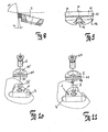
- the milling tool consists of the support body 3 with the cutting elements 1 inserted therein in recesses 2, which are screwed by means of countersunk screws 6 with the support body 3. Before each cutting element 1 is a chip space 4 for receiving the resulting chips in the machining of workpieces.
- FIG. 1 it can be seen that the outer cutting elements 1 are arranged in axially open recesses 2 and are not guided on its axially outer circumferential wall. The cutting elements 1 are arranged so that from the individual cutting edges 11 forms a spiral-shaped overall cutting edge.
- the milling tool can be connected to a drive shaft of a machining tool not shown here.
- Each cutting element 1 has a symmetrical shape which tapers towards the side opposite the cutting edge 11 (cutting edge) and has a substantially triangular shape.
- the cutting edge 11 opposite region 12 is rounded with a constant radius and arranged concentrically to the mounting hole.
- Central is a counterbore 15 with a conical profile cross-section in the Countersink provided (see. FIGS. 3, 4 ).
- the conical region 15 ' may be convex in order to produce a defined line system with the conical head 61 of a countersunk screw 6 corresponding to the bore 15.
- FIG. 7 shows, the cutting edge 11 ends in the same radial height as the lateral surface 31 of the support body 3. It can also be provided that the top 19 of the cutting element 1 is flush with the lateral surface 31 of the support body 3.
- the centrally introduced into the mirror-symmetrically shaped cutting element 1 bore 15 divides the groove 14 in two areas.
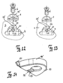
- a substantially corresponding to the shape of the cutting element 1 recess 2 is provided, which in the middle of its serving as a support surface bottom 21 at least one web 22 (see. FIG. 13 ) having.
- a threaded bore 23 is provided in the bottom 21, in which the countersunk screw 6 can be screwed.
- two webs 22 may be provided which are separated by the threaded bore 23 from each other.
- the cutting element 1 lies with its underside 13 flat on the bottom 21 of the recess 2.
- the cutting element 1 At its peripheral wall 16 'is the cutting element 1 only at the cutting edge 11 opposite rounding 12 with the wall 25 of the recess 2 in contact.
- the wall 25 of the recess 2 is formed flat, whereby in conjunction with the rounding of the cutting element 1, a defined line contact is formed.
- the positioning of the cutting element 1 is perpendicular to the cutting edge 11.
- the lateral positioning of the cutting element 1 via a side wall of the web 22.
- the groove 14 in the cutting element 1 and the web 22 in the recess 2 of the support body 3 are designed to correspond to each other with little play in the range of a few hundredths of a millimeter.
- the threaded hole 23 is not exactly centered in the recess 2, but offset such that the cutting element 1 at Tightening the central countersunk screw 6 is automatically pressed against the rear abutment (wall 25) and against one of the sides of the web 22.
- the center offset of the threaded hole 23 is in the range of 0.02 to 0.2 millimeters.
- the contact surface on the side of the web 22 is always selected depending on the axis angle of the cutting edge 11 so that the cutting element 1 is always supported during machining against the acting cutting forces. That is, regardless of the type of axial angle, there is only one cutting element 1.
- the central lateral positioning means of groove 14 and web 22, the recess 2 can be opened axially in the support body (see. FIGS. 10 to 13 combined with FIG. 1 ), so that the cutting element 1 can be installed flush or protruding to the supporting body 3, regardless of the direction in which the axis angle is provided.
- the groove 14 and the web 22 are divided by the holes 15 and 23 into two areas, so that the lateral positioning is not over the entire length of the cutting element 1, but over two spaced smaller contact surfaces, which has a positive effect on the positioning accuracy. It is particularly advantageous if the sides of the two web areas are convex or faceted. In this way, a line contact with the walls 17, 18 of the groove 14 is effected, whereby the positioning accuracy is less affected by contamination.
- the cutting element 1 is manufactured as a sintered part, only its underside 13 can be ground to reduce the manufacturing costs. In order to keep weight differences low, it is advantageous to additionally grind the top 19 to a defined thickness to the bottom 13. All other positioning surfaces can retain a sintered surface.
- the distance between the two lateral contact surfaces is reduced because the lateral positioning of the cutting element 1 via the groove 14, the positioning accuracy is increased.
- the distance between the groove walls 17, 18 in the cutting element 1 is approximately only 1/5 to 1/6 of the distance from right to left outer wall. Accordingly, the dimensional error also reduces to 1/5 to 1/6 of the dimensional error of the outer walls, so that the accuracy after sintering is sufficient and no additional grinding of the groove must be made.
- the groove flanks are inclined by 5 to 10 degrees. In this way, the pressed part can be formed better and is less susceptible to cracking during sintering.
- the cutting edges (cutting 11) of the cutting elements 1 can be finished in the installed state in the support body 3. This is done either by erosion (for example in polycrystalline diamond) or by grinding (eg in hard metal). By sharpening in the supporting body 3, the highest possible concentricity of the cutting 11 is achieved.
- the accuracy of cutting elements 1 and recesses 2 in the support body 3 is sufficiently high that the cutting edges 11 of the cutting elements 1 can be finished (sharpened) outside the support body as a single part.
- the cutting elements 1 are clamped in a recess 2 corresponding device (not shown) and sharpened therein.
- the cutting elements 1 are arranged in the support body that their milling tracks on the workpiece side by side and slightly overlap, so that a flat surface is achieved on the workpiece.
- the convex cutting profile of the entire tool is achieved in that the recesses 4 are arranged in the support body 3 in their position so that the envelope of the adjacent cutting edges 11 give the required hollow section.
- the cutting edge 11 In order to mill a flat surface at a given axis angle, the cutting edge 11 must be slightly convex with a very large radius R 1 profiled. To avoid sharp-edged markings of juxtaposed cutting edges on the milled workpiece surface, the cutting profile runs in the overlapping region with a smaller radius R 2 (cf. FIG. 9 ).
- the cutting element 1 terminates in the corresponding recess 2 of the support body 3 as flush as possible with the outer surface (lateral surface 31) of the support body 3, it must be installed as tangentially as possible.
- the cutting element 1 on the side of the cutting edge 11th an oblique portion formed so as to form the cutting edge itself or to be soldered thereto with a cutting edge (eg, polycrystalline diamond).
- the angle of the oblique region to the bearing surface of the cutting element 11 substantially corresponds to the rake angle SW in the installed state (see. FIG. 8 ).
- the rake angle SW changed such that it increases towards the trailing edge.
- the open space can in principle be produced according to two systems.
- FIG. 13 Particularly advantageous against large, acting on the cutting element 1 moments that can lead to a rotation, is an embodiment of the recess 2 in the support body 3 according to FIG. 13 , in which the rear stop is prismatic designed as a centering and the web 22 in the recess 2 only at the front of the cutting edge 11 serves as a moment support.
- FIG. 14 shows an embodiment of the cutting element 1, which in the recess 2 according to FIG. 13 can be used. Here it is not necessary that the groove 14 extends over the full length of the bottom 13.
Claims (15)
- Outil de fraisage pour l'usinage de matériaux non métalliques, en particulier du bois, un matériau dérivé du bois ou une matière plastique, comprenant un corps porteur (3), plusieurs éléments de coupe (1) qui peuvent y être insérés du côté périphérique dans un nombre correspondant d'évidements (2) s'étendant en direction radiale, et qui peuvent être vissés au corps porteur (3) par l'intermédiaire d'un alésage (15), les éléments de coupe étant réalisés en forme de plaquettes et sensiblement triangulaires en section transversale, et munis d'un tranchant (11) sur un bord latéral, la zone (12) opposée au tranchant (11) étant arrondie,
caractérisé par les particularités suivantes de l'élément de coupe (1) :a) il est prévu dans la face inférieure (13) une rainure (14) s'étendant sensiblement perpendiculairement au tranchant (11),b) l'alésage (15) subdivise la rainure (14) de préférence en deux zones,
et par les particularités suivantes de l'évidement (2) :c) une nervure (22) correspondant à la rainure (14) et qui s'étend vers le haut en direction radiale à partir du fond (21) de l'évidement, ce fond servant de surface d'appui pour l'élément de couple (1),d) un alésage taraudé radial (23) qui de préférence subdivise la nervure (22) en deux zones,
et en ce que :e) l'élément de coupe (1) n'a de contact avec l'évidement (2) que par la face inférieure (13) de l'élément de coupe, une paroi latérale (17 ou 18) de la rainure (14) et une partie de sa région arrondie opposée au tranchant (11). - Outil de fraisage selon la revendication 1, caractérisé en ce que sur sa paroi périphérique (16'), l'élément de coupe (1) ne présente qu'une zone de contact avec la paroi périphérique (25) de l'évidement (2).
- Outil de fraisage selon la revendication 1, caractérisé en ce que sur sa paroi périphérique (16'), l'élément de coupe (1) présente deux zones de contact avec la paroi périphérique (25) de l'évidement (2).
- Outil de fraisage selon la revendication 1, caractérisé en ce que l'élément de coupe (1) est réalisé avec une symétrie miroir par rapport à l'axe longitudinal (L) de la rainure (14).
- Outil de fraisage selon la revendication 1, caractérisé en ce que la rainure (14) s'étend sur toute la longueur de la face inférieure (13).
- Outil de fraisage selon l'une ou plusieurs des revendications 2 à 5, caractérisé en ce que le contact de la paroi périphérique (16') de l'élément de coupe (1), en sa région opposée au tranchant (11), avec l'évidement (2), est linéaire.
- Outil de fraisage selon la revendication 6, caractérisé en ce que la paroi (25) de l'évidement (2) est réalisée plane ou plate dans la région de contact.
- Outil de fraisage selon la revendication 1, caractérisé en ce que le corps porteur (3) est réalisé en métal léger, en particulier en aluminium.
- Outil de fraisage selon l'une ou plusieurs des revendications précédentes, caractérisé en ce que l'alésage taraudé (23) est disposé légèrement excentrique dans l'évidement (2).
- Outil de fraisage selon la revendication 9, caractérisé en ce que l'excentricité est dans la plage allant de 0,02 à 0,2 mm.
- Outil de fraisage selon l'une ou plusieurs des revendications précédentes, caractérisé en ce qu'au moins les tranchants (11) dans la zone de bord du corps porteur (3) sont insérés sous un angle axial dans le corps porteur (3) en vue de générer des forces pressantes sur une pièce d'oeuvre.
- Outil de fraisage selon l'une ou plusieurs des revendications précédentes, caractérisé en ce que l'élément de coupe (1) se termine de façon sensiblement jointive avec une face périphérique (31) du corps porteur (3).
- Outil de fraisage selon la revendication 1, caractérisé en ce que les plusieurs éléments de coupe (1) sont disposés de façon à générer lors d'une rotation du corps porteur (3) une courbe d'enveloppe convexe dont il résulte une surface concave dans la pièce d'oeuvre usinée.
- Outil de fraisage selon la revendication 1, caractérisé en ce qu'il est prévu une chambre à copeaux (4) en avant, relativement à la direction de rotation (D), de chaque élément de coupe (1).
- Élément de coupe pour un outil de fraisage, pour l'usinage de matériaux non métalliques, qui est réalisé sensiblement triangulaire, et comporte un corps de base (16) en forme de plaquette, symétrique par rapport à une ligne de symétrie (S), un tranchant (11) prévu sur le corps de base (16) à distance d'une face inférieure (13) du corps de base (16), et un alésage de fixation (15), la zone (12) opposée au tranchant (11) étant arrondie, caractérisé en ce que :a) une rainure (14) s'étendant sensiblement perpendiculairement au tranchant (11) est formée dans la face inférieure (13),b) l'axe longitudinal (L) de la rainure (14) coïncide avec la ligne de symétrie (S), etc) l'arête de coupe du tranchant (11) présente une courbure convexe et le rayon de courbure (R2) diminue dans les zones de bord opposées.
Priority Applications (1)
| Application Number | Priority Date | Filing Date | Title |
|---|---|---|---|
| PL10702394T PL2379290T3 (pl) | 2009-01-21 | 2010-01-06 | Narzędzie skrawające i element tnący narzędzia skrawającego |
Applications Claiming Priority (2)
| Application Number | Priority Date | Filing Date | Title |
|---|---|---|---|
| DE102009005634A DE102009005634B4 (de) | 2009-01-21 | 2009-01-21 | Fräswerkzeug und Schneidelement für ein Fräswerkzeug |
| PCT/DE2010/000004 WO2010083799A1 (fr) | 2009-01-21 | 2010-01-06 | Outil de fraisage et élément de coupe pour un outil de fraisage |
Publications (2)
| Publication Number | Publication Date |
|---|---|
| EP2379290A1 EP2379290A1 (fr) | 2011-10-26 |
| EP2379290B1 true EP2379290B1 (fr) | 2013-07-31 |
Family
ID=42111430
Family Applications (1)
| Application Number | Title | Priority Date | Filing Date |
|---|---|---|---|
| EP10702394.7A Active EP2379290B1 (fr) | 2009-01-21 | 2010-01-06 | Outil de fraisage et élément de coupe pour un outil de fraisage |
Country Status (10)
| Country | Link |
|---|---|
| US (1) | US9604290B2 (fr) |
| EP (1) | EP2379290B1 (fr) |
| CN (1) | CN102292196B (fr) |
| BR (1) | BRPI1007200B1 (fr) |
| DE (1) | DE102009005634B4 (fr) |
| DK (1) | DK2379290T3 (fr) |
| ES (1) | ES2427973T3 (fr) |
| PL (1) | PL2379290T3 (fr) |
| PT (1) | PT2379290E (fr) |
| WO (1) | WO2010083799A1 (fr) |
Families Citing this family (25)
| Publication number | Priority date | Publication date | Assignee | Title |
|---|---|---|---|---|
| EP3103575B1 (fr) | 2011-07-01 | 2020-02-12 | Ledermann GmbH & Co. KG | Outil d'usinage pour usinage par enlèvement de matière |
| BR112015010132B1 (pt) * | 2012-11-09 | 2021-09-21 | The Gleason Works | Cabeçote de cortador de face de engrenagem cônica para fresagem e faceamento de engrenagens cônicas e hipoides e método de retificação pelo menos uma lâmina de corte posicionada em um cabeçote de cortador de face de engrenagem cônica |
| WO2014093411A1 (fr) * | 2012-12-14 | 2014-06-19 | The Gleason Works | Tailleuse d'engrenages avec possibilité de réglage de lames carrées ou rectangulaires |
| US20140234038A1 (en) * | 2013-01-03 | 2014-08-21 | David Grover Freund | High shear cutting tool |
| US20140186129A1 (en) * | 2013-01-03 | 2014-07-03 | David Grover Freund | High shear cutting tool |
| CN103192434A (zh) * | 2013-04-09 | 2013-07-10 | 乐客精密工具(太仓)有限公司 | 金刚石剖面削式刀具 |
| US9266174B2 (en) * | 2013-06-10 | 2016-02-23 | sp3 Cutting Tools, Inc. | Cutting tool |
| CN104029259B (zh) * | 2014-04-22 | 2015-12-23 | 杭州和源精密工具有限公司 | 带限速刀片的可拆卸刀片式木工金刚石封边刀 |
| AT14191U1 (de) | 2014-06-05 | 2015-05-15 | Aigner Werkzeuge Ges M B H | Schneidelement für ein Fräswerkzeug |
| US9505066B2 (en) * | 2014-08-01 | 2016-11-29 | Kennametal Inc. | Rotary cutting tool with regrindable cutting inserts |
| EP3025814B1 (fr) * | 2014-11-28 | 2017-08-02 | Sandvik Intellectual Property AB | Insert de fraisage et outil de fraisage |
| JP6434534B2 (ja) * | 2014-12-17 | 2018-12-05 | 京セラ株式会社 | 切削インサート、切削工具及び切削加工物の製造方法 |
| PL3075477T3 (pl) * | 2015-04-01 | 2019-03-29 | Ledermann Gmbh & Co. Kg | Frez i element skrawający do zastosowania we frezie |
| US10384368B2 (en) * | 2015-07-27 | 2019-08-20 | Saber Diamond Tools Inc. | Contour rake face cutting tool |
| CN108884706B (zh) * | 2016-03-31 | 2021-05-04 | 斯伦贝谢技术有限公司 | 多脊切削元件 |
| JP6683261B2 (ja) * | 2016-10-21 | 2020-04-15 | 三菱日立ツール株式会社 | 切削インサート及び刃先交換式回転切削工具 |
| EP3354387A1 (fr) * | 2017-01-25 | 2018-08-01 | Ledermann GmbH & Co. KG | Outil d'enlèvement de copeaux |
| US10279400B2 (en) * | 2017-01-30 | 2019-05-07 | Iscar, Ltd. | Indexable, single-sided cutting insert having two clamping bores and cutting tool therefor |
| DE102017123681C5 (de) * | 2017-10-11 | 2022-01-27 | Leitz Gmbh & Co. Kg | Fräswerkzeug zum Bearbeiten von Holz, Holzwerkstoffen, Kunststoffen oder Leichtmetallen |
| CN112703076B (zh) * | 2018-09-12 | 2023-06-06 | 住友电工硬质合金株式会社 | 切削工具 |
| DE102018217939A1 (de) * | 2018-10-19 | 2020-04-23 | WOLFF GmbH & Co.KG | Fräswalze, Flächenfräse und Verfahren zur Entfernung von verklebten Bodenbelägen |
| DE102020109739A1 (de) | 2020-04-07 | 2021-10-07 | LEITZ GmbH & Co.KG | Werkzeug zur spanabhebenden Bearbeitung nicht metallischer Werkstoffe |
| TW202202250A (zh) * | 2020-07-02 | 2022-01-16 | 以色列商艾斯卡公司 | 具有鋸齒狀耦合部的可置換刀頭及其所使用的刀把 |
| CN114762902A (zh) * | 2021-01-15 | 2022-07-19 | 佛山市鑫运祥精密刀具有限公司 | 一种方便拆装的可换式预铣刀 |
| CN113305517B (zh) * | 2021-06-21 | 2022-10-11 | 成都爱乐达航空制造股份有限公司 | 一种筋条、缘条侧壁孔加工方法 |
Family Cites Families (28)
| Publication number | Priority date | Publication date | Assignee | Title |
|---|---|---|---|---|
| US1629667A (en) * | 1926-10-15 | 1927-05-24 | James D Knipple | Metal-cutting tool |
| US3629919A (en) * | 1969-09-17 | 1971-12-28 | David J Trevarrow Jr | Tool and tool holder assembly |
| US3829943A (en) * | 1971-02-19 | 1974-08-20 | Fansteel Inc | Threading tool |
| DE2935426A1 (de) | 1979-09-01 | 1981-03-26 | Günther 90491 Nürnberg Hertel | Schneidwerkzeug, z.b. schlitzfraeser oder raeumnadel |
| US4667713A (en) * | 1986-05-23 | 1987-05-26 | Weyerhaeuser Company | Chipper knife assembly |
| US4906145A (en) * | 1987-04-13 | 1990-03-06 | L. R. Oliver & Company, Inc. | Replaceable cutter blade |
| US5004378A (en) * | 1988-05-19 | 1991-04-02 | Mitsubishi Metal Corporation | Clamped cutting tool |
| JPH03228512A (ja) * | 1990-02-02 | 1991-10-09 | Hatarii Seimitsu Kogyo Kk | 追込カッター |
| CN1019557B (zh) * | 1990-02-07 | 1992-12-23 | Gn工具株式会社 | 带螺旋齿的切削刀具及其制造方法 |
| JP2556393B2 (ja) | 1990-02-07 | 1996-11-20 | ジーエヌツール株式会社 | ねじれ刃を有する切削工具及びその製造方法 |
| US5002104A (en) * | 1990-02-22 | 1991-03-26 | Stewart John S | Cutterhead for an industrial woodworking machine |
| SE9300889L (sv) * | 1993-03-18 | 1994-09-19 | Sandvik Ab | Fräskropp |
| DE4423861A1 (de) * | 1993-05-28 | 1994-12-01 | Holger Groeschel | Befestigungsvorrichtung für auswechselbare, mit zylindrischem Zapfen versehene Schneideinsätze |
| US5924826A (en) * | 1994-04-27 | 1999-07-20 | Sandvik Ab | Cutting insert mounted on holder by rib-and-groove coupling |
| EP0688638B1 (fr) * | 1994-06-20 | 1997-12-10 | Oertli Werkzeuge Ag | Fraise pour travailler le bois, en particulier disque de rainurage ou de profilage |
| US5494338A (en) | 1994-06-24 | 1996-02-27 | Deere & Company | Vehicle drive wheel |
| US5542795A (en) * | 1995-01-30 | 1996-08-06 | Kennametal Inc. | Plunge and face milling cutter with universal insert seats |
| US5603365A (en) | 1995-11-16 | 1997-02-18 | Stewart; John S. | Removable cutting blades for a helical cutterhead |
| IL128649A (en) * | 1999-02-22 | 2001-04-30 | Iscar Ltd | Cutting and applying tools for him |
| EP1210198A4 (fr) * | 1999-07-30 | 2007-12-19 | Nap Tools Llc | Montage et procede d'insertion pour organe de coupe |
| CN2429286Y (zh) * | 2000-07-07 | 2001-05-09 | 张维克 | 铁路车钩、钩尾框、钩舌四孔铣刀 |
| IL158497A (en) * | 2003-10-20 | 2008-03-20 | Gil Hecht | A tool for removing scratches and cutting for it |
| SE527851C2 (sv) * | 2004-02-11 | 2006-06-20 | Sandvik Intellectual Property | Skärverktyg, skär samt del till skärverktyg med serrationskopplingsytor |
| DE202004008642U1 (de) | 2004-05-27 | 2005-09-29 | Kennametal Inc. | Fräswerkzeug |
| US7325471B2 (en) * | 2004-09-07 | 2008-02-05 | Kennametal Inc. | Toolholder and cutting insert for a toolholder assembly |
| IL165621A (en) * | 2004-12-07 | 2008-06-05 | Iscar Ltd | Cutting tool and cutting tool for it |
| IL166007A (en) * | 2004-12-27 | 2009-02-11 | Iscar Ltd | Scraping tool and cutting tool for it |
| DE202005013360U1 (de) * | 2005-08-23 | 2006-12-28 | Kennametal Widia Produktions Gmbh & Co. Kg | Fräsmesserkopf |
-
2009
- 2009-01-21 DE DE102009005634A patent/DE102009005634B4/de active Active
-
2010
- 2010-01-06 EP EP10702394.7A patent/EP2379290B1/fr active Active
- 2010-01-06 PT PT107023947T patent/PT2379290E/pt unknown
- 2010-01-06 DK DK10702394.7T patent/DK2379290T3/da active
- 2010-01-06 PL PL10702394T patent/PL2379290T3/pl unknown
- 2010-01-06 CN CN201080004882.9A patent/CN102292196B/zh active Active
- 2010-01-06 BR BRPI1007200-4A patent/BRPI1007200B1/pt active IP Right Grant
- 2010-01-06 WO PCT/DE2010/000004 patent/WO2010083799A1/fr active Application Filing
- 2010-01-06 US US13/145,625 patent/US9604290B2/en active Active
- 2010-01-06 ES ES10702394T patent/ES2427973T3/es active Active
Also Published As
| Publication number | Publication date |
|---|---|
| DE102009005634B4 (de) | 2012-03-01 |
| PL2379290T3 (pl) | 2013-12-31 |
| BRPI1007200B1 (pt) | 2022-02-22 |
| DK2379290T3 (da) | 2013-10-21 |
| US20110305533A1 (en) | 2011-12-15 |
| EP2379290A1 (fr) | 2011-10-26 |
| US9604290B2 (en) | 2017-03-28 |
| BRPI1007200A2 (pt) | 2021-03-23 |
| DE102009005634A1 (de) | 2010-07-22 |
| ES2427973T3 (es) | 2013-11-05 |
| CN102292196A (zh) | 2011-12-21 |
| CN102292196B (zh) | 2016-05-11 |
| WO2010083799A1 (fr) | 2010-07-29 |
| PT2379290E (pt) | 2013-10-16 |
Similar Documents
| Publication | Publication Date | Title |
|---|---|---|
| EP2379290B1 (fr) | Outil de fraisage et élément de coupe pour un outil de fraisage | |
| EP0558811B1 (fr) | Alésoir à plaquette unique | |
| DE102006016290C5 (de) | Mehrteiliges Schaftwerkzeug, insbesondere Feinbearbeitungswerkzeug | |
| EP2234746B1 (fr) | Outil de perçage | |
| DE2502183B2 (de) | Einlippenbohrer | |
| EP3204202B1 (fr) | Tête de lame permettant l'usinage de matériau par enlèvement de copeaux et lame servant audit usinage | |
| DE102011013789B3 (de) | Schneidkluppe | |
| EP0084607A2 (fr) | Outil de fraisage | |
| EP1529587B1 (fr) | Alésoir de machine, tête d'outil et queue | |
| EP2307163A1 (fr) | Outil de coupe rotatif équipé d un élément de support | |
| EP1296793B1 (fr) | Outil de percage | |
| WO2005077575A9 (fr) | Procede d'usinage par enlevement de copeaux de trous de precision | |
| WO2012013425A1 (fr) | Outil pour le rodage de positionnement | |
| WO2005077575A2 (fr) | Procede d'usinage par enlevement de copeaux de trous de precision | |
| EP1693132A1 (fr) | Système de montage de plaquettes de coupe | |
| EP0264642B1 (fr) | Outil de coupe pour l'usinage de métaux par enlèvement de copeaux en particulier outil de rainurage | |
| EP0485546B1 (fr) | Garniture de coupe pour outils | |
| EP2464479B1 (fr) | Outil de fraisage, en particulier outil de fraisage à fileter | |
| WO2013037916A1 (fr) | Outil d'alésage ainsi que vis de réglage pour un mécanisme de réglage fin, notamment chez un outil d'alésage | |
| EP3137248B1 (fr) | Outil d'usinage par enlèvement de copeaux équipé de barres de guidage fixes et montées de manière élastique | |
| DE3411557A1 (de) | Schneidwerkzeug zum herstellen von loechern | |
| DE10333621B4 (de) | Schneideinsatz | |
| DE102005011000A1 (de) | Werkzeug zur Feinbearbeitung von Bohrungsoberflächen | |
| WO2013041075A1 (fr) | Cassette d'outil et outil d'usinage par enlèvement de copeaux comportant une cassette d'outil | |
| DE102013004394B4 (de) | Schneidplatte und Fräswerkzeug mit Schneidplatte |
Legal Events
| Date | Code | Title | Description |
|---|---|---|---|
| PUAI | Public reference made under article 153(3) epc to a published international application that has entered the european phase |
Free format text: ORIGINAL CODE: 0009012 |
|
| 17P | Request for examination filed |
Effective date: 20110722 |
|
| AK | Designated contracting states |
Kind code of ref document: A1 Designated state(s): AT BE BG CH CY CZ DE DK EE ES FI FR GB GR HR HU IE IS IT LI LT LU LV MC MK MT NL NO PL PT RO SE SI SK SM TR |
|
| DAX | Request for extension of the european patent (deleted) | ||
| GRAP | Despatch of communication of intention to grant a patent |
Free format text: ORIGINAL CODE: EPIDOSNIGR1 |
|
| GRAS | Grant fee paid |
Free format text: ORIGINAL CODE: EPIDOSNIGR3 |
|
| GRAA | (expected) grant |
Free format text: ORIGINAL CODE: 0009210 |
|
| AK | Designated contracting states |
Kind code of ref document: B1 Designated state(s): AT BE BG CH CY CZ DE DK EE ES FI FR GB GR HR HU IE IS IT LI LT LU LV MC MK MT NL NO PL PT RO SE SI SK SM TR |
|
| REG | Reference to a national code |
Ref country code: GB Ref legal event code: FG4D Free format text: NOT ENGLISH Ref country code: CH Ref legal event code: EP |
|
| REG | Reference to a national code |
Ref country code: AT Ref legal event code: REF Ref document number: 624336 Country of ref document: AT Kind code of ref document: T Effective date: 20130815 |
|
| REG | Reference to a national code |
Ref country code: IE Ref legal event code: FG4D Free format text: LANGUAGE OF EP DOCUMENT: GERMAN |
|
| REG | Reference to a national code |
Ref country code: DE Ref legal event code: R096 Ref document number: 502010004199 Country of ref document: DE Effective date: 20130926 |
|
| REG | Reference to a national code |
Ref country code: PT Ref legal event code: SC4A Free format text: AVAILABILITY OF NATIONAL TRANSLATION Effective date: 20131008 |
|
| REG | Reference to a national code |
Ref country code: DK Ref legal event code: T3 Effective date: 20131017 Ref country code: DK Ref legal event code: T3 |
|
| REG | Reference to a national code |
Ref country code: ES Ref legal event code: FG2A Ref document number: 2427973 Country of ref document: ES Kind code of ref document: T3 Effective date: 20131105 |
|
| REG | Reference to a national code |
Ref country code: NL Ref legal event code: VDEP Effective date: 20130731 |
|
| REG | Reference to a national code |
Ref country code: LT Ref legal event code: MG4D |
|
| REG | Reference to a national code |
Ref country code: PL Ref legal event code: T3 |
|
| PG25 | Lapsed in a contracting state [announced via postgrant information from national office to epo] |
Ref country code: NO Free format text: LAPSE BECAUSE OF FAILURE TO SUBMIT A TRANSLATION OF THE DESCRIPTION OR TO PAY THE FEE WITHIN THE PRESCRIBED TIME-LIMIT Effective date: 20131031 Ref country code: CY Free format text: LAPSE BECAUSE OF FAILURE TO SUBMIT A TRANSLATION OF THE DESCRIPTION OR TO PAY THE FEE WITHIN THE PRESCRIBED TIME-LIMIT Effective date: 20130724 Ref country code: SE Free format text: LAPSE BECAUSE OF FAILURE TO SUBMIT A TRANSLATION OF THE DESCRIPTION OR TO PAY THE FEE WITHIN THE PRESCRIBED TIME-LIMIT Effective date: 20130731 Ref country code: LT Free format text: LAPSE BECAUSE OF FAILURE TO SUBMIT A TRANSLATION OF THE DESCRIPTION OR TO PAY THE FEE WITHIN THE PRESCRIBED TIME-LIMIT Effective date: 20130731 Ref country code: IS Free format text: LAPSE BECAUSE OF FAILURE TO SUBMIT A TRANSLATION OF THE DESCRIPTION OR TO PAY THE FEE WITHIN THE PRESCRIBED TIME-LIMIT Effective date: 20131130 Ref country code: HR Free format text: LAPSE BECAUSE OF FAILURE TO SUBMIT A TRANSLATION OF THE DESCRIPTION OR TO PAY THE FEE WITHIN THE PRESCRIBED TIME-LIMIT Effective date: 20130731 |
|
| PG25 | Lapsed in a contracting state [announced via postgrant information from national office to epo] |
Ref country code: FI Free format text: LAPSE BECAUSE OF FAILURE TO SUBMIT A TRANSLATION OF THE DESCRIPTION OR TO PAY THE FEE WITHIN THE PRESCRIBED TIME-LIMIT Effective date: 20130731 Ref country code: SI Free format text: LAPSE BECAUSE OF FAILURE TO SUBMIT A TRANSLATION OF THE DESCRIPTION OR TO PAY THE FEE WITHIN THE PRESCRIBED TIME-LIMIT Effective date: 20130731 Ref country code: LV Free format text: LAPSE BECAUSE OF FAILURE TO SUBMIT A TRANSLATION OF THE DESCRIPTION OR TO PAY THE FEE WITHIN THE PRESCRIBED TIME-LIMIT Effective date: 20130731 Ref country code: GR Free format text: LAPSE BECAUSE OF FAILURE TO SUBMIT A TRANSLATION OF THE DESCRIPTION OR TO PAY THE FEE WITHIN THE PRESCRIBED TIME-LIMIT Effective date: 20131101 Ref country code: NL Free format text: LAPSE BECAUSE OF FAILURE TO SUBMIT A TRANSLATION OF THE DESCRIPTION OR TO PAY THE FEE WITHIN THE PRESCRIBED TIME-LIMIT Effective date: 20130731 |
|
| PG25 | Lapsed in a contracting state [announced via postgrant information from national office to epo] |
Ref country code: CY Free format text: LAPSE BECAUSE OF FAILURE TO SUBMIT A TRANSLATION OF THE DESCRIPTION OR TO PAY THE FEE WITHIN THE PRESCRIBED TIME-LIMIT Effective date: 20130731 |
|
| PG25 | Lapsed in a contracting state [announced via postgrant information from national office to epo] |
Ref country code: RO Free format text: LAPSE BECAUSE OF FAILURE TO SUBMIT A TRANSLATION OF THE DESCRIPTION OR TO PAY THE FEE WITHIN THE PRESCRIBED TIME-LIMIT Effective date: 20130731 Ref country code: SK Free format text: LAPSE BECAUSE OF FAILURE TO SUBMIT A TRANSLATION OF THE DESCRIPTION OR TO PAY THE FEE WITHIN THE PRESCRIBED TIME-LIMIT Effective date: 20130731 Ref country code: EE Free format text: LAPSE BECAUSE OF FAILURE TO SUBMIT A TRANSLATION OF THE DESCRIPTION OR TO PAY THE FEE WITHIN THE PRESCRIBED TIME-LIMIT Effective date: 20130731 Ref country code: CZ Free format text: LAPSE BECAUSE OF FAILURE TO SUBMIT A TRANSLATION OF THE DESCRIPTION OR TO PAY THE FEE WITHIN THE PRESCRIBED TIME-LIMIT Effective date: 20130731 |
|
| PLBE | No opposition filed within time limit |
Free format text: ORIGINAL CODE: 0009261 |
|
| STAA | Information on the status of an ep patent application or granted ep patent |
Free format text: STATUS: NO OPPOSITION FILED WITHIN TIME LIMIT |
|
| 26N | No opposition filed |
Effective date: 20140502 |
|
| REG | Reference to a national code |
Ref country code: DE Ref legal event code: R097 Ref document number: 502010004199 Country of ref document: DE Effective date: 20140502 |
|
| PG25 | Lapsed in a contracting state [announced via postgrant information from national office to epo] |
Ref country code: LU Free format text: LAPSE BECAUSE OF FAILURE TO SUBMIT A TRANSLATION OF THE DESCRIPTION OR TO PAY THE FEE WITHIN THE PRESCRIBED TIME-LIMIT Effective date: 20140106 |
|
| REG | Reference to a national code |
Ref country code: CH Ref legal event code: PL |
|
| GBPC | Gb: european patent ceased through non-payment of renewal fee |
Effective date: 20140106 |
|
| PG25 | Lapsed in a contracting state [announced via postgrant information from national office to epo] |
Ref country code: LI Free format text: LAPSE BECAUSE OF NON-PAYMENT OF DUE FEES Effective date: 20140131 Ref country code: CH Free format text: LAPSE BECAUSE OF NON-PAYMENT OF DUE FEES Effective date: 20140131 |
|
| REG | Reference to a national code |
Ref country code: IE Ref legal event code: MM4A |
|
| PG25 | Lapsed in a contracting state [announced via postgrant information from national office to epo] |
Ref country code: GB Free format text: LAPSE BECAUSE OF NON-PAYMENT OF DUE FEES Effective date: 20140106 |
|
| PG25 | Lapsed in a contracting state [announced via postgrant information from national office to epo] |
Ref country code: IE Free format text: LAPSE BECAUSE OF NON-PAYMENT OF DUE FEES Effective date: 20140106 |
|
| PG25 | Lapsed in a contracting state [announced via postgrant information from national office to epo] |
Ref country code: MC Free format text: LAPSE BECAUSE OF FAILURE TO SUBMIT A TRANSLATION OF THE DESCRIPTION OR TO PAY THE FEE WITHIN THE PRESCRIBED TIME-LIMIT Effective date: 20130731 |
|
| REG | Reference to a national code |
Ref country code: DE Ref legal event code: R082 Ref document number: 502010004199 Country of ref document: DE Representative=s name: GRAMM, LINS & PARTNER PATENT- UND RECHTSANWAEL, DE |
|
| REG | Reference to a national code |
Ref country code: FR Ref legal event code: PLFP Year of fee payment: 7 |
|
| PG25 | Lapsed in a contracting state [announced via postgrant information from national office to epo] |
Ref country code: MT Free format text: LAPSE BECAUSE OF FAILURE TO SUBMIT A TRANSLATION OF THE DESCRIPTION OR TO PAY THE FEE WITHIN THE PRESCRIBED TIME-LIMIT Effective date: 20130731 |
|
| PG25 | Lapsed in a contracting state [announced via postgrant information from national office to epo] |
Ref country code: SM Free format text: LAPSE BECAUSE OF FAILURE TO SUBMIT A TRANSLATION OF THE DESCRIPTION OR TO PAY THE FEE WITHIN THE PRESCRIBED TIME-LIMIT Effective date: 20130731 |
|
| PG25 | Lapsed in a contracting state [announced via postgrant information from national office to epo] |
Ref country code: BG Free format text: LAPSE BECAUSE OF FAILURE TO SUBMIT A TRANSLATION OF THE DESCRIPTION OR TO PAY THE FEE WITHIN THE PRESCRIBED TIME-LIMIT Effective date: 20130731 |
|
| PG25 | Lapsed in a contracting state [announced via postgrant information from national office to epo] |
Ref country code: HU Free format text: LAPSE BECAUSE OF FAILURE TO SUBMIT A TRANSLATION OF THE DESCRIPTION OR TO PAY THE FEE WITHIN THE PRESCRIBED TIME-LIMIT; INVALID AB INITIO Effective date: 20100106 |
|
| REG | Reference to a national code |
Ref country code: FR Ref legal event code: PLFP Year of fee payment: 8 |
|
| REG | Reference to a national code |
Ref country code: FR Ref legal event code: PLFP Year of fee payment: 9 |
|
| PG25 | Lapsed in a contracting state [announced via postgrant information from national office to epo] |
Ref country code: MK Free format text: LAPSE BECAUSE OF FAILURE TO SUBMIT A TRANSLATION OF THE DESCRIPTION OR TO PAY THE FEE WITHIN THE PRESCRIBED TIME-LIMIT Effective date: 20130731 |
|
| PGFP | Annual fee paid to national office [announced via postgrant information from national office to epo] |
Ref country code: PT Payment date: 20191227 Year of fee payment: 11 Ref country code: DK Payment date: 20200123 Year of fee payment: 11 |
|
| PGFP | Annual fee paid to national office [announced via postgrant information from national office to epo] |
Ref country code: BE Payment date: 20200122 Year of fee payment: 11 |
|
| REG | Reference to a national code |
Ref country code: DK Ref legal event code: EBP Effective date: 20210131 |
|
| REG | Reference to a national code |
Ref country code: BE Ref legal event code: MM Effective date: 20210131 |
|
| PG25 | Lapsed in a contracting state [announced via postgrant information from national office to epo] |
Ref country code: PT Free format text: LAPSE BECAUSE OF NON-PAYMENT OF DUE FEES Effective date: 20210706 |
|
| PG25 | Lapsed in a contracting state [announced via postgrant information from national office to epo] |
Ref country code: DK Free format text: LAPSE BECAUSE OF NON-PAYMENT OF DUE FEES Effective date: 20210131 |
|
| PG25 | Lapsed in a contracting state [announced via postgrant information from national office to epo] |
Ref country code: BE Free format text: LAPSE BECAUSE OF NON-PAYMENT OF DUE FEES Effective date: 20210131 |
|
| PGFP | Annual fee paid to national office [announced via postgrant information from national office to epo] |
Ref country code: PL Payment date: 20221223 Year of fee payment: 14 |
|
| PGFP | Annual fee paid to national office [announced via postgrant information from national office to epo] |
Ref country code: FR Payment date: 20230123 Year of fee payment: 14 Ref country code: ES Payment date: 20230216 Year of fee payment: 14 Ref country code: AT Payment date: 20230118 Year of fee payment: 14 |
|
| PGFP | Annual fee paid to national office [announced via postgrant information from national office to epo] |
Ref country code: TR Payment date: 20230102 Year of fee payment: 14 Ref country code: IT Payment date: 20230131 Year of fee payment: 14 Ref country code: DE Payment date: 20221228 Year of fee payment: 14 |
|
| P01 | Opt-out of the competence of the unified patent court (upc) registered |
Effective date: 20230605 |
|
| PGFP | Annual fee paid to national office [announced via postgrant information from national office to epo] |
Ref country code: PL Payment date: 20231222 Year of fee payment: 15 |
|
| PGFP | Annual fee paid to national office [announced via postgrant information from national office to epo] |
Ref country code: ES Payment date: 20240216 Year of fee payment: 15 |
|
| PGFP | Annual fee paid to national office [announced via postgrant information from national office to epo] |
Ref country code: AT Payment date: 20240118 Year of fee payment: 15 |