EP2379290B1 - Milling tool and cutting element for a milling tool - Google Patents
Milling tool and cutting element for a milling tool Download PDFInfo
- Publication number
- EP2379290B1 EP2379290B1 EP10702394.7A EP10702394A EP2379290B1 EP 2379290 B1 EP2379290 B1 EP 2379290B1 EP 10702394 A EP10702394 A EP 10702394A EP 2379290 B1 EP2379290 B1 EP 2379290B1
- Authority
- EP
- European Patent Office
- Prior art keywords
- cutting element
- milling tool
- cutting
- tool according
- recess
- Prior art date
- Legal status (The legal status is an assumption and is not a legal conclusion. Google has not performed a legal analysis and makes no representation as to the accuracy of the status listed.)
- Active
Links
- 238000005520 cutting process Methods 0.000 title claims description 193
- 238000003801 milling Methods 0.000 title claims description 38
- 238000003754 machining Methods 0.000 claims description 8
- 239000000463 material Substances 0.000 claims description 8
- 239000002023 wood Substances 0.000 claims description 4
- 229910052782 aluminium Inorganic materials 0.000 claims description 2
- XAGFODPZIPBFFR-UHFFFAOYSA-N aluminium Chemical compound [Al] XAGFODPZIPBFFR-UHFFFAOYSA-N 0.000 claims description 2
- 230000007423 decrease Effects 0.000 claims 1
- 229910001234 light alloy Inorganic materials 0.000 claims 1
- 230000002093 peripheral effect Effects 0.000 description 8
- 238000004519 manufacturing process Methods 0.000 description 5
- 229910052751 metal Inorganic materials 0.000 description 4
- 239000002184 metal Substances 0.000 description 4
- 229910003460 diamond Inorganic materials 0.000 description 3
- 239000010432 diamond Substances 0.000 description 3
- 238000005245 sintering Methods 0.000 description 3
- 238000000227 grinding Methods 0.000 description 2
- 239000007769 metal material Substances 0.000 description 2
- 230000001154 acute effect Effects 0.000 description 1
- 238000004026 adhesive bonding Methods 0.000 description 1
- 238000005219 brazing Methods 0.000 description 1
- 238000011109 contamination Methods 0.000 description 1
- 238000005336 cracking Methods 0.000 description 1
- 230000007547 defect Effects 0.000 description 1
- 230000001627 detrimental effect Effects 0.000 description 1
- 238000005553 drilling Methods 0.000 description 1
- 230000003628 erosive effect Effects 0.000 description 1
- 239000003292 glue Substances 0.000 description 1
- 238000009434 installation Methods 0.000 description 1
- 238000005304 joining Methods 0.000 description 1
- 230000008092 positive effect Effects 0.000 description 1
- 238000003825 pressing Methods 0.000 description 1
- 238000007493 shaping process Methods 0.000 description 1
- 238000005476 soldering Methods 0.000 description 1
- 230000000007 visual effect Effects 0.000 description 1
Images


Classifications
-
- B—PERFORMING OPERATIONS; TRANSPORTING
- B23—MACHINE TOOLS; METAL-WORKING NOT OTHERWISE PROVIDED FOR
- B23C—MILLING
- B23C5/00—Milling-cutters
- B23C5/02—Milling-cutters characterised by the shape of the cutter
- B23C5/04—Plain cutters, i.e. having essentially a cylindrical or tapered cutting surface of substantial length
-
- B—PERFORMING OPERATIONS; TRANSPORTING
- B23—MACHINE TOOLS; METAL-WORKING NOT OTHERWISE PROVIDED FOR
- B23C—MILLING
- B23C5/00—Milling-cutters
- B23C5/16—Milling-cutters characterised by physical features other than shape
- B23C5/20—Milling-cutters characterised by physical features other than shape with removable cutter bits or teeth or cutting inserts
- B23C5/22—Securing arrangements for bits or teeth or cutting inserts
- B23C5/2204—Securing arrangements for bits or teeth or cutting inserts with cutting inserts clamped against the walls of the recess in the cutter body by a clamping member acting upon the wall of a hole in the insert
- B23C5/2208—Securing arrangements for bits or teeth or cutting inserts with cutting inserts clamped against the walls of the recess in the cutter body by a clamping member acting upon the wall of a hole in the insert for plate-like cutting inserts
- B23C5/2213—Securing arrangements for bits or teeth or cutting inserts with cutting inserts clamped against the walls of the recess in the cutter body by a clamping member acting upon the wall of a hole in the insert for plate-like cutting inserts having a special shape
-
- B—PERFORMING OPERATIONS; TRANSPORTING
- B27—WORKING OR PRESERVING WOOD OR SIMILAR MATERIAL; NAILING OR STAPLING MACHINES IN GENERAL
- B27G—ACCESSORY MACHINES OR APPARATUS FOR WORKING WOOD OR SIMILAR MATERIALS; TOOLS FOR WORKING WOOD OR SIMILAR MATERIALS; SAFETY DEVICES FOR WOOD WORKING MACHINES OR TOOLS
- B27G13/00—Cutter blocks; Other rotary cutting tools
- B27G13/02—Cutter blocks; Other rotary cutting tools in the shape of long arbors, i.e. cylinder cutting blocks
- B27G13/04—Securing the cutters by mechanical clamping means
-
- B—PERFORMING OPERATIONS; TRANSPORTING
- B23—MACHINE TOOLS; METAL-WORKING NOT OTHERWISE PROVIDED FOR
- B23C—MILLING
- B23C2200/00—Details of milling cutting inserts
- B23C2200/04—Overall shape
- B23C2200/0416—Irregular
-
- B—PERFORMING OPERATIONS; TRANSPORTING
- B23—MACHINE TOOLS; METAL-WORKING NOT OTHERWISE PROVIDED FOR
- B23C—MILLING
- B23C2200/00—Details of milling cutting inserts
- B23C2200/16—Supporting or bottom surfaces
- B23C2200/165—Supporting or bottom surfaces with one or more grooves
-
- B—PERFORMING OPERATIONS; TRANSPORTING
- B23—MACHINE TOOLS; METAL-WORKING NOT OTHERWISE PROVIDED FOR
- B23C—MILLING
- B23C2210/00—Details of milling cutters
- B23C2210/16—Fixation of inserts or cutting bits in the tool
- B23C2210/168—Seats for cutting inserts, supports for replacable cutting bits
-
- B—PERFORMING OPERATIONS; TRANSPORTING
- B23—MACHINE TOOLS; METAL-WORKING NOT OTHERWISE PROVIDED FOR
- B23C—MILLING
- B23C2226/00—Materials of tools or workpieces not comprising a metal
- B23C2226/31—Diamond
- B23C2226/315—Diamond polycrystalline [PCD]
-
- Y—GENERAL TAGGING OF NEW TECHNOLOGICAL DEVELOPMENTS; GENERAL TAGGING OF CROSS-SECTIONAL TECHNOLOGIES SPANNING OVER SEVERAL SECTIONS OF THE IPC; TECHNICAL SUBJECTS COVERED BY FORMER USPC CROSS-REFERENCE ART COLLECTIONS [XRACs] AND DIGESTS
- Y10—TECHNICAL SUBJECTS COVERED BY FORMER USPC
- Y10T—TECHNICAL SUBJECTS COVERED BY FORMER US CLASSIFICATION
- Y10T407/00—Cutters, for shaping
- Y10T407/19—Rotary cutting tool
- Y10T407/1906—Rotary cutting tool including holder [i.e., head] having seat for inserted tool
- Y10T407/1934—Rotary cutting tool including holder [i.e., head] having seat for inserted tool with separate means to fasten tool to holder
- Y10T407/1936—Apertured tool
-
- Y—GENERAL TAGGING OF NEW TECHNOLOGICAL DEVELOPMENTS; GENERAL TAGGING OF CROSS-SECTIONAL TECHNOLOGIES SPANNING OVER SEVERAL SECTIONS OF THE IPC; TECHNICAL SUBJECTS COVERED BY FORMER USPC CROSS-REFERENCE ART COLLECTIONS [XRACs] AND DIGESTS
- Y10—TECHNICAL SUBJECTS COVERED BY FORMER USPC
- Y10T—TECHNICAL SUBJECTS COVERED BY FORMER US CLASSIFICATION
- Y10T407/00—Cutters, for shaping
- Y10T407/27—Cutters, for shaping comprising tool of specific chemical composition
Definitions
- the invention relates to a Fräswerkzeu, according to the preamble of claim 1, for machining non-metallic materials, in particular wood, wood material and plastic, with a supporting body, a plurality therein circumferentially in a corresponding number in the radial direction extending recesses usable, via a bore the support body screwed cutting elements, the plate-shaped and formed in cross-section substantially triangular and are provided on a cutting edge with a cutting edge.
- the invention also relates to a cutting element for a milling tool having the features of the preamble of claim 15.
- Such a milling tool and a cutting element usable herewith are for example from EP 0 861 144 B1 or the US 6,659,694 B1 known.
- individual cutting elements are fixed by a central screw tangentially to the lateral surface of the support body in a recess which is designed so that the cutting element abuts with its outer edges (peripheral wall) at three locations in the recess and supported against the acting cutting forces becomes.
- the individual cutting elements are arranged so that the individual cutting edges in the tool carrier body form a continuous cutting spiral.
- the support body In order to fix the edge cutting edges with an axis angle to the tool center plane, the support body must be formed beyond the cutting area of the cutting element, so that sufficient space for the recess for receiving the edge cutting element is present. Because the cutting elements are to be positioned in their associated recesses so that they are supported against acting cutting forces, the support body must therefore enclose the edge cutting elements, ie extend beyond the cutting element. In order to achieve a high concentricity and an accurate alignment of the adjacent cutting elements in a continuous spiral, the outer edges of the cutting elements (contact surfaces) must be ground high precision or the cutting edges as a whole in the installed state of the cutting elements in the support body are ground continuously.
- the milling tool described above is to be trained so that the noise is reduced and the weight is reduced at a given cutting circle diameter and the space available in a machine only limited space is optimally utilized.
- the lateral positioning of the cutting elements does not take place via the outer contour but via a central groove. This makes it possible to complete the cutting elements laterally flush with the support body regardless of their axial angle or to let it protrude beyond it.
- the cutting element has at its peripheral wall only a contact area with the peripheral wall of the recess.
- the cutting element preferably has on its peripheral wall two contact areas with the peripheral wall of the recess.
- the cutting element is mirror-symmetrical to the longitudinal axis of the groove, not only its production, but also the assembly in the support body is simplified.
- the groove preferably extends over the full length of the underside of the cutting element.
- the contact of the cutting element at its edge opposite the cutting area with the recess may preferably be linear.
- the wall of the recess in the contact region is flat (straight or planar).
- a defined line contact is thereby set.
- the positioning of the cutting element is perpendicular to the cutting edge.
- no contact with the peripheral wall of the cutting element is provided.
- the lateral positioning of the cutting element via a side wall of the web in the recess.
- the groove in the cutting element and the web in the recess of the support body are designed with little play in the range of a few hundredths of a millimeter.
- the support body is preferably made of light metal. In particular, preferably made of aluminum.
- the cutting element is automatically pressed against the rear abutment and against one of the web sides when tightening the central fastening screw.
- the eccentricity of the threaded bore is then preferably in a range between 0.02 and 0.2 millimeters.
- At least the cutting edges in the edge region of the support body are used to generate compressive forces on a workpiece at an axis angle in the support body.
- the contact surface on the web side is always selected such that the cutting element is always supported against the acting cutting forces.
- there is only one cutting element regardless of what kind of Achswinkeln it is provided. Due to the central lateral positioning means of groove and web, the recess in the support body can be opened laterally and the cutting element flush or protruding to the support body are installed, regardless of the direction in which the axis angle is provided.
- the plurality of cutting elements is arranged so that they generate a convex envelope upon rotation of the support body, from which results a (slightly) concave surface in the machined workpiece, and in particular is preferably viewed in the direction of rotation, before each cutting element each provided a chip space and a suitable for use in this milling cutter cutting element.
- a cutting element for a milling tool for machining non-metallic materials with a symmetrical to a line of symmetry, plate-shaped base body, a blade provided on the base and a mounting hole is characterized for problem solving the fact that the features of the Anspuchs 15 has.
- the groove is divided from the mounting hole in two areas. If the groove extends over the full length of the bottom, the production and in particular the assembly of the cutting element in the milling tool is simplified.
- the main body is preferably made of a sintered material, such as hard metal.
- the cutting edge may be integrally formed with the base body and made of the same material as the main body.
- the cutting edge consists of a harder material than the basic body, in particular preferably of a polycrystalline diamond. In this case, the cutting edge is then materially connected to the base body, for example by brazing or gluing.
- this is preferably protruding over the top of the body.
- the underside of the main body is ground in order to permit a planar support of the cutting element in the recess of the supporting body of the milling tool.
- the mounting hole is preferably designed with a conical countersink, which may be curved in particular convex.
- the cutting edge opposite the rounded portion of the cutting element preferably has a constant radius.
- the radius is preferably arranged concentrically to the mounting hole.
- the milling tool consists of the support body 3 with the cutting elements 1 inserted therein in recesses 2, which are screwed by means of countersunk screws 6 with the support body 3. Before each cutting element 1 is a chip space 4 for receiving the resulting chips in the machining of workpieces.
- FIG. 1 it can be seen that the outer cutting elements 1 are arranged in axially open recesses 2 and are not guided on its axially outer circumferential wall. The cutting elements 1 are arranged so that from the individual cutting edges 11 forms a spiral-shaped overall cutting edge.
- the milling tool can be connected to a drive shaft of a machining tool not shown here.
- Each cutting element 1 has a symmetrical shape which tapers towards the side opposite the cutting edge 11 (cutting edge) and has a substantially triangular shape.
- the cutting edge 11 opposite region 12 is rounded with a constant radius and arranged concentrically to the mounting hole.
- Central is a counterbore 15 with a conical profile cross-section in the Countersink provided (see. FIGS. 3, 4 ).
- the conical region 15 ' may be convex in order to produce a defined line system with the conical head 61 of a countersunk screw 6 corresponding to the bore 15.
- FIG. 7 shows, the cutting edge 11 ends in the same radial height as the lateral surface 31 of the support body 3. It can also be provided that the top 19 of the cutting element 1 is flush with the lateral surface 31 of the support body 3.
- the centrally introduced into the mirror-symmetrically shaped cutting element 1 bore 15 divides the groove 14 in two areas.
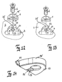
- a substantially corresponding to the shape of the cutting element 1 recess 2 is provided, which in the middle of its serving as a support surface bottom 21 at least one web 22 (see. FIG. 13 ) having.
- a threaded bore 23 is provided in the bottom 21, in which the countersunk screw 6 can be screwed.
- two webs 22 may be provided which are separated by the threaded bore 23 from each other.
- the cutting element 1 lies with its underside 13 flat on the bottom 21 of the recess 2.
- the cutting element 1 At its peripheral wall 16 'is the cutting element 1 only at the cutting edge 11 opposite rounding 12 with the wall 25 of the recess 2 in contact.
- the wall 25 of the recess 2 is formed flat, whereby in conjunction with the rounding of the cutting element 1, a defined line contact is formed.
- the positioning of the cutting element 1 is perpendicular to the cutting edge 11.
- the lateral positioning of the cutting element 1 via a side wall of the web 22.
- the groove 14 in the cutting element 1 and the web 22 in the recess 2 of the support body 3 are designed to correspond to each other with little play in the range of a few hundredths of a millimeter.
- the threaded hole 23 is not exactly centered in the recess 2, but offset such that the cutting element 1 at Tightening the central countersunk screw 6 is automatically pressed against the rear abutment (wall 25) and against one of the sides of the web 22.
- the center offset of the threaded hole 23 is in the range of 0.02 to 0.2 millimeters.
- the contact surface on the side of the web 22 is always selected depending on the axis angle of the cutting edge 11 so that the cutting element 1 is always supported during machining against the acting cutting forces. That is, regardless of the type of axial angle, there is only one cutting element 1.
- the central lateral positioning means of groove 14 and web 22, the recess 2 can be opened axially in the support body (see. FIGS. 10 to 13 combined with FIG. 1 ), so that the cutting element 1 can be installed flush or protruding to the supporting body 3, regardless of the direction in which the axis angle is provided.
- the groove 14 and the web 22 are divided by the holes 15 and 23 into two areas, so that the lateral positioning is not over the entire length of the cutting element 1, but over two spaced smaller contact surfaces, which has a positive effect on the positioning accuracy. It is particularly advantageous if the sides of the two web areas are convex or faceted. In this way, a line contact with the walls 17, 18 of the groove 14 is effected, whereby the positioning accuracy is less affected by contamination.
- the cutting element 1 is manufactured as a sintered part, only its underside 13 can be ground to reduce the manufacturing costs. In order to keep weight differences low, it is advantageous to additionally grind the top 19 to a defined thickness to the bottom 13. All other positioning surfaces can retain a sintered surface.
- the distance between the two lateral contact surfaces is reduced because the lateral positioning of the cutting element 1 via the groove 14, the positioning accuracy is increased.
- the distance between the groove walls 17, 18 in the cutting element 1 is approximately only 1/5 to 1/6 of the distance from right to left outer wall. Accordingly, the dimensional error also reduces to 1/5 to 1/6 of the dimensional error of the outer walls, so that the accuracy after sintering is sufficient and no additional grinding of the groove must be made.
- the groove flanks are inclined by 5 to 10 degrees. In this way, the pressed part can be formed better and is less susceptible to cracking during sintering.
- the cutting edges (cutting 11) of the cutting elements 1 can be finished in the installed state in the support body 3. This is done either by erosion (for example in polycrystalline diamond) or by grinding (eg in hard metal). By sharpening in the supporting body 3, the highest possible concentricity of the cutting 11 is achieved.
- the accuracy of cutting elements 1 and recesses 2 in the support body 3 is sufficiently high that the cutting edges 11 of the cutting elements 1 can be finished (sharpened) outside the support body as a single part.
- the cutting elements 1 are clamped in a recess 2 corresponding device (not shown) and sharpened therein.
- the cutting elements 1 are arranged in the support body that their milling tracks on the workpiece side by side and slightly overlap, so that a flat surface is achieved on the workpiece.
- the convex cutting profile of the entire tool is achieved in that the recesses 4 are arranged in the support body 3 in their position so that the envelope of the adjacent cutting edges 11 give the required hollow section.
- the cutting edge 11 In order to mill a flat surface at a given axis angle, the cutting edge 11 must be slightly convex with a very large radius R 1 profiled. To avoid sharp-edged markings of juxtaposed cutting edges on the milled workpiece surface, the cutting profile runs in the overlapping region with a smaller radius R 2 (cf. FIG. 9 ).
- the cutting element 1 terminates in the corresponding recess 2 of the support body 3 as flush as possible with the outer surface (lateral surface 31) of the support body 3, it must be installed as tangentially as possible.
- the cutting element 1 on the side of the cutting edge 11th an oblique portion formed so as to form the cutting edge itself or to be soldered thereto with a cutting edge (eg, polycrystalline diamond).
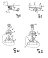
- the angle of the oblique region to the bearing surface of the cutting element 11 substantially corresponds to the rake angle SW in the installed state (see. FIG. 8 ).
- the rake angle SW changed such that it increases towards the trailing edge.
- the open space can in principle be produced according to two systems.
- FIG. 13 Particularly advantageous against large, acting on the cutting element 1 moments that can lead to a rotation, is an embodiment of the recess 2 in the support body 3 according to FIG. 13 , in which the rear stop is prismatic designed as a centering and the web 22 in the recess 2 only at the front of the cutting edge 11 serves as a moment support.
- FIG. 14 shows an embodiment of the cutting element 1, which in the recess 2 according to FIG. 13 can be used. Here it is not necessary that the groove 14 extends over the full length of the bottom 13.
Description
Die Erfindung betrifft ein Fräswerkzeu, gemäß dem Oberbegriffs des Anspruchs 1, zur Bearbeitung nicht metallischer Werkstoffe, insbesondere Holz, Holzwerkstoff und Kunststoff, mit einem Tragkörper, einer Mehrzahl darin umfangsseitig in eine entsprechende Anzahl sich in radiale Richtung erstreckenden Ausnehmungen einsetzbarer, über eine Bohrung mit dem Tragkörper verschraubbarer Schneidelemente, die plattenförmig und im Querschnitt im Wesentlichen dreieckförmig ausgebildet und an einer Schneidkante mit einer Schneide versehen sind.The invention relates to a Fräswerkzeu, according to the preamble of
Die Erfindung betrifft auch ein Schneidelement für ein Fräswerkzeug mit den Merkmalen des Oberbegriffs von Patentanspruch 15.The invention also relates to a cutting element for a milling tool having the features of the preamble of
Ein solches Fräswerkzeug und ein hiermit verwendbares Schneidelement sind beispielsweise aus der
Bei den bekannten Werkzeugen werden einzelne Schneidelemente durch eine zentrale Schraube tangential zur Mantelfläche des Tragkörpers in einer Ausnehmung befestigt, die so ausgeführt ist, dass das Schneidelement mit seinen Außenkanten (Umfangswandung) an drei Stellen in der Ausnehmung anliegt und gegen die einwirkenden Schnittkräfte abgestützt wird. Die einzelnen Schneidelemente sind so angeordnet, dass die Einzelschneiden im Werkzeugtragkörper eine durchgehende Schneidspirale bilden.In the known tools individual cutting elements are fixed by a central screw tangentially to the lateral surface of the support body in a recess which is designed so that the cutting element abuts with its outer edges (peripheral wall) at three locations in the recess and supported against the acting cutting forces becomes. The individual cutting elements are arranged so that the individual cutting edges in the tool carrier body form a continuous cutting spiral.
Um die Randschneiden mit einem Achswinkel zur Werkzeugmittelebene hin befestigen zu können, muss der Tragkörper über den Schneidenbereich des Schneidelementes hinaus ausgebildet sein, damit genügend Bauraum für die Ausnehmung zur Aufnahme des Randschneidelementes vorhanden ist. Weil die Schneidelemente so in ihren zugehörigen Ausnehmungen positioniert werden sollen, dass sie gegen einwirkende Schnittkräfte abgestützt sind, muss der Tragkörper die Randschneidelemente folglich umschließen, also über das Schneidelement hinausreichen. Um eine hohe Rundlaufgenauigkeit und eine exakte Fluchtung der nebeneinander liegenden Schneidelemente in einer durchgehenden Spirale zu erreichen, müssen die Außenkanten der Schneidelemente (Anlageflächen) hoch genau geschliffen sein oder die Schneidkanten als Ganzes im eingebauten Zustand der Schneidelemente im Tragkörper durchgehend geschliffen werden.In order to fix the edge cutting edges with an axis angle to the tool center plane, the support body must be formed beyond the cutting area of the cutting element, so that sufficient space for the recess for receiving the edge cutting element is present. Because the cutting elements are to be positioned in their associated recesses so that they are supported against acting cutting forces, the support body must therefore enclose the edge cutting elements, ie extend beyond the cutting element. In order to achieve a high concentricity and an accurate alignment of the adjacent cutting elements in a continuous spiral, the outer edges of the cutting elements (contact surfaces) must be ground high precision or the cutting edges as a whole in the installed state of the cutting elements in the support body are ground continuously.
In der Zeitschrift "
Es hat sich als vorteilhaft erwiesen, den Werkzeugtragkörper solcher Fräswerkzeuge möglichst zylindrisch auszuführen, um eine lärmarme Gestaltung zu erreichen, und außerdem die Schneiden nur gering über die Mantelfläche des Tragkörpers hervorstehen zu lassen sowie schmale, tiefe Spanräume zur Aufnahme des Spangutes während des Schnittvorganges vorzusehen. Derart lärmgeminderte Werkzeuge haben bei gleichem Schneidenflugkreisdurchmesser aufgrund des höheren Materialeinsatzes ein höheres Gewicht als konventionelle Fräswerkzeuge und sind aufgrund des geringen Schneidenüberstandes weniger häufig nachschärfbar. Insbesondere bei kleineren, leicht gebauten Maschinen wirkt sich die große Masse des Werkzeuges nachteilig auf die Bearbeitungsqualität und die Standwege aus, was auf das Schwingungsverhalten zurückzuführen ist.It has proved to be advantageous to perform the tool support body of such milling tools as cylindrical as possible in order to achieve a low-noise design, and also to let the blades protrude only slightly over the lateral surface of the support body and provide narrow, deep chip spaces for receiving the Spangutes during the cutting process. Such noise-reduced tools have a higher weight than conventional milling tools with the same cutting blade diameter due to the higher material usage and are less re-sharpened due to the small cutting projection. Especially with smaller, lightly built machines, the large mass of the tool has a detrimental effect on the machining quality and the tool life, which is due to the vibration behavior.
Aus der
Von dieser Problemstellung ausgehend, soll das eingangs beschriebene Fräswerkzeug so fortgebildet werden, dass bei vorgegebenem Schneidenflugkreisdurchmesser der Lärm gemindert und das Gewicht reduziert wird und der in einer Bearbeitungsmaschine nur begrenzt zur Verfügung stehende Bauraum optimal ausgenutzt wird.Starting from this problem, the milling tool described above is to be trained so that the noise is reduced and the weight is reduced at a given cutting circle diameter and the space available in a machine only limited space is optimally utilized.
Zur Problemlösung ist ein gattungsgemäßes Fräswerkzeug mit den Merkmalen des Anspruchs 1.To solve the problem is a generic milling tool with the features of
Durch diese Ausgestaltung erfolgt die seitliche Positionierung der Schneidelemente nicht über die Außenkontur, sondern über eine zentrale Nut. Dadurch ist es möglich, die Schneidelemente unabhängig von ihrem Achswinkel seitlich bündig mit dem Tragkörper abschließen oder über ihn hinausragen zu lassen.As a result of this embodiment, the lateral positioning of the cutting elements does not take place via the outer contour but via a central groove. This makes it possible to complete the cutting elements laterally flush with the support body regardless of their axial angle or to let it protrude beyond it.
Vorzugsweise hat das Schneidelement an seiner Umfangswandung nur einen Kontaktbereich mit der Umfangswandung der Ausnehmung. Alternativ kann vorgesehen sein, dass das Schneidelement vorzugsweise an seiner Umfangswandung zwei Kontaktbereiche mit der Umfangswandung der Ausnehmung aufweist.Preferably, the cutting element has at its peripheral wall only a contact area with the peripheral wall of the recess. Alternatively it can be provided that the cutting element preferably has on its peripheral wall two contact areas with the peripheral wall of the recess.
Wenn das Schneidelement zur Längsachse der Nut spiegelsymmetrisch ausgebildet ist, ist nicht nur seine Herstellung, sondern auch die Montage in den Tragkörper vereinfacht.If the cutting element is mirror-symmetrical to the longitudinal axis of the groove, not only its production, but also the assembly in the support body is simplified.
Die Nut erstreckt sich vorzugsweise über die volle Länge der Unterseite des Schneidelementes.The groove preferably extends over the full length of the underside of the cutting element.
Um die Positioniergenauigkeit zu vereinfachen kann der Kontakt des Schneidelementes an seinem der Schneide gegenüberliegenden Bereich mit der Ausnehmung vorzugsweise linienförmig sein. Hierzu ist es vorteilhaft, wenn die Wandung der Ausnehmung im Kontaktbereich plan (gerade bzw. eben) ausgebildet ist. Durch die Verbindung mit der Rundung des Schneidelementes wird dadurch ein definierter Linienkontakt eingestellt. Über diesen Linienkontakt erfolgt die Positionierung des Schneidelementes senkrecht zur Schneidkante. Im übrigen Bereich der Ausnehmung ist kein Kontakt mit der Umfangswandung des Schneidelementes vorgesehen. Die seitliche Positionierung des Schneidelementes erfolgt über eine Seitenwand des Steges in der Ausnehmung. Die Nut in dem Schneidelement und der Steg in der Ausnehmung des Tragkörpers sind mit geringem Spiel im Bereich weniger hundertstel Millimeter ausgeführt.In order to simplify the positioning accuracy of the contact of the cutting element at its edge opposite the cutting area with the recess may preferably be linear. For this purpose, it is advantageous if the wall of the recess in the contact region is flat (straight or planar). Through the connection with the rounding of the cutting element, a defined line contact is thereby set. About this line contact, the positioning of the cutting element is perpendicular to the cutting edge. In the remaining region of the recess no contact with the peripheral wall of the cutting element is provided. The lateral positioning of the cutting element via a side wall of the web in the recess. The groove in the cutting element and the web in the recess of the support body are designed with little play in the range of a few hundredths of a millimeter.
Der Tragkörper besteht vorzugsweise aus Leichtmetall. Insbesondere vorzugsweise aus Aluminium.The support body is preferably made of light metal. In particular, preferably made of aluminum.
Wenn die Gewindebohrung in der Ausnehmung leicht exzentrisch angeordnet ist, wird das Schneidelement beim Anziehen der zentralen Befestigungsschraube automatisch gegen die hintere Anlage und gegen eine der Stegseiten gedrückt.If the threaded hole is slightly eccentric in the recess, the cutting element is automatically pressed against the rear abutment and against one of the web sides when tightening the central fastening screw.
Die Exzentrizität der Gewindebohrung liegt dann vorzugsweise in einem Bereich zwischen 0,02 und 0,2 Millimeter.The eccentricity of the threaded bore is then preferably in a range between 0.02 and 0.2 millimeters.
Zumindest die Schneiden im Randbereich des Tragkörpers werden zur Erzeugung von Druckkräften auf ein Werkstück unter einem Achswinkel in den Tragkörper eingesetzt. Die Anlagefläche an der Stegseite wird je nach Achswinkel der Schneide stets so gewählt, dass das Schneidelement immer gegen die einwirkenden Schnittkräfte abgestützt wird. Damit gibt es nur ein Schneidelement unabhängig für welche Art von Achswinkeln es vorgesehen ist. Durch die zentrale seitliche Positionierung mittels Nut und Steg kann die Ausnehmung im Tragkörper seitlich geöffnet werden und das Schneidelement bündig oder überstehend zum Tragkörper eingebaut werden, unabhängig davon, in welcher Richtung der Achswinkel vorgesehen ist.At least the cutting edges in the edge region of the support body are used to generate compressive forces on a workpiece at an axis angle in the support body. Depending on the axis angle of the cutting edge, the contact surface on the web side is always selected such that the cutting element is always supported against the acting cutting forces. Thus, there is only one cutting element regardless of what kind of Achswinkeln it is provided. Due to the central lateral positioning means of groove and web, the recess in the support body can be opened laterally and the cutting element flush or protruding to the support body are installed, regardless of the direction in which the axis angle is provided.
Vorzugsweise ist die Mehrzahl Schneidelemente so angeordnet, dass sie bei einer Rotation des Tragkörpers eine konvexe Hüllkurve erzeugen, aus der eine (leicht) konkave Oberfläche im bearbeiteten Werkstück resultiert, und insbesondere vorzugsweise ist in Drehrichtung betrachtet, vor jedem Schneidelement je ein Spanraum vorgesehen sowie ein zum Einsatz in dieses Fräswerkzeug geeignetes Schneidelement.Preferably, the plurality of cutting elements is arranged so that they generate a convex envelope upon rotation of the support body, from which results a (slightly) concave surface in the machined workpiece, and in particular is preferably viewed in the direction of rotation, before each cutting element each provided a chip space and a suitable for use in this milling cutter cutting element.
Ein Schneidelement für ein Fräswerkzeug zur Bearbeitung nicht metallischer Werkstoffe mit einem zu einer Symmetrielinie symmetrischen, plattenförmigen Grundkörper, einer am Grundkörper vorgesehenen Schneide und einer Befestigungsbohrung zeichnet sich zur Problemlösung dadurch aus, dass die Merkmale des Anspuchs 15 aufweist.A cutting element for a milling tool for machining non-metallic materials with a symmetrical to a line of symmetry, plate-shaped base body, a blade provided on the base and a mounting hole is characterized for problem solving the fact that the features of the
Vorzugsweise wird die Nut von der Befestigungsbohrung in zwei Bereiche unterteilt. Wenn sich die Nut über die volle Länge der Unterseite erstreckt, wird die Fertigung und insbesondere auch die Montage des Schneidelementes im Fräswerkzeug vereinfacht.Preferably, the groove is divided from the mounting hole in two areas. If the groove extends over the full length of the bottom, the production and in particular the assembly of the cutting element in the milling tool is simplified.
Der Grundkörper besteht vorzugsweise aus einem Sinterwerkstoff, beispielsweise Hartmetall. Die Schneide kann einstückig mit dem Grundkörper ausgebildet sein und aus demselben Werkstoff bestehen wie der Grundkörper. Vorzugsweise besteht die Schneide aber aus einem härteren Material als der Grundkörper, insbesondere vorzugsweise aus einem polykristallinen Diamant. In diesem Fall ist die Schneide dann stoffschlüssig mit dem Grundkörper verbunden, beispielsweise durch Hartlöten oder Kleben.The main body is preferably made of a sintered material, such as hard metal. The cutting edge may be integrally formed with the base body and made of the same material as the main body. Preferably, however, the cutting edge consists of a harder material than the basic body, in particular preferably of a polycrystalline diamond. In this case, the cutting edge is then materially connected to the base body, for example by brazing or gluing.
Um die Nachschleifbarkeit der Schneide zu gewährleisten, steht diese vorzugsweise über die Oberseite des Grundkörpers hervor.In order to ensure the Nachschleifbarkeit the cutting edge, this is preferably protruding over the top of the body.
Um die Herstellkosten zu reduzieren ist vorzugsweise nur die Unterseite des Grundkörpers geschliffen, um eine plane Auflage des Schneidelementes in der Ausnehmung des Tragkörpers des Fräswerkzeuges zu gestatten.In order to reduce the production costs, preferably only the underside of the main body is ground in order to permit a planar support of the cutting element in the recess of the supporting body of the milling tool.
Die Befestigungsbohrung ist vorzugsweise mit einer konischen Senkung ausgeführt, die insbesondere konvex gekrümmt sein kann.The mounting hole is preferably designed with a conical countersink, which may be curved in particular convex.
Der der Schneide gegenüberliegende gerundete Bereich des Schneidelementes weist vorzugsweise einen konstanten Radius auf. Der Radius ist vorzugsweise konzentrisch zur Befestigungsbohrung angeordnet.The cutting edge opposite the rounded portion of the cutting element preferably has a constant radius. The radius is preferably arranged concentrically to the mounting hole.
Mit Hilfe einer Zeichnung sollen Ausführungsbeispiele der Erfindung nachfolgend näher erläutert werden.With the help of a drawing, embodiments of the invention will be explained in more detail below.
Es zeigt:
Figur 1- die perspektivische Darstellung eines erfindungsgemäßen Fräswerkzeuges;
Figur 2- die perspektivische Darstellung eines erfindungsgemäßen Schneidelementes;
Figur 3- einen Schnitt entlang der Symmetrielinie des Schneidelementes nach
Figur 2 Figur 4- die Ansicht des Schneidelementes gemäß Sichtpfeil IV nach
Figur 2 Figur 5- die Ansicht des Schneidelementes gemäß Sichtpfeil
V nach Figur 2 ; Figur 6- die Ansicht des Schneidelementes gemäß Sichtpfeil
VI nach Figur 5 ; - Figur 7
- einen Teilschnitt durch ein erfindungsgemäßes Fräswerk zeug;
- Figur 8
- die Schneidengeometrie eines Schneidelementes;
Figur 9- das Schneidenprofil eines Schneidelementes;
Figur 10- die Explosionsdarstellung des Schneidelementes und der Aufnahme im Tragkörper einer ersten Ausführungsform;
Figur 11- die Explosionsdarstellung des Schneidelementes und der Aufnahme im Tragkörper einer zweiten Ausführungsform;
- Figur 12
- die Explosionsdarstellung des Schneidelementes und der Aufnahme im Tragkörper einer dritten Ausführungsform;
Figur 13- die Explosionsdarstellung des Schneidelementes und der Aufnahme im Tragkörper einer vierten Ausführungsform;
Figur 14- die perspektivische Darstellung eines weiteren erfindungsgemäßen Schneidelementes.
- FIG. 1
- the perspective view of a milling tool according to the invention;
- FIG. 2
- the perspective view of a cutting element according to the invention;
- FIG. 3
- a section along the line of symmetry of the cutting element after
FIG. 2 ; - FIG. 4
- the view of the cutting element according to arrow IV after
FIG. 2 ; - FIG. 5
- the view of the cutting element according to visual arrow V after
FIG. 2 ; - FIG. 6
- the view of the cutting element according to arrow VI after
FIG. 5 ; - FIG. 7
- a partial section through an inventive milling tool zeug;
- FIG. 8
- the cutting geometry of a cutting element;
- FIG. 9
- the cutting profile of a cutting element;
- FIG. 10
- the exploded view of the cutting element and the receptacle in the support body of a first embodiment;
- FIG. 11
- the exploded view of the cutting element and the receptacle in the support body of a second embodiment;
- FIG. 12
- the exploded view of the cutting element and the receptacle in the supporting body of a third embodiment;
- FIG. 13
- the exploded view of the cutting element and the receptacle in the support body of a fourth embodiment;
- FIG. 14
- the perspective view of another cutting element according to the invention.
Das Fräswerkzeug besteht aus dem Tragkörper 3 mit den darin in Ausnehmungen 2 eingesetzten Schneidelementen 1, die über Senkschrauben 6 mit dem Tragkörper 3 verschraubt werden. Vor jedem Schneidelement 1 ist ein Spanraum 4 zur Aufnahme der bei der Bearbeitung von Werkstücken entstehenden Späne. Aus
Jedes Schneidelement 1 hat eine symmetrische Form, die sich zu der der Schneide 11 (Schneidkante) gegenüberliegenden Seite hin verjüngt und im Wesentlichen dreieckförmig ausgebildet ist. Der der Schneide 11 gegenüberliegende Bereich 12 ist gerundet mit einem konstanten Radius ausgebildet und konzentrisch zur Befestigungsbohrung angeordnet. Zentral ist eine Senkbohrung 15 mit einem konischen Profilquerschnitt im Bereich der Ansenkung vorgesehen (vgl.
Die zentral in das spiegelsymmetrisch ausgestaltete Schneidelement 1 eingebrachte Bohrung 15 teilt die Nut 14 in zwei Bereiche. Im Tragkörper 3 ist eine zur Form des Schneidelementes 1 im Wesentlichen korrespondierende Ausnehmung 2 vorgesehen, die in der Mitte ihres als Auflagefläche dienenden Bodens 21 mindestens einen Steg 22 (vgl.
Die Nut 14 und der Steg 22 sind durch die Bohrungen 15 und 23 in zwei Bereiche geteilt, so dass die seitliche Positionierung nicht über die gesamte Länge des Schneidelementes 1, sondern über zwei beabstandete kleinere Kontaktflächen erfolgt, was sich positiv auf die Positioniergenauigkeit auswirkt. Besonders vorteilhaft ist es, wenn die Seiten der beiden Stegbereiche konvex oder facettiert ausgebildet sind. Auf diese Weise wird ein Linienkontakt zu den Wandungen 17, 18 der Nut 14 bewirkt, wodurch die Positioniergenauigkeit weniger durch Verschmutzung beeinträchtigt wird.The
Wenn das Schneidelement 1 als Sinterteil gefertigt wird, kann zur Reduzierung der Herstellkosten nur seine Unterseite 13 eben geschliffen werden. Um Gewichtsunterschiede gering zu halten, ist es vorteilhaft, zusätzlich auch die Oberseite 19 auf eine definierte Dicke zur Unterseite 13 zu schleifen. Alle übrigen Positionierflächen können eine sinterrohe Oberfläche behalten.If the cutting
Dadurch, dass erfindungsgemäß der Abstand der beiden seitlichen Anlageflächen verringert wird, weil die seitliche Positionierung des Schneidelementes 1 über die Nut 14 erfolgt, wird die Positioniergenauigkeit erhöht. Der Abstand der Nutwandungen 17, 18 im Schneidelement 1 beträgt etwa nur 1/5 bis 1/6 des Abstandes von rechter zu linker Außenwandung. Dementsprechend verringert sich auch der Maßfehler auf 1/5 bis 1/6 gegenüber dem Maßfehler der Außenwandungen, so dass die Genauigkeit nach dem Sintern ausreicht und keine zusätzliche Schleifbearbeitung der Nut erfolgen muss. Für die Formgebung durch Pressen ist es vorteilhaft, wenn die Nutflanken um 5 bis 10 Grad geneigt sind. Auf diese Weise lässt sich das Pressteil besser ausformen und ist weniger rissanfällig beim Sintern.The fact that according to the invention, the distance between the two lateral contact surfaces is reduced because the lateral positioning of the cutting
Die Schneidkanten (Schneiden 11) der Schneidelemente 1 können im eingebauten Zustand im Tragkörper 3 fertig bearbeitet werden. Dies erfolgt entweder durch Erodieren (beispielsweise bei polykristallinem Diamant) oder durch Schleifen (z. B. bei Hartmetall). Durch das Schärfen im Tragkörper 3 wird die höchst mögliche Rundlaufgenauigkeit der Schneiden 11 erreicht. Bei dem erfindungsgemäßen Fräswerkzeug ist die Genauigkeit von Schneidelementen 1 und Ausnehmungen 2 im Tragkörper 3 so ausreichend hoch, dass die Schneiden 11 der Schneidelemente 1 außerhalb des Tragkörpers als Einzelteil fertig bearbeitet (geschärft) werden können. Die Schneidelemente 1 werden dazu in eine der Ausnehmung 2 entsprechende Vorrichtung (nicht gezeigt) gespannt und darin geschärft. Mögliche Maßabweichungen bei der Positionierung der Schneide 11 senkrecht zur Schneidkante (z. B. durch Lötfehler oder Sintertoleranzen) werden durch Antasten der Schneide von der Schärfmaschine erkannt und korrigiert. Für die seitliche Positionierung ist die Genauigkeit der Nut 14 so hoch, dass es sich auf das Fräsbild, das mit dem fertigen Werkzeug erzielt wird, nicht auswirkt, ob das Schneidelement 1 in der Ausnehmung 2 des Tragkörpers 3 rechts oder links angeschlagen wird. Dadurch kann das gesamte Werkzeug mit einer einzigen Schneidentype versehen werden.The cutting edges (cutting 11) of the
Auf diese Weise wird ein Austauschsystem erreicht, bei dem verschlissene oder beschädigte Schneiden ausgetauscht werden können, ohne das Werkzeug zu einem Ser-vicedienst schicken zu müssen. Der Tragkörper 3 kann immer beim Anwender verbleiben. Verschickt und/oder nachgeschärft werden müssen nur die Schneidelemente 1. Die Bevorratung mit Ersatzwerkzeugen kann entfallen. Bevorratet werden müssen nur Ersatzschneiden.In this way, an exchange system is achieved in which worn or damaged blades can be replaced without having to send the tool to a service center. The
Bei Werkzeugen, deren Gesamtschnittbreite größer als die Schnittbreite eines Schneidelementes 1 ist, sind die Schneidelemente 1 so im Tragkörper angeordnet, dass sich ihre Frässpuren am Werkstück seitlich aneinanderreihen und geringfügig überdecken, so dass eine ebene Fläche am Werkstück erzielt wird. In bestimmten Anwendungen ist es vorteilhaft, wenn am Werkstück eine konkave Oberfläche im Hunderstel-MillimeterBereich erzeugt wird, etwa um sicherzustellen, dass beim Anleimen eines Kantenbandes an die Schmalfläche eines plattenförmigen Bauteiles eine dichtschließende Leimfuge erreicht wird. Auch für solche Fügewerkzeuge, die einen definierten Hohlschnitt am Werkstück von einigen Hunderstel-Millimetern erzeugen sollen, ist nur eine Schneidplattentype vorgesehen. Das konvexe Schneidenprofil des Gesamtwerkzeuges wird dadurch erreicht, dass die Ausnehmungen 4 im Tragkörper 3 in ihrer Lage so angeordnet sind, dass die Hüllkurve der nebeneinander liegenden Schneiden 11 den geforderten Hohlschnitt ergeben. Um bei gegebenem Achswinkel eine ebene Fläche zu fräsen, muss die Schneidkante 11 geringfügig konvex mit einem sehr großen Radius R1 profiliert werden. Zum Vermeiden scharfkantiger Abzeichnungen nebeneinander liegender Schneiden auf der gefrästen Werkstückoberfläche läuft das Schneidenprofil im Überlappungsbereich mit einem kleineren Radius R2 aus (vgl.
Damit das Schneidelement 1 in der korrespondierenden Ausnehmung 2 des Tragkörpers 3 möglichst bündig mit der Außenfläche (Mantelfläche 31) des Tragkörpers 3 abschließt, muss es möglichst tangential eingebaut werden. Hierzu weist das Schneidelement 1 an der Seite der Schneide 11 einen schrägen Bereich auf, der so ausgebildet ist, dass er selbst die Schneidkante bildet oder dass an ihm eine Schneide (z. B. aus polykristallinem Diamant) aufgelötet wird. Der Winkel des schrägen Bereiches zur Auflagefläche des Schneidelementes 11 entspricht im Wesentlichen dem Spanwinkel SW im eingebauten Zustand (vgl.
Beim Einbau eines Schneidelementes 1 unter einem Achswinkel werden die auf die Schneide 11 einwirkenden Schnittkräfte in verschiedene Komponente zerlegt. Senkrecht zur Schneidkante wirkt eine Normalkraft. In Richtung der Schneidkante wird durch Reibung eine Passivkraft erzeugt. Zusätzlich wird, da der Kraftangriffspunkt der Schnittkraft seitlich versetzt zur Mitte der Schraube 6 liegt, ein Moment um den Befestigungspunkt erzeugt. Aus fertigungstechnischen Gesichtspunkten wird deshalb eine Ausführung der Ausnehmung 2 im Tragkörper 3 gemäß der
Eine bessere Abstützung gegen Momente wird durch die Ausführungsform gemäß
Wenn das Schneidelement 1 möglichst randnah zum Tragkörper 3 positioniert werden soll, ist eine Ausführung gemäß
Besonders vorteilhaft gegen große, auf das Schneidelement 1 wirkende Momente, die zu einer Verdrehung führen können, ist eine Ausführung der Ausnehmung 2 im Tragkörper 3 gemäß
- 11
- Schneidelementcutting element
- 22
- Ausnehmungrecess
- 33
- Tragkörpersupporting body
- 44
- Spanraumchip space
- 55
- Axialbohrungaxial bore
- 66
- SenkschraubeSenkschraube
- 1111
- Schneidecutting edge
- 1212
- hinterer Bereich/Rundungrear area / rounding
- 1313
- Unterseitebottom
- 1414
- Nutgroove
- 1515
- Bohrungdrilling
- 15'15 '
- Konuscone
- 1616
- Grundkörperbody
- 16'16 '
- Umfangswandungperipheral
- 1717
- Wandungwall
- 1818
- Wandungwall
- 1919
- Oberseitetop
- 2121
- Bodenground
- 2222
- Stegweb
- 2323
- Gewindebohrungthreaded hole
- 2525
- Wandungwall
- 3131
- Mantelflächelateral surface
- 6161
- Kopfhead
- DD
- Drehrichtungdirection of rotation
- FWFW
- Freiwinkelclearance angle
- KWKW
- Keilwinkelwedge angle
- LL
- Längsachselongitudinal axis
- R1 R 1
- Radiusradius
- R2 R 2
- Radiusradius
- SS
- Symmetrielinieline of symmetry
- SWSW
- Spanwinkelrake angle
Claims (15)
- Milling tool for machining nonmetallic materials, in particular wood, wood-based material and plastic, comprising a supporting body (3) and a plurality of cutting elements (1) which can be inserted therein circumferentially into a corresponding number of radially extending recesses (2) and can be screwed to the supporting body (3) via a hole (15) and which are of plate-like design and of substantially triangular design in cross section and are provided with a blade (11) at a side edge, the region (12) opposite the blade (11) being rounded,
characterized by the following features of the cutting element (1):a) a groove (14) running substantially at right angles to the blade (11) is provided in the underside (13),b) the hole (15) divides the groove (14) preferably into two regions,
and by the following features of the recess (2):c) a web (22) which extends radially upward from the base (21) thereof, serving as seating surface for the cutting element (1), and corresponds to the groove (14),d) a radial tapped hole (23) which preferably separates the web (22) into two regions,
and thate) the cutting element (1) is in contact with the recess (2) only with the underside (13) thereof, a side wall (17 or 18) of the groove (14) and part of the rounded region (12) thereof opposite the blade (11). - Milling tool according to Claim 1, characterized in that the cutting element (1) has, at its circumferential wall (16'), only one region in contact with the circumferential wall (25) of the recess (2).
- Milling tool according to Claim 1, characterized in that the cutting element (1) has, at its circumferential wall (16'), two regions in contact with the circumferential wall (25) of the recess (2).
- Milling tool according to Claim 1, characterized in that the cutting element (1) is designed in mirror symmetry with respect to the longitudinal axis (L) of the groove (14).
- Milling tool according to Claim 1 or 4, characterized in that the groove (14) extends over the full length of the underside (13).
- Milling tool according to one of Claims 2 to 5, characterized in that the contact of the circumferential wall (16') of the cutting element (1) with the recess (2) at the region (12) thereof opposite the blade (11) is linear.
- Milling tool according to Claim 6, characterized in that the wall (25) of the recess (2) in the contact region is designed to be plane or flat.
- Milling tool according to Claim 1, characterized in that the supporting body (3) is made of light alloy, in particular aluminum.
- Milling tool according to one or more of the preceding claims, characterized in that the tapped hole (23) in the recess (2) is arranged slightly eccentrically.
- Milling tool according to Claim 9, characterized in that the eccentricity is within the range of 0.02 to 0.2 mm.
- Milling tool according to one or more of the preceding claims, characterized in that at least the blades (11) in the edge region of the supporting body (3) are inserted into the supporting body (3) at a shear cut angle for producing pressure forces on a workpiece.
- Milling tool according to one or more of the preceding claims, characterized in that the cutting element (1) terminates substantially flush with a lateral surface (31) of the supporting body (3).
- Milling tool according to Claim 1, characterized in that the plurality of cutting elements (1) is arranged in such a way that, during a rotation of the supporting body (3), they produce a convex envelope curve from which a concave surface in the machined workpiece results.
- Milling tool according to Claim 1, characterized in that one chip gullet (4) each is provided in front of each cutting element (1) as viewed in the direction of rotation (D).
- Cutting element for a milling tool for machining nonmetallic materials, which cutting element is of substantially triangular design, comprising a plate-like parent body (16) symmetrical to a line of symmetry (S), a blade (11) provided on the parent body (16), which blade is at a distance from an underside (13) of the parent body (16), and a fastening hole (15), the region (12) opposite the blade (11) being rounded, characterized in thata) a groove (14) running substantially at right angles to the blade (11) is incorporated into the underside (13),b) the longitudinal axis (L) of the groove (14) coincides with the line of symmetry (S), andc) the cutting edge of the blade (11) is convexly curved and the radius of curvature (R2) decreases at the opposite edge regions.
Priority Applications (1)
| Application Number | Priority Date | Filing Date | Title |
|---|---|---|---|
| PL10702394T PL2379290T3 (en) | 2009-01-21 | 2010-01-06 | Milling tool and cutting element for a milling tool |
Applications Claiming Priority (2)
| Application Number | Priority Date | Filing Date | Title |
|---|---|---|---|
| DE102009005634A DE102009005634B4 (en) | 2009-01-21 | 2009-01-21 | Milling tool and cutting element for a milling tool |
| PCT/DE2010/000004 WO2010083799A1 (en) | 2009-01-21 | 2010-01-06 | Milling tool and cutting element for a milling tool |
Publications (2)
| Publication Number | Publication Date |
|---|---|
| EP2379290A1 EP2379290A1 (en) | 2011-10-26 |
| EP2379290B1 true EP2379290B1 (en) | 2013-07-31 |
Family
ID=42111430
Family Applications (1)
| Application Number | Title | Priority Date | Filing Date |
|---|---|---|---|
| EP10702394.7A Active EP2379290B1 (en) | 2009-01-21 | 2010-01-06 | Milling tool and cutting element for a milling tool |
Country Status (10)
| Country | Link |
|---|---|
| US (1) | US9604290B2 (en) |
| EP (1) | EP2379290B1 (en) |
| CN (1) | CN102292196B (en) |
| BR (1) | BRPI1007200B1 (en) |
| DE (1) | DE102009005634B4 (en) |
| DK (1) | DK2379290T3 (en) |
| ES (1) | ES2427973T3 (en) |
| PL (1) | PL2379290T3 (en) |
| PT (1) | PT2379290E (en) |
| WO (1) | WO2010083799A1 (en) |
Families Citing this family (25)
| Publication number | Priority date | Publication date | Assignee | Title |
|---|---|---|---|---|
| EP3103575B1 (en) | 2011-07-01 | 2020-02-12 | Ledermann GmbH & Co. KG | Machining tool for machining materials |
| EP2916986B1 (en) * | 2012-11-09 | 2018-09-26 | The Gleason Works | Gear cutter with radial adjustability of stick blades |
| CN104853871B (en) * | 2012-12-14 | 2017-11-17 | 格里森工场 | Cutter for gear wheel with square or rectangular bar-shaped blade radially adjustable whole property |
| US20140186129A1 (en) * | 2013-01-03 | 2014-07-03 | David Grover Freund | High shear cutting tool |
| US20140234038A1 (en) * | 2013-01-03 | 2014-08-21 | David Grover Freund | High shear cutting tool |
| CN103192434A (en) * | 2013-04-09 | 2013-07-10 | 乐客精密工具(太仓)有限公司 | Diamond section cutting tool |
| US9266174B2 (en) * | 2013-06-10 | 2016-02-23 | sp3 Cutting Tools, Inc. | Cutting tool |
| CN104029259B (en) * | 2014-04-22 | 2015-12-23 | 杭州和源精密工具有限公司 | With the detachable blade formula carpenter diamond edge sealing cutter of speed limit blade |
| AT14191U1 (en) | 2014-06-05 | 2015-05-15 | Aigner Werkzeuge Ges M B H | Cutting element for a milling tool |
| US9505066B2 (en) * | 2014-08-01 | 2016-11-29 | Kennametal Inc. | Rotary cutting tool with regrindable cutting inserts |
| EP3025814B1 (en) * | 2014-11-28 | 2017-08-02 | Sandvik Intellectual Property AB | A milling insert and a milling tool |
| WO2016098829A1 (en) * | 2014-12-17 | 2016-06-23 | 京セラ株式会社 | Cutting insert, cutting tool, and method for manufacturing cut article |
| PL3075477T3 (en) | 2015-04-01 | 2019-03-29 | Ledermann Gmbh & Co. Kg | Milling tool and cutting element for use in a milling tool |
| US10384368B2 (en) * | 2015-07-27 | 2019-08-20 | Saber Diamond Tools Inc. | Contour rake face cutting tool |
| CN108884706B (en) * | 2016-03-31 | 2021-05-04 | 斯伦贝谢技术有限公司 | Multi-ridge cutting element |
| US10850335B2 (en) | 2016-10-21 | 2020-12-01 | Mitsubishi Hitachi Tool Engineering, Ltd. | Cutting insert and cutting edge-interchangeable rotary cutting tool |
| EP3354387A1 (en) * | 2017-01-25 | 2018-08-01 | Ledermann GmbH & Co. KG | Chipping tool |
| US10279400B2 (en) * | 2017-01-30 | 2019-05-07 | Iscar, Ltd. | Indexable, single-sided cutting insert having two clamping bores and cutting tool therefor |
| DE102017123681C5 (en) * | 2017-10-11 | 2022-01-27 | Leitz Gmbh & Co. Kg | Milling tool for processing wood, wood-based materials, plastics or light metals |
| CN112703076B (en) * | 2018-09-12 | 2023-06-06 | 住友电工硬质合金株式会社 | Cutting tool |
| DE102018217939A1 (en) * | 2018-10-19 | 2020-04-23 | WOLFF GmbH & Co.KG | Milling drum, surface milling machine and method for removing glued floor coverings |
| DE102020109739A1 (en) | 2020-04-07 | 2021-10-07 | LEITZ GmbH & Co.KG | Tool for machining non-metallic materials |
| TW202202250A (en) * | 2020-07-02 | 2022-01-16 | 以色列商艾斯卡公司 | Replaceable tool head having serrated coupling portions and a tool holder therefor |
| CN114762902A (en) * | 2021-01-15 | 2022-07-19 | 佛山市鑫运祥精密刀具有限公司 | Replaceable pre-milling cutter convenient to disassemble and assemble |
| CN113305517B (en) * | 2021-06-21 | 2022-10-11 | 成都爱乐达航空制造股份有限公司 | Method for processing side wall holes of ribs and flanges |
Family Cites Families (28)
| Publication number | Priority date | Publication date | Assignee | Title |
|---|---|---|---|---|
| US1629667A (en) * | 1926-10-15 | 1927-05-24 | James D Knipple | Metal-cutting tool |
| US3629919A (en) * | 1969-09-17 | 1971-12-28 | David J Trevarrow Jr | Tool and tool holder assembly |
| US3829943A (en) * | 1971-02-19 | 1974-08-20 | Fansteel Inc | Threading tool |
| DE2935426A1 (en) * | 1979-09-01 | 1981-03-26 | Günther 90491 Nürnberg Hertel | CUTTING TOOL, e.g. SLOT MILLING OR ROOM NEEDLE |
| US4667713A (en) * | 1986-05-23 | 1987-05-26 | Weyerhaeuser Company | Chipper knife assembly |
| US4906145A (en) * | 1987-04-13 | 1990-03-06 | L. R. Oliver & Company, Inc. | Replaceable cutter blade |
| US5004378A (en) * | 1988-05-19 | 1991-04-02 | Mitsubishi Metal Corporation | Clamped cutting tool |
| JPH03228512A (en) * | 1990-02-02 | 1991-10-09 | Hatarii Seimitsu Kogyo Kk | Chasing cutter |
| CN1019557B (en) | 1990-02-07 | 1992-12-23 | Gn工具株式会社 | Cutting tool with twisted edge and manufacturing method thereof |
| JP2556393B2 (en) | 1990-02-07 | 1996-11-20 | ジーエヌツール株式会社 | Cutting tool having twisted blade and manufacturing method thereof |
| US5002104A (en) * | 1990-02-22 | 1991-03-26 | Stewart John S | Cutterhead for an industrial woodworking machine |
| SE9300889L (en) * | 1993-03-18 | 1994-09-19 | Sandvik Ab | The milling cutter |
| DE4423861A1 (en) * | 1993-05-28 | 1994-12-01 | Holger Groeschel | Fastening device for interchangeable cutting inserts provided with a cylindrical pin |
| US5924826A (en) * | 1994-04-27 | 1999-07-20 | Sandvik Ab | Cutting insert mounted on holder by rib-and-groove coupling |
| DE59501091D1 (en) * | 1994-06-20 | 1998-01-22 | Oertli Werkzeuge Ag | Milling tool for woodworking, especially slotted or counter profile disc |
| US5494338A (en) | 1994-06-24 | 1996-02-27 | Deere & Company | Vehicle drive wheel |
| US5542795A (en) * | 1995-01-30 | 1996-08-06 | Kennametal Inc. | Plunge and face milling cutter with universal insert seats |
| US5603365A (en) | 1995-11-16 | 1997-02-18 | Stewart; John S. | Removable cutting blades for a helical cutterhead |
| TW480198B (en) * | 1999-02-22 | 2002-03-21 | Iscar Ltd | Cutting tool assembly and cutting insert therefor |
| MXPA02000934A (en) | 1999-07-30 | 2003-07-14 | North American Products Corp | Cutter insert mounting and method. |
| CN2429286Y (en) * | 2000-07-07 | 2001-05-09 | 张维克 | Four bore milling cutter for locomotive coupler, coupler frame and tougue |
| IL158497A (en) * | 2003-10-20 | 2008-03-20 | Gil Hecht | Deburring tool and cutting insert therefor |
| SE527851C2 (en) * | 2004-02-11 | 2006-06-20 | Sandvik Intellectual Property | Cutting tools, cutting tools and parts for cutting tools with serration coupling surfaces |
| DE202004008642U1 (en) * | 2004-05-27 | 2005-09-29 | Kennametal Inc. | milling tool |
| US7325471B2 (en) * | 2004-09-07 | 2008-02-05 | Kennametal Inc. | Toolholder and cutting insert for a toolholder assembly |
| IL165621A (en) | 2004-12-07 | 2008-06-05 | Iscar Ltd | Cutting tool and cutting insert therefor |
| IL166007A (en) * | 2004-12-27 | 2009-02-11 | Iscar Ltd | Deburring tool and cutting insert therefor |
| DE202005013360U1 (en) * | 2005-08-23 | 2006-12-28 | Kennametal Widia Produktions Gmbh & Co. Kg | Router head with adjustable cutting edges, comprises clamping ring and inner locking element |
-
2009
- 2009-01-21 DE DE102009005634A patent/DE102009005634B4/en active Active
-
2010
- 2010-01-06 DK DK10702394.7T patent/DK2379290T3/en active
- 2010-01-06 ES ES10702394T patent/ES2427973T3/en active Active
- 2010-01-06 BR BRPI1007200-4A patent/BRPI1007200B1/en active IP Right Grant
- 2010-01-06 CN CN201080004882.9A patent/CN102292196B/en active Active
- 2010-01-06 PT PT107023947T patent/PT2379290E/en unknown
- 2010-01-06 US US13/145,625 patent/US9604290B2/en active Active
- 2010-01-06 EP EP10702394.7A patent/EP2379290B1/en active Active
- 2010-01-06 WO PCT/DE2010/000004 patent/WO2010083799A1/en active Application Filing
- 2010-01-06 PL PL10702394T patent/PL2379290T3/en unknown
Also Published As
| Publication number | Publication date |
|---|---|
| DE102009005634B4 (en) | 2012-03-01 |
| PL2379290T3 (en) | 2013-12-31 |
| DE102009005634A1 (en) | 2010-07-22 |
| US9604290B2 (en) | 2017-03-28 |
| ES2427973T3 (en) | 2013-11-05 |
| WO2010083799A1 (en) | 2010-07-29 |
| BRPI1007200B1 (en) | 2022-02-22 |
| CN102292196B (en) | 2016-05-11 |
| BRPI1007200A2 (en) | 2021-03-23 |
| DK2379290T3 (en) | 2013-10-21 |
| EP2379290A1 (en) | 2011-10-26 |
| PT2379290E (en) | 2013-10-16 |
| CN102292196A (en) | 2011-12-21 |
| US20110305533A1 (en) | 2011-12-15 |
Similar Documents
| Publication | Publication Date | Title |
|---|---|---|
| EP2379290B1 (en) | Milling tool and cutting element for a milling tool | |
| EP0558811B1 (en) | Single insert reamer | |
| DE102006016290C5 (en) | Multi-part shank tool, in particular fine machining tool | |
| EP2234746B1 (en) | Drilling tool | |
| DE2502183B2 (en) | Single-lip bur | |
| EP3204202B1 (en) | Cutter head for cutting materials, and cutter therefor | |
| DE102011013789B3 (en) | die stock | |
| EP0084607A2 (en) | Milling tool | |
| EP1529587B1 (en) | Machine reamer, toolhead and shaft | |
| EP2307163A1 (en) | Rotating cutting tool with support element | |
| EP1296793B1 (en) | Drilling tool | |
| WO2005077575A9 (en) | Tool for machining precision bores | |
| WO2012013425A1 (en) | Tool for positional honing | |
| WO2005077575A2 (en) | Tool for machining precision bores | |
| EP1693132A1 (en) | Arrangement for the fixing of cutting inserts | |
| EP0264642B1 (en) | Cutting tool for metal cutting in particular grooving tool | |
| EP0485546B1 (en) | Cutting insert for tools | |
| EP2464479B1 (en) | Milling tool, in particular a thread milling tool | |
| WO2013037916A1 (en) | Reaming tool and adjusting screw for a fine adjustment mechanism, in particular for a reaming tool | |
| EP3137248B1 (en) | Machining tool with stationary and spring-mounted guide strips | |
| DE3411557A1 (en) | CUTTING TOOL TO MAKE HOLES | |
| DE10333621B4 (en) | cutting insert | |
| DE102005011000A1 (en) | Tool e.g. for finely machining boring surfaces, has blade plate having four geometrical blades and two guide rails are provided and free surface forms free angle with imaginary plane perpendicular to central plane of blade plate | |
| WO2013041075A1 (en) | Tool cassette and cutting tool with a tool cassette | |
| DE102013004394B4 (en) | Cutting plate and milling tool with cutting plate |
Legal Events
| Date | Code | Title | Description |
|---|---|---|---|
| PUAI | Public reference made under article 153(3) epc to a published international application that has entered the european phase |
Free format text: ORIGINAL CODE: 0009012 |
|
| 17P | Request for examination filed |
Effective date: 20110722 |
|
| AK | Designated contracting states |
Kind code of ref document: A1 Designated state(s): AT BE BG CH CY CZ DE DK EE ES FI FR GB GR HR HU IE IS IT LI LT LU LV MC MK MT NL NO PL PT RO SE SI SK SM TR |
|
| DAX | Request for extension of the european patent (deleted) | ||
| GRAP | Despatch of communication of intention to grant a patent |
Free format text: ORIGINAL CODE: EPIDOSNIGR1 |
|
| GRAS | Grant fee paid |
Free format text: ORIGINAL CODE: EPIDOSNIGR3 |
|
| GRAA | (expected) grant |
Free format text: ORIGINAL CODE: 0009210 |
|
| AK | Designated contracting states |
Kind code of ref document: B1 Designated state(s): AT BE BG CH CY CZ DE DK EE ES FI FR GB GR HR HU IE IS IT LI LT LU LV MC MK MT NL NO PL PT RO SE SI SK SM TR |
|
| REG | Reference to a national code |
Ref country code: GB Ref legal event code: FG4D Free format text: NOT ENGLISH Ref country code: CH Ref legal event code: EP |
|
| REG | Reference to a national code |
Ref country code: AT Ref legal event code: REF Ref document number: 624336 Country of ref document: AT Kind code of ref document: T Effective date: 20130815 |
|
| REG | Reference to a national code |
Ref country code: IE Ref legal event code: FG4D Free format text: LANGUAGE OF EP DOCUMENT: GERMAN |
|
| REG | Reference to a national code |
Ref country code: DE Ref legal event code: R096 Ref document number: 502010004199 Country of ref document: DE Effective date: 20130926 |
|
| REG | Reference to a national code |
Ref country code: PT Ref legal event code: SC4A Free format text: AVAILABILITY OF NATIONAL TRANSLATION Effective date: 20131008 |
|
| REG | Reference to a national code |
Ref country code: DK Ref legal event code: T3 Effective date: 20131017 Ref country code: DK Ref legal event code: T3 |
|
| REG | Reference to a national code |
Ref country code: ES Ref legal event code: FG2A Ref document number: 2427973 Country of ref document: ES Kind code of ref document: T3 Effective date: 20131105 |
|
| REG | Reference to a national code |
Ref country code: NL Ref legal event code: VDEP Effective date: 20130731 |
|
| REG | Reference to a national code |
Ref country code: LT Ref legal event code: MG4D |
|
| REG | Reference to a national code |
Ref country code: PL Ref legal event code: T3 |
|
| PG25 | Lapsed in a contracting state [announced via postgrant information from national office to epo] |
Ref country code: NO Free format text: LAPSE BECAUSE OF FAILURE TO SUBMIT A TRANSLATION OF THE DESCRIPTION OR TO PAY THE FEE WITHIN THE PRESCRIBED TIME-LIMIT Effective date: 20131031 Ref country code: CY Free format text: LAPSE BECAUSE OF FAILURE TO SUBMIT A TRANSLATION OF THE DESCRIPTION OR TO PAY THE FEE WITHIN THE PRESCRIBED TIME-LIMIT Effective date: 20130724 Ref country code: SE Free format text: LAPSE BECAUSE OF FAILURE TO SUBMIT A TRANSLATION OF THE DESCRIPTION OR TO PAY THE FEE WITHIN THE PRESCRIBED TIME-LIMIT Effective date: 20130731 Ref country code: LT Free format text: LAPSE BECAUSE OF FAILURE TO SUBMIT A TRANSLATION OF THE DESCRIPTION OR TO PAY THE FEE WITHIN THE PRESCRIBED TIME-LIMIT Effective date: 20130731 Ref country code: IS Free format text: LAPSE BECAUSE OF FAILURE TO SUBMIT A TRANSLATION OF THE DESCRIPTION OR TO PAY THE FEE WITHIN THE PRESCRIBED TIME-LIMIT Effective date: 20131130 Ref country code: HR Free format text: LAPSE BECAUSE OF FAILURE TO SUBMIT A TRANSLATION OF THE DESCRIPTION OR TO PAY THE FEE WITHIN THE PRESCRIBED TIME-LIMIT Effective date: 20130731 |
|
| PG25 | Lapsed in a contracting state [announced via postgrant information from national office to epo] |
Ref country code: FI Free format text: LAPSE BECAUSE OF FAILURE TO SUBMIT A TRANSLATION OF THE DESCRIPTION OR TO PAY THE FEE WITHIN THE PRESCRIBED TIME-LIMIT Effective date: 20130731 Ref country code: SI Free format text: LAPSE BECAUSE OF FAILURE TO SUBMIT A TRANSLATION OF THE DESCRIPTION OR TO PAY THE FEE WITHIN THE PRESCRIBED TIME-LIMIT Effective date: 20130731 Ref country code: LV Free format text: LAPSE BECAUSE OF FAILURE TO SUBMIT A TRANSLATION OF THE DESCRIPTION OR TO PAY THE FEE WITHIN THE PRESCRIBED TIME-LIMIT Effective date: 20130731 Ref country code: GR Free format text: LAPSE BECAUSE OF FAILURE TO SUBMIT A TRANSLATION OF THE DESCRIPTION OR TO PAY THE FEE WITHIN THE PRESCRIBED TIME-LIMIT Effective date: 20131101 Ref country code: NL Free format text: LAPSE BECAUSE OF FAILURE TO SUBMIT A TRANSLATION OF THE DESCRIPTION OR TO PAY THE FEE WITHIN THE PRESCRIBED TIME-LIMIT Effective date: 20130731 |
|
| PG25 | Lapsed in a contracting state [announced via postgrant information from national office to epo] |
Ref country code: CY Free format text: LAPSE BECAUSE OF FAILURE TO SUBMIT A TRANSLATION OF THE DESCRIPTION OR TO PAY THE FEE WITHIN THE PRESCRIBED TIME-LIMIT Effective date: 20130731 |
|
| PG25 | Lapsed in a contracting state [announced via postgrant information from national office to epo] |
Ref country code: RO Free format text: LAPSE BECAUSE OF FAILURE TO SUBMIT A TRANSLATION OF THE DESCRIPTION OR TO PAY THE FEE WITHIN THE PRESCRIBED TIME-LIMIT Effective date: 20130731 Ref country code: SK Free format text: LAPSE BECAUSE OF FAILURE TO SUBMIT A TRANSLATION OF THE DESCRIPTION OR TO PAY THE FEE WITHIN THE PRESCRIBED TIME-LIMIT Effective date: 20130731 Ref country code: EE Free format text: LAPSE BECAUSE OF FAILURE TO SUBMIT A TRANSLATION OF THE DESCRIPTION OR TO PAY THE FEE WITHIN THE PRESCRIBED TIME-LIMIT Effective date: 20130731 Ref country code: CZ Free format text: LAPSE BECAUSE OF FAILURE TO SUBMIT A TRANSLATION OF THE DESCRIPTION OR TO PAY THE FEE WITHIN THE PRESCRIBED TIME-LIMIT Effective date: 20130731 |
|
| PLBE | No opposition filed within time limit |
Free format text: ORIGINAL CODE: 0009261 |
|
| STAA | Information on the status of an ep patent application or granted ep patent |
Free format text: STATUS: NO OPPOSITION FILED WITHIN TIME LIMIT |
|
| 26N | No opposition filed |
Effective date: 20140502 |
|
| REG | Reference to a national code |
Ref country code: DE Ref legal event code: R097 Ref document number: 502010004199 Country of ref document: DE Effective date: 20140502 |
|
| PG25 | Lapsed in a contracting state [announced via postgrant information from national office to epo] |
Ref country code: LU Free format text: LAPSE BECAUSE OF FAILURE TO SUBMIT A TRANSLATION OF THE DESCRIPTION OR TO PAY THE FEE WITHIN THE PRESCRIBED TIME-LIMIT Effective date: 20140106 |
|
| REG | Reference to a national code |
Ref country code: CH Ref legal event code: PL |
|
| GBPC | Gb: european patent ceased through non-payment of renewal fee |
Effective date: 20140106 |
|
| PG25 | Lapsed in a contracting state [announced via postgrant information from national office to epo] |
Ref country code: LI Free format text: LAPSE BECAUSE OF NON-PAYMENT OF DUE FEES Effective date: 20140131 Ref country code: CH Free format text: LAPSE BECAUSE OF NON-PAYMENT OF DUE FEES Effective date: 20140131 |
|
| REG | Reference to a national code |
Ref country code: IE Ref legal event code: MM4A |
|
| PG25 | Lapsed in a contracting state [announced via postgrant information from national office to epo] |
Ref country code: GB Free format text: LAPSE BECAUSE OF NON-PAYMENT OF DUE FEES Effective date: 20140106 |
|
| PG25 | Lapsed in a contracting state [announced via postgrant information from national office to epo] |
Ref country code: IE Free format text: LAPSE BECAUSE OF NON-PAYMENT OF DUE FEES Effective date: 20140106 |
|
| PG25 | Lapsed in a contracting state [announced via postgrant information from national office to epo] |
Ref country code: MC Free format text: LAPSE BECAUSE OF FAILURE TO SUBMIT A TRANSLATION OF THE DESCRIPTION OR TO PAY THE FEE WITHIN THE PRESCRIBED TIME-LIMIT Effective date: 20130731 |
|
| REG | Reference to a national code |
Ref country code: DE Ref legal event code: R082 Ref document number: 502010004199 Country of ref document: DE Representative=s name: GRAMM, LINS & PARTNER PATENT- UND RECHTSANWAEL, DE |
|
| REG | Reference to a national code |
Ref country code: FR Ref legal event code: PLFP Year of fee payment: 7 |
|
| PG25 | Lapsed in a contracting state [announced via postgrant information from national office to epo] |
Ref country code: MT Free format text: LAPSE BECAUSE OF FAILURE TO SUBMIT A TRANSLATION OF THE DESCRIPTION OR TO PAY THE FEE WITHIN THE PRESCRIBED TIME-LIMIT Effective date: 20130731 |
|
| PG25 | Lapsed in a contracting state [announced via postgrant information from national office to epo] |
Ref country code: SM Free format text: LAPSE BECAUSE OF FAILURE TO SUBMIT A TRANSLATION OF THE DESCRIPTION OR TO PAY THE FEE WITHIN THE PRESCRIBED TIME-LIMIT Effective date: 20130731 |
|
| PG25 | Lapsed in a contracting state [announced via postgrant information from national office to epo] |
Ref country code: BG Free format text: LAPSE BECAUSE OF FAILURE TO SUBMIT A TRANSLATION OF THE DESCRIPTION OR TO PAY THE FEE WITHIN THE PRESCRIBED TIME-LIMIT Effective date: 20130731 |
|
| PG25 | Lapsed in a contracting state [announced via postgrant information from national office to epo] |
Ref country code: HU Free format text: LAPSE BECAUSE OF FAILURE TO SUBMIT A TRANSLATION OF THE DESCRIPTION OR TO PAY THE FEE WITHIN THE PRESCRIBED TIME-LIMIT; INVALID AB INITIO Effective date: 20100106 |
|
| REG | Reference to a national code |
Ref country code: FR Ref legal event code: PLFP Year of fee payment: 8 |
|
| REG | Reference to a national code |
Ref country code: FR Ref legal event code: PLFP Year of fee payment: 9 |
|
| PG25 | Lapsed in a contracting state [announced via postgrant information from national office to epo] |
Ref country code: MK Free format text: LAPSE BECAUSE OF FAILURE TO SUBMIT A TRANSLATION OF THE DESCRIPTION OR TO PAY THE FEE WITHIN THE PRESCRIBED TIME-LIMIT Effective date: 20130731 |
|
| PGFP | Annual fee paid to national office [announced via postgrant information from national office to epo] |
Ref country code: PT Payment date: 20191227 Year of fee payment: 11 Ref country code: DK Payment date: 20200123 Year of fee payment: 11 |
|
| PGFP | Annual fee paid to national office [announced via postgrant information from national office to epo] |
Ref country code: BE Payment date: 20200122 Year of fee payment: 11 |
|
| REG | Reference to a national code |
Ref country code: DK Ref legal event code: EBP Effective date: 20210131 |
|
| REG | Reference to a national code |
Ref country code: BE Ref legal event code: MM Effective date: 20210131 |
|
| PG25 | Lapsed in a contracting state [announced via postgrant information from national office to epo] |
Ref country code: PT Free format text: LAPSE BECAUSE OF NON-PAYMENT OF DUE FEES Effective date: 20210706 |
|
| PG25 | Lapsed in a contracting state [announced via postgrant information from national office to epo] |
Ref country code: DK Free format text: LAPSE BECAUSE OF NON-PAYMENT OF DUE FEES Effective date: 20210131 |
|
| PG25 | Lapsed in a contracting state [announced via postgrant information from national office to epo] |
Ref country code: BE Free format text: LAPSE BECAUSE OF NON-PAYMENT OF DUE FEES Effective date: 20210131 |
|
| PGFP | Annual fee paid to national office [announced via postgrant information from national office to epo] |
Ref country code: PL Payment date: 20221223 Year of fee payment: 14 |
|
| PGFP | Annual fee paid to national office [announced via postgrant information from national office to epo] |
Ref country code: FR Payment date: 20230123 Year of fee payment: 14 Ref country code: ES Payment date: 20230216 Year of fee payment: 14 Ref country code: AT Payment date: 20230118 Year of fee payment: 14 |
|
| PGFP | Annual fee paid to national office [announced via postgrant information from national office to epo] |
Ref country code: TR Payment date: 20230102 Year of fee payment: 14 Ref country code: IT Payment date: 20230131 Year of fee payment: 14 Ref country code: DE Payment date: 20221228 Year of fee payment: 14 |
|
| P01 | Opt-out of the competence of the unified patent court (upc) registered |
Effective date: 20230605 |
|
| PGFP | Annual fee paid to national office [announced via postgrant information from national office to epo] |
Ref country code: PL Payment date: 20231222 Year of fee payment: 15 |
|
| PGFP | Annual fee paid to national office [announced via postgrant information from national office to epo] |
Ref country code: ES Payment date: 20240216 Year of fee payment: 15 |
|
| PGFP | Annual fee paid to national office [announced via postgrant information from national office to epo] |
Ref country code: AT Payment date: 20240118 Year of fee payment: 15 |