EP0485546B1 - Cutting insert for tools - Google Patents
Cutting insert for tools Download PDFInfo
- Publication number
- EP0485546B1 EP0485546B1 EP91908607A EP91908607A EP0485546B1 EP 0485546 B1 EP0485546 B1 EP 0485546B1 EP 91908607 A EP91908607 A EP 91908607A EP 91908607 A EP91908607 A EP 91908607A EP 0485546 B1 EP0485546 B1 EP 0485546B1
- Authority
- EP
- European Patent Office
- Prior art keywords
- cutting
- edges
- side surfaces
- finishing
- cutting tool
- Prior art date
- Legal status (The legal status is an assumption and is not a legal conclusion. Google has not performed a legal analysis and makes no representation as to the accuracy of the status listed.)
- Expired - Lifetime
Links
Images


Classifications
-
- B—PERFORMING OPERATIONS; TRANSPORTING
- B23—MACHINE TOOLS; METAL-WORKING NOT OTHERWISE PROVIDED FOR
- B23C—MILLING
- B23C5/00—Milling-cutters
- B23C5/16—Milling-cutters characterised by physical features other than shape
- B23C5/20—Milling-cutters characterised by physical features other than shape with removable cutter bits or teeth or cutting inserts
- B23C5/22—Securing arrangements for bits or teeth or cutting inserts
- B23C5/2204—Securing arrangements for bits or teeth or cutting inserts with cutting inserts clamped against the walls of the recess in the cutter body by a clamping member acting upon the wall of a hole in the insert
- B23C5/2208—Securing arrangements for bits or teeth or cutting inserts with cutting inserts clamped against the walls of the recess in the cutter body by a clamping member acting upon the wall of a hole in the insert for plate-like cutting inserts
- B23C5/2213—Securing arrangements for bits or teeth or cutting inserts with cutting inserts clamped against the walls of the recess in the cutter body by a clamping member acting upon the wall of a hole in the insert for plate-like cutting inserts having a special shape
-
- B—PERFORMING OPERATIONS; TRANSPORTING
- B23—MACHINE TOOLS; METAL-WORKING NOT OTHERWISE PROVIDED FOR
- B23C—MILLING
- B23C2200/00—Details of milling cutting inserts
- B23C2200/08—Rake or top surfaces
- B23C2200/083—Rake or top surfaces curved
-
- B—PERFORMING OPERATIONS; TRANSPORTING
- B23—MACHINE TOOLS; METAL-WORKING NOT OTHERWISE PROVIDED FOR
- B23C—MILLING
- B23C2200/00—Details of milling cutting inserts
- B23C2200/08—Rake or top surfaces
- B23C2200/085—Rake or top surfaces discontinuous
-
- B—PERFORMING OPERATIONS; TRANSPORTING
- B23—MACHINE TOOLS; METAL-WORKING NOT OTHERWISE PROVIDED FOR
- B23C—MILLING
- B23C2200/00—Details of milling cutting inserts
- B23C2200/12—Side or flank surfaces
- B23C2200/125—Side or flank surfaces discontinuous
-
- B—PERFORMING OPERATIONS; TRANSPORTING
- B23—MACHINE TOOLS; METAL-WORKING NOT OTHERWISE PROVIDED FOR
- B23C—MILLING
- B23C2200/00—Details of milling cutting inserts
- B23C2200/16—Supporting or bottom surfaces
- B23C2200/162—Supporting or bottom surfaces curved
-
- B—PERFORMING OPERATIONS; TRANSPORTING
- B23—MACHINE TOOLS; METAL-WORKING NOT OTHERWISE PROVIDED FOR
- B23C—MILLING
- B23C2200/00—Details of milling cutting inserts
- B23C2200/16—Supporting or bottom surfaces
- B23C2200/164—Supporting or bottom surfaces discontinuous
-
- B—PERFORMING OPERATIONS; TRANSPORTING
- B23—MACHINE TOOLS; METAL-WORKING NOT OTHERWISE PROVIDED FOR
- B23C—MILLING
- B23C2200/00—Details of milling cutting inserts
- B23C2200/20—Top or side views of the cutting edge
- B23C2200/205—Discontinuous cutting edges
-
- B—PERFORMING OPERATIONS; TRANSPORTING
- B23—MACHINE TOOLS; METAL-WORKING NOT OTHERWISE PROVIDED FOR
- B23C—MILLING
- B23C2200/00—Details of milling cutting inserts
- B23C2200/36—Other features of the milling insert not covered by B23C2200/04 - B23C2200/32
- B23C2200/367—Mounted tangentially, i.e. where the rake face is not the face with largest area
-
- Y—GENERAL TAGGING OF NEW TECHNOLOGICAL DEVELOPMENTS; GENERAL TAGGING OF CROSS-SECTIONAL TECHNOLOGIES SPANNING OVER SEVERAL SECTIONS OF THE IPC; TECHNICAL SUBJECTS COVERED BY FORMER USPC CROSS-REFERENCE ART COLLECTIONS [XRACs] AND DIGESTS
- Y10—TECHNICAL SUBJECTS COVERED BY FORMER USPC
- Y10T—TECHNICAL SUBJECTS COVERED BY FORMER US CLASSIFICATION
- Y10T407/00—Cutters, for shaping
- Y10T407/19—Rotary cutting tool
- Y10T407/1906—Rotary cutting tool including holder [i.e., head] having seat for inserted tool
- Y10T407/1908—Face or end mill
- Y10T407/1924—Specified tool shape
-
- Y—GENERAL TAGGING OF NEW TECHNOLOGICAL DEVELOPMENTS; GENERAL TAGGING OF CROSS-SECTIONAL TECHNOLOGIES SPANNING OVER SEVERAL SECTIONS OF THE IPC; TECHNICAL SUBJECTS COVERED BY FORMER USPC CROSS-REFERENCE ART COLLECTIONS [XRACs] AND DIGESTS
- Y10—TECHNICAL SUBJECTS COVERED BY FORMER USPC
- Y10T—TECHNICAL SUBJECTS COVERED BY FORMER US CLASSIFICATION
- Y10T407/00—Cutters, for shaping
- Y10T407/23—Cutters, for shaping including tool having plural alternatively usable cutting edges
Definitions
- the invention relates to a cutting insert with the features of the preamble of claim 1 and a tool with the features of the preamble of claim 4.
- Cutting inserts can be found, among other things, on tools for the machining of workpiece surfaces to be finished, such as. B. on a milling head application, which is rotatable about an axis, and several, effective on its end face in the area of its outer circumference, interchangeable cutting plates having cutting edges and a finishing device, the side facing away from the end face of the milling head (axial outer surface) each insert is inclined by a clearance angle with respect to the milling head.
- Milling heads of this type are used for the machining, in particular of machine parts, such as motors.
- the axis of rotation of the milling head is oriented essentially at right angles to the machined workpiece surface.
- Cutting inserts for tools for machining are known from EP-A2-0 334 129, in which the features a), b) and c) of claim 1 of the present patent application are realized.
- the end faces adjoining the side faces in pairs form a right angle with the side faces. This also creates a right angle between the chamfers and the end faces of adjacent walls (connecting surfaces).
- the contact edges formed by the intersecting surfaces form a first and a second main cutting edge.
- Such indexable inserts are only suitable for rough machining of workpieces compared to finishing operations. Simultaneous finishing of the workpiece is not possible with this insert.
- the object of the invention is to design a cutting insert and a tool of the type mentioned at the outset in such a way that high surface qualities are achieved with a comparatively long service life of the indexable inserts. It is also particularly desirable to cut the milling head as softly as possible, ie cutting with the lowest possible cutting pressure.
- Such inserts can be used advantageously for tools for machining workpieces to be finished, such as. B. for face milling heads (milling heads), large and small boring tools, fine boring tools, reaming tools.
- a cutting insert known as an indexable insert
- a curvature of the finishing cutting edge is achieved in that the end faces are curved at their edge near the cutting edge.
- edge curvatures designed in this way is associated with considerable practical difficulties. In particular, it is necessary to produce each finishing edge by means of a separate work step that realizes the curvature.
- the wedge angle on the finishing cutters is regularly less than 90 °.
- This wedge angle is preferably between 60 ° and 85 °, in particular 75 °.
- all insert surfaces can be flat or convex, which simplifies the manufacture of the inserts.
- This insert geometry particularly in the case of the inserts with flat surfaces preferred in this regard, means that the inserts can be embedded particularly precisely in the tool, in particular in a milling head. This is particularly advantageous with regard to the ability to turn the inserts, since despite the ability to turn, a high degree of installation precision and correspondingly good surface qualities can be achieved without the need for replacing or turning the inserts requiring particularly great positioning or adjustment.
- the additional angle of the wedge angle to 90 ° which is 15 ° for a preferred wedge angle of 75 °, is preferably divided into the so-called clearance angle and the so-called rake angle of the finishing cutting edges.
- the clearance angle is the angle that the axially from Milling head forms side surface of each insert with the machined workpiece surface.
- the cutting inserts are therefore oriented approximately tangentially with respect to the machined workpiece surface, the inclination of the insert forming the clearance angle to the machined workpiece surface being only a few degrees, preferably approximately 2 to 15 and in particular approximately 8 °.
- the clearance angle should be as small as possible than the additional angle of the wedge angle of 90 ° in order to easily obtain a suitable rake angle for the finishing cutting edges.
- the rake angle is the angle of inclination of the end face of the cutting plate pointing in the working direction with respect to the normal on the machined workpiece surface. This angle is advantageously between 2 and 15 ° and is preferably around 7 °.
- the chamfers can be dispensed with, since even without these chamfers, the object underlying the invention is fundamentally achieved and the essential advantages of the invention are achieved.
- Such chamfers are of great advantage in the multitude of applications, especially when the angle of attack, which the main cutting edges are not too large with the machined workpiece surface, but, as is particularly preferred according to the invention, is between 20 ° and 60 °.
- the smaller the angle of attack the shorter the finishing edges in the insert geometry according to the invention, ie the short trapezoid sides and / or the longer the long trapezoid sides and thus the length and width of the inserts.
- the angle of attack is always the same as the wedge angle because it is an alternating angle.
- angles of attack and the wedge angles can thus be chosen freely and in accordance with the respective requirements while avoiding the aforementioned disadvantages.
- angles of attack between 15 ° and 70 ° angles of attack between 30 and 40 ° have proven to be particularly advantageous. It has been found that particularly small angles of attack lead to particularly good workpiece qualities at the trailing edges of the cutting edges. The smaller the angle of attack, the smaller the depth of cut that can be achieved with the main cutting edge, with the same insert geometry. In this respect, an angle of attack of approximately 30 ° has proven to be particularly favorable.
- the convexly curved finishing cutting edges ensure that the finishing cutting edge only reaches the desired depth during the finishing operation at one point or - depending on the state of wear - on a more or less short section of its total length.
- the convex curvature of the size cutting edge is extremely small, so that there is usually a height difference of only a few hundredths of a millimeter between the entry point or the exit point and the lowest point of the size cutting edge.
- finishing edge course is circular in the first approximation, tilting of a cutting insert due to dimensional and / or installation tolerances or due to a spindle fall or due to the occurring cutting forces only leads to a point other than the originally intended point along the finishing edge length is the lowest point, but the effective depth of cut of the finishing cutting edge on the workpiece always remains the same.
- the different position of the lowest point on different inserts of the same milling head or another tool with a plurality of cutting inserts has only a minor influence on the roughness of the machined workpiece surface that is ultimately achieved, because each of the inserts on the tool, in particular distributed over the circumference, is provided with a finishing edge .
- the feed rate (relative speed between milling head and workpiece) can therefore be varied to a very large extent without noticeable changes in the surface quality - especially if these feed rates are in the usual range of z.
- the curvature of the finishing cutting edges is chosen in such a way that even with the most unfavorable constellation of the individual tolerances, the lowest point of the finishing cutting edges with respect to the depth of cut lies between the entry and exit points of the finishing cutting edge, ie between the beginning and end of the latter.
- a gradual onset of wear on the finishing edges of a milling head leads to a somewhat reduced depth of cut, which can be compensated for by corresponding axial position compensation of the milling head. Moreover, such wear leads to the fact that the finishing cutting edges no longer reach the greatest working depth at a single point, but along an edge that is exactly parallel to the surface of the machined workpiece. Such a Grinding effect leads to a further reduced roughness of the machined surface.
- the finishing cutting edge curvature is selected so that the axial / radial height difference between the entry point and the lowest point of the finishing edge is larger, especially when the tool is not yet loaded about twice the height difference between the run-out point and the lowest point of the sizing knife.
- the lowest effective point of each finishing cutting edge with respect to the workpiece is located approximately in the middle. Then the height differences between the entry point or the exit point and the lowest point should be approximately the same. In this way, a particularly long service life of the respective finishing cutting edges and a consistently good surface quality of the machined workpiece is achieved.
- the corners of the side faces of the cutting inserts can form any square.
- these four points preferably each form parallelograms which are in particular congruent. In the simplest case, these are rectangles.
- this insert geometry makes it possible for the deepest point or region of the finishing cutting edges to be furthest forward in the working direction of the finishing cutting edge.
- the rhomboid angles deviate from the right angle by approximately 1 ° to 10 °, and preferably by approximately 5 °.
- the side surfaces of the cutting inserts are provided with a truncated cone-shaped bevel, a geometrically exact and convex curvature of the finishing cutting edges can be achieved in a comparatively simple manner for all finishing cutting edges of a cutting insert - even if, as is usually necessary, the radii of curvature the finishing edges are relatively large. In this way, it is also possible with comparatively little effort to make the height differences between the entry points or the exit points and the deepest points of the finishing cutting edges of different sizes.
- all surfaces of the cutting plates can be completely flat in themselves, with one half and the other half of the surfaces forming mutually parallel edges.
- the angles of the four end faces and the four bevels forming the main cutting edges are also of the same magnitude with respect to the two mutually parallel side surfaces of the cutting inserts. In this way, an extremely efficient insert geometry can be realized with comparatively little resources or comparatively simple manufacturing processes, with a high degree of precision, ie small tolerance deviations, being achievable.
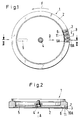
- FIG. 1 only four of a total of 50 identical cutting plates 3 made of hard metal attached to the end face 2 of a milling head 1 in the peripheral region are shown in the same division.
- the milling head 1 can be fastened by means of a central screw bolt 4 at the front end of the axis of rotation of a milling machine, not shown.
- the torque is transmitted via a recess 5 for receiving a driving wedge, not shown.
- the cutting plates 3 can be inserted into shape-matched recesses 6 with parallel edges in the end face 2 of the milling head 1 and can be fastened by means of a screw bolt 7.
- each insert 3 has a corresponding central hole 8 in its opposite side surfaces 9.
- each cutting plate (finishing cutter 10A) leading in the direction of rotation F of the milling head 1 is in the installed state on a radius of the milling head 1. Accordingly, the cutouts 6 are oriented for receiving the cutting plate in the milling head 1.
- This geometry can be realized with simple means and high precision.
- the cutting plates 3 are supported in the tangential direction on the rear, viewed in the direction of rotation F. Cut-out edge 6A of each cut-out 6. This support takes place in the radial direction by means of screw bolts 11 which are also adapted to the shape of the insert geometry.
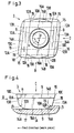
- each insert 3 has a rhombic (diamond-shaped) basic shape, the side surfaces 9 delimited by the corners (entry points 12A and exit points 12B) representing rhomboids.
- the four end faces 13A and 13B are each congruent and have a basic shape composed of two trapezoids, the end faces 13A and 13B being arranged in pairs mutually inclined to the side faces 9.
- this angle of inclination is 75 °.
- each insert which are formed jointly by the end faces 13A and 13B on the one hand and the side faces 9 on the other hand, are each provided with parallel bevels 14A and 14B inclined at 30 ° with respect to the side faces 9, the edges of adjacent end faces 13A and 13B in FIG In the region of the bevels 14A and 14B formed body edges which form the four main cutting edges 15 of each cutting plate 3.
- the short edges formed jointly by the end faces 13A and 13B and the side faces 9 of the cutting plates 3 form the finishing cutting edges 10A to 10D, which have a comparatively large radius of curvature of e.g. B. 400 mm are convexly curved.
- this curvature is exaggerated to illustrate the effect.
- This curvature is achieved in that the two side surfaces 9 are arranged with a truncated cone concentric to the hole 8 Chamfers 16 are provided.
- the apex angle of the corresponding truncated cone is comparatively large and is z. B. between 175 and 179 °.
- the inclination of the bevels 16 with respect to the side surfaces 9 is only 1 ° in each case.
- the inner boundary line of the chamfers 16 touches the size cutting edges 10A to 10D in each case in a contact point 16A which is closer to the corner (exit point) 12B than to the corner (entry point) 12A of each size cutting edge.
- the side surfaces 9 each form a rhomboid with a rhomboid angle of approximately 85 °.
- FIG. 4 shows how a main cutting edge 15, in cooperation with the finishing cutting edge 10A adjoining it at the corner (entry point) 12A, machine a workpiece 17.
- the angle of attack beta between the main cutting edge 15 and the machined workpiece surface is recognizable approximately 30 °.
- the clearance angle gamma with respect to the machined surface of the workpiece 17 is 8 °.
- the rake angle delta with respect to the axial direction A of the milling head 1 to the cutting plate 3 is 7 °.
- the contact edges of adjacent end faces 13A and 13B of the cutting plate 3, which are formed as an extension of the main cutting edges 15, can be designed as secondary cutting edges 18.
- the cutting plates 3 can be supported radially inwards relative to the milling head 1 instead of by individual screw bolts (as shown in FIG. 1) by means of a fastening ring 19 or corresponding larger ring segments which can be screwed onto the milling head 1 by means of fastening screws 20.
- the radial contact surfaces of the cutting plates 3 can be designed to be particularly precise, so that the dimensional accuracy of the screw bolts is less important than in the exemplary embodiment according to FIG. 1.
- the same cutting inserts 3 are in ten positions evenly distributed around the circumference of the boring head 21 as in FIGS 3 to 6 are provided. For the sake of simplicity, only four of these ten positions are shown in detail.
- the cutting inserts 3 are not inserted into the end face, but rather into the lateral surface 22, in such a way that the finishing cutters 10A are effective in the radial and not in the axial direction.
- a screw bolt 7 (only indicated by dash-dotted lines) is in turn used to fix each cutting plate 3.
- the exact fit and the support of each cutting plate 3 in the tangential and radial direction is accomplished by suitable cutting plate receptacles 23 as are already known per se from DE 30 36 527 A1 in terms of their basic structure. Otherwise, the same or equivalent components, angles and. Like. With the same reference numerals as in the preceding examples.
Abstract
Description
Die Erfindung betrifft einen Schneideinsatz mit den Merkmalen des Oberbegriffs von Patentanspruch 1 sowie ein Werkzeug mit den Merkmalen des Oberbegriffs von Patentanspruch 4.The invention relates to a cutting insert with the features of the preamble of
Schneideinsätze finden u. a. an Werkzeugen zur spanabhebenden Bearbeitung von zu schlichtenden Werkstückflächen wie z. B. an einem Fräskopf Anwendung, der um eine Achse rotierbar ist, und mehrere, an seiner Stirnfläche im Bereich seines äußeren Umfangs wirksame, austauschbare, Hauptschneiden aufweisende Schneidplatten sowie eine Schlichteinrichtung umfaßt, wobei die von der Stirnfläche des Fräskopfes fortweisende Seitenfläche (axiale Außenfläche) jeder Schneidplatte um einen Freiwinkel bezüglich des Fräskopfes geneigt ist. Derartige Fräsköpfe werden für die Bearbeitung insbesondere von Maschinenteilen, wie von Motoren, verwendet. Die Rotationsachse des Fräskopfes ist im wesentlichen rechtwinklig zu der bearbeiteten Werkstückoberfläche orientiert. Geringfügige Abweichungen von einer 90°-Orientierung können sich durch einen gezielt vorgesehenen Spindelsturz, Neigungsfehler der Spindel sowie die Reaktionskraft zwischen Fräskopf und Werkstück ergeben. Aufgrund dessen sowie aufgrund von Maß- und Einbautoleranzen der Schneidplatten und der Schneidplattensitze am Fräskopf weist das lediglich mit den Schneidplatten bearbeitete Werkstück eine für viele Anwendungsfälle noch zu rauhe Oberfläche auf. Deshalb sind diese Fräsköpfe mit einer Schlichteinrichtung versehen. Diese besteht bei den bekannten Fräsköpfen aus in der Regel einer einzigen sogenannten Breitschlichtplatte je Fräskopf, die z. B. in der Position einer der Schneidplatten des Fräskopfes anstelle dieser Schneidplatte eingesetzt wird. Ihre sich im wesentlichen radial erstreckende Schneidkante muß sehr genau parallel zu der bearbeiteten Werkstückoberfläche orientiert sein. Unregelmäßigkeiten in der Schneidkante, unpräziser Einbau der Breitschlichtplatte sowie wechselnde Belastungen des Fräskopfes, wie sie z. B. am Anfang und am Ende einer zu fräsenden Werkstückfläche auftreten können, schlagen sich unmittelbar als Verschlechterung der Oberflächengüte des bearbeiteten Werkstücks nieder.Cutting inserts can be found, among other things, on tools for the machining of workpiece surfaces to be finished, such as. B. on a milling head application, which is rotatable about an axis, and several, effective on its end face in the area of its outer circumference, interchangeable cutting plates having cutting edges and a finishing device, the side facing away from the end face of the milling head (axial outer surface) each insert is inclined by a clearance angle with respect to the milling head. Milling heads of this type are used for the machining, in particular of machine parts, such as motors. The axis of rotation of the milling head is oriented essentially at right angles to the machined workpiece surface. Slight deviations from a 90 ° orientation can result from a specifically designed spindle fall, inclination errors of the spindle and the reaction force between the milling head and the workpiece. Because of this and because of the dimensional and installation tolerances of the inserts and the insert seats on the milling head, the workpiece that is only machined with the inserts has a surface that is still too rough for many applications. This is why these milling heads are equipped with a finishing device. In the known milling heads, this usually consists of a single so-called wide finishing plate per milling head, which, for. B. is used in the position of one of the cutting plates of the milling head instead of this cutting plate. Its cutting edge, which extends essentially radially, must be oriented very precisely parallel to the machined workpiece surface. Irregularities in the cutting edge, imprecise installation of the wide finishing plate as well as changing loads on the milling head, such as z. B. can occur at the beginning and at the end of a workpiece surface to be milled, directly reflected as a deterioration in the surface quality of the machined workpiece.
Die Anforderungen an die Oberflächengüte spanabhebend bearbeiteter Maschinenteile u. dgl. sind zudem gewachsen. Z. B. müssen Dichtflächen bessere Oberflächen aufweisen, wenn weniger elastische und/oder asbestfreie Dichtungen verwendet werden. Ein weiteres Problem stellen zunehmend realisierte Gewichtseinsparungen dar, welche zu vergleichsweise dünnwandigen Werkstücken führen. Dünnwandige Werkstücke neigen verstärkt dazu, dem Schneiddruck beim Fräsen nachzugeben, was zu einer gewissen Welligkeit der bearbeiteten Werkstückoberfläche führen kann.The requirements for the surface quality of machined machine parts u. The like have also grown. For example, sealing surfaces must have better surfaces if less elastic and / or asbestos-free seals are used. Another problem is increasingly realized weight savings, which lead to comparatively thin-walled workpieces. Thin-walled workpieces tend to give in to the cutting pressure during milling, which can lead to a certain ripple in the machined workpiece surface.
Aus der EP-A2-0 334 129 sind Schneideinsätze für Werkzeuge zur spanabhebenden Bearbeitung bekannt, bei dem die Merkmale a), b) und c) des Patentanspruchs 1 der vorliegenden Patentanmeldung realisiert sind. Bei diesem bekannten Schneideinsatz bilden die wechselseitig paarweise sich an die Seitenflächen anschließenden Stirnflächen mit den Seitenflächen einen rechten Winkel. Dadurch wird auch zwischen den Fasen und den Stirnflächen benachbarter Wandungen (Verbindungsflächen) ein rechter Winkel gebildet. Die von den rechtwinklig sich schneidenden Flächen gebildeten Berührungskanten bilden eine erste und eine zweite Hauptschneide. Derartige Wendeschneidplatten sind lediglich für im Vergleich zu Schlichtvorgängen gröberen spanabhebenden Bearbeitungen von Werkstücken geeignet. Ein gleichzeitiges Schlichten des Werkstückes ist mit dieser Wendeschneidplatte nicht möglich.Cutting inserts for tools for machining are known from EP-A2-0 334 129, in which the features a), b) and c) of
Davon ausgehend liegt der Erfindung die Aufgabe zugrunde, einen Schneideinsatz und ein Werkzeug der eingangs genannten Art so zu gestalten, daß hohe Oberflächengüten bei vergleichsweise großen Standzeiten der Wendeschneidplatten erreicht werden. Besonders erwünscht ist auch ein möglichst weiches Schneiden des Fräskopfes, d. h. ein Schneiden mit möglichst geringem Schnittdruck.Proceeding from this, the object of the invention is to design a cutting insert and a tool of the type mentioned at the outset in such a way that high surface qualities are achieved with a comparatively long service life of the indexable inserts. It is also particularly desirable to cut the milling head as softly as possible, ie cutting with the lowest possible cutting pressure.
Zur Lösung dieser Aufgabe wird ein Schneideinsatz mit den Merkmalen des Patentanspruchs 1 sowie ein Werkzeug mit den Merkmalen des Patentanspruchs 4 vorgeschlagen.To achieve this object, a cutting insert with the features of
Derartige Schneidplatten sind vorteilhaft einsetzbar für Werkzeuge zur spanabhebenden Bearbeitung von zu schlichtenden Werkstücken, wie z. B. für Planfräsköpfe (Fräsköpfe), große und kleine Aufbohrwerkzeuge, Feinbohrwerkzeuge, Reibwerkzeuge.Such inserts can be used advantageously for tools for machining workpieces to be finished, such as. B. for face milling heads (milling heads), large and small boring tools, fine boring tools, reaming tools.
Aus der prioritätsälteren, aber nachveröffentlichten EP-A2-0 370 494 ist ein als Wendeschneidplatte bezeichneter Schneideinsatz für ein spanend arbeitendes Werkzeug, insbesondere für einen Schlichtmesserkopf, bekannt, bei dem die Merkmale a), b), c) und e) des hier vorliegenden Patentanspruchs 1 bekannt sind. Bei diesem bekanntem Schneideinsatz wird eine Krümmung der Schlichtschneidkante dadurch erzielt, daß die Stirnflächen an ihrem schneidkantennahen Rand gewölbt ausgebildet werden. Die Herstellung derart ausgebildeter Kantenwölbungen ist mit erheblichen praktischen Schwierigkeiten verbunden. Insbesondere ist es erforderlich, jede Schlichtkante durch einen gesonderten, die Wölbung realisierenden Arbeitsschritt herzustellen.From the older, but later published EP-A2-0 370 494, a cutting insert, known as an indexable insert, is known for a cutting tool, in particular for a finishing knife head, in which the features a), b), c) and e) of the present one are known Claim 1 are known. In this known cutting insert, a curvature of the finishing cutting edge is achieved in that the end faces are curved at their edge near the cutting edge. The production of edge curvatures designed in this way is associated with considerable practical difficulties. In particular, it is necessary to produce each finishing edge by means of a separate work step that realizes the curvature.
Durch die Erfindung werden u. a. folgende Vorteile erreicht:
- Jede einzelne Schneidplatte dient gleichzeitig auch als Schlichteinrichtung, weshalb relativ große Vorschubgeschwindigkeiten des Fräskopfes realisiert werden können, ohne die Standzeit des Werkzeuges bzw. der Schneidplatten und/oder die erzielte Oberflächenqualität negativ zu beeinflussen;
- die geometrische Form der Schneidplatten bleibt vergleichsweise einfach, so daß der Herstellungsaufwand nicht allzu hoch ist;
- die Schnittkräfte können vergleichsweise gering gehalten werden;
- Kantenausbrüche im Bereich des Schneidkantenaustritts vom Werkzeug sind relativ selten bzw. geringfügig;
- eine einzige Schneidplatte weist vier Hauptschneiden sowie vier zugehörige Schlichtschneiden auf;
- Toleranzabweichungen aufgrund von Toleranzen im Bereich der Schneidplatten selbst oder der Schneidplattenaufnahmen des Fräskopfes sowie Verschleißerscheinungen bzw. Fehler der Schlichtschneiden einzelner Schneidplatten wirken sich bereits deshalb nur vergleichsweise geringfügig auf die Oberflächenqualität aus, weil die Vielzahl der Schlichtschneiden je Fräskopf zu einer Egalisierung der Fehler einzelner Schlichtschneiden führt.
- Each individual insert also serves as a finishing device, which is why relatively high feed speeds of the milling head can be achieved without negatively influencing the service life of the tool or the insert and / or the surface quality achieved;
- the geometric shape of the inserts remains comparatively simple, so that the manufacturing effort is not too high;
- the cutting forces can be kept comparatively low;
- Edge chipping in the area of the cutting edge exit from the tool is relatively rare or minor;
- a single insert has four main cutting edges and four associated finishing cutting edges;
- Tolerance deviations due to tolerances in the area of the inserts themselves or the inserts of the milling head as well as signs of wear and tear or errors in the finishing cutting of individual inserts have only a comparatively minor effect on the surface quality, because the large number of finishing edges per milling head leads to an equalization of the errors of individual finishing edges .
Aufgrund der Schneidplattengeometrie ist der Keilwinkel an den Schlichtschneiden regelmäßig kleiner als 90°. Vorzugsweise liegt dieser Keilwinkel zwischen 60° und 85°, insbesondere bei 75°. Zur Erreichung derartiger Keilwinkel braucht keine der Schneidplattenoberflächen hohlgeschliffen oder in entsprechender Weise mit Spanformstufen versehen zu werden. D. h. alle Schneidplattenoberflächen können eben oder konvex gekrümmt sein, was die Herstellung der Schneidplatten vereinfacht. Diese Schneidplattengeometrie führt, insbesondere bei den insoweit bevorzugten Schneidplatten mit ebenen Oberflächen dazu, daß die Schneidplatten besonders exakt im Werkzeug, wie insbesondere in einem Fräskopf eingebettet werden können. Dies ist insbesondere im Hinblick auf die Wendemöglichkeit der Schneidplatten von Vorteil, da dann trotz der Wendemöglichkeit eine hohe Einbaupräzision und entsprechend gute Oberflächengüten erzielt werden, ohne daß das Austauschen oder Wenden der Schneidplatten besonders hohen Positionier- oder Justieraufwand zur Folge hat.Due to the insert geometry, the wedge angle on the finishing cutters is regularly less than 90 °. This wedge angle is preferably between 60 ° and 85 °, in particular 75 °. To achieve such wedge angles, none of the cutting plate surfaces need to be hollow ground or provided with chip shaping steps in a corresponding manner. That is, all insert surfaces can be flat or convex, which simplifies the manufacture of the inserts. This insert geometry, particularly in the case of the inserts with flat surfaces preferred in this regard, means that the inserts can be embedded particularly precisely in the tool, in particular in a milling head. This is particularly advantageous with regard to the ability to turn the inserts, since despite the ability to turn, a high degree of installation precision and correspondingly good surface qualities can be achieved without the need for replacing or turning the inserts requiring particularly great positioning or adjustment.
Der Ergänzungswinkel des Keilwinkels zu 90°, der bei einem bevorzugten Keilwinkel von 75° also 15° beträgt, wird vorzugsweise auf den sogenannten Freiwinkel und auf den sogenannten Spanwinkel der Schlichtschneiden aufgeteilt. Der Freiwinkel ist dabei derjenige Winkel, den die axial vom Fräskopf fortweisende Seitenfläche jeder Schneidplatte mit der bearbeiteten Werkstückoberfläche bildet. Die Schneidplatten sind also annähernd tangential bezüglich der bearbeiteten Werkstückoberfläche orientiert, wobei die den Freiwinkel bildende Schneidplattenneigung zur bearbeiteten Werkstückoberfläche nur wenige Grad, vorzugsweise etwa 2 bis 15 und insbesondere um etwa 8° beträgt. Der Freiwinkel sollte möglichst kleiner als der Ergänzungswinkel des Keilwinkels zu 90° sein, um auf einfache Weise einen geeigneten Spanwinkel der Schlichtschneiden zu erhalten. Dabei ist der Spanwinkel der Neigungswinkel der in Arbeitsrichtung weisenden Stirnfläche der Schneidplatte bezüglich der Normalen auf der bearbeiteten Werkstückoberfläche. Dieser Winkel beträgt vorteilhaft zwischen 2 und 15° und liegt vorzugsweise bei etwa 7°.The additional angle of the wedge angle to 90 °, which is 15 ° for a preferred wedge angle of 75 °, is preferably divided into the so-called clearance angle and the so-called rake angle of the finishing cutting edges. The clearance angle is the angle that the axially from Milling head forms side surface of each insert with the machined workpiece surface. The cutting inserts are therefore oriented approximately tangentially with respect to the machined workpiece surface, the inclination of the insert forming the clearance angle to the machined workpiece surface being only a few degrees, preferably approximately 2 to 15 and in particular approximately 8 °. The clearance angle should be as small as possible than the additional angle of the wedge angle of 90 ° in order to easily obtain a suitable rake angle for the finishing cutting edges. The rake angle is the angle of inclination of the end face of the cutting plate pointing in the working direction with respect to the normal on the machined workpiece surface. This angle is advantageously between 2 and 15 ° and is preferably around 7 °.
Auf die Fasen kann zwar grundsätzlich verzichtet werden, da auch ohne diese Fasen die der Erfindung zugrundeliegende Aufgabe grundsätzlich gelöst und die wesentlichen Vorteile der Erfindung erzielt werden. Derartige Fasen sind allerdings in der Vielzahl von Anwendungsfällen von großem Vorteil, insbesondere dann, wenn der Anstellwinkel, den die Hauptschneiden mit der bearbeiteten Werkstückoberfläche nicht allzu groß ist, sondern, wie erfindungsgemäß besonders bevorzugt, zwischen 20° und 60° liegt. Je geringer der Anstellwinkel ist, umso kürzer werden nämlich bei der erfindungsgemäßen Schneidplattengeometrie die Schlichtschneiden, d. h. die kurzen Trapezseiten und/oder umso länger werden die langen Trapezseiten und damit die Länge und Breite der Schneidplatten. Ohne die Fasen sind die Anstellwinkel stets gleich den Keilwinkeln, weil es sich dabei um Wechselwinkel handelt. Kleine Keilwinkel, z. B. solche von weniger als 60°, sind meistens aber unerwünscht, da sie u. a. besonders verschleißanfällig sind. Durch die erfindungsgemäßen Fasen können also unter Vermeidung vorerwähnter Nachteile die Anstellwinkel und die Keilwinkel frei und entsprechend den jeweiligen Anforderungen gewählt werden. Es ist zwar denkbar, die Anstellwinkel zwischen 15° und 70° frei zu wählen, doch haben sich Anstellwinkel zwischen 30 und 40° als besonders vorteilhaft erwiesen. Es wurde gefunden, daß besonders kleine Anstellwinkel zu besonders guten Werkstückqualitäten an den Austrittskanten der Schneiden führen. Je kleiner der Anstellwinkel ist, umso geringer ist bei sonst gleicher Schneidplattengeometrie die mit der Hauptschneide erzielbare Schnittiefe. Insofern hat sich ein Anstellwinkel von etwa 30° als besonders günstig erwiesen. Erfindungsgemäß ist es allerdings auch möglich, den außerhalb der erfindungsgemäßen Fasen verbleibenden Teil der Körperkante zwischen benachbarten Stirnflächen der Schneidplatte zu Schneidzwecken zu verwenden, und zwar als Sekundärschneide bzw. Notschneide für größere Schnittiefen.In principle, the chamfers can be dispensed with, since even without these chamfers, the object underlying the invention is fundamentally achieved and the essential advantages of the invention are achieved. Such chamfers are of great advantage in the multitude of applications, especially when the angle of attack, which the main cutting edges are not too large with the machined workpiece surface, but, as is particularly preferred according to the invention, is between 20 ° and 60 °. The smaller the angle of attack, the shorter the finishing edges in the insert geometry according to the invention, ie the short trapezoid sides and / or the longer the long trapezoid sides and thus the length and width of the inserts. Without the chamfers, the angle of attack is always the same as the wedge angle because it is an alternating angle. Small wedge angles, e.g. B. those of less than 60 °, but are mostly undesirable because they are particularly susceptible to wear are. By means of the bevels according to the invention, the angles of attack and the wedge angles can thus be chosen freely and in accordance with the respective requirements while avoiding the aforementioned disadvantages. Although it is conceivable to freely choose the angle of attack between 15 ° and 70 °, angles of attack between 30 and 40 ° have proven to be particularly advantageous. It has been found that particularly small angles of attack lead to particularly good workpiece qualities at the trailing edges of the cutting edges. The smaller the angle of attack, the smaller the depth of cut that can be achieved with the main cutting edge, with the same insert geometry. In this respect, an angle of attack of approximately 30 ° has proven to be particularly favorable. According to the invention, however, it is also possible to use the part of the body edge remaining outside the bevels according to the invention between adjacent end faces of the cutting insert for cutting purposes, specifically as a secondary cutting edge or emergency cutting edge for greater depths of cut.
Durch die konvex gekrümmten Schlichtschneiden wird erreicht, daß die Schlichtschneide nur an einem Punkt bzw. - je nach Verschleißzustand - auf einem mehr oder minder kurzen Teilstück ihrer Gesamtlänge die Solltiefe beim Schlichtvorgang erreicht. Die konvexe Krümmung der Schlichtschneide ist allerdings außerordentlich gering, so daß zwischen dem Einlaufpunkt bzw. den Auslaufpunkt und dem tiefsten Punkt der Schlichtschneide ein Höhenunterschied von in der Regel nur wenigen hundertstel Millimetern besteht. Da der Schlichtkantenverlauf in erster Näherung kreisförmig ist, führt ein Verkippen einer Schneidplatte aufgrund von Maß- und/oder Einbautoleranzen oder aufgrund eines Spindelsturzes oder aufgrund der auftretenden Schnittkräfte lediglich dazu, daß ein anderer Punkt als der ursprünglich vorgesehene Punkt entlang der Schlichtschneidenlänge der tiefste Punkt ist, wobei aber die am Werkstück wirksame Schnittiefe der Schlichtschneide immer die gleiche bleibt. Die unterschiedliche Lage des tiefsten Punktes bei verschiedenen Schneidplatten desselben Fräskopfes oder eines anderen Werkzeuges mit einer Mehrzahl von Schneideinsätzen hat aber einen nur geringfügigen Einfluß auf die letztendlich erzielte Rauhigkeit der bearbeiteten Werkstückoberfläche, weil jede der am Werkzeug, insbesondere umfangsverteilten, Schneidplatten mit einer Schlichtschneide versehen ist. Bei einem Fräskopf mit z. B. 50 Schneidplatten, deren Schlichtschneiden jeweils 7 mm lang sind, wird bei einer Fräskopfumdrehung eine Gesamtschlichtlänge von maximal 350 mm erreicht. Die Vorschubgeschwindigkeit (Relativgeschwindigkeit zwischen Fräskopf und Werkstück) kann daher in sehr großem Umfang variiert werden, ohne daß sich spürbare Veränderungen in der Oberflächengüte ergeben - vor allem dann, wenn sich diese Vorschubgeschwindigkeiten in dem gebräuchlichen Bereich von z. B. 3 bis 20 mm pro Werkzeugumdrehung bewegen. - Die Krümmung der Schlichtschneiden wird jedenfalls so gewählt, daß auch bei ungünstigster Konstellation der Einzeltoleranzen der in bezug auf die Schnittiefe tiefste Punkt der Schlichtschneiden jeweils zwischen dem Einlauf- und Auslaufpunkt der Schlichtschneide, d. h. zwischen deren Anfang und Ende liegt.The convexly curved finishing cutting edges ensure that the finishing cutting edge only reaches the desired depth during the finishing operation at one point or - depending on the state of wear - on a more or less short section of its total length. However, the convex curvature of the size cutting edge is extremely small, so that there is usually a height difference of only a few hundredths of a millimeter between the entry point or the exit point and the lowest point of the size cutting edge. Since the finishing edge course is circular in the first approximation, tilting of a cutting insert due to dimensional and / or installation tolerances or due to a spindle fall or due to the occurring cutting forces only leads to a point other than the originally intended point along the finishing edge length is the lowest point, but the effective depth of cut of the finishing cutting edge on the workpiece always remains the same. The different position of the lowest point on different inserts of the same milling head or another tool with a plurality of cutting inserts has only a minor influence on the roughness of the machined workpiece surface that is ultimately achieved, because each of the inserts on the tool, in particular distributed over the circumference, is provided with a finishing edge . In a milling head with z. B. 50 inserts, each of which has a 7 mm long finishing cutting edge, a total finishing length of maximum 350 mm is achieved with one milling head revolution. The feed rate (relative speed between milling head and workpiece) can therefore be varied to a very large extent without noticeable changes in the surface quality - especially if these feed rates are in the usual range of z.
Ein allmählich einsetzender Verschleiß der Schlichtschneiden eines Fräskopfes führt zu einer etwas verminderten Schnittiefe, die durch einen entsprechenden Axialstellungs-Ausgleich des Fräskopfes ausgeglichen werden kann. Im übrigen führt ein solcher Verschleiß dazu, daß die Schlichtschneiden nicht mehr an einem einzigen Punkt, sondern entlang einer zum bearbeiteten Werkstück exakt oberflächenparallelen Kante die größte Arbeitstiefe erreichen. Ein solcher Einschleifeffekt führt zu einer noch weiter verringerten Rauhigkeit der bearbeiteten Oberfläche.A gradual onset of wear on the finishing edges of a milling head leads to a somewhat reduced depth of cut, which can be compensated for by corresponding axial position compensation of the milling head. Moreover, such wear leads to the fact that the finishing cutting edges no longer reach the greatest working depth at a single point, but along an edge that is exactly parallel to the surface of the machined workpiece. Such a Grinding effect leads to a further reduced roughness of the machined surface.
Um zu erreichen, daß beim Bearbeitungsvorgang der tiefste Punkt der Schlichtschneiden möglichst in der Mitte der Schlichtschneide zwischen ihren beiden Endpunkten liegt, wird die Schlichtschneidenkrümmung so gewählt, daß bei noch unbelastetem Werkzeug die axiale/radiale Höhendifferenz zwischen Einlaufpunkt und tiefstem Punkt der Schlichtschneide größer, insbesondere etwa doppelt so groß wie die Höhendifferenz zwischen dem Auslaufpunkt und dem tiefsten Punkt der Schlichtschneide ist. In Verbindung mit einem Spindelsturz und/oder den Reaktionskräften auf das Werkzeug beim Schneiden/Schlichten befindet sich dann der bezüglich des Werkstücks tiefste wirksame Punkt jeder Schlichtschneide etwa in deren Mitte. Dann sollten die Höhendifferenzen zwischen dem Einlaufpunkt bzw. dem Auslaufpunkt und dem tiefsten Punkt etwa gleich sein. Auf diese Weise wird eine besonders lange Standzeit der jeweiligen Schlichtschneiden und gleichbleibend guter Oberflächenqualität des bearbeiteten Werkstücks erzielt.In order to ensure that the deepest point of the finishing cutting edge lies in the middle of the finishing cutting edge between its two end points as far as possible, the finishing cutting edge curvature is selected so that the axial / radial height difference between the entry point and the lowest point of the finishing edge is larger, especially when the tool is not yet loaded about twice the height difference between the run-out point and the lowest point of the sizing knife. In connection with a spindle fall and / or the reaction forces on the tool during cutting / finishing, the lowest effective point of each finishing cutting edge with respect to the workpiece is located approximately in the middle. Then the height differences between the entry point or the exit point and the lowest point should be approximately the same. In this way, a particularly long service life of the respective finishing cutting edges and a consistently good surface quality of the machined workpiece is achieved.
Grundsätzlich können die Ecken der Seitenflächen der Schneidplatten, d. h. die Ein- und Auslaufpunkte der beiden an einer Seitenfläche jeder Schneidplatte einander gegenüberliegende Schlichtschneiden ein beliebiges Viereck bilden. Auch derartige Schneidplatten lösen grundsätzlich bereits die der Erfindung zugrundeliegende Aufgabe. Vorzugsweise bilden diese vier Punkte aber jeweils Parallelogramme die insbesondere kongruent sind. Im einfachsten Fall handelt es sich dabei um Rechtecke. Bevorzugt sind es aber Rhomboide , d. h. Parallelogramme mit ungleichen Seiten. Im Falle rhomboider Flächen wird erreicht, daß auch hinter den Hauptschneiden ein ausreichender Freiwinkel realisierbar ist, ohne daß das radial innere Ende der zugehörigen Schlichtschneide dem radial äußeren Ende während des Schneidens/Schlichtens vorauseilt. Insbesondere wird es durch diese Schneidplattengeometrie möglich, daß der tiefste Punkt oder Bereich der Schlichtschneiden in Arbeitsrichtung der Schlichtschneide jeweils am weitesten vorn liegt. Im Allgemeinen weichen die Rhomboidwinkel etwa 1° bis 10°, und vorzugsweise um etwa 5° vom rechten Winkel ab.In principle, the corners of the side faces of the cutting inserts, that is to say the entry and exit points of the two finishing edges opposite one another on one side face of each cutting insert, can form any square. Such cutting inserts in principle already solve the problem on which the invention is based. However, these four points preferably each form parallelograms which are in particular congruent. In the simplest case, these are rectangles. However, preference is given to rhomboids, ie parallelograms with unequal sides. In the case of rhomboid surfaces, it is achieved that a sufficient clearance angle can also be achieved behind the main cutting edges without the radially inner end of the associated sizing blade leads the radially outer end during the cutting / sizing. In particular, this insert geometry makes it possible for the deepest point or region of the finishing cutting edges to be furthest forward in the working direction of the finishing cutting edge. In general, the rhomboid angles deviate from the right angle by approximately 1 ° to 10 °, and preferably by approximately 5 °.
Dadurch, daß die Seitenflächen der Schneidplatten mit einer kegelstumpfförmigen Fase versehen sind, kann dadurch in vergleichsweise einfacher Art eine geometrisch exakte und bei allen Schlichtschneiden einer Schneidplatte gleiche konvexe Krümmung der Schlichtschneiden erreicht werden - und zwar auch wenn, wie in der Regel erforderlich, die Krümmungsradien der Schlichtschneiden relativ groß sind. Auf diese Weise ist es auch mit vergleichsweise geringem Aufwand möglich, die Höhendifferenzen zwischen den Einlaufpunkten bzw. den Auslaufpunkten und den tiefsten Punkten der Schlichtschneiden unterschiedlich groß zu gestalten.Because the side surfaces of the cutting inserts are provided with a truncated cone-shaped bevel, a geometrically exact and convex curvature of the finishing cutting edges can be achieved in a comparatively simple manner for all finishing cutting edges of a cutting insert - even if, as is usually necessary, the radii of curvature the finishing edges are relatively large. In this way, it is also possible with comparatively little effort to make the height differences between the entry points or the exit points and the deepest points of the finishing cutting edges of different sizes.
Im übrigen können alle Flächen der Schneidplatten von Hause aus in sich völlig eben sein, wobei jeweils die eine Hälfte und die andere Hälfte der Flächen zueinander parallele Kanten bilden. Auch die Winkel der vier Stirnflächen und der vier die Hauptschneiden bildenden Fasen sind bezüglich der beiden zueinander vorzugsweise parallelen Seitenflächen der Schneidplatten betragsmäßig gleich groß. Auf diese Weise wird eine außerordentlich effiziente Schneidplattengeometrie mit vergleichsweise geringen Mitteln bzw. vergleichsweise einfachen Herstellungsvorgängen realisierbar, wobei eine hohe Präzision, d. h. geringe Toleranzabweichungen realisierbar sind.In addition, all surfaces of the cutting plates can be completely flat in themselves, with one half and the other half of the surfaces forming mutually parallel edges. The angles of the four end faces and the four bevels forming the main cutting edges are also of the same magnitude with respect to the two mutually parallel side surfaces of the cutting inserts. In this way, an extremely efficient insert geometry can be realized with comparatively little resources or comparatively simple manufacturing processes, with a high degree of precision, ie small tolerance deviations, being achievable.
Die vorgenannten, erfindungsgemäß zu verwendenden Bauteile und geometrischen Verhältnisse unterliegen im übrigen keinen besonderen Ausnahmebedingungen, so daß die in dem jeweiligen Anwendungsgebiet bekannten Auswahlkriterien uneingeschränkt Anwendung finden können.The aforementioned components and geometrical relationships to be used according to the invention are not subject to any special exceptional conditions, so that the selection criteria known in the respective field of application can be used without restriction.
Weitere Einzelheiten, Merkmale und Vorteile des Gegenstandes der Erfindung ergeben sich aus der nachfolgenden Beschreibung der zugehörigen Zeichnung, in der eine bevorzugte Ausführungsform eines erfindungsgemäßen Fräskopfes und einer erfindungsgemäßen Schneidplatte beispielhaft dargestellt sind. In der Zeichnung zeigen:
- Fig. 1
- einen erfindungsgemäßen Fräskopf in Stirnseiten ansicht mit vier von insgesamt 50 erfindungsgemäßen Schneidplatten;
- Fig. 2
- denselben Fräskopf im Axialschnitt, Schnitt entlang der Linie II-II gemäß Fig. 1;
- Fig. 3
- eine erfindungsgemäße Schneidplatte wie in dem Fräskopf gemäß Fig. 1 und 2 verwendete, in stark vergrößerter Seitenansicht;
- Fig. 4
- dieselbe Schneidplatte in einer Stirnansicht (Ansicht B gemäß Fig. 3) i.V.m. einem im Achsialschnitt dargestellten zu bearbeitenden Werkstück;
- Fig. 5
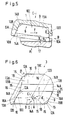
- von derselben Schneidplatte eine weitere Ansicht (Ansicht D gemäß Fig. 1 und 3) i.V.m. der Einbaugeometrie bezüglich einer Fräskopfachse nach Fig. 1 und 2 und einem im Achsialschnitt dargestellten zu bearbeitenden Werkstück;
- Fig. 6
- von derselben Schneidplatte eine perspektivische Darstellung;
- Fig. 7
- eine zu dem Fräskopf gemäß Fig. 1 alternative Ausführungsform, ausschnittsweise;
- Fig. 8
- einen Aufbohrkopf in Stirnseitenansicht (Ansicht G gemäß Fig. 9) sowie
- Fig. 9
- von demselben Aufbohrwerkzeug eine Achsial-Schnittansicht (Schnitt entlang der Linie IX-IX gemäß Fig. 8).
- Fig. 1
- a milling head according to the invention in front view with four of a total of 50 cutting tips according to the invention;
- Fig. 2
- same milling head in axial section, section along the line II-II of FIG. 1;
- Fig. 3
- a cutting plate according to the invention as used in the milling head of Figures 1 and 2, in a greatly enlarged side view.
- Fig. 4
- the same insert in an end view (view B of FIG. 3) in conjunction with a workpiece to be machined shown in axial section;
- Fig. 5
- from the same insert another view (view D according to FIGS. 1 and 3) in conjunction with the installation geometry with respect to a milling head axis according to FIGS. 1 and 2 and a workpiece to be machined shown in axial section;
- Fig. 6
- a perspective view of the same insert;
- Fig. 7
- an embodiment of the milling head according to FIG. 1, in sections;
- Fig. 8
- a boring head in front view (view G of FIG. 9) and
- Fig. 9
- an axial sectional view of the same boring tool (section along the line IX-IX according to FIG. 8).
In Fig. 1 sind von insgesamt 50 in gleicher Teilung an der Stirnfläche 2 eines Fräskopfes 1 im Peripheriebereich befestigten identischen Schneidplatten 3 aus Hartmetall lediglich vier Stück dargestellt. Der Fräskopf 1 ist mittels eines zentrischen Schraubbolzens 4 am Stirnende der Rotationsachse einer nicht dargestellten Fräsmaschine befestigbar. Die Übertragung des Drehmomentes erfolgt über eine Ausnehmung 5 zur Aufnahme eines nicht dargestellten Mitnahmekeils. Die Schneidplatten 3 sind in formangepaßte Aussparungen 6 mit parallelen Kanten in die Stirnfläche 2 des Fräskopfes 1 einsetzbar und mittels eines Schraubbolzens 7 befestigbar. Zur versenkten Aufnahme des Schraubbolzens 7 weist jede Schneidplatte 3 ein entsprechendes zentrisches Loch 8 in seinen einander gegenüberliegenden Seitenflächen 9 auf. Die in Drehrichtung F des Fräskopfes 1 vorauseilende Kante jeder Schneidplatte (Schlichtschneide 10A) befindet sich im eingebauten Zustand auf einem Radius des Fräskopfes 1. Dementsprechend sind die Aussparungen 6 zur Schneidplattenaufnahme im Fräskopf 1 orientiert. Diese Geometrie ist mit einfachen Mitteln und hoher Präzision realisierbar. Die Abstützung der Schneidplatten 3 erfolgt in tangentialer Richtung an der in Rotationsrichtung F gesehen hinteren Aussparungskante 6A jeder Aussparung 6. In radialer Richtung erfolgt diese Abstützung mittels ebenfalls an die Schneidplattengeometrie formangepaßter Schraubbolzen 11.In Fig. 1, only four of a total of 50
Wie aus Fig. 3 bis 6 ersichtlich, weist jede Schneidplatte 3 eine rhombische (rautenförmige) Grundform auf, wobei die von den Ecken (Einlaufpunkten 12A und Auslaufpunkten 12B) begrenzten Seitenflächen 9 Rhomboide darstellen.As can be seen from FIGS. 3 to 6, each
Die vier Stirnflächen 13A und 13B sind jeweils kongruent und weisen eine aus zwei Trapezen zusammengesetzte Grundform auf, wobei die Stirnflächen 13A bzw. 13B paarweise wechselseitig zu den Seitenflächen 9 geneigt angeordnet sind. Im dargestellten und insoweit bevorzugten Beispiel beträgt dieser Neigungswinkel (Keilwinkel alpha) 75°.The four end faces 13A and 13B are each congruent and have a basic shape composed of two trapezoids, the end faces 13A and 13B being arranged in pairs mutually inclined to the side faces 9. In the example shown and preferred in this respect, this angle of inclination (wedge angle alpha) is 75 °.
Die von den Stirnflächen 13A bzw. 13B einerseits und den Seitenflächen 9 andererseits gemeinsam gebildeten langen Kanten jeder Schneidplatte sind je mit unter 30° in bezug auf die Seitenflächen 9 geneigten parallelen Fasen 14A bzw. 14B versehen, wobei die von benachbarten Stirnflächen 13A und 13B im Bereich der Fasen 14A bzw. 14B gebildeten Körperkanten die vier Hauptschneiden 15 jeder Schneidplatte 3 bilden.The long edges of each insert, which are formed jointly by the end faces 13A and 13B on the one hand and the side faces 9 on the other hand, are each provided with
Die von den Stirnflächen 13A bzw. 13B und den Seitenflächen 9 der Schneidplatten 3 gemeinsam gebildeten kurzen Kanten bilden die Schlichtschneiden 10A bis 10D, welche mit vergleichsweise großem Krümmungsradius von z. B. 400 mm konvex gekrümmt sind. In Figuren 4 und 5 ist diese Krümmung übertrieben stark dargestellt, um den Effekt zu verdeutlichen. Diese Krümmung wird dadurch erzielt, daß die beiden Seitenflächen 9 mit konzentrisch zum Loch 8 angeordneten kegelstumpfförmigen Fasen 16 versehen sind. Der Spitzenwinkel des entsprechenden Kegelstumpfes ist vergleichsweise groß und beträgt z. B. zwischen 175 und 179°. Bei dem dargestellten und insoweit bevorzugten Ausführungsbeispiel beträgt er 178°, so daß die Neigung der Fasen 16 bezüglich der Seitenflächen 9 jeweils nur 1° beträgt. Die innere Begrenzungslinie der Fasen 16 tangiert die Schlichtschneiden 10A bis 10D jeweils in einem Berührungspunkt 16A, der näher an der Ecke (Auslaufpunkt) 12B als an der Ecke (Einlaufpunkt) 12A jeder Schlichtschneide liegt.The short edges formed jointly by the end faces 13A and 13B and the side faces 9 of the
Die Seitenflächen 9 bilden in ihrer Grundform jeweils einen Rhomboid mit einem Rhomboidwinkel etwa von 85°.In their basic form, the side surfaces 9 each form a rhomboid with a rhomboid angle of approximately 85 °.
Aus Fig. 4 ist ersichtlich, in welcher Weise eine Hauptschneide 15 im Zusammenwirken mit der sich an sie an der Ecke (Einlaufpunkt) 12A anschließenden Schlichtschneide 10A ein Werkstück 17 spanend bearbeiten. Erkennbar beträgt der Anstellwinkel Beta zwischen Hauptschneide 15 und bearbeiteter Werkstückoberfläche etwa 30°.4 shows how a
Aus Fig. 5 ergibt sich eine radiale Ansicht einer Schneidplatte (von innen nach außen betrachtet). Der Freiwinkel Gamma in bezug auf die bearbeitete Oberfläche des Werkstücks 17 beträgt 8°. Der sich bezüglich der Achsrichtung A des Fräskopfes 1 zur Schneidplatte 3 ergebende Spanwinkel Delta beträgt 7°.5 shows a radial view of a cutting insert (viewed from the inside out). The clearance angle gamma with respect to the machined surface of the
Die in Verlängerung der Hauptschneiden 15 ausgebildeten Berührungskanten benachbarter Stirnflächen 13A und 13B der Schneidplatte 3 können als Sekundärschneiden 18 ausgebildet sein.The contact edges of adjacent end faces 13A and 13B of the cutting
Es versteht sich, daß jede Schneidplatte 3 möglichst vollflächig an den Wandungen der Aussparungen 6, 6A des Fräskopfes 1 anliegen. Dies ist in Fig. 5 schematisch angedeutet.It is understood that each
Gemäß Fig. 7 kann die Abstützung der Schneidplatten 3 nach radial innen gegenüber dem Fräskopf 1 anstatt durch einzelne Schraubbolzen (wie in Fig. 1 dargestellt) durch einen Befestigungsring 19 oder entsprechende größere Ringsegmente vorgenommen werden, die durch Befestigungsschrauben 20 am Fräskopf 1 festschraubbar sind. Hierdurch können die radialen Anlagenflächen der Schneidplatten 3 besonders maßgenau ausgestaltet werden, so daß es auf die Maßhaltigkeit der Schraubbolzen weniger ankommt, als beim Ausführungsbeispiel gemäß Fig. 1.According to FIG. 7, the cutting
Bei dem in den Fig. 8 und 9 dargestellten Werkzeug, nämlich einem Aufbohrkopf, mit dem das Aufbohren und Schlichten einer Zylinderwand in einem einzigen Arbeitsgang erfolgt, sind in zehn am Umfang des Aufbohrkopfes 21 gleichmäßig verteilten Positionen die gleichen Schneideinsätze 3, wie in den Fig. 3 bis 6 dargestellt, vorgesehen. Der Einfachheit halber sind nur vier dieser zehn Positionen detailliert dargestellt. Im Gegensatz zu dem Ausführungsbeispiel nach Fig. 1, 2 und 7 sind die Schneidplatten 3 nicht in die Stirnfläche, sondern in die Mantelfläche 22 eingesetzt, und zwar derart, daß die Schlichtschneiden 10A in radialer und nicht in axialer Richtung wirksam werden.In the tool shown in FIGS. 8 and 9, namely a boring head, with which the boring and finishing of a cylinder wall is carried out in a single operation, the same cutting inserts 3 are in ten positions evenly distributed around the circumference of the
Zur Fixierung jeder Schneidplatte 3 wird wiederum ein Schraubbolzen 7 (nur strichpunktiert angedeutet) verwendet. Der exakte Sitz und die Abstützung jeder Schneidplatte 3 in tangentialer und radialer Richtung (beides einstellbar), wird durch geeignete Schneidplattenaufnahmen 23 bewerkstelligt wie sie vom grundsätzlichen Aufbau her bereits aus der DE 30 36 527 A1 an sich bekannt sind. Im übrigen sind gleiche bzw. gleichwirkende Bauteile, Winkel u. dgl. mit denselben Bezugsziffern wie in den vorangehenden Beispielen bezeichnet.A screw bolt 7 (only indicated by dash-dotted lines) is in turn used to fix each cutting
- 11
- WerkzeugTool
- 22nd
- StirnflächeFace
- 33rd
- SchneidplatteInsert
- 44th
- SchraubbolzenBolts
- 55
- AusnehmungRecess
- 66
- AussparungRecess
- 6A6A
- AussparungskanteRecess edge
- 77
- SchraubbolzenBolts
- 88th
- Lochhole
- 99
- SeitenflächeSide surface
- 10A bis 10D10A to 10D
- SchlichtschneidenFinishing cutting
- 1111
- SchraubbolzenBolts
- 12A12A
- Ecke (Einlaufpunkt)Corner (entry point)
- 12B12B
- Ecke (Auslaufpunkt)Corner (exit point)
- 13A13A
- StirnflächeFace
- 13B13B
- StirnflächeFace
- 14A14A
- Fasechamfer
- 14B14B
- Fasechamfer
- 1515
- HauptschneideMain cutting edge
- 1616
- Fasechamfer
- 16A16A
- BerührungspunktPoint of contact
- 1717th
- Werkstückworkpiece
- 1818th
- SekundärschneideSecondary cutting edge
- 1919th
- BefestigungsringMounting ring
- 2020th
- BefestigungsschraubenMounting screws
- 2121
- AufbohrkopfBoring head
- 2222
- MantelflächeLateral surface
- 2323
- SchneidplattenaufnahmeInsert holder
- AA
- Ansicht/AchsrichtungView / axis direction
- BB
- Ansichtview
- CC.
- Ansichtview
- DD
- Ansichtview
- FF
- RotationsrichtungDirection of rotation
- GG
- Ansichtview
- αα
- KeilwinkelWedge angle
- ββ
- AnstellwinkelAngle of attack
- γγ
- FreiwinkelClearance angle
- δδ
- SpanwinkelRake angle
- εε
- RhomboidwinkelRhomboid angle
Claims (4)
- A cutting tool tip for tools for chip-removing machining of workpiece surfaces to be finished,a) with two staggered oblong side surfaces (9) parallel to and opposite each other and each having four corners (12A, 12B),b) with four multiple-part connecting surfaces connecting the side surfaces (9) and each comprising a chamfer (14A, 14 B), adjacent to one of the respective longer edges of the side surfaces (9), and each comprising an end surface (13A, 13B) adjacent to one of the respective shorter edges of the side surfaces (9) on the one hand and to the chamfer (14A, 14B) associated with the same connecting surface on the other,c) where the connecting surfaces are arranged in pairs alternately inclined with respect to the side surfaces (9),d) where edges formed respectively by a chamfer (14A, 14B) of a connecting surface with the end surface (13B, 13A) of an adjacent connecting surface form primary cutting edges (15),e) where the short edges formed jointly by the end and side surfaces (13A and 9 and/or 13B and 9) of the cutting tool (3) are curved in a convex manner and form the finishing cutting edges (10A to 10D) andf) where frustoconical chamfers (16) are provided on the side surfaces (9) of the cutting tool tips(3) for forming the convex curves of the finishing cutting edges(10A to 10D).
- A cutting tool tip according to Claim 1, characterised in that the corners (12A, 12B) of the side surfaces (9) of the cutting tool tips (3) form a parallelogram.
- A cutting tool tip according to Claim 2, characterised in that the parallelograms are rhomboids.
- A tool for chip-removing machining of workpiece surfaces to be finished, which is rotatable about an axis (axial direction A) and has a plurality of operative and interchangeable cutting tool tips (3) having primary cutting edges (15) on its end surface (2) in the region of its outer periphery, and also with a finishing device, wherein the side surface (9) of each cutting tool tip (3) points away from the end surface (2) or from the outer surface (22) of the tool (1, 21) and is set at an angle of clearance (γ) relative to the surface of the workpiece (17) to be machined, characterised in that the cutting tool tips are formed according to one of Claims 1 to 3.
Applications Claiming Priority (3)
| Application Number | Priority Date | Filing Date | Title |
|---|---|---|---|
| DE4013717 | 1990-04-28 | ||
| DE4013717A DE4013717A1 (en) | 1989-10-07 | 1990-04-28 | Inserted tooth face mill for high quality finish - has cutter inserts in form of rhombus with four main and four finishing cutting edges |
| PCT/EP1991/000825 WO1991017014A1 (en) | 1990-04-28 | 1991-04-29 | Cutting insert for tools |
Publications (2)
| Publication Number | Publication Date |
|---|---|
| EP0485546A1 EP0485546A1 (en) | 1992-05-20 |
| EP0485546B1 true EP0485546B1 (en) | 1995-02-15 |
Family
ID=6405351
Family Applications (1)
| Application Number | Title | Priority Date | Filing Date |
|---|---|---|---|
| EP91908607A Expired - Lifetime EP0485546B1 (en) | 1990-04-28 | 1991-04-29 | Cutting insert for tools |
Country Status (10)
| Country | Link |
|---|---|
| US (1) | US5256009A (en) |
| EP (1) | EP0485546B1 (en) |
| JP (1) | JPH04506777A (en) |
| KR (1) | KR920702645A (en) |
| AT (1) | ATE118387T1 (en) |
| AU (1) | AU7778791A (en) |
| BR (1) | BR9105722A (en) |
| DE (1) | DE59104593D1 (en) |
| ES (1) | ES2071308T3 (en) |
| WO (1) | WO1991017014A1 (en) |
Families Citing this family (11)
| Publication number | Priority date | Publication date | Assignee | Title |
|---|---|---|---|---|
| US5957629A (en) * | 1994-01-14 | 1999-09-28 | Sandvik Ab | Fine milling cutting insert |
| SE509224C2 (en) * | 1994-05-19 | 1998-12-21 | Sandvik Ab | Inserts |
| USD381026S (en) * | 1994-08-18 | 1997-07-15 | Sandvik Ab | Milling cutter insert for fine milling |
| JP4465809B2 (en) | 1999-07-09 | 2010-05-26 | 三菱マテリアル株式会社 | Throwaway tip |
| US6769844B2 (en) | 2001-01-10 | 2004-08-03 | Kennametal Inc. | Cutting insert and method of making the same |
| US7168512B2 (en) * | 2001-09-06 | 2007-01-30 | Kennametal Inc. | Cutting insert and milling cutter with such a cutting insert |
| WO2003022496A1 (en) * | 2001-09-06 | 2003-03-20 | Kennametal Inc. | Cutting insert and milling cutter comprising such a cutting insert |
| DE102005025815A1 (en) * | 2005-06-02 | 2006-12-07 | Kennametal Widia Produktions Gmbh & Co. Kg | Cutting insert, in particular for crankshaft machining |
| JP4231496B2 (en) * | 2005-08-01 | 2009-02-25 | 住友電工ハードメタル株式会社 | Throwaway tip |
| AT508492A1 (en) * | 2009-07-08 | 2011-01-15 | Boehlerit Gmbh & Co Kg | END MILLS |
| DE102019123912A1 (en) | 2019-09-05 | 2021-03-11 | Kennametal Inc. | Cutting insert and cutting tool |
Family Cites Families (10)
| Publication number | Priority date | Publication date | Assignee | Title |
|---|---|---|---|---|
| US3541655A (en) * | 1967-12-29 | 1970-11-24 | Carmet Co | Indexable and reversible cutting inserts |
| US4294565A (en) * | 1980-03-06 | 1981-10-13 | General Electric Company | Indexable finishing insert for a milling cutter |
| JPH0620657B2 (en) * | 1985-10-11 | 1994-03-23 | 株式会社東芝 | Front milling cutter |
| JPH0715686Y2 (en) * | 1987-03-04 | 1995-04-12 | 三菱マテリアル株式会社 | Ball end mill |
| US5035546A (en) * | 1987-10-01 | 1991-07-30 | Gte Valenite Corporation | Radiused on-edge indexable cutting insert |
| US5114282A (en) * | 1988-03-21 | 1992-05-19 | Gte Valenite Corporation | Indexable insert for roughing and finishing |
| US5028175A (en) * | 1988-03-21 | 1991-07-02 | Gte Valenite Corporation | Indexable insert for roughing and finishing |
| DE3839804A1 (en) * | 1988-11-25 | 1990-05-31 | Widia Heinlein Gmbh | INSERT INSERT |
| US4840518A (en) * | 1988-12-27 | 1989-06-20 | Gte Valenite Corporation | Cutting insert |
| IL93883A (en) * | 1989-04-12 | 1993-02-21 | Iscar Ltd | Cutting insert for a milling cutting tool |
-
1991
- 1991-04-29 JP JP3508174A patent/JPH04506777A/en active Pending
- 1991-04-29 ES ES91908607T patent/ES2071308T3/en not_active Expired - Lifetime
- 1991-04-29 AT AT91908607T patent/ATE118387T1/en active
- 1991-04-29 US US07/778,840 patent/US5256009A/en not_active Expired - Lifetime
- 1991-04-29 EP EP91908607A patent/EP0485546B1/en not_active Expired - Lifetime
- 1991-04-29 BR BR919105722A patent/BR9105722A/en not_active IP Right Cessation
- 1991-04-29 WO PCT/EP1991/000825 patent/WO1991017014A1/en active IP Right Grant
- 1991-04-29 KR KR1019910701985A patent/KR920702645A/en not_active Application Discontinuation
- 1991-04-29 DE DE59104593T patent/DE59104593D1/en not_active Expired - Lifetime
- 1991-04-29 AU AU77787/91A patent/AU7778791A/en not_active Abandoned
Also Published As
| Publication number | Publication date |
|---|---|
| AU7778791A (en) | 1991-11-27 |
| DE59104593D1 (en) | 1995-03-23 |
| KR920702645A (en) | 1992-10-06 |
| US5256009A (en) | 1993-10-26 |
| WO1991017014A1 (en) | 1991-11-14 |
| ES2071308T3 (en) | 1995-06-16 |
| BR9105722A (en) | 1992-08-04 |
| JPH04506777A (en) | 1992-11-26 |
| EP0485546A1 (en) | 1992-05-20 |
| ATE118387T1 (en) | 1995-03-15 |
Similar Documents
| Publication | Publication Date | Title |
|---|---|---|
| EP2403673B2 (en) | End mill cutter | |
| DE2660167C2 (en) | Milling tool with a circular cylindrical tool body | |
| EP1184116B1 (en) | Slot drill | |
| EP0830228B1 (en) | Metal-cutting process for machining cylindrical contours, device for carrying out the process and cutting insert therefor | |
| EP1907158B1 (en) | Cutting insert, tool and method of machining a workpiece | |
| EP1511590B1 (en) | Milling cutter having a wiper radius | |
| EP2484471B1 (en) | Machining tool | |
| DE3831535A1 (en) | HEAD MILLING | |
| DE102015112417B4 (en) | Rotary cutting tool with regrindable cutting inserts | |
| AT410188B (en) | CUTTING TOOL AND TABLE CUTTING PLATE | |
| EP0485546B1 (en) | Cutting insert for tools | |
| DE10052963A1 (en) | Blade tip exchange type cutting tool for carving processing of metal die, has curvature radius of end cutting edge made larger than diameter of inscribing circle or length of long side of throw away tip | |
| WO2008052503A1 (en) | Finishing/roughing mill | |
| EP1283083B1 (en) | Milling cutting insert | |
| EP0537476B1 (en) | Milling head | |
| EP0912283B1 (en) | High-speed milling | |
| DE19517311A1 (en) | Insert arrangement for drilling tool | |
| DE102005058536B4 (en) | Cutting tool system, in particular for splining bevel gears in the single-part method | |
| DE3909643C2 (en) | Multi-cutting tool head for machining preliminary and fine machining with a circular cutting movement | |
| EP1436111A1 (en) | Cutting insert and milling cutter comprising such a cutting insert | |
| EP3892407A1 (en) | Tool for the machining of non-metallic materials | |
| DE10144735B4 (en) | Cutting inserts and rotary milling cutters with interchangeable cutting inserts | |
| DE10333621A1 (en) | Cutter head for attachment to cutter wheel has flat front surface with aperture for fastening screw and rounded convex regions with sharp cutting edges formed on slightly tapered side contours | |
| DE4013717A1 (en) | Inserted tooth face mill for high quality finish - has cutter inserts in form of rhombus with four main and four finishing cutting edges | |
| EP3630400A1 (en) | Single-lip deep-hole drill with a chamfered rake face |
Legal Events
| Date | Code | Title | Description |
|---|---|---|---|
| PUAI | Public reference made under article 153(3) epc to a published international application that has entered the european phase |
Free format text: ORIGINAL CODE: 0009012 |
|
| 17P | Request for examination filed |
Effective date: 19911203 |
|
| AK | Designated contracting states |
Kind code of ref document: A1 Designated state(s): AT BE DE ES FR GB IT NL SE |
|
| 17Q | First examination report despatched |
Effective date: 19930701 |
|
| GRAA | (expected) grant |
Free format text: ORIGINAL CODE: 0009210 |
|
| AK | Designated contracting states |
Kind code of ref document: B1 Designated state(s): AT BE DE ES FR GB IT NL SE |
|
| REF | Corresponds to: |
Ref document number: 118387 Country of ref document: AT Date of ref document: 19950315 Kind code of ref document: T |
|
| REF | Corresponds to: |
Ref document number: 59104593 Country of ref document: DE Date of ref document: 19950323 |
|
| ITF | It: translation for a ep patent filed |
Owner name: MODIANO & ASSOCIATI S.R.L. |
|
| ET | Fr: translation filed | ||
| REG | Reference to a national code |
Ref country code: ES Ref legal event code: FG2A Ref document number: 2071308 Country of ref document: ES Kind code of ref document: T3 |
|
| GBT | Gb: translation of ep patent filed (gb section 77(6)(a)/1977) |
Effective date: 19950605 |
|
| PLBE | No opposition filed within time limit |
Free format text: ORIGINAL CODE: 0009261 |
|
| STAA | Information on the status of an ep patent application or granted ep patent |
Free format text: STATUS: NO OPPOSITION FILED WITHIN TIME LIMIT |
|
| 26N | No opposition filed | ||
| PGFP | Annual fee paid to national office [announced via postgrant information from national office to epo] |
Ref country code: AT Payment date: 19980415 Year of fee payment: 8 |
|
| PGFP | Annual fee paid to national office [announced via postgrant information from national office to epo] |
Ref country code: SE Payment date: 19980416 Year of fee payment: 8 |
|
| PGFP | Annual fee paid to national office [announced via postgrant information from national office to epo] |
Ref country code: ES Payment date: 19980428 Year of fee payment: 8 Ref country code: NL Payment date: 19980428 Year of fee payment: 8 |
|
| PGFP | Annual fee paid to national office [announced via postgrant information from national office to epo] |
Ref country code: BE Payment date: 19980609 Year of fee payment: 8 |
|
| PG25 | Lapsed in a contracting state [announced via postgrant information from national office to epo] |
Ref country code: AT Free format text: LAPSE BECAUSE OF NON-PAYMENT OF DUE FEES Effective date: 19990429 |
|
| PG25 | Lapsed in a contracting state [announced via postgrant information from national office to epo] |
Ref country code: SE Free format text: LAPSE BECAUSE OF NON-PAYMENT OF DUE FEES Effective date: 19990430 Ref country code: BE Free format text: LAPSE BECAUSE OF NON-PAYMENT OF DUE FEES Effective date: 19990430 Ref country code: ES Free format text: LAPSE BECAUSE OF NON-PAYMENT OF DUE FEES Effective date: 19990430 |
|
| BERE | Be: lapsed |
Owner name: SANDVIK A.B. Effective date: 19990430 |
|
| PG25 | Lapsed in a contracting state [announced via postgrant information from national office to epo] |
Ref country code: NL Free format text: LAPSE BECAUSE OF NON-PAYMENT OF DUE FEES Effective date: 19991101 |
|
| NLV4 | Nl: lapsed or anulled due to non-payment of the annual fee |
Effective date: 19991101 |
|
| EUG | Se: european patent has lapsed |
Ref document number: 91908607.4 |
|
| REG | Reference to a national code |
Ref country code: ES Ref legal event code: FD2A Effective date: 20010503 |
|
| REG | Reference to a national code |
Ref country code: GB Ref legal event code: IF02 |
|
| PG25 | Lapsed in a contracting state [announced via postgrant information from national office to epo] |
Ref country code: IT Free format text: LAPSE BECAUSE OF NON-PAYMENT OF DUE FEES;WARNING: LAPSES OF ITALIAN PATENTS WITH EFFECTIVE DATE BEFORE 2007 MAY HAVE OCCURRED AT ANY TIME BEFORE 2007. THE CORRECT EFFECTIVE DATE MAY BE DIFFERENT FROM THE ONE RECORDED. Effective date: 20050429 |
|
| REG | Reference to a national code |
Ref country code: GB Ref legal event code: 732E |
|
| REG | Reference to a national code |
Ref country code: GB Ref legal event code: 732E |
|
| REG | Reference to a national code |
Ref country code: FR Ref legal event code: TP |
|
| REG | Reference to a national code |
Ref country code: FR Ref legal event code: TP |
|
| PGFP | Annual fee paid to national office [announced via postgrant information from national office to epo] |
Ref country code: GB Payment date: 20100325 Year of fee payment: 20 |
|
| PGFP | Annual fee paid to national office [announced via postgrant information from national office to epo] |
Ref country code: FR Payment date: 20100521 Year of fee payment: 20 |
|
| PGFP | Annual fee paid to national office [announced via postgrant information from national office to epo] |
Ref country code: DE Payment date: 20100430 Year of fee payment: 20 |
|
| REG | Reference to a national code |
Ref country code: DE Ref legal event code: R071 Ref document number: 59104593 Country of ref document: DE |
|
| REG | Reference to a national code |
Ref country code: GB Ref legal event code: PE20 Expiry date: 20110428 |
|
| PG25 | Lapsed in a contracting state [announced via postgrant information from national office to epo] |
Ref country code: GB Free format text: LAPSE BECAUSE OF EXPIRATION OF PROTECTION Effective date: 20110428 |
|
| PG25 | Lapsed in a contracting state [announced via postgrant information from national office to epo] |
Ref country code: DE Free format text: LAPSE BECAUSE OF EXPIRATION OF PROTECTION Effective date: 20110429 |