EP2403673B2 - End mill cutter - Google Patents
End mill cutter Download PDFInfo
- Publication number
- EP2403673B2 EP2403673B2 EP10713554.3A EP10713554A EP2403673B2 EP 2403673 B2 EP2403673 B2 EP 2403673B2 EP 10713554 A EP10713554 A EP 10713554A EP 2403673 B2 EP2403673 B2 EP 2403673B2
- Authority
- EP
- European Patent Office
- Prior art keywords
- end mill
- chip
- mill cutter
- cutter according
- cutting edges
- Prior art date
- Legal status (The legal status is an assumption and is not a legal conclusion. Google has not performed a legal analysis and makes no representation as to the accuracy of the status listed.)
- Active
Links
Images


Classifications
-
- B—PERFORMING OPERATIONS; TRANSPORTING
- B23—MACHINE TOOLS; METAL-WORKING NOT OTHERWISE PROVIDED FOR
- B23C—MILLING
- B23C5/00—Milling-cutters
- B23C5/02—Milling-cutters characterised by the shape of the cutter
- B23C5/10—Shank-type cutters, i.e. with an integral shaft
-
- B—PERFORMING OPERATIONS; TRANSPORTING
- B23—MACHINE TOOLS; METAL-WORKING NOT OTHERWISE PROVIDED FOR
- B23C—MILLING
- B23C5/00—Milling-cutters
- B23C5/003—Milling-cutters with vibration suppressing means
-
- B—PERFORMING OPERATIONS; TRANSPORTING
- B23—MACHINE TOOLS; METAL-WORKING NOT OTHERWISE PROVIDED FOR
- B23C—MILLING
- B23C2210/00—Details of milling cutters
- B23C2210/04—Angles
- B23C2210/0485—Helix angles
-
- B—PERFORMING OPERATIONS; TRANSPORTING
- B23—MACHINE TOOLS; METAL-WORKING NOT OTHERWISE PROVIDED FOR
- B23C—MILLING
- B23C2210/00—Details of milling cutters
- B23C2210/04—Angles
- B23C2210/0485—Helix angles
- B23C2210/0492—Helix angles different
-
- B—PERFORMING OPERATIONS; TRANSPORTING
- B23—MACHINE TOOLS; METAL-WORKING NOT OTHERWISE PROVIDED FOR
- B23C—MILLING
- B23C2210/00—Details of milling cutters
- B23C2210/08—Side or top views of the cutting edge
- B23C2210/086—Discontinuous or interrupted cutting edges
-
- B—PERFORMING OPERATIONS; TRANSPORTING
- B23—MACHINE TOOLS; METAL-WORKING NOT OTHERWISE PROVIDED FOR
- B23C—MILLING
- B23C2210/00—Details of milling cutters
- B23C2210/08—Side or top views of the cutting edge
- B23C2210/088—Cutting edges with a wave form
-
- B—PERFORMING OPERATIONS; TRANSPORTING
- B23—MACHINE TOOLS; METAL-WORKING NOT OTHERWISE PROVIDED FOR
- B23C—MILLING
- B23C2210/00—Details of milling cutters
- B23C2210/28—Arrangement of teeth
- B23C2210/282—Unequal angles between the cutting edges, i.e. cutting edges unequally spaced in the circumferential direction
-
- B—PERFORMING OPERATIONS; TRANSPORTING
- B23—MACHINE TOOLS; METAL-WORKING NOT OTHERWISE PROVIDED FOR
- B23C—MILLING
- B23C2210/00—Details of milling cutters
- B23C2210/48—Chip breakers
- B23C2210/486—Chip breaking grooves or depressions
-
- B—PERFORMING OPERATIONS; TRANSPORTING
- B23—MACHINE TOOLS; METAL-WORKING NOT OTHERWISE PROVIDED FOR
- B23C—MILLING
- B23C2220/00—Details of milling processes
- B23C2220/60—Roughing
-
- B—PERFORMING OPERATIONS; TRANSPORTING
- B23—MACHINE TOOLS; METAL-WORKING NOT OTHERWISE PROVIDED FOR
- B23C—MILLING
- B23C2250/00—Compensating adverse effects during milling
- B23C2250/16—Damping vibrations
-
- Y—GENERAL TAGGING OF NEW TECHNOLOGICAL DEVELOPMENTS; GENERAL TAGGING OF CROSS-SECTIONAL TECHNOLOGIES SPANNING OVER SEVERAL SECTIONS OF THE IPC; TECHNICAL SUBJECTS COVERED BY FORMER USPC CROSS-REFERENCE ART COLLECTIONS [XRACs] AND DIGESTS
- Y10—TECHNICAL SUBJECTS COVERED BY FORMER USPC
- Y10T—TECHNICAL SUBJECTS COVERED BY FORMER US CLASSIFICATION
- Y10T407/00—Cutters, for shaping
- Y10T407/19—Rotary cutting tool
- Y10T407/1946—Face or end mill
- Y10T407/1948—Face or end mill with cutting edge entirely across end of tool [e.g., router bit, end mill, etc.]
-
- Y—GENERAL TAGGING OF NEW TECHNOLOGICAL DEVELOPMENTS; GENERAL TAGGING OF CROSS-SECTIONAL TECHNOLOGIES SPANNING OVER SEVERAL SECTIONS OF THE IPC; TECHNICAL SUBJECTS COVERED BY FORMER USPC CROSS-REFERENCE ART COLLECTIONS [XRACs] AND DIGESTS
- Y10—TECHNICAL SUBJECTS COVERED BY FORMER USPC
- Y10T—TECHNICAL SUBJECTS COVERED BY FORMER US CLASSIFICATION
- Y10T407/00—Cutters, for shaping
- Y10T407/19—Rotary cutting tool
- Y10T407/1952—Having peripherally spaced teeth
- Y10T407/1956—Circumferentially staggered
- Y10T407/1958—Plural teeth spaced about a helix
-
- Y—GENERAL TAGGING OF NEW TECHNOLOGICAL DEVELOPMENTS; GENERAL TAGGING OF CROSS-SECTIONAL TECHNOLOGIES SPANNING OVER SEVERAL SECTIONS OF THE IPC; TECHNICAL SUBJECTS COVERED BY FORMER USPC CROSS-REFERENCE ART COLLECTIONS [XRACs] AND DIGESTS
- Y10—TECHNICAL SUBJECTS COVERED BY FORMER USPC
- Y10T—TECHNICAL SUBJECTS COVERED BY FORMER US CLASSIFICATION
- Y10T409/00—Gear cutting, milling, or planing
- Y10T409/30—Milling
- Y10T409/303752—Process
Definitions
- the invention relates to an end mill according to the preamble of patent claim 1.
- an end mill is shown in FIG U.S. 4,770,567 known.
- Such milling cutters have as a common feature a shank as a clamping part, which is inserted into the tool holder.
- Such milling cutters are used, for example, as slot milling cutters or die milling cutters with a flat or round face.
- Such milling cutters are also characterized in that they have a plurality of helically extending circumferential cutting edges in the area of their cutting section on the milling webs separated from one another by flutes, each of which is designed with a roughing profile in such a way that the circumferential cutting edges receive chip breaker grooves, the chip breaker grooves of in the circumferential direction adjacent milling webs are axially offset from one another.
- Such roughing profiles are standardized, for example, in DIN 1836 in the versions "round” and “flat”, whereby with regard to the structure of the profile, if necessary with regard to the slope with which the chip breaker grooves are made in the milling webs, between "extra-coarse", A distinction is made between “coarse” and “fine”.
- the profile structure such as the gradients of the recesses forming the chip breaker grooves, are material-dependent, with the gradient being selected to be finer as the hardness of the material to be machined increases.
- the pitch can also be dependent on the tool diameter, in which case the rule is that the smaller the diameter of the end mill, the finer the pitch.
- the interrupted, ie profiled, profile of the tool cutting edge enables the roughing cutter to break the chip more quickly.
- the roughing cutter is not suitable for producing a uniform surface with a high surface quality. Due to the short-chipping behavior of the removed material, however, the result is a significantly better one Chip evacuation than with the finishing cutter. Due to the high metal removal rate, roughing milling tools of the type described at the beginning are also ideally suited for operations in which the aim is to remove material as effectively and quickly as possible with a finishing milling tool up to a finishing dimension of, for example, 0.5 mm. In addition, the cutting pressure and the power consumption of the machine are lower when working with such roughing cutters, and the tool can drive a high cutting depth and cutting width.
- finishing cutters i.e. end mills with smooth cutting edges
- finishing cutters are able to produce a workpiece surface with high dimensional accuracy and quality, i.e. smoothness, which is due to the regularity of the tool cutting edge, the high speed with simultaneously low feed speed of the milling tool and the in usually results in a low chip volume due to the low finishing allowance, which can be between 0.1 and 1.0 mm depending on the area of application.
- finishing cutters are used with larger infeed depths or infeed widths, on the one hand chip evacuation problems occur due to the longer and larger chips, and on the other hand the power consumption and the cutting pressure increase disproportionately.
- the invention is therefore based on the object of developing an end mill of the type described at the outset, in particular according to the preamble of claim 1, in such a way that, while ensuring higher Tool life, with low machine power consumption and reduced cutting pressure, particularly suitable for providing a high material removal rate and at the same time machining the workpiece with good surface quality.
- the measure known from the field of finishing cutters of varying the helix angle of the circumferential cutting edges, which are circumferentially spaced from one another is advantageously combined with a new geometry of the chip breaker grooves, resulting in a milling tool which, in terms of chip formation, the power consumption of the machine, the cutting pressure, the chip evacuation, the achievable cutting width and the surface quality only combine the advantages of conventional roughing and finishing cutters.
- the end mill according to the invention still produces short chips and therefore has a low power consumption. Furthermore, the cutting pressure is low and the short chips result in good chip evacuation. Due to the flattened roughing profile in connection with the measure that at least two circumferential cutting edges have different helix angles, the tendency of the milling cutter to vibrate, which is normally pre-marked by the roughing profile, is considerably reduced, so that over the preferably essentially flattened areas of the roughing profile or with a roughing-finishing profile according to DIN 1836 Very high quality surfaces with a good tool life can be produced, since the rounded edges of the chip breaker grooves in the transition to the preferably essentially flattened section of the roughing profile ensure that a soft cut is ensured over the life of the tool with minimized impact stress on the circumferential cutting edge. In this way, the milling tool according to the invention is particularly suitable for working with large cutting widths and depths, for example in slot milling, the chip shape remaining similarly favorable as in pure rough milling.
- the value of the helix angle differences in the range between 1 and 6 ° is selected as a function of the material to be machined and / or the material of the end mill and / or its coating.
- Tests have shown that it is advantageous to adjust the flank radius over which the chip splitting groove merges into the flattened section of the roughing profile in the range between 0.1 and 1.0 mm, particularly preferably between 0.1 and 0.5 mm in order to maintain the required service life with the given surface quality.
- the chip breaker grooves can be manufactured using a profile grinding wheel.
- the chip breaker grooves are positioned in relation to a plane of the end mill that is perpendicular to a longitudinal axis of the end mill, whereby it is possible to influence the chip formation in an advantageous manner.
- the chip breaker grooves can each follow the course of a helix in sections, the pitch of which corresponds, for example, to the pitch of the roughing profile or to an integral multiple of the pitch.
- chip breaker grooves parallel to a plane of the end mill that is perpendicular to a longitudinal axis of the end mill.
- flank radius facing the cutter shank in the chip splitting groove is smaller than the other flank radius, in particular in the event that the flank radius facing the cutter shank takes part in chip formation first.
- the machining performance, surface quality and tool life can be further optimized by choosing the material for the end mill. It has been found that the design according to the invention unfolds its particular advantages when the tool is made of hard material as a whole or at least in the area of the cutting section, with solid carbide, for example, but also a cermet material being able to be used as hard material.
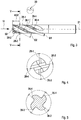
- Reference numeral 20 denotes an end mill which has a cutting section 22 and a clamping shank 24.
- the milling cutter axis is denoted by 21.
- both the cutting section and the clamping shank are cylindrical.
- the cutting section can equally have a different envelope, for example an envelope in the form of a conical jacket.
- the line 26 indicates that the end mill has a so-called neck cut, i.e. the outer diameter of the clamping shank 24 is slightly larger than the nominal diameter of the cutting section 22.
- the cutting section 22 has a plurality of helically extending circumferential cutting edges 26-1 to 26-n, between which flutes 28-1 to 28-n are trained.
- the circumferential cutting edges represent the main cutting edges.
- a number of secondary cutting edges corresponding to the number of circumferential cutting edges is formed, in a conventional manner, so that a more detailed description of this geometry can be omitted here.
- the individual circumferential cutting edges in the embodiment shown are each equipped with a flattened roughing profile 30, which is formed by chip breaker grooves 32 and a flattened section 34 lying in between.
- a flattened roughing profile 30 is formed by chip breaker grooves 32 and a flattened section 34 lying in between.
- the flattened section there can also be a central section which, viewed in the longitudinal section of the milling cutter, follows a preferably slightly convex line.
- the chip splitting grooves 32 extend over the entire width of the milling webs designated by 36-1 to 36-n, in such a way that the chip splitting grooves of milling webs 26-1 and 26-2 or 26-2 and 26-3 or 26-n and 26-1 are axially offset from one another so that the material parts not milled by a peripheral cutting edge can be removed from the next cutting edge.
- the chip thickness doubles, so that, according to the basic machining law of Kienzle and Victor , the specific cutting force is reduced and the torque and power requirement are lower than with tools with a continuous peripheral cutting edge, i.e. with finishing cutters.
- Fig. 2 is shown schematically on a greatly enlarged scale how the roughing profile 30 can be equipped in detail in the end mill according to the invention.
- the individual chip breaker grooves 32 have a rounded groove base 40 with a smallest radius R40.
- the chip splitting groove 32 merges into the flattened section 34 via a first flank radius RF1.
- the flank radius RF1 is located on the side of the chip breaker groove 32 that faces away from the cutter shank 24.
- the respective chip splitting groove 32 merges into the flattened section 34 of the roughing profile via a second flank radius RF2.
- T the axial distance between adjacent chip breaker grooves 32 of a circumferential cutting edge
- H the depth of the roughing profile 30
- circumferential cutting edges 26-1 to 26-4 are provided, with two circumferential cutting edges 26-1 and 26-3 or 26-2 and 26- lying diametrically opposite each other. 4 each have the same twist angle ⁇ .
- the circumferential cutting edge 26-1 on the milling web 36-1 has, for example, a helix angle ⁇ 1 which differs from the helix angle ⁇ 2 of the adjacent peripheral cutting edge 26-2 by 1 ° to 6 °, preferably by 1 ° to 3 °.
- the helix angle of the peripheral cutting edge 26-1 corresponds exactly to that of the peripheral cutting edge 26-3
- the helix angle of the peripheral cutting edge 26-2 corresponds exactly to that of the peripheral cutting edge 26-4.
- the helix angle ⁇ can vary within wide limits and can, for example, be in the range between 20 ° and over 50 °, depending on the particular machining problem involved.
- the helix angles of diametrically opposed peripheral cutting edges 26-1 and 26-3 or 26-2 and 26-4 are the same but different, namely have the helix angle ⁇ 1 and ⁇ 2, the result on the end face of the end mill - as in FIG Fig. 4 shown - an unequal division.
- the central angle between the adjacent circumferential cutting edges 26-1 and 26-2 or 26-3 and 26-4 is smaller than 90 °, while the other central angle is greater than 90 °.
- the dimension AGT makes up approximately 30% of the length L22 of the cutting section 22.
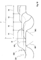
- Fig. 7 is a perspective view of a field-tested end mill. It can be seen in this figure that the chip breaker grooves 32 are introduced, preferably ground in, in such a way that they are slightly inclined to a plane of the end mill that is perpendicular to the milling cutter axis 21.
- This shaping can be implemented, for example, in that a profiled grinding wheel is used to grind in the chip breaker grooves, which has a profile according to the detail drawing Fig. 2 has, ie an outer contour with the radii R40, RF1 and RF2.
- This grinding wheel can be set at a predetermined angle to the plane of the end mill perpendicular to the milling cutter axis 21, so that the profile grinding wheel can move along a helix whose pitch corresponds to the pitch T of the roughing profile 30 with the chip breaker grooves 32.
- Fig. 8 is schematically indicated the end view of an example of the end mill not belonging to the invention.
- the arrangement is made such that the circumferential cutting edges 126-1 to 126-4 are equally divided on the milling cutter face.
- the plane of section VV in Fig. 3 in this variant lies on the cutter face.
- Fig. 9 a modified embodiment of the end mill is indicated, in which the chip breaker grooves labeled 232 are oriented slightly differently than in the embodiment described above. How out Fig. 9 As can be seen, the chip breaker grooves 232 run parallel to a normal plane to the cutter axis 221.
- the dimension of the chip thickness DS1 is slightly less than the dimension of the following chip thickness DS2 if the circumferential distance of the circumferential cutting edges that come into engagement one after the other is greater than the circumferential distance in front of it.
- the entire end mill consists of hard material, in particular solid hard metal, which results in improved rigidity and an even lower susceptibility to vibrations. With suitable coatings, it is possible to optimize the service life of the end mill.
- the geometry of the roughing profile in particular the ratio of the pitch to the axial length of the flattened section and / or the ratio of the pitch to the depth of the chip breaker groove, is selected as a function of the physical properties of the material to be machined.
- the roughing profile is equipped with a completely flattened central section 34.
- This geometry is not absolutely necessary in order to achieve the advantages according to the invention to a significant extent.
- the central section can also be rounded, preferably slightly bulged or convex, which is shown below with reference to the Figure 11 should be explained in more detail.
- the individual chip breaker grooves 332 have a rounded groove base 340 with a smallest groove radius RN.
- the chip splitting groove 332 merges over a first flank radius RF1 into a slightly convex but still essentially flattened central section 334.
- the flank radius RF1 is located on the side of the chip breaker groove 332 that faces away from the cutter shank.
- the respective chip splitting groove 332 merges into the central section 334 of the roughing profile via a second flank radius RF2.
- the division of the roughing profile i.e. the axial distance between adjacent chip breaker grooves 332 of a circumferential cutting edge is again designated by T, and the depth of the roughing profile 30 by H.
- the contour of the roughing profile can be formed by four circular line segments.
- the section with RF1 is followed by the section with RN, this is followed by the section with RF2 and this is followed by the section with the radius RK, which in the range of the size of the groove radius RN can, however, also be substantially, preferably many times larger than this .
- the central section 334 can also - deviating from a circular line - be formed by another curved curve.
- the convexity K of the profile in the area of the central section 334 is preferably small.
- K LB ⁇ 0.05 .
- the dimension LB denotes the profile length between the flank radii RF1 and RF2.
- the cutting part can be designed with other, conventional cutting edge geometries.
- cutting inserts can also be used.
- the cutting parts can be rectangular, with a corner bevel or with a spherical head.
- the roughing profile in the individual circumferential cutting edges can also be divided unevenly, that is, irregularly over the axial length. It is also possible to change the cross-section of the chip breaker grooves in the circumferential direction.
- a different profile can be formed on the various milling webs. It is also possible to expose individual circumferential cutting edges or diametrical pairs of cutting edges to the circumferential cutting edges.
- a modification can be made such that, with 4 circumferential cutting edges, the cutting edges 1 and 3 are equipped with a roughing profile, while the cutting edges 2 and 4 are smooth-edged.
Landscapes
- Engineering & Computer Science (AREA)
- Mechanical Engineering (AREA)
- Milling Processes (AREA)
- Drilling Tools (AREA)
Description
Die Erfindung betrifft einen Schaftfräser gemäß dem Oberbegriff des Patentanspruchs 1. Beispielsweise ist ein solcher Schaftfräser aus
Derartige Fräser haben als gemeinsames Merkmal einen Schaft als Einspannteil, der in die Werkzeugaufnahme eingesetzt ist. Solche Fräser sind beispielsweise als Langlochfräser oder Gesenkfräser mit flacher oder runder Stirn im Einsatz. Solche Fräser zeichnen sich ferner dadurch aus, dass sie im Bereich ihres Schneidabschnitts an den durch Spannuten voneinander getrennten Fräserstegen eine Mehrzahl von wendelförmig verlaufenden Umfangsschneidkanten haben, die jeweils mit einem Schruppprofil in der Weise ausgestaltet sind, dass die Umfangsschneidkanten Spanteilernuten erhalten, wobei die Spanteilernuten von in Umfangsrichtung benachbarten Fräserstegen axial zueinander versetzt sind.Such milling cutters have as a common feature a shank as a clamping part, which is inserted into the tool holder. Such milling cutters are used, for example, as slot milling cutters or die milling cutters with a flat or round face. Such milling cutters are also characterized in that they have a plurality of helically extending circumferential cutting edges in the area of their cutting section on the milling webs separated from one another by flutes, each of which is designed with a roughing profile in such a way that the circumferential cutting edges receive chip breaker grooves, the chip breaker grooves of in the circumferential direction adjacent milling webs are axially offset from one another.
Derartige Schruppprofile sind beispielsweise in der DIN 1836 in den Ausführungen "rund" und "flach" genormt, wobei bezüglich der Struktur des Profils, ggfs. bezüglich der Steigung, mit der die Spanteilernuten in die Fräserstege eingebracht werden, zwischen "extra-grob", "grob" und "fein" unterschieden wird. Die Profilstruktur, wie z.B. auch diese Steigungen der die Spanteilernuten ausbildenden Ausnehmungen, sind werkstoffabhängig, wobei mit zunehmender Härte des zu zerspanenden Werkstoffs die Steigung feiner gewählt wird. Die Steigung kann darüber hinaus vom Werkzeugdurchmesser abhängig sein, wobei in diesem Fall gilt, dass die Steigung umso feiner ist, je kleiner der Durchmesser des Schaftfräsers ist.Such roughing profiles are standardized, for example, in DIN 1836 in the versions "round" and "flat", whereby with regard to the structure of the profile, if necessary with regard to the slope with which the chip breaker grooves are made in the milling webs, between "extra-coarse", A distinction is made between "coarse" and "fine". The profile structure, such as the gradients of the recesses forming the chip breaker grooves, are material-dependent, with the gradient being selected to be finer as the hardness of the material to be machined increases. The pitch can also be dependent on the tool diameter, in which case the rule is that the smaller the diameter of the end mill, the finer the pitch.
Im Gegensatz zu Schlichtfräsern, die üblicherweise keine Profilierung der Schneide oder der Spanfläche besitzen, ermöglicht das unterbrochene, d.h. profilierte Profil der Werkzeugschneide der Schruppfräser ein schnelleres Brechen des Spans. Der Schruppfräser ist aber in der Regel nicht für die Herstellung einer gleichmäßigen Oberfläche mit hoher Oberflächengüte geeignet. Aufgrund des kurzspanenden Verhaltens des abgetragenen Materials ergibt sich jedoch eine wesentlich bessere Spanabfuhr als beim Schlichtfräser. Aufgrund des hohen Zeitspanungsvolumens eignen sich Schruppfräswerkzeuge der eingangs beschriebenen Art auch hervorragend für Arbeitsgänge, bei denen es gilt, bis auf ein Schlichtmaß von beispielsweise 0,5 mm möglichst effektiv und schnell Material vor einem Arbeitsgang mit einem Schlichtfräswerkzeug abzunehmen. Im Übrigen sind der Schnittdruck und die Leistungsaufnahme der Maschine beim Arbeiten mit solchen Schruppfräsern geringer, und das Werkzeug kann eine hohe Schnitttiefe und Schnittbreite fahren.In contrast to finishing cutters, which usually do not have a profiling of the cutting edge or the rake face, the interrupted, ie profiled, profile of the tool cutting edge enables the roughing cutter to break the chip more quickly. As a rule, however, the roughing cutter is not suitable for producing a uniform surface with a high surface quality. Due to the short-chipping behavior of the removed material, however, the result is a significantly better one Chip evacuation than with the finishing cutter. Due to the high metal removal rate, roughing milling tools of the type described at the beginning are also ideally suited for operations in which the aim is to remove material as effectively and quickly as possible with a finishing milling tool up to a finishing dimension of, for example, 0.5 mm. In addition, the cutting pressure and the power consumption of the machine are lower when working with such roughing cutters, and the tool can drive a high cutting depth and cutting width.
Auf der anderen Seite sind Schlichtfräser, also Schaftfräser mit glatten Schneiden, zwar in der Lage, eine Werkstückoberfläche mit hoher Maßhaltigkeit und Güte, d.h. Glattheit herzustellen, was sich aufgrund der Regelmäßigkeit der Werkzeugschneide, der hohen Drehzahl bei gleichzeitig niedriger Vorschubgeschwindigkeit des Fräswerkzeugs sowie des in der Regel geringen Spanvolumens aufgrund des geringen Schlichtaufmaßes ergibt, das je nach Anwendungsgebiet zwischen 0,1 und 1,0 mm liegen kann. Wenn derartige Schlichtfräser jedoch mit größeren Zustelltiefen bzw. Zustellbreiten eingesetzt werden, treten aufgrund der längeren und größeren Späne zum einen Spanabfuhrprobleme auf, und zum anderen erhöht sich die Leistungsaufnahme und der Schnittdruck überproportional. Um die dadurch einhergehende Neigung zu Schwingungen zu verringern, hat man - wie beispielsweise im Dokument
Durch diese unterschiedlichen Drallwinkel können Vibrationen des Fräswerkzeugs minimiert werden, was zu einer Erhöhung der Standzeit bzw. im Umkehrschluss zu einer Erhöhung der Vorschubwerte genutzt werden kann. Aufgrund der nach wie vor verhältnismäßig hohen Leistungsaufnahme und des hohen Schnittdrucks ebenso wie der kritischen Spanabfuhr kann auch dieser bekannte Schlichtfräser nur mit verhältnismäßig kleinen Schnittbreiten gefahren werden.These different helix angles can minimize vibrations of the milling tool, which can be used to increase the service life or, conversely, to increase the feed rates. Due to the still relatively high power consumption and the high cutting pressure as well as the critical chip evacuation, this known finishing cutter can only be operated with relatively small cutting widths.
Der Erfindung liegt deshalb die Aufgabe zugrunde, einen Schaftfräser der eingangs beschriebenen Art, insbesondere gemäß dem Oberbegriff des Patentanspruchs 1 in der Weise weiterzubilden, dass er sich bei Sicherstellung hoher Standwege, bei geringer Leistungsaufnahme der Maschine und bei reduziertem Schnittdruck in besonderer Weise dafür eignet, ein hohes Zeitspanungsvolumen bereitzustellen und gleichzeitig das Werkstück mit guter Oberflächenqualität zu bearbeiten.The invention is therefore based on the object of developing an end mill of the type described at the outset, in particular according to the preamble of claim 1, in such a way that, while ensuring higher Tool life, with low machine power consumption and reduced cutting pressure, particularly suitable for providing a high material removal rate and at the same time machining the workpiece with good surface quality.
Diese Aufgabe wird durch die Merkmale des Patentanspruchs 1 gelöst.This object is achieved by the features of claim 1.
Erfindungsgemäß wird die aus dem Bereich der Schlichtfräser bekannte Maßnahme der Variation des Drallwinkels der in Umfangsabstand zueinander stehenden Umfangsschneidkanten in vorteilhafter Weise mit einer neuen Geometrie der Spanteilernuten kombiniert, wodurch sich ein Fräswerkzeug ergibt, das hinsichtlich der Spanbildung, der Leistungsaufnahme der Maschine, des Schnittdrucks, der Spanabfuhr, der erzielbaren Schnittbreite und der Oberflächenqualität ausschließlich die Vorteile der herkömmlichen Schrupp- und Schlichtfräser kombiniert.According to the invention, the measure known from the field of finishing cutters of varying the helix angle of the circumferential cutting edges, which are circumferentially spaced from one another, is advantageously combined with a new geometry of the chip breaker grooves, resulting in a milling tool which, in terms of chip formation, the power consumption of the machine, the cutting pressure, the chip evacuation, the achievable cutting width and the surface quality only combine the advantages of conventional roughing and finishing cutters.
Der erfindungsgemäße Schaftfräser erzeugt nach wie vor kurze Späne und hat dadurch eine geringe Leistungsaufnahme. Ferner ist der Schnittdruck gering und aufgrund der kurzen Späne ergibt sich eine gute Spanabfuhr. Aufgrund des abgeflachten Schruppprofils in Verbindung mit der Maßnahme, dass zumindest zwei Umfangsschneidkanten unterschiedliche Drallwinkel aufweisen, wird die durch das Schruppprofil normalerweise vorgeprägte Schwingungsneigung des Fräsers erheblich reduziert, so dass über die vorzugsweise im Wesentlichen abgeflachten Bereiche des Schruppprofils bzw. mit einem Schruppschlichtprofil nach DIN 1836 qualitativ sehr hochwertige Oberflächen mit gutem Standweg herstellbar sind, da die Abrundungen der Spanteilernuten im Übergang zum vorzugsweise im Wesentlichen abgeflachten Abschnitt des Schruppprofils wirksam dafür sorgen, dass über die Standzeit des Werkzeugs ein weicher Schnitt bei minimierter Schlagbeanspruchung der Umfangsschneidkante sichergestellt ist. Das erfindungsgemäße Fräswerkzeug eignet sich auf diese Weise in besonderer Weise zum Arbeiten mit hohen Schnittbreiten und - tiefen, beispielsweise beim Nutenfräsen, wobei die Spanform ähnlich günstig wie beim reinen Schruppfräsen bleibt.The end mill according to the invention still produces short chips and therefore has a low power consumption. Furthermore, the cutting pressure is low and the short chips result in good chip evacuation. Due to the flattened roughing profile in connection with the measure that at least two circumferential cutting edges have different helix angles, the tendency of the milling cutter to vibrate, which is normally pre-marked by the roughing profile, is considerably reduced, so that over the preferably essentially flattened areas of the roughing profile or with a roughing-finishing profile according to DIN 1836 Very high quality surfaces with a good tool life can be produced, since the rounded edges of the chip breaker grooves in the transition to the preferably essentially flattened section of the roughing profile ensure that a soft cut is ensured over the life of the tool with minimized impact stress on the circumferential cutting edge. In this way, the milling tool according to the invention is particularly suitable for working with large cutting widths and depths, for example in slot milling, the chip shape remaining similarly favorable as in pure rough milling.
Der Wert der Dralllwinkelunterschiede im Bereich zwischen 1 und 6° wird in Abhängigkeit vom zu zerspanenden Werkstoff und/oder vom Werkstoff des Schaftfräsers und/oder von dessen Beschichtung gewählt.The value of the helix angle differences in the range between 1 and 6 ° is selected as a function of the material to be machined and / or the material of the end mill and / or its coating.
Vorteilhafte Weiterbildungen der Erfindung sind Gegenstand der Unteransprüche.Advantageous further developments of the invention are the subject of the subclaims.
Versuche haben gezeigt, dass es von Vorteil ist, den Flankenradius, über den die Spanteilernut in den abgeflachten Abschnitt des Schruppprofils übergeht, in dem Bereich zwischen 0,1 und 1,0 mm, besonders bevorzugst zwischen 0,1 und 0,5 mm zu legen, um die geforderten Standzeiten bei vorgegebener Oberflächenqualität einzuhalten.Tests have shown that it is advantageous to adjust the flank radius over which the chip splitting groove merges into the flattened section of the roughing profile in the range between 0.1 and 1.0 mm, particularly preferably between 0.1 and 0.5 mm in order to maintain the required service life with the given surface quality.
Für die Herstellung der Spanteilernuten kommen verschiedene Herstellungsmethoden in Betracht. Es ist beispielsweise möglich, die Spanteilernuten mittels einer Profilschleifscheibe in die Umfangsschneidkanten einzuschleifen. Gemäß einer Ausführungsform sind die Spanteilernuten zu einer auf einer Längsachse des Schaftfräsers senkrecht stehenden Ebene des Schaftfräsers angestellt, wodurch es gelingt, auf die Spanbildung in vorteilhafter Weise Einfluss zu nehmen. In diesem Fall können die Spanteilernuten jeweils abschnittsweise dem Verlauf einer Wendel folgen, deren Ganghöhe beispielsweise der Teilung des Schruppprofils oder einem ganzzahligen Vielfachen der Teilung entspricht.Various manufacturing methods can be used to manufacture the chip breaker grooves. For example, it is possible to grind the chip breaker grooves into the circumferential cutting edges using a profile grinding wheel. According to one embodiment, the chip breaker grooves are positioned in relation to a plane of the end mill that is perpendicular to a longitudinal axis of the end mill, whereby it is possible to influence the chip formation in an advantageous manner. In this case, the chip breaker grooves can each follow the course of a helix in sections, the pitch of which corresponds, for example, to the pitch of the roughing profile or to an integral multiple of the pitch.
Es ist jedoch auch gleichermaßen möglich, die Spanteilernuten parallel zu einer auf einer Längsachse des Schaftfräsers senkrecht stehenden Ebene des Schaftfräsers auszubilden.However, it is also equally possible to form the chip breaker grooves parallel to a plane of the end mill that is perpendicular to a longitudinal axis of the end mill.
Gemäß einer weiteren vorteilhaften Ausgestaltung ist der dem Fräserschaft jeweils zugewandte Flankenradius in der Spanteilernut kleiner als der andere Flankenradius, insbesondere für den Fall, dass der dem Fräserschaft zugewandte Flankenradius an der Spanbildung zuerst teilnimmt. Mit dieser Maßnahme kann die Standzeit des Schaftfräsers weiter erhöht werden, wobei gleichzeitig die Schwingungsneigung abnimmt und die Qualität der damit herstellbaren Oberfläche verbessert werden kann.According to a further advantageous embodiment, the flank radius facing the cutter shank in the chip splitting groove is smaller than the other flank radius, in particular in the event that the flank radius facing the cutter shank takes part in chip formation first. With this measure, the service life of the end mill can be increased further, while at the same time the tendency to vibrate decreases and the quality of the surface that can be produced with it can be improved.
Über die Wahl des Materials des Schaftfräsers lässt sich die Zerspanungsleistung, die Oberflächenqualität und die Standzeit des Werkzeugs weiter optimieren. Es hat sich herausgestellt, dass die erfindungsgemäße Gestaltung ihre besonderen Vorteile dann entfaltet, wenn das Werkzeug insgesamt oder zumindest im Bereich des Schneidabschnitts aus Hartstoff hergestellt ist, wobei als Hartstoff beispielsweise Vollhartmetall, aber auch ein Cermet-Werkstoff Verwendung finden kann.The machining performance, surface quality and tool life can be further optimized by choosing the material for the end mill. It has been found that the design according to the invention unfolds its particular advantages when the tool is made of hard material as a whole or at least in the area of the cutting section, with solid carbide, for example, but also a cermet material being able to be used as hard material.
Je nach Einsatzgebiet des Schaftfräsers, d.h. je nach Zerspanungsproblem, insbesondere je nach zu zerspanendem Werkstoff, kann es von Vorteil sein, den Schaftfräser mit einer innenliegenden Kühl-/Schmiermittelversorgung auszustatten und/oder mit einer geeigneten Beschichtung zu versehen. Als Beschichtungen kommen alle gängigen Hartstoffschichten, aber auch Weichstoff-Beschichtungen in Frage. Diesbezüglich wird beispielsweise auf die Beschichtungen verwiesen, die im
Nachstehend werden anhand schematischer Zeichnungen mehrere Ausführungsbeispiele der Erfindung näher beschrieben. Es zeigen:
-
Fig. 1 eine schematische Seitenansicht des Schaftfräsers mit vier Umfangsschneidkanten; -
Fig. 1A in vergrößerter Darstellung die Einzelheit "IA" inFig. 1 ; -
Fig. 2 in vergrößerter Darstellung einen Ausschnitt des erfindungsgemäßen Schruppprofils; -
Fig. 3 eine Seitenansicht des Schaftfräsers zur Verdeutlichung der Lage des Querschnitts, an dem die Umfangsschneidkanten in gleichem Winkelabstand zueinander angeordnet sind; -
Fig. 4 die Stirnansicht des Werkzeugs gemäßFig. 3 bei einer Blickrichtung entlang des Pfeils "IV"; -
Fig. 5 in vergrößerter Darstellung den Schnitt gemäß V-V inFig. 3 ; -
Fig. 6 eine schematische Abwicklung des Schaftfräsers gemäßFig. 3 ; -
Fig. 7 eine perspektivische Seitenansicht des erfindungsgemäßen Schaftfräsers; -
Fig. 8 die Stirnansicht eines modifizierten nicht zur Erfindung gehörenden Beispiels des Schaftfräsers, bei dem die Gleichteilung an der Stirnseite vorliegt; -
Fig. 9 eine Detailansicht einer Umfangsoberfläche eines modifizierten Ausführungsbeispiels des Schaftfräsers; -
Fig. 10 eine schematische Skizze zur Darstellung der Spanbildung benachbarter Umfangsschneidkanten; und -
Fig. 11 in vergrößerter Darstellung ein modifiziertes Schruppprofil.
-
Fig. 1 a schematic side view of the end mill with four peripheral cutting edges; -
Figure 1A the detail "IA" inFig. 1 ; -
Fig. 2 an enlarged view of a section of the roughing profile according to the invention; -
Fig. 3 a side view of the end mill to illustrate the position of the cross section on which the circumferential cutting edges are arranged at the same angular distance from one another; -
Fig. 4 the front view of the tool according toFig. 3 when looking along the arrow "IV"; -
Fig. 5 in an enlarged representation the section according to VV inFig. 3 ; -
Fig. 6 a schematic development of the end mill according toFig. 3 ; -
Fig. 7 a perspective side view of the end mill according to the invention; -
Fig. 8 the end view of a modified example, not belonging to the invention, of the end mill in which the uniform pitch is present on the end face; -
Fig. 9 a detailed view of a peripheral surface of a modified embodiment of the end mill; -
Fig. 10 a schematic sketch to illustrate the chip formation of adjacent peripheral cutting edges; and -
Fig. 11 a modified roughing profile in an enlarged view.
In
Mit der Linie 26 ist angedeutet, dass der Schaftfräser einen so genannten Halseinschliff hat, d.h. der Außendurchmesser des Spannschafts 24 ist geringfügig größer als der Nenndurchmesser des Schneidabschnitts 22.The
Der Schneidabschnitt 22 hat eine Mehrzahl von wendelförmig verlaufenden Umfangsschneidkanten 26-1 bis 26-n, zwischen denen Spannuten 28-1 bis 28-n ausgebildet sind. Bei diesem Schaftfräser stellen die Umfangsschneidkanten die Hauptschneiden dar. Stirnseitig ist eine der Anzahl der Umfangsschneidkanten entsprechende Anzahl von Nebenschneiden ausgebildet, und zwar in herkömmlicher Art und Weise, so dass eine nähere Beschreibung dieser Geometrie hier entfallen kann.The cutting
Wie sich aus der bzw. im Einzelnen aus der
In
Die Größen RF1, RF2, T und H, und damit auch das axiale Maß A34 des abgeflachten Abschnitts 34, sind variierbar, um eine Anpassung an die Zerspanungsbedingungen, d.h. an den zu zerspanenden Werkstoff, an die Schnittgeschwindigkeit und an das Zeitspanungsvolumen vorzunehmen. Es hat sich jedoch herausgestellt, dass folgende Bedingungen von besonderem Vorteil sind:
- 1. Der Flankenradius RF1 und RF2 sollte im Bereich zwischen 0,1 und 1 mm, besonders bevorzugt zwischen 0,1 und 0,5 mm liegen.
- 2. Die Größe des kleinsten Radius
RF40 im Grund 40der Spanteilernut 32 sollte größer sein als der Flankenradius RF1 bzw. RF2. - 3. Der beim Schneiden in Drehrichtung, d.h. in Schnittrichtung vorlaufende Flankenradius RF2 des in der Ausführungsform gemäß
Fig. 1 rechtsgedrallten Schaftfräsers, d.h. der dem Fräserschaft jeweils zugewandte Flankenradius RF2 der Spanteilernut, sollte größer sein als der dem Fräserschaft abgewandte Flankenradius RF1. Mit anderen Worten, derjenige Flankenradius, der beim Eintauchen des Schruppprofils in das Werkstück zuerst Schneidarbeit verrichtet, sollte größer an der andere Flankenradius sein.
- 1. The flank radius RF1 and RF2 should be in the range between 0.1 and 1 mm, particularly preferably between 0.1 and 0.5 mm.
- 2. The size of the smallest radius RF40 in the
base 40 of thechip breaker groove 32 should be larger than the flank radius RF1 or RF2. - 3. The flank radius RF2 of the leading edge in the direction of rotation when cutting in the direction of cutting in the embodiment according to FIG
Fig. 1 right-hand helical end mill, ie the flank radius RF2 of the chip splitter groove facing the cutter shank, should be greater than the flank radius RF1 facing away from the cutter shank. In other words, the flank radius that first performs cutting work when the roughing profile plunges into the workpiece should be larger on the other flank radius.
Bei der Ausführungsform des Schaftfräsers, die in den Zeichnungen gezeigt ist, ist eine gerade Anzahl von Umfangsschneidkanten 26-1 bis 26-4 vorgesehen, wobei jeweils zwei einander diametral gegenüberliegende Umfangsschneidkanten 26-1 und 26-3 bzw. 26-2 und 26-4 jeweils denselben Drallwinkel θ haben. Dies ist aus der
Anhand der Abwicklung gemäß
Wenn ferner die Drallwinkel einander diametral gegenüberliegender Umfangsschneidkanten 26-1 und 26-3 bzw. 26-2 und 26-4 gleich aber unterschiedlich groß sind, nämlich den Drallwinkel θ1 bzw. θ2 haben, ergibt sich auf der Stirnseite des Schaftfräsers - wie in
Die Ebene des Schnitts V-V in
Es hat sich als vorteilhaft herausgestellt, wenn das Maß AGT etwa 30% der Länge L22 des Schneidabschnitts 22 ausmacht.It has been found to be advantageous if the dimension AGT makes up approximately 30% of the length L22 of the
In
In den weiteren Figuren sind modifizierte Ausführungsformen gezeigt. Dabei sind diejenigen Komponenten, die den Bestandteilen des zuvor beschriebenen Fräsers entsprechen, mit ähnlichen Bezugszeichen versehen, denen aber eine "1", "2" bzw. "3" vorangestellt sind.Modified embodiments are shown in the other figures. Those components which correspond to the constituent parts of the milling cutter described above are provided with similar reference numerals, but which are preceded by a "1", "2" or "3".
In
In ![]()
![]()
Mit dem vorstehend beschriebenen Aufbau ergibt sich ein Schaftfräser, der sich insbesondere zur Bearbeitung von schwer zerspanbaren Werkstoffen unter Bereitstellung großer Schnittbreiten eignet, d.h. ein Schaftfräser insbesondere zum Flankenfräsen, Nutenfräsen, diagonalem Bohrfräsen oder spiraligem Formfräsen. Anhand der
Es ergibt sich aus dieser Darstellung, dass durch diese mehrfachen Unregelmäßigkeiten bei der Spanbildung, die sich über die axiale Länge des Schaftfräsers noch einmal ändern, der Gefahr von eigenschwingungsbedingten Werkzeug-Instabilitäten entgegengewirkt wird. Der erfindungsgemäße Schaftfräser arbeitet deshalb nicht nur mit optimalem Zeitspanungsvolumen, sondern darüber hinaus derart, dass selbst bei großen Schnittbreiten und guter Standzeit eine sehr gute Werkstückoberfläche realisiert werden kann.It can be seen from this illustration that these multiple irregularities in the formation of chips, which change again over the axial length of the end mill, counteract the risk of tool instabilities caused by natural vibrations. The end mill according to the invention therefore not only works with an optimal metal removal rate, but also in such a way that a very good workpiece surface can be achieved even with large cutting widths and a long service life.
Dieser vorteilhafte Effekt kann durch geeignete Materialwahl bei dem Aufbau des Schaftfräsers noch verstärkt werden. Gemäß einer vorteilhaften Weiterbildung besteht der gesamte Schaftfräser aus Hartstoff, insbesondere aus Vollhartmetall, wodurch sich eine verbesserte Steifigkeit und eine noch geringere Anfälligkeit bezüglich Schwingungen ergeben. Durch geeignete Beschichtungen gelingt es, die Standzeit des Schaftfräsers zusätzlich zu optimieren.This advantageous effect can be reinforced by a suitable choice of material in the construction of the end mill. According to an advantageous development, the entire end mill consists of hard material, in particular solid hard metal, which results in improved rigidity and an even lower susceptibility to vibrations. With suitable coatings, it is possible to optimize the service life of the end mill.
Vorzugsweise wird die Geometrie des Schruppprofils, insbesondere das Verhältnis von Teilung zur axialen Länge des abgeflachten Abschnitts und/oder das Verhältnis von Teilung zur Tiefe der Spanteilernut in Abhängigkeit von den physikalischen Eigenschaften des zu zerspanenden Werkstoffs ausgewählt.The geometry of the roughing profile, in particular the ratio of the pitch to the axial length of the flattened section and / or the ratio of the pitch to the depth of the chip breaker groove, is selected as a function of the physical properties of the material to be machined.
Bei allen zuvor beschriebenen Ausführungsformen ist das Schruppprofil mit einem vollkommen abgeflachten Zentralabschnitt 34 ausgestattet. Diese Geometrie ist jedoch nicht unbedingt erforderlich, um die erfindungsgemäßen Vorteile in maßgeblichen Umfang zu erzielen. Der Zentralabschnitt kann auch gerundet sein, vorzugsweise leicht ausgebaucht bzw. konvex, was nachfolgend anhand der
Auch bei diesem Schruppprofil 330 haben die einzelnen Spanteilernuten 332 einen gerundeten Nutgrund 340 mit einem kleinsten Nutenradius RN. Über einen ersten Flankenradius RF1 geht die Spanteilernut 332 in einen leicht konvexen, aber immer noch im Wesentlichen abgeflachten Zentralabschnitt 334 über. Der Flankenradius RF1 befindet sich auf der Seite der Spanteilernut 332, die dem Fräserschaft abgewandt ist. Auf der dem Fräserschaft zugewandten Seite geht die jeweilige Spanteilernut 332 über einen zweiten Flankenradius RF2 in den Zentralabschnitt 334 des Schruppprofils über. Die Teilung des Schruppprofils, d.h. der axiale Abstand benachbarter Spanteilernuten 332 einer Umfangsschneidkante ist wieder mit T bezeichnet, und die Tiefe des Schruppprofils 30 mit H.In this
Die Größen RF1, RF2, T und H, und damit auch das axiale Maß LB des im Wesentlichen abgeflachten, aber konvexen Abschnitts 334, sind wieder variierbar, um eine Anpassung an die Zerspanungsbedingungen, d.h. an den zu zerspanenden Werkstoff, an die Schnittgeschwindigkeit und an das Zeitspanungsvolumen vorzunehmen. Auch bei dieser Ausführungsform soll gelten:
- 1. Der Flankenradius RF1 und RF2 sollte im Bereich zwischen 0,1 und 1 mm liegen;
- 2. Die Größe des kleinsten Radius
RN im Grund 340der Spanteilernut 332 sollte größer sein als der Flankenradius RF1 bzw. RF2. - 3. Der beim Schneiden in Drehrichtung, d.h. in Schnittrichtung vorlaufende Flankenradius RF2 des in der Ausführungsform gemäß
Fig. 1 rechtsgedrallten Schaftfräsers, d.h. der dem Fräserschaft jeweils zugewandte Flankenradius RF2 der Spanteilernut, sollte größer sein als der dem Fräserschaft abgewandte Flankenradius RF1. Mit anderen Worten, derjenige Flankenradius, der beim Eintauchen des Schruppprofils in das Werkstück zuerst Schneidarbeit verrichtet, sollte größer als der andere Flankenradius sein.
- 1. The flank radius RF1 and RF2 should be in the range between 0.1 and 1 mm;
- 2. The size of the smallest radius RN in the
base 340 of thechip breaker groove 332 should be larger than the flank radius RF1 or RF2. - 3. The flank radius RF2 of the leading edge in the direction of rotation when cutting in the direction of cutting in the embodiment according to FIG
Fig. 1 right-hand helical end mill, ie the flank radius RF2 of the chip splitter groove facing the cutter shank, should be greater than the flank radius RF1 facing away from the cutter shank. In other words, the flank radius that first performs cutting work when the roughing profile plunges into the workpiece should be larger than the other flank radius.
Bei dem Ausführungsbeispiel der
Vorzugsweise ist die Balligkeit K des Profils im Bereich des Zentralabschnitts 334 gering. Vorzugsweise gilt unter Bezug auf die ![]()
![]()
Selbstverständlich sind Abweichungen von dem beschriebenen Ausführungsbeispiel möglich, ohne den Grundgedanken der Erfindung zu verlassen.Of course, deviations from the exemplary embodiment described are possible without departing from the basic concept of the invention.
So kann beispielsweise das Schneidteil mit anderen, herkömmlichen Schneidengeometrien ausgeführt werden.For example, the cutting part can be designed with other, conventional cutting edge geometries.
Es ist auch möglich, das Werkzeug mit einer innenliegenden Kühl-/Schmiermittelversorgung auszustatten.It is also possible to equip the tool with an internal coolant / lubricant supply.
Anstelle von einstückig mit dem Schaftfräserwerkstoff ausgebildeten Schneidkanten können auch Schneideinsätze verwendet werden.Instead of cutting edges formed in one piece with the end mill material, cutting inserts can also be used.
Es ist darüber hinaus möglich, die Stirngeometrie des Fräsers in weiten Grenzen zu ändern. Die Schneidteile können rechteckig, mit Eckenfase oder mit Kugelkopf ausgebildet werden.It is also possible to change the face geometry of the milling cutter within wide limits. The cutting parts can be rectangular, with a corner bevel or with a spherical head.
Auch das Schruppprofil in den einzelnen Umfangsschneidkanten kann ungleich geteilt sein, also unregelmäßig über die axiale Länge. Es ist auch möglich, den Querschnitt der Spanteilernuten in Umfangsrichtung zu verändern.The roughing profile in the individual circumferential cutting edges can also be divided unevenly, that is, irregularly over the axial length. It is also possible to change the cross-section of the chip breaker grooves in the circumferential direction.
Schließlich kann auf den verschiedenen Fräserstegen ein unterschiedliches Profil ausgebildet sein. Es ist auch möglich, einzelne Umfangsschneidkanten bzw. diametrale Schneidenpaare der Umfangsschneiden auszusetzen. Mit anderen Worten: Es kann z.B. eine Abwandlung derart getroffen sein, dass bei 4 Umfangsschneidkanten die Schneiden 1 und 3 mit einem Schruppprofil ausgestattet sind, während die Schneiden 2 und 4 glattschneidig sind.Finally, a different profile can be formed on the various milling webs. It is also possible to expose individual circumferential cutting edges or diametrical pairs of cutting edges to the circumferential cutting edges. In other words: For example, a modification can be made such that, with 4 circumferential cutting edges, the cutting edges 1 and 3 are equipped with a roughing profile, while the
Claims (16)
- An end mill cutter which has in the region of its cutting portion (22) a plurality of peripheral cutting edges (26-1 to 26-n) running in a helical shape, of which at least a decisive number are each equipped with a substantially flattened roughing profile (30, 330) with chip-separating grooves (32; 332) which are rounded in the base (40, 340), in such a manner that the chip-separating grooves of cutter ridges (36-1, 36-2, 36-3, 36-4) that are adjacent in the peripheral direction are axially offset from one another, the chip-separating grooves (32, 332) each merging via a predefined flank radius (RF1, RF2) into a substantially flattened central portion (34; 334) of the roughing profile (30), characterisedin thatat least one peripheral cutting edge (26-1) has an angle of twist (Θ 1) which differs from the angle of twist (Θ 2) of another peripheral cutting edge (26-2), whereinthe angles of twist (Θ 1 , Θ 2) of adjacent peripheral cutting edges (26-1 , 26-2) are different and an even number of peripheral cutting edges (26-1 to 26-4) is provided, of which in each case two lie diametrically opposite each other and have the same angle of twist (Θ 1 and Θ 3, and Θ 2 and Θ 4), andthe angles of twist (Θ) of the peripheral cutting edges (26) differ by from 1° to 6° , preferably by from 1° to 3° , whereinthe pitch of the cutter is equal in a radial plane (V-V) lying in the region of the cutting portion (22) at a predetermined distance AGT from the cutter front and perpendicular to the cutter axis 21.
- An end mill cutter according to claim 1, characterised in that the flank radius (RF1, RF2) lies in the range from 0.1 to 1.0 mm.
- An end mill cutter according to claim 1 or 2, characterised in that the flank radius (RF1) that is remote from the cutter shank in each case is smaller than the other flank radius (RF2) of the chip-separating groove (32).
- An end mill cutter according to any one of claims 1 to 3, characterised in that the chip-separating grooves (32) are angled towards a plane of the end mill cutter '(20), which plane is perpendicular to a longitudinal axis (21) of the end mill cutter.
- An end mill cutter according to claim 4, characterised in that the chip-separating grooves (32) in each case follow in portions the course of a helix the lead of which corresponds to the pitch (T) of the roughing profile (30) formed with the chip-separating groove (32).
- An end mill cutter according to any one of claims 1 to 3, characterised in that the chip-separating grooves (232) are parallel to a plane of the end mill cutter (220), which plane is perpendicular to a longitudinal axis (221) of the end mill cutter.
- An end mill cutter according to claim 6, characterised in that the chip-separating grooves (232) of cutter ridges (236-1 , 236-2) that are adjacent in the peripheral direction are axially offset from one another by the quantity V, where:

- An end mill cutter according to any one of claims 1 to 7, characterised in that the flank radius (RF1, Rf2) is smaller than the smallest radius (R40; RN) in the base (40; 340) of the rounded chip-separating grooves (32; 332).
- An end mill cutter according to any one of claims 1 to 8, characterised in that the angles of twist (Θ) are between 20 and 55°.
- An end mill cutter according to any one of claims 1 to 9, characterised in that it consists of a hard material, especially solid carbide (SC), at least in the region of the cutting portion (22).
- An end mill cutter according to any one of claims 1 to 10, characterised in that it is provided with a coating, especially a PVD coating, at least in the region of the cutting portion (22).
- An end mill cutter according to any one of claims 1 to 11, characterised in that the geometry of the roughing profile (30), especially the ratio of pitch (T) to axial length (A34) of the preferably substantially flattened central portion (34; LB) and/or the ratio of pitch (T) to depth (H) of the chip-separating groove (32; 332) is selected in dependence on the physical properties of the material to be machined.
- An end mill cutter according to any one of claims 1 to 12, characterised in that the roughing profile is substantially identical in all the sectional planes containing a longitudinal axis (21; 221) of the end mill cutter.
- An end mill cutter according to any one of claims 1 to 13, characterised in that the central portion (334) lying between the chip-separating grooves (332) has a convexly curved surface.
- An end mill cutter according to claim 14, characterised in that the radius of curvature (RK) of the central portion (334) is considerably greater than the flank radius (RF1, RF2).
- Use of an end mill cutter according to any one of claims 1 to 15 for machining with large cutting widths, especially for side milling, slot milling, diagonal drilling and milling, or spiral form milling.
Applications Claiming Priority (3)
| Application Number | Priority Date | Filing Date | Title |
|---|---|---|---|
| DE102009012012 | 2009-03-07 | ||
| DE102009002738A DE102009002738A1 (en) | 2009-03-07 | 2009-04-29 | End mills |
| PCT/DE2010/000249 WO2010102605A1 (en) | 2009-03-07 | 2010-03-08 | End mill cutter |
Publications (3)
| Publication Number | Publication Date |
|---|---|
| EP2403673A1 EP2403673A1 (en) | 2012-01-11 |
| EP2403673B1 EP2403673B1 (en) | 2013-06-19 |
| EP2403673B2 true EP2403673B2 (en) | 2021-12-08 |
Family
ID=42628609
Family Applications (1)
| Application Number | Title | Priority Date | Filing Date |
|---|---|---|---|
| EP10713554.3A Active EP2403673B2 (en) | 2009-03-07 | 2010-03-08 | End mill cutter |
Country Status (4)
| Country | Link |
|---|---|
| US (3) | US20100226726A1 (en) |
| EP (1) | EP2403673B2 (en) |
| DE (1) | DE102009002738A1 (en) |
| WO (1) | WO2010102605A1 (en) |
Families Citing this family (38)
| Publication number | Priority date | Publication date | Assignee | Title |
|---|---|---|---|---|
| US8414228B2 (en) * | 2006-01-04 | 2013-04-09 | Sgs Tool Company | Rotary cutting tool |
| WO2010137429A1 (en) * | 2009-05-25 | 2010-12-02 | 日立ツール株式会社 | Carbide end mill and cutting method using the end mill |
| US20110033251A1 (en) * | 2009-08-04 | 2011-02-10 | Kennametal Inc. | Rotary cutting tool with reverse chipbreaker pattern |
| IL203283A (en) * | 2010-01-13 | 2014-02-27 | Iscar Ltd | Cutting insert |
| USD632319S1 (en) * | 2010-02-25 | 2011-02-08 | Gn Tool Co., Ltd. | Endmill |
| JP5649729B2 (en) * | 2011-07-05 | 2015-01-07 | オーエスジー株式会社 | Unequal lead end mill |
| USD701255S1 (en) * | 2012-08-08 | 2014-03-18 | Dasan Machineries Co., Ltd. | Double end mill |
| US10265784B2 (en) * | 2012-10-29 | 2019-04-23 | Kyocera Corporation | Ball end mill |
| DE102013206249A1 (en) * | 2013-04-09 | 2014-10-23 | MAPAL Fabrik für Präzisionswerkzeuge Dr. Kress KG | milling tool |
| JP6089917B2 (en) * | 2013-04-19 | 2017-03-08 | 株式会社不二越 | Unequal lead end mill |
| DE102013015261A1 (en) * | 2013-09-16 | 2015-03-19 | Franz Haimer Maschinenbau Kg | Cutter with cord made of a special tooth profile |
| CN104439466A (en) * | 2013-09-24 | 2015-03-25 | 上海冠钻精密工具有限公司 | Milling cutter |
| JP6221660B2 (en) * | 2013-11-12 | 2017-11-01 | 三菱マテリアル株式会社 | Roughing end mill |
| DE102014103103A1 (en) * | 2014-03-07 | 2015-09-10 | Gühring KG | End mills |
| US20150258616A1 (en) * | 2014-03-11 | 2015-09-17 | Frank J Stanbach | End mill |
| CN104191019A (en) * | 2014-08-01 | 2014-12-10 | 常州创伟工具制造有限公司 | Double-helix two-edge end mill |
| US10118236B2 (en) * | 2014-09-26 | 2018-11-06 | Kennametal Inc. | Rotary cutting tool |
| JP5958614B2 (en) * | 2015-07-06 | 2016-08-02 | 三菱マテリアル株式会社 | Ball end mill |
| US10052700B2 (en) | 2015-07-28 | 2018-08-21 | Kennametal Inc. | Rotary cutting tool with blades having repeating, unequal indexing and helix angles |
| BE1023432B1 (en) * | 2016-01-21 | 2017-03-17 | Safran Aero Boosters S.A. | Strawberry |
| JP6879668B2 (en) * | 2016-03-15 | 2021-06-02 | 国立大学法人 名古屋工業大学 | Cutting method |
| CN105618828A (en) * | 2016-04-08 | 2016-06-01 | 苏州阿诺精密切削技术股份有限公司 | Fracture-toothed rough milling cutter |
| DE102016006995B3 (en) * | 2016-06-09 | 2017-10-19 | Hufschmied Zerspanungssysteme Gmbh | Electrode graphite cutter |
| CN106238793A (en) * | 2016-09-19 | 2016-12-21 | 山东大学 | A kind of false boss slotting cutter |
| CN106624097A (en) * | 2016-12-09 | 2017-05-10 | 海南中智康弘精工技术有限公司 | Vortex corrugated edge milling cutter |
| WO2018110697A1 (en) * | 2016-12-15 | 2018-06-21 | 京セラ株式会社 | Rotating tool |
| CN106735492B (en) * | 2017-02-15 | 2018-10-26 | 海南中智康弘精工技术有限公司 | A kind of milling cutter |
| US11926005B2 (en) * | 2017-08-03 | 2024-03-12 | Vestas Wind Systems A/S | Mill bit for the manufacture of a wind turbine blade and method of forming same |
| DE102017118943A1 (en) * | 2017-08-18 | 2019-02-21 | Datron Ag | milling tool |
| CN107766647B (en) * | 2017-10-19 | 2020-12-29 | 湖北工业大学 | A Numerical Calculation Method of Forming Milling Cutter Profile for Machining Elliptical Helical Rotors |
| CN115702053B (en) * | 2020-06-22 | 2025-07-04 | 住友电工硬质合金株式会社 | Cutting Tools |
| KR102213944B1 (en) * | 2020-08-19 | 2021-02-08 | 한상오 | Sponge processing tool and sponge processing method using the same |
| CN113118531B (en) * | 2021-04-16 | 2022-06-14 | 江苏科技大学 | Universal end mill for roughing and finishing with chipbreaker |
| JP7564493B2 (en) * | 2021-05-31 | 2024-10-09 | 株式会社Moldino | End Mills |
| EP4201564A1 (en) * | 2021-12-23 | 2023-06-28 | Walter AG | End mill |
| EP4454794A4 (en) * | 2021-12-24 | 2025-11-19 | Osg Corp | STRAWBERRY END |
| US12350745B2 (en) * | 2023-02-01 | 2025-07-08 | Sumitomo Electric Hardmetal Corp. | Cutting tool |
| CZ2024165A3 (en) * | 2024-04-25 | 2025-08-06 | UniCut s.r.o. | A shank milling cutter |
Citations (6)
| Publication number | Priority date | Publication date | Assignee | Title |
|---|---|---|---|---|
| US4285618A (en) † | 1979-10-12 | 1981-08-25 | Shanley Stephen E Jr | Rotary milling cutter |
| DE3706282A1 (en) † | 1986-02-28 | 1987-09-03 | Izumo Sangyo Kk | CIRCULAR CUTTING TOOL |
| DE29715192U1 (en) † | 1997-08-23 | 1997-12-04 | Schuler Technoplan GmbH & Co. KG, 75417 Mühlacker | Milling tool |
| US7001113B2 (en) † | 2001-09-10 | 2006-02-21 | Flynn Clifford M | Variable helix cutting tools |
| EP1894655A1 (en) † | 2006-08-28 | 2008-03-05 | Fraisa Holding AG | Milling tool for chip removing machining of workpieces |
| US7367754B1 (en) † | 2006-07-07 | 2008-05-06 | Greenwood Mark L | Variable helix rotary cutting tool |
Family Cites Families (13)
| Publication number | Priority date | Publication date | Assignee | Title |
|---|---|---|---|---|
| US3736634A (en) * | 1971-03-17 | 1973-06-05 | Hicarb Corp | Rotary cutting tool |
| DE7705745U1 (en) * | 1977-02-25 | 1977-06-02 | Hawera Probst Gmbh + Co, 7980 Ravensburg | CUTTERS, IN PARTICULAR CONTOUR CUTTERS |
| DE8110928U1 (en) * | 1981-04-10 | 1981-12-03 | BIAX-Werkzeuge KG, Wezel & Co, Präzisionswerkzeugfabrik, 7133 Maulbronn | MILLING TOOL |
| US4770567A (en) * | 1983-06-20 | 1988-09-13 | Colt Industries Operating Corp. | Roughing cutter |
| US4810136A (en) * | 1983-11-09 | 1989-03-07 | The Boeing Company | Milling cutter for composite laminates |
| FR2875722A1 (en) * | 2004-09-27 | 2006-03-31 | Alsameca Sa | Cutter for e.g. piercing ferrous material, has sets of teeth with cutting edges separated in pairs by different angles and with different geometric or dimensional characteristic, on preset cutting section |
| JP4553251B2 (en) * | 2005-04-13 | 2010-09-29 | オーエスジー株式会社 | Threading cutter |
| US7399147B1 (en) * | 2005-08-09 | 2008-07-15 | Vandyke Jr Daryl C | End mill bit with notched teeth |
| IL177336A (en) * | 2006-08-07 | 2013-05-30 | Hanita Metal Works Ltd | Chatter-resistant end mill |
| DE202006016531U1 (en) | 2006-10-28 | 2007-07-19 | Hofmann & Vratny Ohg | Workpiece upper surface smoothing/roughing miller, has milling surfaces with rough and smooth regions, where each smooth plain region lies in axial direction of miller on identical axial height of rough region of adjacent milling surface |
| DE102007021562B4 (en) | 2007-05-08 | 2012-05-03 | Kmp Printtechnik Ag | ink cartridge |
| WO2009122937A1 (en) * | 2008-03-31 | 2009-10-08 | 住友電工ハ-ドメタル株式会社 | End mill |
| DE102008018399A1 (en) * | 2008-04-10 | 2009-10-15 | Sandvik Intellectual Property Ab | End mill with different helix angles |
-
2009
- 2009-04-29 DE DE102009002738A patent/DE102009002738A1/en not_active Withdrawn
- 2009-07-31 US US12/533,269 patent/US20100226726A1/en not_active Abandoned
-
2010
- 2010-03-08 EP EP10713554.3A patent/EP2403673B2/en active Active
- 2010-03-08 WO PCT/DE2010/000249 patent/WO2010102605A1/en not_active Ceased
-
2012
- 2012-09-27 US US13/628,370 patent/US20130022416A1/en not_active Abandoned
-
2015
- 2015-01-27 US US14/606,186 patent/US9352400B2/en not_active Expired - Fee Related
Patent Citations (6)
| Publication number | Priority date | Publication date | Assignee | Title |
|---|---|---|---|---|
| US4285618A (en) † | 1979-10-12 | 1981-08-25 | Shanley Stephen E Jr | Rotary milling cutter |
| DE3706282A1 (en) † | 1986-02-28 | 1987-09-03 | Izumo Sangyo Kk | CIRCULAR CUTTING TOOL |
| DE29715192U1 (en) † | 1997-08-23 | 1997-12-04 | Schuler Technoplan GmbH & Co. KG, 75417 Mühlacker | Milling tool |
| US7001113B2 (en) † | 2001-09-10 | 2006-02-21 | Flynn Clifford M | Variable helix cutting tools |
| US7367754B1 (en) † | 2006-07-07 | 2008-05-06 | Greenwood Mark L | Variable helix rotary cutting tool |
| EP1894655A1 (en) † | 2006-08-28 | 2008-03-05 | Fraisa Holding AG | Milling tool for chip removing machining of workpieces |
Non-Patent Citations (3)
| Title |
|---|
| Informationsblatt der Fa. Hommel Hercules zu Fräsertypen, DIN 1836, Januar 1984 † |
| Produktkatalog 03/2007, Fa. Rübig † |
| Produktkatalog 2009, Fa. Dormer † |
Also Published As
| Publication number | Publication date |
|---|---|
| US20130022416A1 (en) | 2013-01-24 |
| US20100226726A1 (en) | 2010-09-09 |
| EP2403673B1 (en) | 2013-06-19 |
| DE102009002738A1 (en) | 2010-09-23 |
| US9352400B2 (en) | 2016-05-31 |
| EP2403673A1 (en) | 2012-01-11 |
| WO2010102605A1 (en) | 2010-09-16 |
| US20150158095A1 (en) | 2015-06-11 |
Similar Documents
| Publication | Publication Date | Title |
|---|---|---|
| EP2403673B2 (en) | End mill cutter | |
| EP1864737B1 (en) | Tool for chip-removal | |
| EP2323792B1 (en) | Multiple edge drill | |
| EP3150313B1 (en) | Solid milling tool for machining rotating materials | |
| DE102015112417B4 (en) | Rotary cutting tool with regrindable cutting inserts | |
| EP1511590B1 (en) | Milling cutter having a wiper radius | |
| EP0937528A1 (en) | Reaming tool and its manufactoring method | |
| DE112011102667T5 (en) | Contour end mill | |
| DE3831535A1 (en) | HEAD MILLING | |
| DE102016206721A1 (en) | Cutting tool for improved chip removal and method for its production | |
| EP3356071B1 (en) | Finishing tool, in particular end milling cutter | |
| WO2016020047A1 (en) | Milling tool | |
| DE102005002698B4 (en) | milling tool | |
| DE112017000520B4 (en) | End mill and method of making a machined product | |
| EP1907158B1 (en) | Cutting insert, tool and method of machining a workpiece | |
| WO2008052503A1 (en) | Finishing/roughing mill | |
| EP2929966B1 (en) | Solid milling tool for machining of materials | |
| DE102005038021B4 (en) | Method for machining crankshafts and apparatus for carrying out this method | |
| DE102004022360B4 (en) | Process for fine machining, preferably for precision finishing, of workpieces, preferably crankshafts | |
| EP0485546B1 (en) | Cutting insert for tools | |
| EP3630400A1 (en) | Single-lip deep-hole drill with a chamfered rake face | |
| EP2420337B1 (en) | Use of an indexable tip for bevelling, and combination of a conical or cylindrical milling head with an indexable tip for bevelling | |
| DE102005058536B4 (en) | Cutting tool system, in particular for splining bevel gears in the single-part method | |
| DE112022007377T5 (en) | Thread milling cutter | |
| DE202023100349U1 (en) | Full milling tool for rotating material processing |
Legal Events
| Date | Code | Title | Description |
|---|---|---|---|
| PUAI | Public reference made under article 153(3) epc to a published international application that has entered the european phase |
Free format text: ORIGINAL CODE: 0009012 |
|
| 17P | Request for examination filed |
Effective date: 20110929 |
|
| AK | Designated contracting states |
Kind code of ref document: A1 Designated state(s): AT BE BG CH CY CZ DE DK EE ES FI FR GB GR HR HU IE IS IT LI LT LU LV MC MK MT NL NO PL PT RO SE SI SK SM TR |
|
| DAX | Request for extension of the european patent (deleted) | ||
| GRAP | Despatch of communication of intention to grant a patent |
Free format text: ORIGINAL CODE: EPIDOSNIGR1 |
|
| GRAJ | Information related to disapproval of communication of intention to grant by the applicant or resumption of examination proceedings by the epo deleted |
Free format text: ORIGINAL CODE: EPIDOSDIGR1 |
|
| GRAP | Despatch of communication of intention to grant a patent |
Free format text: ORIGINAL CODE: EPIDOSNIGR1 |
|
| GRAC | Information related to communication of intention to grant a patent modified |
Free format text: ORIGINAL CODE: EPIDOSCIGR1 |
|
| GRAP | Despatch of communication of intention to grant a patent |
Free format text: ORIGINAL CODE: EPIDOSNIGR1 |
|
| GRAS | Grant fee paid |
Free format text: ORIGINAL CODE: EPIDOSNIGR3 |
|
| GRAA | (expected) grant |
Free format text: ORIGINAL CODE: 0009210 |
|
| AK | Designated contracting states |
Kind code of ref document: B1 Designated state(s): AT BE BG CH CY CZ DE DK EE ES FI FR GB GR HR HU IE IS IT LI LT LU LV MC MK MT NL NO PL PT RO SE SI SK SM TR |
|
| REG | Reference to a national code |
Ref country code: GB Ref legal event code: FG4D Free format text: NOT ENGLISH |
|
| REG | Reference to a national code |
Ref country code: CH Ref legal event code: EP |
|
| REG | Reference to a national code |
Ref country code: AT Ref legal event code: REF Ref document number: 617355 Country of ref document: AT Kind code of ref document: T Effective date: 20130715 |
|
| REG | Reference to a national code |
Ref country code: IE Ref legal event code: FG4D Free format text: LANGUAGE OF EP DOCUMENT: GERMAN |
|
| REG | Reference to a national code |
Ref country code: DE Ref legal event code: R096 Ref document number: 502010003727 Country of ref document: DE Effective date: 20130814 |
|
| PG25 | Lapsed in a contracting state [announced via postgrant information from national office to epo] |
Ref country code: ES Free format text: LAPSE BECAUSE OF FAILURE TO SUBMIT A TRANSLATION OF THE DESCRIPTION OR TO PAY THE FEE WITHIN THE PRESCRIBED TIME-LIMIT Effective date: 20130930 Ref country code: NO Free format text: LAPSE BECAUSE OF FAILURE TO SUBMIT A TRANSLATION OF THE DESCRIPTION OR TO PAY THE FEE WITHIN THE PRESCRIBED TIME-LIMIT Effective date: 20130919 Ref country code: GR Free format text: LAPSE BECAUSE OF FAILURE TO SUBMIT A TRANSLATION OF THE DESCRIPTION OR TO PAY THE FEE WITHIN THE PRESCRIBED TIME-LIMIT Effective date: 20130920 Ref country code: SI Free format text: LAPSE BECAUSE OF FAILURE TO SUBMIT A TRANSLATION OF THE DESCRIPTION OR TO PAY THE FEE WITHIN THE PRESCRIBED TIME-LIMIT Effective date: 20130619 Ref country code: SE Free format text: LAPSE BECAUSE OF FAILURE TO SUBMIT A TRANSLATION OF THE DESCRIPTION OR TO PAY THE FEE WITHIN THE PRESCRIBED TIME-LIMIT Effective date: 20130619 Ref country code: LT Free format text: LAPSE BECAUSE OF FAILURE TO SUBMIT A TRANSLATION OF THE DESCRIPTION OR TO PAY THE FEE WITHIN THE PRESCRIBED TIME-LIMIT Effective date: 20130619 Ref country code: FI Free format text: LAPSE BECAUSE OF FAILURE TO SUBMIT A TRANSLATION OF THE DESCRIPTION OR TO PAY THE FEE WITHIN THE PRESCRIBED TIME-LIMIT Effective date: 20130619 |
|
| REG | Reference to a national code |
Ref country code: LT Ref legal event code: MG4D |
|
| PG25 | Lapsed in a contracting state [announced via postgrant information from national office to epo] |
Ref country code: BG Free format text: LAPSE BECAUSE OF FAILURE TO SUBMIT A TRANSLATION OF THE DESCRIPTION OR TO PAY THE FEE WITHIN THE PRESCRIBED TIME-LIMIT Effective date: 20130919 Ref country code: HR Free format text: LAPSE BECAUSE OF FAILURE TO SUBMIT A TRANSLATION OF THE DESCRIPTION OR TO PAY THE FEE WITHIN THE PRESCRIBED TIME-LIMIT Effective date: 20130619 |
|
| REG | Reference to a national code |
Ref country code: NL Ref legal event code: VDEP Effective date: 20130619 |
|
| PG25 | Lapsed in a contracting state [announced via postgrant information from national office to epo] |
Ref country code: LV Free format text: LAPSE BECAUSE OF FAILURE TO SUBMIT A TRANSLATION OF THE DESCRIPTION OR TO PAY THE FEE WITHIN THE PRESCRIBED TIME-LIMIT Effective date: 20130619 |
|
| PG25 | Lapsed in a contracting state [announced via postgrant information from national office to epo] |
Ref country code: EE Free format text: LAPSE BECAUSE OF FAILURE TO SUBMIT A TRANSLATION OF THE DESCRIPTION OR TO PAY THE FEE WITHIN THE PRESCRIBED TIME-LIMIT Effective date: 20130619 Ref country code: SK Free format text: LAPSE BECAUSE OF FAILURE TO SUBMIT A TRANSLATION OF THE DESCRIPTION OR TO PAY THE FEE WITHIN THE PRESCRIBED TIME-LIMIT Effective date: 20130619 Ref country code: CY Free format text: LAPSE BECAUSE OF FAILURE TO SUBMIT A TRANSLATION OF THE DESCRIPTION OR TO PAY THE FEE WITHIN THE PRESCRIBED TIME-LIMIT Effective date: 20130807 Ref country code: CZ Free format text: LAPSE BECAUSE OF FAILURE TO SUBMIT A TRANSLATION OF THE DESCRIPTION OR TO PAY THE FEE WITHIN THE PRESCRIBED TIME-LIMIT Effective date: 20130619 Ref country code: IS Free format text: LAPSE BECAUSE OF FAILURE TO SUBMIT A TRANSLATION OF THE DESCRIPTION OR TO PAY THE FEE WITHIN THE PRESCRIBED TIME-LIMIT Effective date: 20131019 Ref country code: PT Free format text: LAPSE BECAUSE OF FAILURE TO SUBMIT A TRANSLATION OF THE DESCRIPTION OR TO PAY THE FEE WITHIN THE PRESCRIBED TIME-LIMIT Effective date: 20131021 |
|
| REG | Reference to a national code |
Ref country code: DE Ref legal event code: R082 Ref document number: 502010003727 Country of ref document: DE Representative=s name: WINTER, BRANDL, FUERNISS, HUEBNER, ROESS, KAIS, DE |
|
| PG25 | Lapsed in a contracting state [announced via postgrant information from national office to epo] |
Ref country code: PL Free format text: LAPSE BECAUSE OF FAILURE TO SUBMIT A TRANSLATION OF THE DESCRIPTION OR TO PAY THE FEE WITHIN THE PRESCRIBED TIME-LIMIT Effective date: 20130619 Ref country code: RO Free format text: LAPSE BECAUSE OF FAILURE TO SUBMIT A TRANSLATION OF THE DESCRIPTION OR TO PAY THE FEE WITHIN THE PRESCRIBED TIME-LIMIT Effective date: 20130619 Ref country code: NL Free format text: LAPSE BECAUSE OF FAILURE TO SUBMIT A TRANSLATION OF THE DESCRIPTION OR TO PAY THE FEE WITHIN THE PRESCRIBED TIME-LIMIT Effective date: 20130619 |
|
| REG | Reference to a national code |
Ref country code: DE Ref legal event code: R081 Ref document number: 502010003727 Country of ref document: DE Owner name: GUEHRING KG, DE Free format text: FORMER OWNER: GUEHRING OHG, 72458 ALBSTADT, DE Effective date: 20140203 Ref country code: DE Ref legal event code: R082 Ref document number: 502010003727 Country of ref document: DE Representative=s name: WINTER, BRANDL, FUERNISS, HUEBNER, ROESS, KAIS, DE Effective date: 20140203 |
|
| PLBI | Opposition filed |
Free format text: ORIGINAL CODE: 0009260 |
|
| PG25 | Lapsed in a contracting state [announced via postgrant information from national office to epo] |
Ref country code: CY Free format text: LAPSE BECAUSE OF FAILURE TO SUBMIT A TRANSLATION OF THE DESCRIPTION OR TO PAY THE FEE WITHIN THE PRESCRIBED TIME-LIMIT Effective date: 20130619 |
|
| PLAX | Notice of opposition and request to file observation + time limit sent |
Free format text: ORIGINAL CODE: EPIDOSNOBS2 |
|
| 26 | Opposition filed |
Opponent name: HAIMER GMBH Effective date: 20140319 |
|
| PG25 | Lapsed in a contracting state [announced via postgrant information from national office to epo] |
Ref country code: DK Free format text: LAPSE BECAUSE OF FAILURE TO SUBMIT A TRANSLATION OF THE DESCRIPTION OR TO PAY THE FEE WITHIN THE PRESCRIBED TIME-LIMIT Effective date: 20130619 |
|
| PG25 | Lapsed in a contracting state [announced via postgrant information from national office to epo] |
Ref country code: IT Free format text: LAPSE BECAUSE OF FAILURE TO SUBMIT A TRANSLATION OF THE DESCRIPTION OR TO PAY THE FEE WITHIN THE PRESCRIBED TIME-LIMIT Effective date: 20130619 |
|
| REG | Reference to a national code |
Ref country code: DE Ref legal event code: R026 Ref document number: 502010003727 Country of ref document: DE Effective date: 20140319 |
|
| PLAF | Information modified related to communication of a notice of opposition and request to file observations + time limit |
Free format text: ORIGINAL CODE: EPIDOSCOBS2 |
|
| PG25 | Lapsed in a contracting state [announced via postgrant information from national office to epo] |
Ref country code: LU Free format text: LAPSE BECAUSE OF FAILURE TO SUBMIT A TRANSLATION OF THE DESCRIPTION OR TO PAY THE FEE WITHIN THE PRESCRIBED TIME-LIMIT Effective date: 20140308 |
|
| REG | Reference to a national code |
Ref country code: CH Ref legal event code: PL |
|
| PLBB | Reply of patent proprietor to notice(s) of opposition received |
Free format text: ORIGINAL CODE: EPIDOSNOBS3 |
|
| GBPC | Gb: european patent ceased through non-payment of renewal fee |
Effective date: 20140308 |
|
| REG | Reference to a national code |
Ref country code: FR Ref legal event code: ST Effective date: 20141128 |
|
| REG | Reference to a national code |
Ref country code: IE Ref legal event code: MM4A |
|
| PG25 | Lapsed in a contracting state [announced via postgrant information from national office to epo] |
Ref country code: FR Free format text: LAPSE BECAUSE OF NON-PAYMENT OF DUE FEES Effective date: 20140331 Ref country code: CH Free format text: LAPSE BECAUSE OF NON-PAYMENT OF DUE FEES Effective date: 20140331 Ref country code: GB Free format text: LAPSE BECAUSE OF NON-PAYMENT OF DUE FEES Effective date: 20140308 Ref country code: LI Free format text: LAPSE BECAUSE OF NON-PAYMENT OF DUE FEES Effective date: 20140331 Ref country code: IE Free format text: LAPSE BECAUSE OF NON-PAYMENT OF DUE FEES Effective date: 20140308 |
|
| TPAC | Observations filed by third parties |
Free format text: ORIGINAL CODE: EPIDOSNTIPA |
|
| TPAB | Information related to observations by third parties deleted |
Free format text: ORIGINAL CODE: EPIDOSDTIPA |
|
| PG25 | Lapsed in a contracting state [announced via postgrant information from national office to epo] |
Ref country code: MT Free format text: LAPSE BECAUSE OF FAILURE TO SUBMIT A TRANSLATION OF THE DESCRIPTION OR TO PAY THE FEE WITHIN THE PRESCRIBED TIME-LIMIT Effective date: 20130619 |
|
| PG25 | Lapsed in a contracting state [announced via postgrant information from national office to epo] |
Ref country code: SM Free format text: LAPSE BECAUSE OF FAILURE TO SUBMIT A TRANSLATION OF THE DESCRIPTION OR TO PAY THE FEE WITHIN THE PRESCRIBED TIME-LIMIT Effective date: 20130619 |
|
| RDAF | Communication despatched that patent is revoked |
Free format text: ORIGINAL CODE: EPIDOSNREV1 |
|
| REG | Reference to a national code |
Ref country code: AT Ref legal event code: MM01 Ref document number: 617355 Country of ref document: AT Kind code of ref document: T Effective date: 20150308 |
|
| PG25 | Lapsed in a contracting state [announced via postgrant information from national office to epo] |
Ref country code: MC Free format text: LAPSE BECAUSE OF FAILURE TO SUBMIT A TRANSLATION OF THE DESCRIPTION OR TO PAY THE FEE WITHIN THE PRESCRIBED TIME-LIMIT Effective date: 20130619 |
|
| APBM | Appeal reference recorded |
Free format text: ORIGINAL CODE: EPIDOSNREFNO |
|
| APBP | Date of receipt of notice of appeal recorded |
Free format text: ORIGINAL CODE: EPIDOSNNOA2O |
|
| APAH | Appeal reference modified |
Free format text: ORIGINAL CODE: EPIDOSCREFNO |
|
| PG25 | Lapsed in a contracting state [announced via postgrant information from national office to epo] |
Ref country code: HU Free format text: LAPSE BECAUSE OF FAILURE TO SUBMIT A TRANSLATION OF THE DESCRIPTION OR TO PAY THE FEE WITHIN THE PRESCRIBED TIME-LIMIT; INVALID AB INITIO Effective date: 20100308 Ref country code: BE Free format text: LAPSE BECAUSE OF FAILURE TO SUBMIT A TRANSLATION OF THE DESCRIPTION OR TO PAY THE FEE WITHIN THE PRESCRIBED TIME-LIMIT Effective date: 20140331 Ref country code: TR Free format text: LAPSE BECAUSE OF FAILURE TO SUBMIT A TRANSLATION OF THE DESCRIPTION OR TO PAY THE FEE WITHIN THE PRESCRIBED TIME-LIMIT Effective date: 20130619 |
|
| RAP2 | Party data changed (patent owner data changed or rights of a patent transferred) |
Owner name: GUEHRING KG |
|
| PG25 | Lapsed in a contracting state [announced via postgrant information from national office to epo] |
Ref country code: AT Free format text: LAPSE BECAUSE OF NON-PAYMENT OF DUE FEES Effective date: 20150308 |
|
| APBQ | Date of receipt of statement of grounds of appeal recorded |
Free format text: ORIGINAL CODE: EPIDOSNNOA3O |
|
| PG25 | Lapsed in a contracting state [announced via postgrant information from national office to epo] |
Ref country code: MK Free format text: LAPSE BECAUSE OF FAILURE TO SUBMIT A TRANSLATION OF THE DESCRIPTION OR TO PAY THE FEE WITHIN THE PRESCRIBED TIME-LIMIT Effective date: 20130619 |
|
| APAH | Appeal reference modified |
Free format text: ORIGINAL CODE: EPIDOSCREFNO |
|
| APBU | Appeal procedure closed |
Free format text: ORIGINAL CODE: EPIDOSNNOA9O |
|
| PUAH | Patent maintained in amended form |
Free format text: ORIGINAL CODE: 0009272 |
|
| STAA | Information on the status of an ep patent application or granted ep patent |
Free format text: STATUS: PATENT MAINTAINED AS AMENDED |
|
| 27A | Patent maintained in amended form |
Effective date: 20211208 |
|
| AK | Designated contracting states |
Kind code of ref document: B2 Designated state(s): AT BE BG CH CY CZ DE DK EE ES FI FR GB GR HR HU IE IS IT LI LT LU LV MC MK MT NL NO PL PT RO SE SI SK SM TR |
|
| REG | Reference to a national code |
Ref country code: DE Ref legal event code: R102 Ref document number: 502010003727 Country of ref document: DE |
|
| PGFP | Annual fee paid to national office [announced via postgrant information from national office to epo] |
Ref country code: DE Payment date: 20250331 Year of fee payment: 16 |