EP0830228B1 - Metal-cutting process for machining cylindrical contours, device for carrying out the process and cutting insert therefor - Google Patents
Metal-cutting process for machining cylindrical contours, device for carrying out the process and cutting insert therefor Download PDFInfo
- Publication number
- EP0830228B1 EP0830228B1 EP96919612A EP96919612A EP0830228B1 EP 0830228 B1 EP0830228 B1 EP 0830228B1 EP 96919612 A EP96919612 A EP 96919612A EP 96919612 A EP96919612 A EP 96919612A EP 0830228 B1 EP0830228 B1 EP 0830228B1
- Authority
- EP
- European Patent Office
- Prior art keywords
- cutting
- tool
- inserts
- angle
- machining
- Prior art date
- Legal status (The legal status is an assumption and is not a legal conclusion. Google has not performed a legal analysis and makes no representation as to the accuracy of the status listed.)
- Revoked
Links
Images

Classifications
-
- B—PERFORMING OPERATIONS; TRANSPORTING
- B23—MACHINE TOOLS; METAL-WORKING NOT OTHERWISE PROVIDED FOR
- B23C—MILLING
- B23C3/00—Milling particular work; Special milling operations; Machines therefor
- B23C3/06—Milling crankshafts
-
- B—PERFORMING OPERATIONS; TRANSPORTING
- B23—MACHINE TOOLS; METAL-WORKING NOT OTHERWISE PROVIDED FOR
- B23C—MILLING
- B23C5/00—Milling-cutters
- B23C5/16—Milling-cutters characterised by physical features other than shape
- B23C5/20—Milling-cutters characterised by physical features other than shape with removable cutter bits or teeth or cutting inserts
- B23C5/202—Plate-like cutting inserts with special form
-
- B—PERFORMING OPERATIONS; TRANSPORTING
- B23—MACHINE TOOLS; METAL-WORKING NOT OTHERWISE PROVIDED FOR
- B23C—MILLING
- B23C2200/00—Details of milling cutting inserts
- B23C2200/20—Top or side views of the cutting edge
- B23C2200/201—Details of the nose radius and immediately surrounding areas
-
- B—PERFORMING OPERATIONS; TRANSPORTING
- B23—MACHINE TOOLS; METAL-WORKING NOT OTHERWISE PROVIDED FOR
- B23C—MILLING
- B23C2200/00—Details of milling cutting inserts
- B23C2200/20—Top or side views of the cutting edge
- B23C2200/205—Discontinuous cutting edges
-
- B—PERFORMING OPERATIONS; TRANSPORTING
- B23—MACHINE TOOLS; METAL-WORKING NOT OTHERWISE PROVIDED FOR
- B23C—MILLING
- B23C2215/00—Details of workpieces
- B23C2215/20—Crankshafts
-
- Y—GENERAL TAGGING OF NEW TECHNOLOGICAL DEVELOPMENTS; GENERAL TAGGING OF CROSS-SECTIONAL TECHNOLOGIES SPANNING OVER SEVERAL SECTIONS OF THE IPC; TECHNICAL SUBJECTS COVERED BY FORMER USPC CROSS-REFERENCE ART COLLECTIONS [XRACs] AND DIGESTS
- Y10—TECHNICAL SUBJECTS COVERED BY FORMER USPC
- Y10T—TECHNICAL SUBJECTS COVERED BY FORMER US CLASSIFICATION
- Y10T29/00—Metal working
- Y10T29/17—Crankshaft making apparatus
-
- Y—GENERAL TAGGING OF NEW TECHNOLOGICAL DEVELOPMENTS; GENERAL TAGGING OF CROSS-SECTIONAL TECHNOLOGIES SPANNING OVER SEVERAL SECTIONS OF THE IPC; TECHNICAL SUBJECTS COVERED BY FORMER USPC CROSS-REFERENCE ART COLLECTIONS [XRACs] AND DIGESTS
- Y10—TECHNICAL SUBJECTS COVERED BY FORMER USPC
- Y10T—TECHNICAL SUBJECTS COVERED BY FORMER US CLASSIFICATION
- Y10T29/00—Metal working
- Y10T29/49—Method of mechanical manufacture
- Y10T29/49229—Prime mover or fluid pump making
- Y10T29/49286—Crankshaft making
-
- Y—GENERAL TAGGING OF NEW TECHNOLOGICAL DEVELOPMENTS; GENERAL TAGGING OF CROSS-SECTIONAL TECHNOLOGIES SPANNING OVER SEVERAL SECTIONS OF THE IPC; TECHNICAL SUBJECTS COVERED BY FORMER USPC CROSS-REFERENCE ART COLLECTIONS [XRACs] AND DIGESTS
- Y10—TECHNICAL SUBJECTS COVERED BY FORMER USPC
- Y10T—TECHNICAL SUBJECTS COVERED BY FORMER US CLASSIFICATION
- Y10T29/00—Metal working
- Y10T29/51—Plural diverse manufacturing apparatus including means for metal shaping or assembling
- Y10T29/5104—Type of machine
- Y10T29/5109—Lathe
-
- Y—GENERAL TAGGING OF NEW TECHNOLOGICAL DEVELOPMENTS; GENERAL TAGGING OF CROSS-SECTIONAL TECHNOLOGIES SPANNING OVER SEVERAL SECTIONS OF THE IPC; TECHNICAL SUBJECTS COVERED BY FORMER USPC CROSS-REFERENCE ART COLLECTIONS [XRACs] AND DIGESTS
- Y10—TECHNICAL SUBJECTS COVERED BY FORMER USPC
- Y10T—TECHNICAL SUBJECTS COVERED BY FORMER US CLASSIFICATION
- Y10T407/00—Cutters, for shaping
- Y10T407/23—Cutters, for shaping including tool having plural alternatively usable cutting edges
-
- Y—GENERAL TAGGING OF NEW TECHNOLOGICAL DEVELOPMENTS; GENERAL TAGGING OF CROSS-SECTIONAL TECHNOLOGIES SPANNING OVER SEVERAL SECTIONS OF THE IPC; TECHNICAL SUBJECTS COVERED BY FORMER USPC CROSS-REFERENCE ART COLLECTIONS [XRACs] AND DIGESTS
- Y10—TECHNICAL SUBJECTS COVERED BY FORMER USPC
- Y10T—TECHNICAL SUBJECTS COVERED BY FORMER US CLASSIFICATION
- Y10T407/00—Cutters, for shaping
- Y10T407/27—Cutters, for shaping comprising tool of specific chemical composition
-
- Y—GENERAL TAGGING OF NEW TECHNOLOGICAL DEVELOPMENTS; GENERAL TAGGING OF CROSS-SECTIONAL TECHNOLOGIES SPANNING OVER SEVERAL SECTIONS OF THE IPC; TECHNICAL SUBJECTS COVERED BY FORMER USPC CROSS-REFERENCE ART COLLECTIONS [XRACs] AND DIGESTS
- Y10—TECHNICAL SUBJECTS COVERED BY FORMER USPC
- Y10T—TECHNICAL SUBJECTS COVERED BY FORMER US CLASSIFICATION
- Y10T409/00—Gear cutting, milling, or planing
- Y10T409/30—Milling
- Y10T409/303752—Process
- Y10T409/303808—Process including infeeding
-
- Y—GENERAL TAGGING OF NEW TECHNOLOGICAL DEVELOPMENTS; GENERAL TAGGING OF CROSS-SECTIONAL TECHNOLOGIES SPANNING OVER SEVERAL SECTIONS OF THE IPC; TECHNICAL SUBJECTS COVERED BY FORMER USPC CROSS-REFERENCE ART COLLECTIONS [XRACs] AND DIGESTS
- Y10—TECHNICAL SUBJECTS COVERED BY FORMER USPC
- Y10T—TECHNICAL SUBJECTS COVERED BY FORMER US CLASSIFICATION
- Y10T409/00—Gear cutting, milling, or planing
- Y10T409/30—Milling
- Y10T409/304536—Milling including means to infeed work to cutter
- Y10T409/305544—Milling including means to infeed work to cutter with work holder
- Y10T409/305656—Milling including means to infeed work to cutter with work holder including means to support work for rotation during operation
-
- Y—GENERAL TAGGING OF NEW TECHNOLOGICAL DEVELOPMENTS; GENERAL TAGGING OF CROSS-SECTIONAL TECHNOLOGIES SPANNING OVER SEVERAL SECTIONS OF THE IPC; TECHNICAL SUBJECTS COVERED BY FORMER USPC CROSS-REFERENCE ART COLLECTIONS [XRACs] AND DIGESTS
- Y10—TECHNICAL SUBJECTS COVERED BY FORMER USPC
- Y10T—TECHNICAL SUBJECTS COVERED BY FORMER US CLASSIFICATION
- Y10T409/00—Gear cutting, milling, or planing
- Y10T409/30—Milling
- Y10T409/306664—Milling including means to infeed rotary cutter toward work
- Y10T409/306776—Axially
- Y10T409/307056—Axially and laterally
-
- Y—GENERAL TAGGING OF NEW TECHNOLOGICAL DEVELOPMENTS; GENERAL TAGGING OF CROSS-SECTIONAL TECHNOLOGIES SPANNING OVER SEVERAL SECTIONS OF THE IPC; TECHNICAL SUBJECTS COVERED BY FORMER USPC CROSS-REFERENCE ART COLLECTIONS [XRACs] AND DIGESTS
- Y10—TECHNICAL SUBJECTS COVERED BY FORMER USPC
- Y10T—TECHNICAL SUBJECTS COVERED BY FORMER US CLASSIFICATION
- Y10T409/00—Gear cutting, milling, or planing
- Y10T409/30—Milling
- Y10T409/306664—Milling including means to infeed rotary cutter toward work
- Y10T409/30756—Machining arcuate surface
-
- Y—GENERAL TAGGING OF NEW TECHNOLOGICAL DEVELOPMENTS; GENERAL TAGGING OF CROSS-SECTIONAL TECHNOLOGIES SPANNING OVER SEVERAL SECTIONS OF THE IPC; TECHNICAL SUBJECTS COVERED BY FORMER USPC CROSS-REFERENCE ART COLLECTIONS [XRACs] AND DIGESTS
- Y10—TECHNICAL SUBJECTS COVERED BY FORMER USPC
- Y10T—TECHNICAL SUBJECTS COVERED BY FORMER US CLASSIFICATION
- Y10T82/00—Turning
- Y10T82/19—Lathe for crank or crank pin
Definitions
- the invention relates to a cutting insert and a milling method for machining of cylindrical contours, of eccentric arranged cylindrical contours on one around its longitudinal axis rotating workpiece, of centrally clamped Crankshaft bearings by means of rotatable, drivable Tools in which a finished contour is generated in such a way that these either with sufficient surface quality has or an oversize to carry out a finishing, such as grinding or finishing, wherein for Production of the finished contour using cutting inserts according to the invention, in particular Inserts equipped tools one after the other or brought into engagement with the workpiece at the same time be, as well as a device for performing the method with at least one tool with cutting inserts.
- Crankshaft pin bearings are machined according to a known method through revolving spaces or revolving revolving spaces like that, that the crankshaft is mounted eccentrically to a pure Rotation around the central axis of the crank pin.
- this Storage is also possible for honeycomb processing, however this type of processing proved to be prone to failure, in addition, the chucks are for eccentric storage of the Crankshaft expensive. Added to this is the fact that machining is done by turning done with a tool so that in one operation a finished profile is generated that only in the area of Tenon still needs finishing by grinding. During this processing, different crankshaft thrust bearings must be used for each a different tool can be used.
- tool carriers are used according to the prior art used, with several on the tool carrier Find insert types.
- US-A-2 290 324 describes a machining process of crankshafts that are clamped on both sides and rotating be moved relative to the milling tools.
- An internal milling cutter is known from EP 0372717 A2, which also allows this milling pin bearing rotates.
- US-A-3 279 034 describes a milling cutter with cutting inserts, whose rake face is convex.
- the cheeks and undercuts are created using these tool carriers on both sides of the contour and the spigot over the entire Width made in one cut. Per finished contour a tool carrier is therefore required.
- a milling head for creating a bearing profile on a crankshaft in one operation is known from DE 38 24 348 A1.
- the proposed milling head in disc or swivel design for machining crankshafts that are to be machined Surfaces a parallel to the milling head axis Cylinder surface included, preferably on both sides a rotationally symmetrical shaped throat area in an approximate Surface perpendicular to the axis merges with the outer or inner
- the cutting circumference of the milling head in the holder Sets of indexable inserts is designed so that several Sets of indexable inserts evenly on the circumference of the cutting edge the milling head are arranged so that each set of indexable inserts completely the meridian contour of the to be machined Covered surface of the workpiece and that inside a set of indexable inserts for each specific one Machining surface section of the workpiece at least one Indexable insert is provided with special indexable inserts equipped so that all edge surfaces to be created can be edited simultaneously.
- a cutting insert to be called an indexable insert the a polygonal flat body with at least one main cutting edge, has a chip and a free surface known from DE 44 00 570.
- EP 0505574 A1 describes one in its basic form square cutting insert that is close to the cutting corner bevelled and recessed flat open space sections has a negative chamfer at one cutting end is formed.
- High-speed milling can produce good surface qualities generated that the pre-grinding or additional Pretreatments before the heat treatment as an additional Work process can be completely eliminated.
- At least some of the cutting inserts preferably all cutting inserts, have a positive rake angle.
- the cutting insert setting for the workpiece is carried out in such a way that the effective rake angle between -5 ° and + 15 °, preferably -5 ° to + 5 °, and / or a positive axial rake angle (rake angle ⁇ p ) up to 10 ° is selected.
- the method according to the invention is a processing mode that are particularly suitable for machining eccentrically arranged cylindrical contours, especially of crankshaft thrust bearings, suitable for a centrally clamped workpiece. Therefore, both the problematic pin bearings can be manufactured as well as the main bearings on the same device or with series or parallel connection of several devices be manufactured on similar devices.
- the production of the finished contour which as such already has final dimensions has or an oversize that by grinding or Finishing can be done away with with tools
- Cutting inserts loaded one after the other or simultaneously engaged with the workpiece is also called called so-called cut division.
- a division or processing with split tool it is possible to change the bearing width vary within certain limits, i.e. also different wide bearings with a right and a left tool generate and / or changes in bearing width as a result of Tool wear through adjustment using a Correct NC control.
- the machining is done so that the tool with constant or variable high speed is driven so that high-speed machining is achieved.
- the speed is variable, this is gradually changed linearly.
- This can take advantage of high speed milling cutters can now also be achieved in crankshaft machining, namely increasing the surface quality, increasing the Dimensional accuracy and reduction of processing times.
- high speed milling it was necessary to overcome various prejudices and problems. It was like that Use of the already known cutting inserts in existing Tool on known devices not possible, because too high forces and excessive heating for the tools resulted. With unstable crankshafts, there may be a great tendency to vibrate on. This can be counteracted by the fact that a It is divided into at least two milling processes. The division realizes various advantages.
- the tools are with corresponding ones High speed milling cutters.
- the cutting inserts designed and arranged so that in one puncture each about half of the finished contour of the pin can be generated.
- a side milling cutter is preferably used for this used.
- the rake faces preferably have used cutting inserts in the area of a cutting corner main cutting edge forming a flattening or indentation, which are in the area of both adjacent main cutting edges extends.
- the machining temperature is lowered to forces acting on the tool and thus the vibration excitation further decreased.
- Another advantage of the method according to the invention is in that in the case of the division of the cutting inserts, in particular of indexable inserts for the production of right and left half of the contour, the wear on the cutting inserts by moving the tool axially or radially Direction can be compensated.
- a further embodiment of the device provides that at least a tool carrier is an orthogonal milling cutter.
- the device for carrying out the machining process according to the invention one support per crankshaft thrust bearing have the for milling operations with at least one trackable Axis and for orthogonal rotary milling with two trackable Axes is equipped so that the tool is dependent are tracked by the angle of rotation of the workpiece can that after machining the eccentric arranged crankshaft thrust bearing a cylindrical correction results and the correction processes described above to compensate of indexable insert wear.
- the special procedure is that the tool on an axis depending on the angle of rotation of the workpiece is tracked so that after machining results in a cylindrical contour. Because of the high cutting speed and the low chip thicknesses result low forces on the workpiece, which means machining on the favor unstable workpiece. Simultaneously arise from the lower feed rates and the high cutting speeds better surface qualities than these so far comparable procedures could be achieved.
- a device is therefore designed such that the cutting process to produce the finished contour in at least two cutting processes are divided (cutting division), the tool carriers equipped with indexable inserts be engaged one after the other and the tool carrier are only equipped with indexable inserts that one have positive rake angle, the device at least has two tools provided with cutting inserts, each tool one with appropriate cutting inserts provided high speed milling cutter according to claim 5.
- a side milling cutter is preferably used as the tool, which is provided with appropriate indexable inserts, which enable high-speed milling. With a orthogonal milling cutter is an optimal tenoning feasible.
- the cutting insert has a polygonal flat body which is known per se and is preferably designed such that a positive cutting angle results when it is used on the workpiece.
- the cutting temperature is reduced by the positive cutting angle, and the forces acting on the tool and thus the vibration excitation are minimized.
- the design is such that the sum of the clearance angle and the wedge angle is between 85 ° and 95 °, which results in an effective rake angle ⁇ f between -5 ° and + 5 °. Possibly. the rake angle can also be up to 15 °.
- the rake angle ⁇ p is chosen positive and should not exceed 10 °.
- the free surface defined in each case in claim 10 becomes the effective rake surface, while conversely the rake surface is used as the effective free surface. This results in a corresponding manner that the effective open area has the flattening or indentation described above. Depending on the function, two or four flattenings or indentations are possible per cutting insert.
- the width of the cutting body or the width of the main cutting edge to be used advantageously about greater than or equal to half the width of the machining pin width is selected so that by the successive use of two cutting elements one optimal cone surface is created.
- a special cutting insert is proposed in which is that support is provided for at least one tool which is a movability of the tool in two directions perpendicular to each other.
- This special Training is optimally adapted to the application.
- the rake face in the area of Cutting edge has a flattening or indentation, i.e. that in the manufacture of such a cutting insert in Area of the cutter corner is attached to a surface causes the cutting corner opposite the main cutting edge back. This leads to a smoother transition in the overlap area the areas of application of two such insert bodies, so that in the investigation, for example the Pin surface of a crankshaft crank pin both measurable and an optimal surface is also achieved optically.
- the service life of such a cutting insert in particular in the area of the cutting body corners or the cutting body corners is particularly high, is to increase further provided that in the area of the cutting corners flattening or Indentations can be attached as support surfaces.
- stabilization is particularly suitable for cutting inserts that are in a so-called split tool for cutting division come.
- the diameter-producing insert of the first This tool cuts through positive rake angles highly vulnerable cutting corner 90 ° into the full material of the workpiece.
- By attaching support surfaces to the open spaces the cutting corners can have an additional area there Stabilization is done without relying on the positive chip shape geometry and / or to dispense with the four cutting edges of the cutting insert.
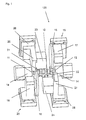
- Fig. 1 is a device 100 for machining purely schematic with regard to those related to the present invention shown the main components that all in a machine frame not shown in the drawing are arranged.
- the workpiece 10, namely a crankshaft, is with its ends 11 and 12 in drivable, rotatable Chuck chucks 13, 14 clamped so that they about their central longitudinal axis is rotatable.
- the disc-shaped high-speed tools are used for machining 15, 16, the corresponding drives 17, 18th are drivable, each drive 17, 18 on a support 19, 20 is mounted, whereby the tool on one axis the workpiece is tracked.
- orthogonal rotary milling cutters in the device 100 21, 22 arranged, which also have corresponding Drives 23, 24 are driven in rotation.
- Any orthogonal milling cutter 21, 22 is on a support with two slides 25, 26; 27, 28 mounted so that a tracking of each orthogonal Rotary milling cutter 21, 22 also possible with the crankshaft rotating is.
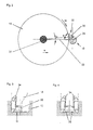
- a high speed tool works like it can be used in the device 100 is purely schematic shown in Fig. 2. It's about machining one outside the center of rotation 29 of the workpiece 10 to perform eccentrically arranged crankshaft thrust bearing 30, the disk-shaped tool 15 about its central axis 31 driven at constant or variable high speed, so that the not shown in the drawing, on the Inserted outer periphery, namely the indexable inserts with a high processing speed Vc be guided past the processing point 32.
- the processing point 32 migrates with the rotation of the workpiece 10 the center of rotation 29 and is from a horizontal plane 33 around deflected an angle ⁇ .
- the tool 15 For tracking the tool 15 this is tracked in the horizontal axis 33 in the direction R, so that with respect to the central axis 31 of the tool 15 machining point 32 deflected by the angle a is always achieved.
- the tool 15 is on the in Horizontal plane 33 lying axis of the tool tracking movement tracked as a function of the angle of rotation ⁇ of the workpiece 10, that after machining at the machining point 32 results in a cylindrical contour. Due to the high cutting speed Vc and the invention low chip thicknesses result in low forces the workpiece 10, which lead to an advantageous result.
- FIG. 3 is in a purely schematic, partially sectioned Partial representation indicated how different insert bodies 34, 35 can be arranged on a tool 15 in order at a processing point 32 of a workpiece 10 a cylindrical Contour, specifically the machining of a tenon Perform crankshaft thrust bearings.
- the insert body creates 34 an undercut, while the insert body 35 den Outside diameter of the pin generated.
- the final contour is thereby generated by two tools that are equipped identically and on two driven tool carriers in the device are located.
- the complete contour (two undercuts and the tenon machining) can be done by a single tool in one cut are generated, then here for the possible wear contour necessarily a reset, axial movement and re-piercing must take place at the appropriate point (Fig. 4).
- a divided tool insert is therefore advantageous provided for a correction by simple Readjustment is easier.
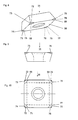
- Insert body 35 as indexable insert 36 has body 37 the indexable insert 36 two opposite one another End faces 38, 39 and four at right angles to one another arranged side surfaces 40, 41, 42, 43.
- the side faces 40, 41, 42, 43 go over the connecting edges at the corner areas 44, 45, 46, 47 one inside the other and on the peripheral edges 48 to 55 in the end faces 38, 39 over.
- the body 37 of the indexable insert 36 has a truncated pyramid Basic shape and the lower peripheral edges 48, 49, 50, 51 are designed as main cutting edges 56, 57, 58, 59.
- each side surface then forms 40, 41, 42, 43 a rake face 40a, 41a, 42a, 43a.
- the cutting inserts described are preferably cubic Boron nitride or polycrystalline cubic boron nitride or a layer of polycrystalline diamond coated. Possibly. an outer layer of aluminum oxide can be applied.
- the relevant coatings are described in detail in the DE 41 26 851 al and DE 41 26 852 A1 described what is hereby expressly referred to.
- inlays from cubic Boron nitride or polycrystalline diamond based on substrate body to be soldered to use. Such inlays will be e.g. in VDI-Z., Vol. 129 (1987) No. 2 - February, pages 64 to 69.
Abstract
Description
Die Erfindung betrifft einen Schneideinsatz und ein Fräsverfahren zur spanenden Bearbeitung von zylindrischen Konturen, von exzentrisch angeordneten zylindrischen Konturen an einem um seine Längsachse rotierenden Werkstück, von zentrisch eingespannten Kurbelwellenhublagern vermittels drehbarer, antreibbarer Werkzeuge, bei dem eine Fertigkontur so erzeugt wird, daß diese entweder bei ausreichender Oberflächenqualität Endmaße aufweist oder noch ein Aufmaß zur Durchführung einer Fertigbearbeitung, wie Schleifen oder Schlichten, aufweist, wobei zur Herstellung der Fertigkontur die mit erfindungsgemäßen Schneideinsätzen, insbesondere Wendeschneidplatten bestückten Werkzeuge nacheinander oder auch gleichzeitig mit dem Werkstück in Eingriff gebracht werden, sowie eine Vorrichtung zur Durchführung des Verfahrens mit mindestens einem Werkzeug mit Schneideinsätzen.The invention relates to a cutting insert and a milling method for machining of cylindrical contours, of eccentric arranged cylindrical contours on one around its longitudinal axis rotating workpiece, of centrally clamped Crankshaft bearings by means of rotatable, drivable Tools in which a finished contour is generated in such a way that these either with sufficient surface quality has or an oversize to carry out a finishing, such as grinding or finishing, wherein for Production of the finished contour using cutting inserts according to the invention, in particular Inserts equipped tools one after the other or brought into engagement with the workpiece at the same time be, as well as a device for performing the method with at least one tool with cutting inserts.
Nach einem bekannten Verfahren erfolgt die Bearbeitung von Kurbelwellenhublagern durch Drehräumen oder Dreh-Drehräumen so, daß die Kurbelwelle exzentrisch gelagert wird, um eine reine Rotation um die Hubzapfenmittelachse zu erzeugen. Bei dieser Lagerung ist auch eine Wangebearbeitung möglich, jedoch hat sich diese Art der Bearbeitung als störanfällig erwiesen, außerdem sind die Spannfutter zur exzentrischen Lagerung der Kurbelwelle teuer. Hinzu kommt, daß die Bearbeitung durch Drehräumen mit einem Werkzeug so erfolgt, daß in einem Arbeitsgang ein Fertigprofil erzeugt wird, das lediglich im Bereich des Zapfens noch einer Fertigbearbeitung durch Schleifen bedarf. Bei dieser Bearbeitung muß für jedes unterschiedliche Kurbelwellenhublager ein unterschiedliches Werkzeug verwandt werden. Crankshaft pin bearings are machined according to a known method through revolving spaces or revolving revolving spaces like that, that the crankshaft is mounted eccentrically to a pure Rotation around the central axis of the crank pin. At this Storage is also possible for honeycomb processing, however this type of processing proved to be prone to failure, in addition, the chucks are for eccentric storage of the Crankshaft expensive. Added to this is the fact that machining is done by turning done with a tool so that in one operation a finished profile is generated that only in the area of Tenon still needs finishing by grinding. During this processing, different crankshaft thrust bearings must be used for each a different tool can be used.
Verfahrensgemäß werden dabei nach dem Stand der Technik Werkzeugträger eingesetzt, wobei auf dem Werkzeugträger mehrere Schneideinsatztypen Verwendung finden.According to the method, tool carriers are used according to the prior art used, with several on the tool carrier Find insert types.
Die US-A-2 290 324 beschreibt ein Verfahren zur spanenden Bearbeitung von Kurbelwellen, die beidseitig eingespannt und rotierend gegenüber den Fräswerkzeugen bewegt werden.US-A-2 290 324 describes a machining process of crankshafts that are clamped on both sides and rotating be moved relative to the milling tools.
Aus der EP 0372717 A2 ist ein Innenfräser bekannt, der das zu fräsende Hublager umläuft.An internal milling cutter is known from EP 0372717 A2, which also allows this milling pin bearing rotates.
Die US-A-3 279 034 beschreibt einen Fräser mit Schneideinsätzen, deren Spanfläche konvex gewölbt ist. US-A-3 279 034 describes a milling cutter with cutting inserts, whose rake face is convex.
Mittels dieser Werkzeugträger werden die Wangen und Unterstiche zu beiden Seiten der Kontur und der Zapfen über die gesamte Breite in jeweils einem Schnittvorgang gefertigt. Pro Fertigkontur wird somit ein Werkzeugträger benötigt.The cheeks and undercuts are created using these tool carriers on both sides of the contour and the spigot over the entire Width made in one cut. Per finished contour a tool carrier is therefore required.
Nach einer speziellen Maßgabe des Verfahrens ist vorgesehen, daß in einem ersten Schritt die Bearbeitung der Hublagerwangen und in einem zweiten Bearbeitungsschritt die Zapfenbearbeitung zur Erzeugung des Zapfendurchmessers und des Unterstiches erfolgt.According to a special provision of the method, that in a first step the machining of the pin bearing cheeks and in a second processing step, the tenon machining to generate the pin diameter and the undercut he follows.
Nach einem zweiten bekannten Verfahren wird die Kurbelwelle eingespannt und mit einem Innenfräser bearbeitet, der in einem Umlauf um das Hublager bewegt wird. Nachteile dieser Bearbeitung sind große Wege und große bewegte Massen, so daß ein Hochgeschwindigkeitsfräsen nicht möglich ist.According to a second known method, the crankshaft clamped and machined with an internal milling cutter that works in one Circulation around the pin bearing is moved. Disadvantages of this editing are large paths and large moving masses, so that a high-speed milling not possible.
Ein Fräskopf zur Erzeugung eines Lagerprofiles an einer Kurbelwelle
in einem Arbeitsgang ist aus der DE 38 24 348 A1 bekannt.
Der hierzu vorgeschlagene Fräskopf in Scheiben- oder Wirbelbauart
zum Bearbeiten von Kurbelwellen, die als fräsend zu bearbeitende
Oberflächen eine parallel zur Fräskopfachse liegende
Zylinderoberfläche enthalten, die vorzugsweise beidseitig über
eine rotationssymmetrisch geformte Kehlfläche in eine annähernd
achsensenkrechte Fläche übergeht, mit an dem äußeren oder inneren
Schneidumfang des Fräskopfes in Halterung angebrachten
Sätzen von Wendeschneidplatten, ist so ausgebildet, daß mehrere
Sätze von Wendeschneidplatten gleichmäßig am Schneidenumfang
des Fräskopfes angeordnet sind, daß jeder Satz von Wendeschneidplatten
vollständig die Meridiankontur der zu bearbeitenden
Oberfläche des Werkstückes überdeckt und daß innerhalb
eines Satzes von Wendeschneidplatten für jede bestimmte zu
bearbeitende Oberflächenpartie des Werkstückes mindestens eine
Wendeschneidplatte vorgesehen sind, ist mit speziellen Wendeschneidplatten
so bestückt, daß alle zu erstellenden Kantenflächen
gleichzeitig bearbeitet werden. A milling head for creating a bearing profile on a crankshaft
in one operation is known from
Ein als Wendeschneidplatte zu bezeichnender Schneideinsatz, der
einen polygonalen flächigen Körper mit mindestens einer Hauptschneidkante,
einer Span- und einer Freifläche aufweist, ist
aus der DE 44 00 570 bekannt.A cutting insert to be called an indexable insert, the
a polygonal flat body with at least one main cutting edge,
has a chip and a free surface
known from
Die EP 0505574 A1 beschreibt einen in der Grundform quadratischen Schneideinsatz, der in Schneideckennähe abgeschrägte und zurückgesetzte ebene Freiflächenabschnitte aufweist, wodurch an einem Schneidende eine negative Fase gebildet wird.EP 0505574 A1 describes one in its basic form square cutting insert that is close to the cutting corner bevelled and recessed flat open space sections has a negative chamfer at one cutting end is formed.
Ein Fräsen mit hoher Schnittgeschwindigkeit von über
160 m/min konnte, obwohl es wirtschaftliche Vorteile infolge
verkürzter Bearbeitungszeiten verspricht, beim Zerspanen
zylindrischer Konturen, insbesondere beim Kurbelwellenfräsen
bis heute nicht angewendet werden, weil bei den bis heute
verwandten Werkzeugen
Ausgehend von diesem Stand der Technik ist es Aufgabe der Erfindung, die spanende Bearbeitung zylindrischer Konturen, insbesondere die Kurbelwellenbearbeitung dahingehend zu verbessern, daß bei Beibehaltung oder Steigerung der Oberflächenqualität und bei Beibehaltung oder Steigerung der Maßgenauigkeit eine Reduzierung der Bearbeitungszeiten erreicht wird, wobei gleichzeitig die Gesamtwirtschaftlichkeit erhöht werden soll.Based on this state of the art, it is the task of Invention, the machining of cylindrical contours, in particular to improve crankshaft machining that while maintaining or increasing the surface quality and while maintaining or increasing dimensional accuracy a reduction in processing times is achieved, whereby at the same time, the overall economy should be increased.
Zur Lösung dieser Aufgabe wird das im Patentanspruch 1 angegebene Verfahren vorgeschlagen.To solve this problem, that specified in claim 1 Proposed procedure.
Unter dem sogenannten erfindungsgemäßen Hochgeschwindigkeitsfräsen,
d.h. einer spanabhebenden Bearbeitung mit einem Fräser
(Außenfräser), wird die Bearbeitung
Durch Hochgeschwindigkeitsfräsen können so gute Oberflächenqualitäten erzeugt werden, daß das Vorschleifen oder zusätzliche Vorbehandlungen vor der Wärmebehandlung als zusätzlicher Arbeitsvorgang vollständig entfallen kann.High-speed milling can produce good surface qualities generated that the pre-grinding or additional Pretreatments before the heat treatment as an additional Work process can be completely eliminated.
Zumindest ein Teil der Schneideinsätze, vorzugsweise alle Schneideinsätze weisen einen positiven Spanwinkel auf. Die Schneideinsatzeinstellung zum Werkstück wird dergestalt vorgenommen, daß der effektive Spanwinkel zwischen -5° und +15°, vorzugsweise -5° bis +5°, und/oder ein positiver axialer Spanwinkel (Rückspanwinkel γp) bis zu 10° gewählt wird. At least some of the cutting inserts, preferably all cutting inserts, have a positive rake angle. The cutting insert setting for the workpiece is carried out in such a way that the effective rake angle between -5 ° and + 15 °, preferably -5 ° to + 5 °, and / or a positive axial rake angle (rake angle γ p ) up to 10 ° is selected.
Das erfindungsgemäße Verfahren ist eine Bearbeitungsweise, die sich besonders zur spanenden Bearbeitung von exzentrisch angeordneten zylindrischen Konturen, insbesondere speziell von Kurbelwellenhublagern, bei zentrisch eingespanntem Werkstück eignet. Daher können sowohl die problematisch zu fertigenden Hublager als auch die Hauptlager auf der gleichen Vorrichtung bzw. bei Reihen- oder Parallelschaltung von mehreren Vorrichtungen auf gleichartigen Vorrichtungen gefertigt werden.The method according to the invention is a processing mode that are particularly suitable for machining eccentrically arranged cylindrical contours, especially of crankshaft thrust bearings, suitable for a centrally clamped workpiece. Therefore, both the problematic pin bearings can be manufactured as well as the main bearings on the same device or with series or parallel connection of several devices be manufactured on similar devices.
Die Herstellung der Fertigkontur, die als solche bereits Endmaße aufweist oder noch ein Aufmaß, das durch Schleifen oder Schlichten abgetragen werden kann, mit Werkzeugen, die mit Schneideinsätzen bestückt nacheinander oder auch gleichzeitig mit dem Werkstück in Eingriff gebracht werden, wird auch als sogenannte Schnitteilung bezeichnet. Hierunter versteht man beispielsweise die Aufteilung der Bearbeitung der Wangen einer Kurbelwelle und die Bearbeitung des Unterstiches und des Zapfens einer Kurbelwelle oder die Herstellung einer halben Kurbelwellen-Wangenkontur mit einem Unterstich und einem Durchmesseranteil mit einem ersten Werkzeug und die Herstellung eines zweiten Unterstiches und des restlichen Durchmesseranteiles mit einem zweiten Werkzeug. Durch eine solche Aufteilung bzw. Bearbeitung mit geteiltem Werkzeug ist es möglich, die Lagerbreite in bestimmten Grenzen zu variieren, d.h. auch unterschiedlich breite Lager mit einem rechten und einem linken Werkzeug zu erzeugen und/oder Veränderungen der Lagerbreite infolge eines Werkzeug-Verschleißes durch Nachstellung mittels einer NC-Steuerung zu korrigieren.The production of the finished contour, which as such already has final dimensions has or an oversize that by grinding or Finishing can be done away with with tools Cutting inserts loaded one after the other or simultaneously engaged with the workpiece is also called called so-called cut division. This means for example the division of the processing of the cheeks one Crankshaft and the processing of the undercut and the pin a crankshaft or the production of a half crankshaft cheek contour with an undercut and a proportion of diameter with a first tool and making one second under stitch and the remaining diameter portion a second tool. Through such a division or processing with split tool it is possible to change the bearing width vary within certain limits, i.e. also different wide bearings with a right and a left tool generate and / or changes in bearing width as a result of Tool wear through adjustment using a Correct NC control.
Die Bearbeitung erfolgt dabei so, daß das Werkzeug mit konstanter oder variabler hoher Drehzahl angetrieben wird, so daß eine Hochgeschwindigkeitszerspanung erreicht wird. Vorzugsweise wird bei variabler Drehzahl diese schrittweise linear geändert. Dadurch können die Vorteile von Hochgeschwindigkeitsfräsern jetzt auch bei der Kurbelwellenbearbeitung erreicht werden, nämlich Steigerung der Oberflächenqualität, Steigerung der Maßgenauigkeit und Reduzierung der Bearbeitungszeiten. Für die Anwendung des Hochgeschwindigkeitsfräsens war es nötig, verschiedene Vorurteile und Probleme zu überwinden. So war die Verwendung der bereits bekannten Schneideinsätze in bestehendem Werkzeug auf bekannten Vorrichtungen nicht möglich, da sich zu hohe Kräfte und eine zu hohe Erwärmung für die Werkzeuge ergab. Bei labilen Kurbelwellen tritt ggf. eine große Schwingungsneigung auf. Dieser kann dadurch entgegengewirkt werden, daß eine Aufteilung in mindestens zwei Fräsvorgänge vorgenommen wird. Durch die Aufteilung werden verschiedene Vorteile realisiert. Während bei der Verwendung eines einzigen Werkzeuges axiale und radiale Anregungen auftreten, wodurch sich eine starke Schwingungsneigung ergab, kann die Aufteilung jetzt so gewählt werden, wo diese weitgehend vermieden wird. Außerdem ist es möglich geworden, insbesondere bei NC-Steuerungen eine Nachstellung durchzuführen, so daß ein Verschleiß am Werkzeug bzw. an dem oder den Schneideinsätzen ausgeglichen werden kann. Außerdem kann die Bemaßung beliebig gewählt werden, so daß die Fertigung unterschiedlicher Kurbelwellen auf der gleichen Fertigungsstraße jetzt problemlos möglich ist. The machining is done so that the tool with constant or variable high speed is driven so that high-speed machining is achieved. Preferably If the speed is variable, this is gradually changed linearly. This can take advantage of high speed milling cutters can now also be achieved in crankshaft machining, namely increasing the surface quality, increasing the Dimensional accuracy and reduction of processing times. For the Application of high speed milling it was necessary to overcome various prejudices and problems. It was like that Use of the already known cutting inserts in existing Tool on known devices not possible, because too high forces and excessive heating for the tools resulted. With unstable crankshafts, there may be a great tendency to vibrate on. This can be counteracted by the fact that a It is divided into at least two milling processes. The division realizes various advantages. While using a single tool axial and Radial excitations occur, causing a strong tendency to vibrate the division can now be chosen so where this is largely avoided. It is also possible become an adjustment, especially with NC controls perform so that wear on the tool or the cutting insert or inserts can be compensated. Moreover the dimensions can be chosen arbitrarily, so that the production different crankshafts on the same production line is now easily possible.
Bei der erfindungsgemäßen Vorgehensweise mit zwei Werkzeugen, die als "geteiltes Werkzeug" bezeichnet werden können, ergeben sich verschiedene Vorteile, denn es können unterschiedliche Konturen mit den gleichen Werkzeugen erzeugt werden und es kann auch eine Korrektur zum Ausgleich eines Verschleißes an den Schneideinsätzen, insbesondere den Wendeschneidplatten erfolgen.In the procedure according to the invention with two tools, which can be called a "shared tool" different benefits because there can be different Contours can be created with the same tools and it can also a correction to compensate for wear on the Cutting inserts, especially the indexable inserts.
Erfindungsgemäß handelt es sich bei den Werkzeugen um mit entsprechenden Schneideinsätzen versehene Hochgeschwindigkeitsfräser. Gemäß einer speziellen Ausführungsform sind die Schneideinsätze so ausgebildet und angeordnet, daß in einem Einstichvorgang jeweils etwa die Hälfte der Fertigkontur des Zapfens erzeugbar ist. Bevorzugterweise wird hierzu ein Scheibenfräser verwendet.According to the invention, the tools are with corresponding ones High speed milling cutters. According to a special embodiment, the cutting inserts designed and arranged so that in one puncture each about half of the finished contour of the pin can be generated. A side milling cutter is preferably used for this used.
Nach einer besonderen Ausführungsform der Erfindung sind dabei auf dem Werkzeug Wendeschneidplatten zur Wangenbearbeitung und auf einem anderen Werkzeug Wendeschneidplatten zur Zapfenbearbeitung und für den Unterstich angebracht.According to a special embodiment of the invention on the tool indexable inserts for cheek machining and on another tool indexable inserts for tenon machining and attached for the understitch.
Nach einer weiteren, besonders vorteilhaften Ausführungsform der Erfindung werden die Schneideinsätze auf mindestens zwei Werkzeugträger so verteilt, daß ein erstes Werkzeug die rechte Seite der Kontur einschließlich der Hälfte des Zapfens und ein zweites Werkzeug die linke Seite der Kontur einschließlich der Hälfte des Zapfens bearbeitet.According to a further, particularly advantageous embodiment the cutting inserts on at least two of the invention Tool carrier distributed so that a first tool the right Side of the contour including half of the tenon and one second tool the left side of the contour including the Half of the tenon machined.
Zur Korrektur des Überschnittes wird ein erfindungsgemäß speziell gestalteter Schneideinsatz verwendet, der nachstehend noch in seiner Gestaltung beschrieben ist. Unter einem Überschnitt ist der Überdeckungsbereich in einer bearbeiteten Werkzeugfläche zu verstehen, der sich durch Bearbeitung mittels zweier Schneidplattenreihen eines Werkzeuges oder zweier Werkzeuge ergibt. Durch Fertigungsungenauigkeiten oder - bei geteiltem Werkzeug - durch Positionierungsungenauigkeiten der Bearbeitungsmaschine entsteht ein Höhenversatz zweier Schneidplatten bzw. Schneidplattenreihen. Hierdurch ergibt sich in dem Überdeckungsbereich ein unerwünschter scharfkantiger Absatz. Um diesen zu verhindern, besitzen die Spanflächen der vorzugsweise verwendeten Schneideinsätze im Bereich der eine Schneidecke bildenden Hauptschneidkante eine Abflachung oder Einziehung, die sich in den Bereich beider benachbarter Hauptschneidkanten erstreckt. Die Verwendung solcher Schneideinsätze ermöglicht die Fertigung äußerst sanfter Übergänge im Überdeckungsbereich, die sich sowohl meßbar als auch optisch im Sinne einer optimalen Oberfläche, beispielsweise der Zapfenoberfläche eines Kurbelwellenhubzapfens auswirkt.According to the invention, a special one is used to correct the overcut designed cutting insert used below is still described in its design. Under an overcut is the coverage area in a machined tool surface to understand who is working through two rows of inserts of one tool or two tools results. Through manufacturing inaccuracies or - at shared tool - due to positioning inaccuracies of the Processing machine creates a height offset of two cutting inserts or rows of inserts. This results in the Coverage area an undesirable sharp-edged paragraph. Around To prevent this, the rake faces preferably have used cutting inserts in the area of a cutting corner main cutting edge forming a flattening or indentation, which are in the area of both adjacent main cutting edges extends. The use of such cutting inserts enables the production of extremely smooth transitions in the coverage area, which are both measurable and optically in the sense of an optimal Surface, for example the pin surface of a crankshaft crank pin affects.
Durch die Schnitteilung, d.h. die Aufteilung der Werkstückbearbeitung in mindestens zwei Bearbeitungen, wird erreicht, daß während des Fräsvorganges weniger Schneiden gleichzeitig im Eingriff sind, wodurch die Kräfte auf das Werkzeug und damit die Schwingungsanregung vermindert wird.Through the cut division, i.e. the division of workpiece processing in at least two edits, it is achieved that less cutting at the same time during the milling process Are engaging, reducing the forces on the tool and therefore the vibration excitation is reduced.
Durch die Verwendung eines Schneideinsatzes mit positivem Schneidwinkel wird die Zerspanungstemperatur gesenkt, die auf das Werkzeug wirkenden Kräfte und damit die Schwingungsanregung weiter vermindert.By using a cutting insert with positive Cutting angle, the machining temperature is lowered to forces acting on the tool and thus the vibration excitation further decreased.
Ein weiterer Vorteil des erfindungsgemäßen Verfahrens besteht darin, daß im Falle der Aufteilung der Schneideinsätze, insbesondere der Wendeschneidplatten zur Herstellung rechter und linker Hälften der Kontur, der Verschleiß an den Schneideinsätzen durch Verfahren des Werkzeuges in axialer oder radialer Richtung ausgeglichen werden kann. Another advantage of the method according to the invention is in that in the case of the division of the cutting inserts, in particular of indexable inserts for the production of right and left half of the contour, the wear on the cutting inserts by moving the tool axially or radially Direction can be compensated.
Würde die Komplettkontur durch ein einziges Werkzeug hergestellt, müßte mindestens eine Wendeschneidplatte zurückgesetzt, d.h. manuell versetzt werden, um den Verschleiß auf beiden Seiten auszugleichen.If the complete contour were produced using a single tool, would have to reset at least one insert, i.e. manually offset to wear on both sides balance.
Eine weitere Ausgestaltung der Vorrichtung sieht vor, daß mindestens ein Werkzeugträger ein orthogonaler Drehfräser ist.A further embodiment of the device provides that at least a tool carrier is an orthogonal milling cutter.
Die Vorrichtung zur Durchführung des erfindungsgemäßen Zerspanungsverfahrens soll pro Kurbelwellenhublager einen Support aufweisen, der für Fräsoperationen mit mindestens einer nachführbaren Achse und für orthogonales Drehfräsen mit zwei nachführbaren Achsen ausgerüstet ist, damit das Werkzeug in Abhängigkeit vom Drehwinkel des Werkstückes so nachgeführt werden kann, daß sich nach der spanenden Bearbeitung der exzentrisch angeordneten Kurbelwellenhublager eine zylindrische Korrektur ergibt und die oben beschriebenen Korrekturvorgänge zum Ausgleich des Wendeschneidplattenverschleißes durchgeführt werden.The device for carrying out the machining process according to the invention one support per crankshaft thrust bearing have the for milling operations with at least one trackable Axis and for orthogonal rotary milling with two trackable Axes is equipped so that the tool is dependent are tracked by the angle of rotation of the workpiece can that after machining the eccentric arranged crankshaft thrust bearing a cylindrical correction results and the correction processes described above to compensate of indexable insert wear.
Die spezielle Vorgehensweise besteht darin, daß das Werkzeug auf einer Achse in Abhängigkeit vom Drehwinkel des Werkstückes so nachgeführt wird, daß sich nach der spanenden Bearbeitung eine zylndrische Kontur ergibt. Aufgrund der hohen Schnittgeschwindigkeit und der geringen Spanungsdicken resultieren geringe Kräfte auf das Werkstück, die das Zerspanen auf dem labilen Werkstück begünstigen. Gleichzeitig ergeben sich durch die geringeren Vorschubwerte und die hohen Schnittgeschwindigkeiten bessere Oberflächenqualitäten, als diese bisher durch vergleichbare Verfahren erzielt werden konnten.The special procedure is that the tool on an axis depending on the angle of rotation of the workpiece is tracked so that after machining results in a cylindrical contour. Because of the high cutting speed and the low chip thicknesses result low forces on the workpiece, which means machining on the favor unstable workpiece. Simultaneously arise from the lower feed rates and the high cutting speeds better surface qualities than these so far comparable procedures could be achieved.
Dadurch, daß der Gesamtumfang des Werkzeuges in bezug auf die eingesetzte Schnittbogenlänge groß bemessen ist, wird erreicht, daß jeder einzelne Schneideinsatz in bezug auf den Drehwinkel des Werkzeuges nur kurz zum Einsatz kommt, so daß eine lange Abkühlzeit gegeben ist. Außerdem ist es möglich, eine große Anzahl von Schneideinsätzen anzuordnen, so daß hohe Standzeiten und Einsatzdauern jedes Werkzeuges erreicht werden können. The fact that the total scope of the tool in relation to the the length of the cut sheet used is long, that every single cutting insert in relation to the angle of rotation of the tool is used only briefly, so that a long Cooling time is given. It is also possible to have a large one Arrange number of cutting inserts, so that long service life and service life of each tool can be achieved.
Besonders vorteilhaft ist es, wenn verfahrensgemäß das Hochgeschwindigkeitsfräsen und das orthogonale Drehfräsen kombiniert werden, da hierdurch die Vorteile beider Bearbeitungsarten optimal miteinander kombiniert werden können. Vorzugsweise weist eine Vorrichtung zur Durchführung des Verfahrens hierzu mehrere Supporte auf, wobei das Werkzeug zum orthogonalen Drehfräsen auf zwei Schlitten gelagert ist, um das Werkzeug dem Werkstück nachzuführen.It is particularly advantageous if, in accordance with the method, high-speed milling and combines orthogonal turning milling because this gives the advantages of both types of processing can be optimally combined. Preferably has a device for performing the method for this several supports, using the tool for orthogonal turning is mounted on two slides to the tool Track workpiece.
Die Aufteilung des Werkzeuges und die Durchführung von mindestens
zwei Fräsvorgängen führt dazu, daß bevorzugterweise die
Kontur durch zwei Werkzeuge erzeugt wird, die sich auf zwei
angetriebenen Werkzeugträgern in der Vorrichtung befinden. Die
Vorteile eines geteilten Werkzeugkonzeptes gegenüber der früheren
Erstellung der Kontur als Komplettkontur durch ein einziges
Werkzeug in einem Schnittvorgang bestehen darin, daß
Eine erfindungsgemäße Vorrichtung ist daher so ausgebildet, daß der Schnittvorgang zur Herstellung der Fertigkontur in mindestens zwei Schnittvorgänge aufgeteilt wird (Schnitteilung), wobei die mit Wendeschneidplatten bestückten Werkzeugträger nacheinander in Eingriff gebracht werden und die Werkzeugträger ausschließlich mit Wendeschneidplatten bestückt sind, die einen positivem Spanwinkel aufweisen, wobei die Vorrichtung mindestens zwei mit Schneideinsätzen versehene Werkzeuge aufweist, wobei jedes Werkzeug ein mit entsprechenden Schneideinsätzen versehener Hochgeschwindigkeitsfräser nach Anspruch 5 ist. Bevorzugterweise wird als Werkzeug ein Scheibenfräser verwendet, der mit entsprechenden Wendeschneidplatten versehen ist, die ein Hochgeschwindigkeitsfräsen ermöglichen. Mit einem orthogonalen Drehfräser ist eine optimale Zapfenbearbeitung durchführbar.A device according to the invention is therefore designed such that the cutting process to produce the finished contour in at least two cutting processes are divided (cutting division), the tool carriers equipped with indexable inserts be engaged one after the other and the tool carrier are only equipped with indexable inserts that one have positive rake angle, the device at least has two tools provided with cutting inserts, each tool one with appropriate cutting inserts provided high speed milling cutter according to claim 5. A side milling cutter is preferably used as the tool, which is provided with appropriate indexable inserts, which enable high-speed milling. With a orthogonal milling cutter is an optimal tenoning feasible.
Für die Durchführung eines solchen Verfahrens hat es sich als
besonders vorteilhaft erwiesen, wenn ein Schneideinsatz nach
Anspruch 9 verwendet wird. Vorzugsweise Weiterbildungen dieses
Schneideinsatzes werden in den Ansprüchen 10 bis 15 beschrieben.
Der Schneideinsatz weist einen an sich bekannten polygonalen
flächigen Körper auf und ist vorzugsweise so gestaltet, daß
sich bei seinem Einsatz am Werkstück ein positiver Schneidwinkel
ergibt. Durch den positiven Schneidwinkel wird die Zerspanungstemperatur
gesenkt, ferner werden die auf das Werkzeug
wirkenden Kräfte und damit die Schwingungsanregung minimiert.
Hierzu erfolgt die Gestaltung so, daß die Summe des Freiwinkels
und des Keilwinkels zwischen 85° und 95° ergibt, woraus sich
ein effektiver Spanwinkel γf zwischen -5° und +5° ergibt. Ggf.
kann der Spanwinkel auch bis zu 15° betragen. Der Rückspanwinkel
γp wird positiv gewählt und soll maximal 10° betragen. Bei
tangentialer Einbaulage des Schneidkörpers wird die jeweils im
Anspruch 10 definierte Freifläche zur wirksamen Spanfläche,
während umgekehrt die Spanfläche als wirksame Freifläche verwendet
wird. Hieraus ergibt sich in entsprechender Weise, daß
die wirksame Freifläche die vorbeschriebenen Abflachungen oder
Einziehungen aufweist. Je nach Funktion sind somit pro Schneideinsatz
zwei oder auch vier Abflachungen bzw. Einziehungen möglich. For carrying out such a method, it has proven to be particularly advantageous if a cutting insert according to claim 9 is used. Further developments of this cutting insert are preferably described in
Es hat sich dabei gezeigt, daß die Breite des Schneidkörpers bzw. die Breite der einzusetzenden Hauptschneidkante vorteilhafterweise etwa größer gleich der Hälfte der Breite der zu bearbeitenden Zapfenbreite gewählt wird, so daß durch den nacheinandergeschalteten Einsatz von zwei Schneidkörpern eine optimale Zapfenoberfläche geschaffen wird.It has been shown that the width of the cutting body or the width of the main cutting edge to be used advantageously about greater than or equal to half the width of the machining pin width is selected so that by the successive use of two cutting elements one optimal cone surface is created.
Insbesondere um den Überschneidungsbereich bei dem Einsatz von zwei Schneideinsätzen meßbar und optisch so zu optimieren, daß sich eine nahezu völlig gleichmäßige Zapfenoberfläche ergibt, wird ein spezieller Schneideinsatz vorgeschlagen, bei dem vorgesehen ist, daß für mindestens ein Werkzeug ein Support vorgesehen ist, der eine Verfahrbarkeit des Werkzeuges in zwei zueinander senkrechten Richtungen ermöglicht. Diese spezielle Ausbildung ist optimal an den Einsatzzweck angepaßt. Besonders vorteilhaft ist es dabei, wenn die Spanfläche im Bereich der Schneidkörperecke eine Abflachung oder Einziehung aufweist, d.h., daß bei der Fertigung eines solchen Schneideinsatzes im Bereich der Schneidkörperecke eine Fläche angebracht wird, die dazu führt, daß die Schneidecke gegenüber der Hauptschneidkante zurückliegt. Dies führt zu einem weicheren Übergang im Überschneidungsbereich der Einsatzbereiche von zwei derartigen Einsatzkörpern, so daß bei der Untersuchung, beispielsweise der Zapfenoberfläche eines Kurbelwellenhubzapfens sowohl meßbar als auch optisch eine optimale Oberfläche erzielt wird.In particular, the area of overlap when using two cutting inserts measurable and optically optimized so that there is an almost completely uniform pin surface, A special cutting insert is proposed in which is that support is provided for at least one tool which is a movability of the tool in two directions perpendicular to each other. This special Training is optimally adapted to the application. Especially It is advantageous if the rake face in the area of Cutting edge has a flattening or indentation, i.e. that in the manufacture of such a cutting insert in Area of the cutter corner is attached to a surface causes the cutting corner opposite the main cutting edge back. This leads to a smoother transition in the overlap area the areas of application of two such insert bodies, so that in the investigation, for example the Pin surface of a crankshaft crank pin both measurable and an optimal surface is also achieved optically.
Um die Standzeiten eines solchen Schneideinsatzes, der insbesondere im Bereich der Schneidkörperecke bzw. der Schneidkörperecken besonders hoch belastet ist, weiter zu erhöhen, ist vorgesehen, daß im Bereich der Schneidecken Abflachungen oder Einziehungen als Stützflächen angebracht werden. Stabilisierung eignet sich insbesondere für solche Schneidplatten, die in einem sogenannten geteilten Werkzeug zur Schnitteilung zum Einsatz kommen. Die durchmessererzeugende Schneidplatte des ersten Werkzeuges schneidet hiermit der durch positive Spanwinkel stark gefährdeten Schneidecke 90° ins volle Material des Werkstückes. Durch die Anbringung von Stützflächen an den Freiflächen der Schneidecken kann im dortigen Bereich eine zusätzliche Stabilisierung erfolgen, ohne auf die positive Spanformgeometrie und/oder die vier Schneiden der Schneidplatte zu verzichten.The service life of such a cutting insert, in particular in the area of the cutting body corners or the cutting body corners is particularly high, is to increase further provided that in the area of the cutting corners flattening or Indentations can be attached as support surfaces. stabilization is particularly suitable for cutting inserts that are in a so-called split tool for cutting division come. The diameter-producing insert of the first This tool cuts through positive rake angles highly vulnerable cutting corner 90 ° into the full material of the workpiece. By attaching support surfaces to the open spaces the cutting corners can have an additional area there Stabilization is done without relying on the positive chip shape geometry and / or to dispense with the four cutting edges of the cutting insert.
Weitere bevorzugte Verfahrensmaßnahmen, Ausgestaltungen der Vorrichtung und Ausführungsform des Schneideinsatzes sind in den Unteransprüchen angegeben.Further preferred procedural measures, configurations of the Device and embodiment of the cutting insert are in specified in the subclaims.
In der Zeichnung ist die Erfindung anhand von Ausführungsbeispielen dargestellt. Es zeigen
- Fig. 1
- in einer schaubildlichen Ansicht eine erfindungsgemäße Vorrichtung,
- Fig. 2
- in einer schematischen Darstellung die verfahrensgemäße Bearbeitungsweise,
- Fig. 3
- in einer schematischen Darstelllung die Arbeitsweise von zwei Schneideinsätzen,
- Fig. 4
- die Arbeitsweise von zwei Schneideinsätzen,
- Fig. 5 und 6
- in schaubildlichen Darstellungen einen erfindungsgemäßen Schneideinsatz,
- Fig. 7
- eine Detaildarstellung des Schneideinsatzes gemäß Fig. 6 und
- Fig. 8
bis 10 - in unterschiedlichen Ansichten den erfindungsgemäßen Schneideinsatz.
- Fig. 1
- A device according to the invention in a perspective view,
- Fig. 2
- in a schematic representation the method of processing,
- Fig. 3
- a schematic representation of the operation of two cutting inserts,
- Fig. 4
- the operation of two cutting inserts,
- 5 and 6
- a cutting insert according to the invention in diagrammatic representations,
- Fig. 7
- a detailed view of the cutting insert according to FIG. 6 and
- 8 to 10
- the cutting insert according to the invention in different views.
In Fig. 1 ist eine Vorrichtung 100 zur spanenden Bearbeitung
rein schematisch im Hinblick auf die im Zusammenhang mit der
vorliegenden Erfindung wichtigsten Bauteile dargestellt, die
alle in einem in der Zeichnung nicht dargestellten Maschinengestell
angeordnet sind. Das Werkstück 10, nämlich eine Kurbelwelle,
ist mit ihren Enden 11 und 12 in antreibbaren, drehbaren
Einspanfuttern 13, 14 so eingespannt, daß sie um ihre Mittellängsachse
drehbar ist.In Fig. 1 is a
Zur Bearbeitung dienen die scheibenförmigen Hochgeschwindigkeitswerkzeuge
15, 16, die über entsprechende Antriebe 17, 18
antreibbar sind, wobei jeder Antrieb 17, 18 auf einem Support
19, 20 gelagert ist, wodurch das Werkzeug auf einer Achse
dem Werkstück nachgeführt wird.The disc-shaped high-speed tools are used for machining
15, 16, the corresponding drives 17, 18th
are drivable, each drive 17, 18 on a
Weiterhin sind in der Vorrichtung 100 zwei orthognonale Drehfräser
21, 22 angeordnet, die ebenfalls über entsprechende
Antriebe 23, 24 drehantreibbar sind. Jeder orthogonale Drehfräser
21, 22 ist auf einem Support mit jeweils zwei Schlitten 25,
26; 27, 28 gelagert, so daß eine Nachführung jedes orthogonalen
Drehfräsers 21, 22 auch bei sich drehender Kurbelwelle möglich
ist.Furthermore, there are two orthognonal rotary milling cutters in the
Mit der dargestellten Vorrichtung ist die gleichzeitige Bearbeitung von vier Hublagerstellen möglich.With the device shown is the simultaneous processing possible from four hub bearings.
Die Arbeitsweise eines Hochgeschwindigkeitswerkzeuges, wie es
in der Vorrichtung 100 Verwendung finden kann, ist rein schematisch
in Fig. 2 dargestellt. Um nämlich eine spanende Bearbeitung
eines außerhalb des Drehzentrums 29 des Werkstückes 10
exzentrisch angeordneten Kurbelwellenhublagers 30 durchzuführen,
wird das scheibenförmige Werkzeug 15 um seine Mittelachse
31 mit konstanter oder variabler hoher Drehzahl angetrieben,
so daß die in der Zeichnung nicht dargestellten, auf dem
Außenumfang angeordneten Einsatzkörper, nämlich die Wendeschneidplatten
mit einer hohen Bearbeitungsgeschwindigkeit Vc
an der Bearbeitungsstelle 32 vorbeigeführt werden. Die Bearbeitungsstelle
32 wandert mit der Drehung des Werkstückes 10 um
das Drehzentrum 29 und wird aus einer Horizontalebene 33 um
einen Winkel β ausgelenkt. Zur Nachführung des Werkzeuges 15
wird dieses in der Horizontalachse 33 in Richtung R nachgeführt,
so daß die im Hinblick auf die Mittelachse 31 des Werkzeuges
15 um den Winkel a ausgelenkte Bearbeitungsstelle 32
immer erreicht wird. Das Werkzeug 15 wird dabei auf der in der
Horizontalebene 33 liegenden Achse der Werkzeugnachführbewegung
in Abhängigkeit vom Drehwinkel β des Werkstückes 10 so nachgeführt,
daß sich nach der spanenden Bearbeitung an der Bearbeitungsstelle
32 eine zylindrische Kontur ergibt. Aufgrund der
hohen Schnittgeschwindigkeit Vc und der erfindungsgemäß vorgesehenen
geringen Spanungsdicken resultieren geringe Kräfte auf
das Werkstück 10, die zu einem vorteilhaften Ergebnis führen.How a high speed tool works like it
can be used in the
In Fig. 3 ist in einer rein schematischen, teilweise geschnittenen
Teildarstellung angedeutet, wie unterschiedliche Einsatzkörper
34, 35 auf einem Werkzeug 15 angeordnet sein können, um
an einer Bearbeitungsstelle 32 eines Werkstückes 10 eine zylindrische
Kontur, nämlich speziell die Zapfenbearbeitung eines
Kurbelwellenhublagers durchzuführen. Dabei erzeugt der Einsatzkörper
34 einen Unterstich, während der Einsatzkörper 35 den
Außendurchmesser des Zapfens erzeugt. Die Endkontur wird dabei
durch zwei Werkzeuge erzeugt, die identisch bestückt sind und
sich aufzwei angetriebenen Werkzeugträgern in der Vorrichtung
befinden.3 is in a purely schematic, partially sectioned
Partial representation indicated how
Die Komplettkontur (zwei Unterstiche und die Zapfenbearbeitung) kann durch ein einziges Werkzeug in einem Schnittvorgang erzeugt werden, wobei hier dann zur eventuellen Verschleißkontur notwendigerweise ein Zurücksetzen, axiales Verfahren und erneutes Einstechen an entsprechender Stelle erfolgen muß (Fig. 4). Vorteilhafterweise wird daher ein aufgeteilter Werkzeugeinsatz vorgesehen, bei dem eine Korrektur durch einfaches Nachstellen leichter möglich ist. The complete contour (two undercuts and the tenon machining) can be done by a single tool in one cut are generated, then here for the possible wear contour necessarily a reset, axial movement and re-piercing must take place at the appropriate point (Fig. 4). A divided tool insert is therefore advantageous provided for a correction by simple Readjustment is easier.
Wenn die Erzeugung der Zapfenbreite mit zwei Werkzeugen realisiert
wird, so sollte der Formfehler im überschnitt, der möglicherweise
durch Rundlauffehler des Werkzeuges oder durch einen
kinematischen Fehler des Maschinensupports verursacht wird,
möglichst gering gehalten werden. Hierzu wird erfindungsgemäß
eine ganz spezielle Gestaltung des als Wendeschneidplatte
gestalteten Einsatzkörpers 35 vorgeschlagen, die nachstehend
näher erläutert wird.When creating the tenon width with two tools
, the formal error should overlap, possibly
due to tool runout or a
kinematic error of the machine support is caused,
be kept as low as possible. For this purpose, according to the invention
a very special design of the insert
designed
Die in den Fig. 5 bis 10 dargestellte Ausführungsform eines
Einsatzkörpers 35 als Wendeschneidplatte 36 weist der Körper 37
der Wendeschneidplatte 36 zwei einander gegenüberliegende
Stirnflächen 38, 39 sowie vier zueinander im rechten Winkel
angeordnete Seitenflächen 40, 41, 42, 43 auf. Die Seitenflächen
40, 41, 42, 43 gehen an den Eckbereichen über die Verbindungskanten
44, 45, 46, 47 ineinander und an den Umfangskanten
48 bis 55 in die Stirnflächen 38, 39 über.The embodiment shown in FIGS. 5 to 10
Der Körper 37 der Wendeschneidplatte 36 hat dabei eine pyramidenstumpfförmige
Grundform und die unteren Umfangskanten 48,
49, 50, 51 sind als Hauptschneidkanten 56, 57, 58, 59 ausgebildet.
An den Verbindungs- oder Eckkanten 44, 45, 46, 47 ergeben
sich dann bei einem Einsatz der Wendeschneidpaltte 36 jeweils
Nebenschneidkanten 60, 61, 62, 63, von denen jede Nebenschneidkante
60, 61, 62, 63 über eine Schneidkörperecke 64, 65, 66, 67
mit der entsprechenden Hauptschneidkante 56, 57, 58, 59 in Verbindung
steht. Je nach Einsatzposition bildet dann jede Seitenfläche
40, 41, 42, 43 eine Spanfläche 40a, 41a, 42a, 43a.The
Erfindungsgemäß sind an der Wendeschneidplatte 36 auf der unteren,
einem Werkstück zuzuwendenden Stirnfläche 38 Abflachungen
bzw. Einziehungen 68, 69, 70, 71 ausgebildet, die den gewünschten
weichen Überschnitt erzeugen. Außerdem sind noch weitere
Abflachungen 72 bis 79 zur Stabilisierung der Schneidecken 64,
65, 66, 67 an den Seitenflächen 40, 41, 42, 43 ausgebildet, die
als Stützflächen dienen. According to the invention, on the
Vorzugsweise werden die beschriebenen Schneideinsätze mit kubischem
Bornitrid oder polykristallinem kubischen Bornitrid oder
einer Schicht ausl polykristallinem Diamant beschichtet. Ggf.
kann eine äußere Schicht aus Aluminiumoxid aufgetragen sein.
Betreffende Beschichtungen werden ausführlich in der
DE 41 26 851 al und der DE 41 26 852 A1 beschrieben, worauf
hiermit ausdrücklich verwiesen wird.The cutting inserts described are preferably cubic
Boron nitride or polycrystalline cubic boron nitride or
a layer of polycrystalline diamond coated. Possibly.
an outer layer of aluminum oxide can be applied.
The relevant coatings are described in detail in the
Alternativ hierzu ist es auch möglich, Inlays aus kubischem Bornitrid oder aus polykristallinem Diamant, die auf Substratkörper aufgelötet werden, zu verwenden. Solche Inlays werden z.B. in VDI-Z., Bd. 129 (1987) Nr. 2 - Februar, Seiten 64 bis 69, beschrieben.Alternatively, it is also possible to make inlays from cubic Boron nitride or polycrystalline diamond based on substrate body to be soldered to use. Such inlays will be e.g. in VDI-Z., Vol. 129 (1987) No. 2 - February, pages 64 to 69.
Claims (14)
- Metal cutting process for machining cylindrical contours of excentrically positioned cylindrical shapes on a workpiece of centrically mounted crankshaft bearings mounted to rotate about a longitudinal axis, by means of a rotatable drivable tools wherein a finished contour is produced such that because of sufficient good surface quality it either has final dimensions or that it has oversize for carrying out a finish machining such as grinding or polishing, whereby for producing the finish contour the tools provided with cutting inserts according to claim 9, especially with indexable cutting inserts, are brought successively or even simultaneously into engagement with the workpiece,
characterised in that
the metal-cutting machining using a milling tool is carried outthat at least some of the cutting inserts have a positive rake angle and are guided in relation to the workpiece at an effective cutting angle between -5° and +15° and/or at a reverse cutting angle (γp) > 0 ,axial cutting angle, preferably ≤ 10°.a) with a cutting speed of more than 160 m/min,b) with a chip thickness in the range of 0,1 mm to 0,3 mm, preferably in the range of 0,2 mm to 0,25 mm, andc) with a small cutting arc length of the tool carrying the cutting inserts, - Process according to claim 1 characterised, in that the cutting-arc length, that is the length of the tool with the corresponding cutting inserts in engagement, amounts relative to its entire periphery only to a tenth to a thousandth of the entire periphery.
- Process according to claim 1 or 2, characterised in that for at least two succeeding cutting operations two tools are used that have different cutting-inserts types to each other whereby each tool using one or more cutting insert type and/or that the cutting operation for producing the finished shape is done in two cutting operations in which different or the same cutting procedures are carried out, whereby preferably in a first step at least one crank cheek is machined and in a second step at least one crank pin is machined to produce the pin diameter and the undercuts.
- Process according to one of claims 1 to 3, characterised in that in a first step all right-side contours and in a second step all left-side contours of the profile, that is of the finished shape, are formed and/or that one machining step is carried out as an orthogonal rotary milling.
- Device for carrying out the process according to one of claims 1 to 4, with at least-one tool with cutting inserts, characterised in that the device (100) has at least two tools (15, 16) provided with cutting inserts according to claim 9, each tool (15, 16) being a miller movable with cutting speeds of more than 160 m/min and are guidable in relation to the workpiece at an effective cutting angle between -5° to +15° and a reverse cutting angle (γp) > 0, provided with corresponding cutting inserts (34, 35) having a positive rake angle.
- Device according to claim 5, characterised in that the cutting inserts (34, 35) are shaped and mounted such that about half of the finished shape of a pin is producible in one grooving pass.
- Device according to claim 5 or 6, characterised in that a disk miller or an orthogonal rotary miller is used as a tool.
- Device according to one of claims 5 to 7, characterised in that for at least one tool (21, 22) a support with two slides (25, 26; 27, 28) is provided that allows movement of the tool (21, 22) in two mutually perpendicular directions.
- Cutting insert (35) for milling with a generally perpendicular cutting face (38) that is peripherally bounded by respective main cutting edges (56 to 59) and with clearance faces (40 to 43) set at a positive wedges angle each of whose common edges (44 to 47) form auxiliary cutting edges (60, 61, 62, 63), and with a positive rake angle, characterised in that the rake face (38) has in the region of an adjacent main cutting edge forming a cutting corner a flat or recess (68, 69, 70, 71) which extends into.the region of both adjacent main cutting edges and with tangential mounting of the cutting insert between the effective cutting faces (41a, 41a, 42a, 43a) and the effective free face (38) an angle of 75° to 95°, preferably 85° to 95°, is set so as to form an effective cutting angle between -5° and +15°, preferably between -5° and +5°.
- Cutting insert according to claim 9, characterised in that the flats or recesses (68, 69, 70, 71) recess the cutting body corners (64, 65, 66, 67) relative to the main cutting edge (56, 57, 58, 59) and/or the cutting-body corner (64, 65, 66,67) are arranged recessing by about 0,05 mm to 1 mm relative to the main cutting edge (56, 57, 58, 59).
- Cutting insert according to one of claims 9 or 10, characterised in that the flats or recesses (68, 69, 70, 71) are formed as planer or curved or multipart surfaces and/or that the flats or recesses (68, 69, 70, 71) extend at most over half of the length of the main cutting edge and up to the cutting-body corners, preferably extend along a quarter of the main cutting edge.
- Cutting insert according to one of claims 9 to 11, characterised in that at least one side face (40, 41, 42, 43) has in the region of a respective cutting-body corner at least one flat or recess (72 to 79) as a support face and/or that the flats or recesses (68 to 79) are formed on the end face (38, 39) and/or on the side faces (40, 41, 42, 43) as planar, curved, or multipart surfaces.
- Cutting insert according to one of claims 9 to 12, characterised in that the cutting-body corners (64, 65, 66, 67) are formed as partial spheres, cones or bumps or as frustopyramids or frustocones and/or that one or more chip-shaping elements are provided on the effective rake face (40a, 41a, 42a, 43a).
- Cutting insert according to one of claims 9 to 13, characterised in that the cutting insert is coated with a cubic boron nitride (CBN) and/or polycrystalline diamond (PKD) or is provided with an inlay of CBN or PKD and/or that it has an outermost layer of Al2O3.
Applications Claiming Priority (7)
| Application Number | Priority Date | Filing Date | Title |
|---|---|---|---|
| DE19519951A DE19519951A1 (en) | 1995-06-06 | 1995-06-06 | Device for swarf-removing machining of eccentrically arranged cylindrical contours on rotatable workpiece involves crankshaft lift bearings, |
| DE19520058A DE19520058A1 (en) | 1995-06-06 | 1995-06-06 | Device for swarf-removing machining of eccentrically arranged cylindrical contours on rotatable workpiece involves crankshaft lift bearings, |
| DE19519951 | 1995-06-06 | ||
| DE19520058 | 1995-06-06 | ||
| DE1995146196 DE19546196A1 (en) | 1995-12-11 | 1995-12-11 | Method of removing swarf from eccentrically arranged cylindrical contours on rotatable workpiece |
| DE19546196 | 1995-12-11 | ||
| PCT/DE1996/000947 WO1996039269A1 (en) | 1995-06-06 | 1996-05-23 | Metal-cutting process for machining cylindrical contours, device for carrying out the process and cutting insert therefor |
Publications (2)
| Publication Number | Publication Date |
|---|---|
| EP0830228A1 EP0830228A1 (en) | 1998-03-25 |
| EP0830228B1 true EP0830228B1 (en) | 2000-07-26 |
Family
ID=27215161
Family Applications (1)
| Application Number | Title | Priority Date | Filing Date |
|---|---|---|---|
| EP96919612A Revoked EP0830228B1 (en) | 1995-06-06 | 1996-05-23 | Metal-cutting process for machining cylindrical contours, device for carrying out the process and cutting insert therefor |
Country Status (7)
| Country | Link |
|---|---|
| US (2) | US6374472B1 (en) |
| EP (1) | EP0830228B1 (en) |
| JP (1) | JP3950476B2 (en) |
| AT (1) | ATE194935T1 (en) |
| DE (1) | DE59605652D1 (en) |
| ES (1) | ES2148770T3 (en) |
| WO (1) | WO1996039269A1 (en) |
Cited By (4)
| Publication number | Priority date | Publication date | Assignee | Title |
|---|---|---|---|---|
| WO2007006275A1 (en) * | 2005-07-11 | 2007-01-18 | Kennametal Widia Produktions Gmbh & Co. Kg | Method for machining crankshafts and device for carrying out this method |
| WO2007016890A1 (en) * | 2005-08-08 | 2007-02-15 | Kennametal Widia Produktions Gmbh & Co. Kg | Cutting insert |
| DE102005050210B4 (en) * | 2005-10-20 | 2010-11-11 | Kennametal Widia Produktions Gmbh & Co. Kg | Cutting insert and cutter |
| DE10333621B4 (en) * | 2003-07-09 | 2016-02-25 | Kennametal Widia Produktions Gmbh & Co. Kg | cutting insert |
Families Citing this family (27)
| Publication number | Priority date | Publication date | Assignee | Title |
|---|---|---|---|---|
| DE19626609C2 (en) * | 1996-07-02 | 2000-03-09 | Boehringer Werkzeugmaschinen | Multiple milling on crankshafts |
| DE19626608B4 (en) * | 1996-07-02 | 2004-11-11 | Boehringer Werkzeugmaschinen Gmbh | Machining process |
| DE19626627C1 (en) * | 1996-07-02 | 1997-09-18 | Boehringer Werkzeugmaschinen | Milling machine for finishing workpieces e.g. crankshafts |
| DE19654815A1 (en) * | 1996-12-31 | 1998-07-02 | Heller Geb Gmbh Maschf | Indexable cutting tool |
| DE19722454A1 (en) * | 1997-05-28 | 1998-12-10 | Boehringer Werkzeugmaschinen | Process for controlling the machining of a workpiece |
| DE19739366A1 (en) | 1997-09-09 | 1999-03-18 | Kennametal Inc | Side milling cutters and a suitable insert |
| DE19743971B4 (en) * | 1997-10-06 | 2008-06-19 | Widia Gmbh | Cutting insert, milling tool and use of the milling tool |
| DE19749940C5 (en) * | 1997-11-11 | 2010-05-20 | Boehringer Werkzeugmaschinen Gmbh | Method of use for finishing crankshafts |
| JP3472752B2 (en) * | 2000-08-03 | 2003-12-02 | 住友電気工業株式会社 | Indexable tip and pin mirror cutter using the same |
| IL141089A (en) * | 2001-01-25 | 2006-08-20 | Amir Satran | Cutting insert |
| DE10144542C1 (en) | 2001-09-10 | 2003-06-05 | Walter Ag | Insert and milling tool |
| DE10235957B4 (en) * | 2002-08-06 | 2005-01-20 | Hegenscheidt-Mfd Gmbh & Co. Kg | Process for finishing crankshafts for motor vehicle engines |
| PL204389B1 (en) | 2002-08-13 | 2010-01-29 | Kennametal Widia Gmbh & Co Kg | Disk-shaped or strip-shaped tool |
| CA2531425C (en) * | 2003-07-09 | 2011-09-06 | Kennametal Widia Produktions Gmbh & Co. Kg | Cutting insert |
| DE202004002491U1 (en) * | 2004-02-17 | 2005-08-18 | Kennametal Inc. | Cutting plate, in particular for a boring tool |
| DE102004022360B4 (en) | 2004-04-30 | 2018-05-09 | Gebr. Heller Maschinenfabrik Gmbh | Process for fine machining, preferably for precision finishing, of workpieces, preferably crankshafts |
| SE529146C2 (en) * | 2005-02-22 | 2007-05-15 | Seco Tools Ab | Cut for turning where the phase angle at the corner shows a minimum |
| SE530153C2 (en) * | 2005-02-22 | 2008-03-11 | Seco Tools Ab | Cut for turning with a peripheral land of constant width |
| DE102005025815A1 (en) * | 2005-06-02 | 2006-12-07 | Kennametal Widia Produktions Gmbh & Co. Kg | Cutting insert, in particular for crankshaft machining |
| EP1907156B1 (en) * | 2005-07-22 | 2015-07-15 | Gebr. Heller Maschinenfabrik GmbH | Method for fine-machining crankshafts and machining centre therefor |
| AT503333B1 (en) | 2006-03-07 | 2008-06-15 | Boehlerit Gmbh & Co Kg | MILLING CUTTING PLATE FOR MILLING TOOLS |
| DE102011089654B4 (en) * | 2011-12-22 | 2015-01-29 | Erwin Junker Maschinenfabrik Gmbh | METHOD FOR ROTATING WORKING TOOLS ON THE CRANKSHAFT OF A CRANKSHAFT, USING THE METHOD FOR COMPLETELY WORKING CRANKSHAFT ROLLERS, AND CRANKSHAFT ROTATING MACHINE FOR ROTATING THE PLANE SHOULDERS |
| DE102015102044A1 (en) * | 2015-02-12 | 2016-08-18 | Kennametal Inc. | Milling tool and cutting insert for such a milling tool |
| USD777230S1 (en) | 2015-07-16 | 2017-01-24 | Kennametal Inc | Double-sided tangential cutting insert |
| USD778330S1 (en) | 2015-07-16 | 2017-02-07 | Kennametal Inc. | Double-sided tangential cutting insert |
| US9981323B2 (en) | 2015-07-16 | 2018-05-29 | Kennametal Inc. | Double-sided tangential cutting insert and cutting tool system using the same |
| CZ306280B6 (en) * | 2015-09-23 | 2016-11-09 | Západočeská Univerzita V Plzni | Device to calibrate clamped workpiece |
Family Cites Families (42)
| Publication number | Priority date | Publication date | Assignee | Title |
|---|---|---|---|---|
| US2290324A (en) * | 1941-01-06 | 1942-07-21 | Rk Leblond Machine Tool Co | Method of machining crankshafts |
| US3279034A (en) * | 1964-12-17 | 1966-10-18 | Ingersoll Milling Machine Co | Indexable cutter blade |
| US3279035A (en) * | 1964-12-18 | 1966-10-18 | Ingersoll Milling Machine Co | Indexable cutter blade |
| AT286067B (en) | 1968-06-21 | 1970-11-25 | Skoda Np | MILLING MACHINE FOR CRANKSHAFT OD. DGL |
| DE2559468B2 (en) * | 1975-11-14 | 1978-04-20 | Gebr. Boehringer Gmbh, 7320 Goeppingen | Crankshaft milling machine |
| JPS5267885A (en) | 1975-12-04 | 1977-06-04 | Komatsu Ltd | Control unit for crank shaft mirror |
| DE2618093A1 (en) * | 1976-04-24 | 1978-03-16 | Heller Geb Gmbh Maschf | CRANKSHAFT MILLING MACHINE |
| SU642093A1 (en) * | 1976-05-25 | 1979-01-15 | Закавказский Филиал Экспериментального Научно-Исследовательского Института Металлорежущих Станков | Method of machining crankshaft journals |
| AT345061B (en) * | 1977-04-18 | 1978-08-25 | Gfm Fertigungstechnik | PROCESS AND MILLING MACHINE FOR MILLING THE CRANKSHAFT OF MULTIPLE, PREFERABLY FOUR-FOLD CRANKSHAFT |
| AT353073B (en) * | 1978-04-18 | 1979-10-25 | Gfm Fertigungstechnik | METHOD OF MACHINING CRANKSHAFT |
| AT351336B (en) * | 1978-04-18 | 1979-07-25 | Gfm Fertigungstechnik | TOOL FOR WHIRLING ROUND PROFILES |
| AT358361B (en) * | 1979-03-08 | 1980-09-10 | Gfm Fertigungstechnik | METHOD FOR PROCESSING MULTIPLE CRANKED CRANKSHAFT |
| DE3026476A1 (en) | 1980-07-12 | 1982-02-04 | Hans 7335 Salach Müller | Roughing drill for large holes - has drilling entering work from below to facilitate removal of swarf and cutting compound |
| US4433948A (en) * | 1981-11-12 | 1984-02-28 | Kabushiki Kaisha Komatsu Seisakusho | Cutter for a crankshaft milling machine |
| DE3213740A1 (en) * | 1982-04-14 | 1983-12-15 | Oerlikon-Boehringer GmbH, 7320 Göppingen | Whirl device |
| DE8217873U1 (en) * | 1982-06-22 | 1984-04-05 | Gebr. Heller Maschinenfabrik GmbH, 7440 Nürtingen | CRANKSHAFT MILLING MACHINE |
| US4624610A (en) * | 1983-06-27 | 1986-11-25 | J. D. Phillips Corporation | Milling machine |
| US4597695A (en) * | 1985-03-11 | 1986-07-01 | Ingersoll Cutting Tool Company | Face milling apparatus with eight-edged insert |
| DE3807165A1 (en) | 1987-03-04 | 1988-09-15 | Mitsubishi Metal Corp | Resettable cutting insert |
| US5037248A (en) * | 1987-05-13 | 1991-08-06 | Ingersoll Cm Systems Inc. | Cutter for monotonic cutting machine |
| US4790698A (en) * | 1987-05-13 | 1988-12-13 | Cm Systems, Incorporated | Monotonic cutting machine |
| JP2512995B2 (en) * | 1988-06-20 | 1996-07-03 | 三菱マテリアル株式会社 | Throw-away tip |
| EP0372717B1 (en) * | 1988-12-02 | 1994-01-19 | General Motors Corporation | Internal disk milling cutter with improved cutter insert |
| DE4013327C2 (en) * | 1990-04-26 | 1999-12-30 | Werner Hermann Wera Werke | Metal cutting machine |
| US5244318A (en) | 1990-07-04 | 1993-09-14 | Mitsubishi Materials Corporation | Throwaway insert and cutting tool therefor |
| DE69123958T2 (en) * | 1990-10-15 | 1997-05-22 | Mitsubishi Materials Corp | DISPOSABLE TOOL AND USE |
| DE4119162C1 (en) * | 1991-06-11 | 1992-05-21 | Gebr. Heller Maschinenfabrik Gmbh, 7440 Nuertingen, De | |
| DE4135681C3 (en) | 1991-10-30 | 1999-02-11 | Heller Geb Gmbh Maschf | Process for machining rotationally symmetrical workpiece surfaces, in particular crankshafts, and tool for carrying out such a process |
| DE4315251C5 (en) | 1992-05-07 | 2008-12-18 | Mitsubishi Materials Corp. | cutting insert |
| JPH068105A (en) * | 1992-06-29 | 1994-01-18 | Komatsu Ltd | Cylindrically machining device |
| JP3246961B2 (en) * | 1992-11-05 | 2002-01-15 | 株式会社小松製作所 | Control device for crankshaft mirror |
| JPH06218618A (en) | 1993-01-21 | 1994-08-09 | Mitsubishi Materials Corp | Throwaway tip |
| SE500721C2 (en) * | 1993-01-27 | 1994-08-15 | Sandvik Ab | Cut with twisted chip surface |
| JP3433758B2 (en) * | 1993-03-31 | 2003-08-04 | 株式会社小松製作所 | Crankshaft machining method |
| JP3166022B2 (en) | 1993-12-28 | 2001-05-14 | 三菱マテリアル株式会社 | Indexable insert and method of manufacturing the same |
| FR2716638B1 (en) * | 1994-02-25 | 1996-04-26 | Jupiter Const Electr | Method for milling at least one localized region of a part. |
| DE4411475A1 (en) * | 1994-04-01 | 1995-10-05 | Walter Ag | Cutting insert, in particular indexable insert |
| US5876154A (en) * | 1994-11-19 | 1999-03-02 | Komet Praezisionswerkzeuge Robert Bruening Gmbh | Cutting insert for chip forming machining of work pieces |
| DE4446475C2 (en) * | 1994-12-23 | 2000-06-21 | Boehringer Werkzeugmaschinen | Method and machine for machining workpieces |
| US5707187A (en) * | 1995-06-07 | 1998-01-13 | Ingersoll, Cm Systems, Inc. | Crankshaft milling apparatus |
| JP3731763B2 (en) * | 1995-11-13 | 2006-01-05 | コマツ工機株式会社 | Chip scattering prevention device for crankshaft mirror |
| DE19900857A1 (en) * | 1998-01-22 | 1999-07-29 | Mitsubishi Materials Corp | Pin mirror milling tool fixing mechanism for milling crankshaft of internal combustion engine |
-
1996
- 1996-05-23 DE DE59605652T patent/DE59605652D1/en not_active Revoked
- 1996-05-23 WO PCT/DE1996/000947 patent/WO1996039269A1/en not_active Application Discontinuation
- 1996-05-23 AT AT96919612T patent/ATE194935T1/en not_active IP Right Cessation
- 1996-05-23 US US08/973,289 patent/US6374472B1/en not_active Expired - Lifetime
- 1996-05-23 JP JP50007297A patent/JP3950476B2/en not_active Expired - Lifetime
- 1996-05-23 ES ES96919612T patent/ES2148770T3/en not_active Expired - Lifetime
- 1996-05-23 EP EP96919612A patent/EP0830228B1/en not_active Revoked
-
1998
- 1998-12-07 US US09/206,841 patent/US6146063A/en not_active Expired - Lifetime
Cited By (6)
| Publication number | Priority date | Publication date | Assignee | Title |
|---|---|---|---|---|
| DE10333621B4 (en) * | 2003-07-09 | 2016-02-25 | Kennametal Widia Produktions Gmbh & Co. Kg | cutting insert |
| WO2007006275A1 (en) * | 2005-07-11 | 2007-01-18 | Kennametal Widia Produktions Gmbh & Co. Kg | Method for machining crankshafts and device for carrying out this method |
| DE102005038021A1 (en) * | 2005-07-11 | 2007-01-25 | Kennametal Widia Produktions Gmbh & Co. Kg | Method for machining crankshafts and apparatus for carrying out this method |
| DE102005038021B4 (en) * | 2005-07-11 | 2016-07-21 | Kennametal Widia Produktions Gmbh & Co. Kg | Method for machining crankshafts and apparatus for carrying out this method |
| WO2007016890A1 (en) * | 2005-08-08 | 2007-02-15 | Kennametal Widia Produktions Gmbh & Co. Kg | Cutting insert |
| DE102005050210B4 (en) * | 2005-10-20 | 2010-11-11 | Kennametal Widia Produktions Gmbh & Co. Kg | Cutting insert and cutter |
Also Published As
| Publication number | Publication date |
|---|---|
| DE59605652D1 (en) | 2000-08-31 |
| JP3950476B2 (en) | 2007-08-01 |
| ATE194935T1 (en) | 2000-08-15 |
| WO1996039269A1 (en) | 1996-12-12 |
| EP0830228A1 (en) | 1998-03-25 |
| ES2148770T3 (en) | 2000-10-16 |
| US6146063A (en) | 2000-11-14 |
| US6374472B1 (en) | 2002-04-23 |
| JPH11506055A (en) | 1999-06-02 |
Similar Documents
| Publication | Publication Date | Title |
|---|---|---|
| EP0830228B1 (en) | Metal-cutting process for machining cylindrical contours, device for carrying out the process and cutting insert therefor | |
| EP1030754B1 (en) | High speed milling and turning/ turn broaching / turning and turn broaching | |
| EP1317985B1 (en) | Reamer | |
| EP2367656B2 (en) | Machine tool and method for producing gearing | |
| EP0700744B1 (en) | Making deep grooves for generator and turbine rotors and milling cutter therefor | |
| EP0912284B2 (en) | Milling machine | |
| EP0417446B1 (en) | 3-Phases crankshaft machining | |
| DE102011079900A1 (en) | Method and processing plant for fine machining a crankshaft bearing bore | |
| WO2008012254A2 (en) | Crankshaft milling cutter | |
| EP1286802B1 (en) | Side-milling cutter | |
| EP1422005B1 (en) | Method and device for the working of the edge of a plastic optical lens | |
| EP0868242B1 (en) | Rotary milling process and device | |
| EP1097772A2 (en) | Producing periodical structures on rotationally symmetric workpieces | |
| EP0485546B1 (en) | Cutting insert for tools | |
| WO2006002862A1 (en) | Tool and device for machining workpieces | |
| EP0912283B1 (en) | High-speed milling | |
| EP0841116B1 (en) | Working method for rotational symmetric workpiece surfaces and tool therefor | |
| EP0912282B2 (en) | Multiple milling of crankshafts | |
| DE3909643C2 (en) | Multi-cutting tool head for machining preliminary and fine machining with a circular cutting movement | |
| DE19520058A1 (en) | Device for swarf-removing machining of eccentrically arranged cylindrical contours on rotatable workpiece involves crankshaft lift bearings, | |
| DE19546196A1 (en) | Method of removing swarf from eccentrically arranged cylindrical contours on rotatable workpiece | |
| DE19519951A1 (en) | Device for swarf-removing machining of eccentrically arranged cylindrical contours on rotatable workpiece involves crankshaft lift bearings, | |
| EP1977845A2 (en) | Machining tool with a number of cutting plates |
Legal Events
| Date | Code | Title | Description |
|---|---|---|---|
| PUAI | Public reference made under article 153(3) epc to a published international application that has entered the european phase |
Free format text: ORIGINAL CODE: 0009012 |
|
| 17P | Request for examination filed |
Effective date: 19971208 |
|
| AK | Designated contracting states |
Kind code of ref document: A1 Designated state(s): AT BE CH DE DK ES FI FR GB GR IE IT LI LU MC NL PT SE |
|
| 17Q | First examination report despatched |
Effective date: 19980814 |
|
| GRAG | Despatch of communication of intention to grant |
Free format text: ORIGINAL CODE: EPIDOS AGRA |
|
| GRAG | Despatch of communication of intention to grant |
Free format text: ORIGINAL CODE: EPIDOS AGRA |
|
| GRAH | Despatch of communication of intention to grant a patent |
Free format text: ORIGINAL CODE: EPIDOS IGRA |
|
| GRAH | Despatch of communication of intention to grant a patent |
Free format text: ORIGINAL CODE: EPIDOS IGRA |
|
| GRAA | (expected) grant |
Free format text: ORIGINAL CODE: 0009210 |
|
| AK | Designated contracting states |
Kind code of ref document: B1 Designated state(s): AT BE CH DE DK ES FI FR GB IT LI LU NL PT SE |
|
| PG25 | Lapsed in a contracting state [announced via postgrant information from national office to epo] |
Ref country code: NL Free format text: LAPSE BECAUSE OF FAILURE TO SUBMIT A TRANSLATION OF THE DESCRIPTION OR TO PAY THE FEE WITHIN THE PRESCRIBED TIME-LIMIT Effective date: 20000726 Ref country code: FI Free format text: LAPSE BECAUSE OF FAILURE TO SUBMIT A TRANSLATION OF THE DESCRIPTION OR TO PAY THE FEE WITHIN THE PRESCRIBED TIME-LIMIT Effective date: 20000726 |
|
| REF | Corresponds to: |
Ref document number: 194935 Country of ref document: AT Date of ref document: 20000815 Kind code of ref document: T |
|
| REG | Reference to a national code |
Ref country code: CH Ref legal event code: EP |
|
| GBT | Gb: translation of ep patent filed (gb section 77(6)(a)/1977) |
Effective date: 20000726 |
|
| ET | Fr: translation filed | ||
| REF | Corresponds to: |
Ref document number: 59605652 Country of ref document: DE Date of ref document: 20000831 |
|
| ITF | It: translation for a ep patent filed |
Owner name: STUDIO JAUMANN P. & C. S.N.C. |
|
| REG | Reference to a national code |
Ref country code: ES Ref legal event code: FG2A Ref document number: 2148770 Country of ref document: ES Kind code of ref document: T3 |
|
| PG25 | Lapsed in a contracting state [announced via postgrant information from national office to epo] |
Ref country code: SE Free format text: LAPSE BECAUSE OF FAILURE TO SUBMIT A TRANSLATION OF THE DESCRIPTION OR TO PAY THE FEE WITHIN THE PRESCRIBED TIME-LIMIT Effective date: 20001026 Ref country code: PT Free format text: LAPSE BECAUSE OF FAILURE TO SUBMIT A TRANSLATION OF THE DESCRIPTION OR TO PAY THE FEE WITHIN THE PRESCRIBED TIME-LIMIT Effective date: 20001026 Ref country code: DK Free format text: LAPSE BECAUSE OF FAILURE TO SUBMIT A TRANSLATION OF THE DESCRIPTION OR TO PAY THE FEE WITHIN THE PRESCRIBED TIME-LIMIT Effective date: 20001026 |
|
| NLV1 | Nl: lapsed or annulled due to failure to fulfill the requirements of art. 29p and 29m of the patents act | ||
| PLBQ | Unpublished change to opponent data |
Free format text: ORIGINAL CODE: EPIDOS OPPO |
|
| PLBI | Opposition filed |
Free format text: ORIGINAL CODE: 0009260 |
|
| PLBQ | Unpublished change to opponent data |
Free format text: ORIGINAL CODE: EPIDOS OPPO |
|
| PLBI | Opposition filed |
Free format text: ORIGINAL CODE: 0009260 |
|
| PG25 | Lapsed in a contracting state [announced via postgrant information from national office to epo] |
Ref country code: LU Free format text: LAPSE BECAUSE OF NON-PAYMENT OF DUE FEES Effective date: 20010523 |
|
| PLBF | Reply of patent proprietor to notice(s) of opposition |
Free format text: ORIGINAL CODE: EPIDOS OBSO |
|
| PG25 | Lapsed in a contracting state [announced via postgrant information from national office to epo] |
Ref country code: BE Free format text: LAPSE BECAUSE OF NON-PAYMENT OF DUE FEES Effective date: 20010531 |
|
| 26 | Opposition filed |
Opponent name: SANDVIK AB Effective date: 20010425 |
|
| PG25 | Lapsed in a contracting state [announced via postgrant information from national office to epo] |
Ref country code: LI Free format text: LAPSE BECAUSE OF NON-PAYMENT OF DUE FEES Effective date: 20010622 Ref country code: CH Free format text: LAPSE BECAUSE OF NON-PAYMENT OF DUE FEES Effective date: 20010622 |
|
| 26 | Opposition filed |
Opponent name: GEBR. HELLER MASCHINENFABRIK GMBH Effective date: 20010425 Opponent name: WALTER AG Effective date: 20010426 Opponent name: SANDVIK AB Effective date: 20010425 |
|
| PLBF | Reply of patent proprietor to notice(s) of opposition |
Free format text: ORIGINAL CODE: EPIDOS OBSO |
|
| BERE | Be: lapsed |
Owner name: WIDIA G.M.B.H. Effective date: 20010531 |
|
| REG | Reference to a national code |
Ref country code: GB Ref legal event code: IF02 |
|
| REG | Reference to a national code |
Ref country code: CH Ref legal event code: PL |
|
| RDAF | Communication despatched that patent is revoked |
Free format text: ORIGINAL CODE: EPIDOSNREV1 |
|
| APBP | Date of receipt of notice of appeal recorded |
Free format text: ORIGINAL CODE: EPIDOSNNOA2O |
|
| APBQ | Date of receipt of statement of grounds of appeal recorded |
Free format text: ORIGINAL CODE: EPIDOSNNOA3O |
|
| APAA | Appeal reference recorded |
Free format text: ORIGINAL CODE: EPIDOS REFN |
|
| APAH | Appeal reference modified |
Free format text: ORIGINAL CODE: EPIDOSCREFNO |
|
| PGFP | Annual fee paid to national office [announced via postgrant information from national office to epo] |
Ref country code: AT Payment date: 20060515 Year of fee payment: 11 |
|
| PGFP | Annual fee paid to national office [announced via postgrant information from national office to epo] |
Ref country code: FR Payment date: 20060519 Year of fee payment: 11 |
|
| PGFP | Annual fee paid to national office [announced via postgrant information from national office to epo] |
Ref country code: GB Payment date: 20060522 Year of fee payment: 11 |
|
| PGFP | Annual fee paid to national office [announced via postgrant information from national office to epo] |
Ref country code: ES Payment date: 20060530 Year of fee payment: 11 Ref country code: DE Payment date: 20060530 Year of fee payment: 11 |
|
| PGFP | Annual fee paid to national office [announced via postgrant information from national office to epo] |
Ref country code: IT Payment date: 20060531 Year of fee payment: 11 |
|
| APBU | Appeal procedure closed |
Free format text: ORIGINAL CODE: EPIDOSNNOA9O |
|
| RDAG | Patent revoked |
Free format text: ORIGINAL CODE: 0009271 |
|
| STAA | Information on the status of an ep patent application or granted ep patent |
Free format text: STATUS: PATENT REVOKED |
|
| 27W | Patent revoked |
Effective date: 20061127 |
|
| GBPR | Gb: patent revoked under art. 102 of the ep convention designating the uk as contracting state |
Free format text: 20061127 |