EP0912282B2 - Multiple milling of crankshafts - Google Patents
Multiple milling of crankshaftsInfo
- Publication number
- EP0912282B2 EP0912282B2 EP97930457A EP97930457A EP0912282B2 EP 0912282 B2 EP0912282 B2 EP 0912282B2 EP 97930457 A EP97930457 A EP 97930457A EP 97930457 A EP97930457 A EP 97930457A EP 0912282 B2 EP0912282 B2 EP 0912282B2
- Authority
- EP
- European Patent Office
- Prior art keywords
- milling
- workpiece
- tool
- cutting
- machining
- Prior art date
- Legal status (The legal status is an assumption and is not a legal conclusion. Google has not performed a legal analysis and makes no representation as to the accuracy of the status listed.)
- Expired - Lifetime
Links
Images


Classifications
-
- B—PERFORMING OPERATIONS; TRANSPORTING
- B23—MACHINE TOOLS; METAL-WORKING NOT OTHERWISE PROVIDED FOR
- B23C—MILLING
- B23C3/00—Milling particular work; Special milling operations; Machines therefor
- B23C3/06—Milling crankshafts
-
- B—PERFORMING OPERATIONS; TRANSPORTING
- B23—MACHINE TOOLS; METAL-WORKING NOT OTHERWISE PROVIDED FOR
- B23C—MILLING
- B23C2200/00—Details of milling cutting inserts
- B23C2200/36—Other features of the milling insert not covered by B23C2200/04 - B23C2200/32
- B23C2200/367—Mounted tangentially, i.e. where the rake face is not the face with largest area
-
- Y—GENERAL TAGGING OF NEW TECHNOLOGICAL DEVELOPMENTS; GENERAL TAGGING OF CROSS-SECTIONAL TECHNOLOGIES SPANNING OVER SEVERAL SECTIONS OF THE IPC; TECHNICAL SUBJECTS COVERED BY FORMER USPC CROSS-REFERENCE ART COLLECTIONS [XRACs] AND DIGESTS
- Y10—TECHNICAL SUBJECTS COVERED BY FORMER USPC
- Y10T—TECHNICAL SUBJECTS COVERED BY FORMER US CLASSIFICATION
- Y10T29/00—Metal working
- Y10T29/17—Crankshaft making apparatus
-
- Y—GENERAL TAGGING OF NEW TECHNOLOGICAL DEVELOPMENTS; GENERAL TAGGING OF CROSS-SECTIONAL TECHNOLOGIES SPANNING OVER SEVERAL SECTIONS OF THE IPC; TECHNICAL SUBJECTS COVERED BY FORMER USPC CROSS-REFERENCE ART COLLECTIONS [XRACs] AND DIGESTS
- Y10—TECHNICAL SUBJECTS COVERED BY FORMER USPC
- Y10T—TECHNICAL SUBJECTS COVERED BY FORMER US CLASSIFICATION
- Y10T409/00—Gear cutting, milling, or planing
- Y10T409/30—Milling
- Y10T409/303752—Process
- Y10T409/303808—Process including infeeding
-
- Y—GENERAL TAGGING OF NEW TECHNOLOGICAL DEVELOPMENTS; GENERAL TAGGING OF CROSS-SECTIONAL TECHNOLOGIES SPANNING OVER SEVERAL SECTIONS OF THE IPC; TECHNICAL SUBJECTS COVERED BY FORMER USPC CROSS-REFERENCE ART COLLECTIONS [XRACs] AND DIGESTS
- Y10—TECHNICAL SUBJECTS COVERED BY FORMER USPC
- Y10T—TECHNICAL SUBJECTS COVERED BY FORMER US CLASSIFICATION
- Y10T409/00—Gear cutting, milling, or planing
- Y10T409/30—Milling
- Y10T409/306664—Milling including means to infeed rotary cutter toward work
- Y10T409/30756—Machining arcuate surface
- Y10T409/307616—Machining arcuate surface with means to move cutter eccentrically
-
- Y—GENERAL TAGGING OF NEW TECHNOLOGICAL DEVELOPMENTS; GENERAL TAGGING OF CROSS-SECTIONAL TECHNOLOGIES SPANNING OVER SEVERAL SECTIONS OF THE IPC; TECHNICAL SUBJECTS COVERED BY FORMER USPC CROSS-REFERENCE ART COLLECTIONS [XRACs] AND DIGESTS
- Y10—TECHNICAL SUBJECTS COVERED BY FORMER USPC
- Y10T—TECHNICAL SUBJECTS COVERED BY FORMER US CLASSIFICATION
- Y10T82/00—Turning
- Y10T82/19—Lathe for crank or crank pin
Definitions
- the invention relates to a method for machining the end faces as well as peripheral surfaces, which can be arranged both centrically and eccentrically, for crankshafts, see those falling under Art. 54 (3) EPC WO 96/39269 ,
- crankshafts make because of the machined, eccentric lying, z. B. lateral surfaces of the Hublagerzapfen or faces of the cheeks and the shape-related instability of the crankshaft as a workpiece always high demands on the machining process.
- crankshafts are machined by machining with certain cutting edges, ie turning, milling, turning spaces, etc., and then the fine machining is carried out to a degree by means of grinding, hitherto generally the hardening of the workpiece surfaces takes place after the cutting pre-machining and before grinding ,
- the rotary lathe has prevailed for the machining of the center bearing, being worked on the fast rotating, clamped on the center bearing axis, workpiece with a curved contour, usually a circular contour or circular segment contour, curved broach.
- crankshafts such as for passenger car engines
- the described methods have prevailed in the large-scale production of crankshafts, such as for passenger car engines, since they allow much lower processing times per crankshaft or per pin despite sufficient machining accuracy than z. B. of turning.
- a mobility of the support, which rotates the internal cutter, only in the X direction, but not additionally in the Y direction, is only sufficient if, on the one hand, the workpiece during machining defined rotatably driven (C-axis of the workpiece) and the other free inner diameter of the inner cutter is greater than the stroke of the largest crankshaft to be machined.
- crankshaft rotates at a constant speed
- various internal milling cutters rotate with the same and during a pin machining constant speed
- Such a milling tool comes with a variety of cutting edges, mostly as indexable inserts an annular (in the internal milling cutter) or disk-shaped (in the case of the external milling cutter) basic body in the inner peripheral region or in the outer peripheral region are arranged.
- the overhaul or re-fitting or readjustment of such cutters is time-consuming and costly because of the not inconsiderable costs of the cutting means used.
- Relatively unproblematic is the simultaneous processing of z. B. zwel crankpins that match in their radial position with respect to the center bearing axis of the crankshaft, and only axially spaced.
- machining is possible with two analogously guided and driven tool units, for example a tandem tool or a tool set.
- crankshafts offer these geometrical conditions, which is why the machining of radially inconsistent crankpins by separate tool units should be possible.
- the use of methods in which the cutting speed is achieved primarily by the rotation of the crankshaft, problematic, than then with the relatively fast rotation of the crankshaft, the equally fast tracking of the tool units for the Hublagerbearbeitung in X- and possibly also in Y- Direction is problematic.
- This aspect speaks for milling as a machining process. It is especially the external milling because of the easier-to-use tool and especially because of the ability to produce flat outer surfaces on the workpiece to prefer.
- the tool life can be increased and / or the cutting power per unit time can be increased.
- the cutting performance per unit of time can be increased with increased cutting speed, which, however, regularly the life of the tool (total metal removal per tool) can decrease.
- the high-speed milling can be carried out in particular not only on the uncured but also on the hardened (eg 60 to 62 Rockwell hardness grades HRC, in particular through-hardened) workpiece.
- the hardened eg 60 to 62 Rockwell hardness grades HRC, in particular through-hardened
- preferably mixed ceramic or polycrystalline boron nitride (PKB) is used as the cutting material, in particular cubic boron nitride (CBN) in the latter case.
- PTB polycrystalline boron nitride
- CBN cubic boron nitride
- a carbide cutting plate is sintered as usual, but the wells in the cutting area, z. B. in the rake face and the cutting edge open, has. In these recesses of the body CBN powder is filled and then sintered.
- indexable inserts can be reinforced in this way, but by arranging several CBN pallets side by side along a cutting edge or a bar-shaped CBN insert, an entire cutting edge can be reinforced. Even unhardened steel or castings can be machined, also by means of milling.
- These cutting materials can also be used without cooling lubricant, ie dry, which saves disposal costs and environmental problems.
- a disk-shaped, rotationally driven tool base body is usually used with mounted indexable inserts.
- the inserts are different in terms of their purpose (processing of the faces on the cheeks, processing the lateral surfaces of the journal of the main bearing and Hublagerstellen, creating the undercuts at the transition between lateral surfaces and end faces) and positioned differently with respect to the tool carrier or the workpiece : cheek plate Under the needle plate Pin plate (plane plate) base material K20-K25 K15 K10-K15 coating TiCN + Al 2 O 3 + TiN or TiN + TiCN + Al 2 O 3 + TiN or TiN + Al 2 O 3 + TiN or TiN + TiN + TiN + TiN + TiN + TiN + TiN + TiN + Al 2 O 3 + TiN or TiN + Al 2 O 3 + TiN or TiN + Al 2 O 3 + TiN or TiN + Al 2 O 3 + TiN from / bls esp.
- the flexural strength is 1,900 N / m 2 at K10 and 2,000 N / m 2 at K20.
- the individual compounds are applied one after the other layer by layer in the order given from the inside to the outside.
- Fig. 1 shows in the direction of the Z-axis, the basic situation of processing a peripheral surface, for example, the pin of a crankshaft, but also a non-circular peripheral surface by means of external milling. An enlargement of the processing point is shown in the right part of Fig. 1.
- the workpiece should be machined from the larger raw dimension to the smaller final dimension.
- the cutting edges S project radially beyond the tool body in order to be able to effect this removal.
- the tool body is defined in the X direction movable and rotates counterclockwise. Since the milling is to be done in synchronism, the workpiece rotates clockwise, so move at the processing point tool and workpiece in the same direction.
- the new cutting edge S will produce a chip 1 bounded by two convex and one concave arc segments in cross-section and having the shape of a flat, irregular triangle.
- the concave side is the flank created by the previous cut
- the long convex side is the flank created by the new cutting edge S.
- the short convex flank is the length ⁇ I u measured along the circumference of the branch piece, that is to say the circumferential length between the impact of two successively arranged cutting edges of the tool on the circumference of the workpiece.
- the chip 1 of course does not retain the shape shown in FIG. 1, but is spirally rolled up due to the deflection on the rake face of the cutting edge.
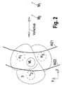
- Fig. 2 represents - again viewed in the Z direction - z.
- B. a crankshaft for a 6-cylinder in-line engine with three in their rotational position to the center bearing ML differently positioned crank pin H1-H3.
- the cheek processing could be done partially with the crankshaft stationary, by working the tool in question WZ1 or WZ2 in the feed direction, ie in the X direction, the end face of the cheek.
- the processing of the cheek surface is preferably carried out with rotating crankshaft.
- FIG. 3 shows the relationships when two separate tools WZ1, WZ2 process two different crank pins H1, H2 simultaneously.
- the tools WZ1 and WZ2 can be moved independently of each other in the X direction and controlled in their speed.
- the connecting factor is the rotation of the crankshaft, which is likewise controlled to rotate about the center bearings, as a workpiece, which can also be stopped in certain work operations.
- crank pin H1 is offset by about 120 ° clockwise relative to the center bearing.
- Fig. 3 also shows the forcibly present relationship between the processing of the two stroke bearings H1 and H2, especially in the optimization of multiple simultaneous processing operations in terms of z. B. to consider a particular chip thickness is:
- journal bearing pin H1 At the processing point of the journal bearing pin H1 should also be achieved as possible the same chip thickness. Also, the center of the pin bearing pin H 1 - assuming the same rotational speed and the same diameter of the tools WZ1 and WZ2 - has been pivoted by the angle ⁇ relative to the center of the stroke bearing until the next cutting edge engages the tool WZ1.
- the offset a 1 caused thereby at the machining point is negligibly greater than a 2 , since the distance from the center of the center bearing ML to the machining point on the stroke bearing H1 is slightly greater than the center of the stroke bearing H 1 .
- This offset a 1 has a pronounced component x 1 in the X direction, which must be compensated by appropriate movement of the tool WZ1 in the X direction.
- a 1 remains as the cutting distance ⁇ I u1 in the Y direction. This would result in the thin chip illustrated on the right in FIG. 3 with a maximum thickness of only h 1max , which is much smaller than the optimum chip thickness.
- the speed of the tool WZ1 In order to get to the optimum chip thickness also at this processing point, the speed of the tool WZ1 must be reduced compared to the speed of WZ2 so that the cutting distance .DELTA.I u1 increases so far until the desired chip thickness is reached on the crankpins H 1 . In this case, a reduction of the speed of tool WZ1 to up to about 30% of the speed of tool WZ2 is necessary.
- the secondary optimization target could be a cutting speed that should be within a predetermined target corridor or should not exceed a certain maximum value.
- predetermined bandwidths of certain cutting parameters it may be that not all processing stations compliance with this bandwidth is possible.
- the predetermined bandwidth range must be increased or a third-rate optimization parameter must be specified.
- This third optimization variable could, for example, be the chip length (especially when processing cheek side surfaces).
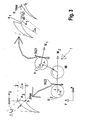
- FIG. 4 shows a crankshaft z. B. for a four-cylinder in-line engine, in which the crank pins H1 and H2 with respect to the center bearing ML are facing in the radial direction.
- crankshaft would continue to rotate about the center of the center bearing ML in the indicated direction (clockwise) while the tool WZ would rotate counterclockwise turns to achieve synchronous milling.
- crankshaft In general, a rotation of the crankshaft can not be completely dispensed with, since otherwise a processing of a bearing journal currently taking place at another location of the crankshaft would no longer bring about processing progress.
- z. B. a bearing pin works as follows:
- the cutter is delivered relatively slowly despite the rotation of the workpiece to the radial nominal dimension. Too fast radial delivery would not only increase the chip thickness inadmissible, but above all - because of the then large chip length due to relatively large looping between a disc-shaped outer cutter, the rotates about an axis parallel to the journal axis, and the current processing point - even the hereby correlating shear forces which are introduced into the workpiece, relatively high.
- the cutter is moved so slowly radially against the center of the journal to be machined that the existing allowance is detected only after an entry angle of about 50-70, preferably about 60 °, of the journal circumference by the cutter , From this point, a complete revolution of the bearing journal to be machined, preferably a little more, ie about 370 °, must be processed in order to achieve an optimum adaptation of the actual contour to the nominal contour of the journal.
- the extension of the milling cutter can then take place directly radially.
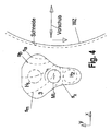
- correction points are arranged in FIG. 5 along the machining path with an intermediate angle of approximately 10-15 ° to the center of the stroke bearing journal to be machined.
- the approximation of the actual circumferential contour to the desired circumferential contour can be measured and by varying each of the correction points-by appropriately inputting correction values for the individual correction points into the machine control-the actual contour obtained be subsequently corrected empirically.
- the peripheral contour of the cheek is further flattened at one point.
- the peripheral contour of the cheek surface is also machined by means of external milling.
- the external milling according to the invention is - by appropriate control of the rotational position, ie the rotational speed of the crankshaft in relation to the X-displacement of the milling cutter - not only any desired (ie outwardly curved) contour achievable, but also level, z. B. lying tangentially to the center bearing ML of the crankshaft flats.
- Such flat cutouts are either for retrofitting z. B. balancing weights needed, or even for balancing the crankshaft directly in the clamping of the machining.
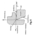
- FIG. 6 shows a section through a cutting tool WZ; FIG.
- a turning tool where most designations and angles apply to both turning and milling.
- the cutting edge for example, the main cutting edge S, ⁇ carried by the tool face A and the primary clearance surface A formed edge ⁇ formed, and the secondary cutting edge S 'by the rake face A ⁇ and ⁇ extending at an angle to the main clearance surface A secondary clearance surface A' ⁇ .
- the sharpened cutting edge S in Fig. 6 is never fully pointed in practice, but must have some roundness, the cutting edge rounding SKV, to prevent the cutting edge from breaking.
- the tool reference plane P r is a plane through the selected cutting point, perpendicular to the assumed cutting direction.
- the tool reference plane P r is possible chosen so that it is parallel or perpendicular to an axis of the tool. A determination must be made individually for each tool type.
- the tool reference plane P r is a plane parallel to the bearing surface of the shank in conventional lathe tools, for milling tools a plane containing the axis of the milling tool.
- the assumed working plane P f is a plane through the selected cutting point, perpendicular to the tool reference plane P r and parallel to the assumed feed direction.
- the tool back plane P p is a plane through the selected cutting point, perpendicular to the tool reference plane P r and perpendicular to the assumed working plane P f .
- P r , P p and P f thus represent a coordinate system by the assumed cutting point.
- the tool cutting plane P s (see FIG. 8) is a plane through the cutting point, tangent to the cutting edge S and perpendicular to the tool reference plane P r . If the tool cutting edge S is at right angles to the feed direction, the tool cutting plane P s and the tool back plane P p coincide.
- the tool orthogonal plane P 0 is a plane through the cutting point, perpendicular to the tool reference plane P r and perpendicular to the tool cutting plane P s .
- tool orthogonal plane P 0 and assumed working plane P f coincide.
- the main cutting edge stands in a tool setting angle ⁇ r between the tool cutting plane P s and the assumed working plane P f measured in the tool reference plane P r .
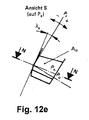
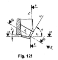
- FIGS. 12a-12f the position of the individual sections and views can be taken directly in part from FIGS. 9 and 10.
- This tool inclination angle ⁇ s is an acute angle whose apex points to the cutting corner. It is positive if the cutting edge to be viewed from the cutting corner lies on the side of the tool reference plane P r facing away from the assumed cutting direction.
- ⁇ is generally called the clearance angle of a cutting edge.
- Fig. 13 shows a cheek plate, which is screwed onto the disc-shaped base body of the milling cutter - preferably on both sides - the end face, and thereby protrudes both radially and frontally over the main body.
- the platelet-shaped cheek plate with its plane, the tool cutting plane P s at a small angle ⁇ to the working plane P f , which is composed of the feed direction (X direction) and lying in the XY plane cutting direction.
- the outermost edge rounded by the corner radius R of approximately 1.6 mm, protrudes obliquely outwards from the base body and forms the axially most projecting point relative to the main body of the milling cutter.
- an additional rotation of the crankshaft may additionally be necessary if, for example, the cheek surface approaches the crankpin H 2 and around it to be edited.
- the length of the cutting plate is the extension of the plate in the radial direction of the cutter body, the width in the tangential direction of the disc-shaped tool body and the thickness the extension in the direction of the cutting tip closest to the axial direction ,
- Fig. 13b shows in the same direction as Fig. 13a, the processing of the lateral surface of a pin of the crankshaft by a pin plate.
- a pin plate In such a plate are meant as length and width in the plan view of Fig. 13b apparent sides, as a tenon plates usually square inserts are used, which can thus be used four times in a row.
- the pin plates can be fastened with their outer, cutting edge at a slight angle deviating from the Z direction within the ZX plane on the main body of the disc cutter, if at the same time also given a deviation from the Z direction within the ZY plane ,
Landscapes
- Engineering & Computer Science (AREA)
- Mechanical Engineering (AREA)
- Milling Processes (AREA)
- Shafts, Cranks, Connecting Bars, And Related Bearings (AREA)
Abstract
Description
Die Erfindung betrifft ein Verfahren zum spanenden Bearbeiten der Stirnflächen als auch Umfangsflächen, die sowohl zentrisch als auch exzentrisch angeordnet sein können, bei Kurbelwellen, siehe die unter Art. 54(3) EPÜ fallende
Gerade Kurbelwellen stellen wegen der zu bearbeitenden, exzentrisch liegenden, z. B. Mantelflächen der Hublagerzapfen oder Stirnflächen der Wangen und der formbedingten Instabilität der Kurbelwelle als Werkstück immer hohe Anforderungen an die Bearbeitungsverfahren.Just crankshafts make because of the machined, eccentric lying, z. B. lateral surfaces of the Hublagerzapfen or faces of the cheeks and the shape-related instability of the crankshaft as a workpiece always high demands on the machining process.
Üblicherweise werden Kurbelwellen durch spanende Bearbeitung mit bestimmten Schneiden, also Drehen, Fräsen, Drehräumen etc., vorbearbeitet, und anschließend die Feinbearbeitung auf ein Maß mittels Schleifen durchgeführt, wobei bisher in der Regel das Härten der Werkstückoberflächen nach der spanenden Vorbearbeitung und vor dem Schleifen erfolgt.Usually, crankshafts are machined by machining with certain cutting edges, ie turning, milling, turning spaces, etc., and then the fine machining is carried out to a degree by means of grinding, hitherto generally the hardening of the workpiece surfaces takes place after the cutting pre-machining and before grinding ,
Obwohl theoretisch spanende Bearbeitungsverfahren zur Verfügung stehen, mit denen die Bearbeitung sowohl der zentrischen Mittellager als auch der exzentrischen Hublager und Stirnseiten der Wangenflächen möglich ist, wird aus Wirtschaftlichkeitsgründen meist eine Bearbeitung mit unterschiedlichen Verfahren vorgenommen:Although theoretically machining processes are available, with which the machining of both the centric center bearing and the eccentric stroke bearing and end faces of the cheek surfaces is possible, for economic reasons usually a processing is carried out with different methods:
So hat sich in der jüngsten Vergangenheit das Dreh-Drehräumen für die Bearbeitung der Mittellager durchgesetzt, wobei am schnell rotierenden, auf der Mittellagerachse eingespannten, Werkstück mit einem zu einer Bogenkontur, meist einer Kreiskontur oder Kreissegmentkontur, gebogenen Räumnadel gearbeitet wird.Thus, in the recent past, the rotary lathe has prevailed for the machining of the center bearing, being worked on the fast rotating, clamped on the center bearing axis, workpiece with a curved contour, usually a circular contour or circular segment contour, curved broach.
Meist werden dabei auch die exzentrischen Stirnflächen der Wangen mitbearbeitet.Usually also the eccentric faces of the cheeks are worked on.
Für die Bearbeitung der exzentrischen Hublagerzapfen, also deren Mantelflächen, hat sich dagegen das Innenfräsen, also das Fräsen mit einem ringförmigen Fräser, der an seinem Innenumfang nach innen gerichtete Schneiden aufweist, etabliert. Däbei dreht sich die Kurbelwelle während der Bearbeitung meist nicht, sondern der Innenfräser rotiert und bewegt sich zusätzlich auf einer Kreisbahn, um den im inneren Freiraum des inneren Fräsers befindlichen Hublagerzapfen herum. Die Schnittgeschwindigkeit wird dabei ausschließlich durch die Bewegung des Innenfräsers erzielt. Einer der Nachteile dabei ist, daß gerade bei der Zapfenbearbeitung wegen der gleichgerichteten Krümmung von Zapfen und Fräser eine große Umschlingung die Folge ist, also oft mehrere Schneiden gleichzeitig im Eingriff sind. Hohe Querkrafteinleitungen in das Werkstück sind die Folge. Wegen der stillstehenden Kurbelwelle ist die gleichzeitige Bearbeitung mehrerer Hublagerzapfen durch jeweils separate Innenfräs-Einheiten möglich, sofern die entsprechenden Hublagerzapfen auch in axialer Richtung weit genug voneinander beabstandet sind, um unterschiedliche Innenfräs-Einheiten daran angreifen zu lassen.For the machining of the eccentric crankpins, ie their lateral surfaces, on the other hand, the internal milling, so milling with an annular cutter, which has on its inner circumference inwardly directed cutting, established. Däbei the crankshaft does not rotate during machining usually, but the inner cutter rotates and moves in addition to a circular path around the located in the inner space of the inner cutter crankpins around. The cutting speed is achieved exclusively by the movement of the internal cutter. One of the disadvantages of this is that just in the journal processing because of the rectified curvature of pin and cutter a large wrap is the result, so often several blades are engaged simultaneously. High shear forces in the workpiece are the result. Because of the stationary crankshaft, the simultaneous processing of multiple crankpins by separate Innenfräs units is possible, provided that the corresponding crankpins are far enough apart in the axial direction to allow different Innenfräs units attack it.
Die beschriebenen Verfahren haben sich in der Großserien-Fertigung von Kurbelwellen, etwa für Pkw-Motoren, durchgesetzt, da sie trotz ausreichender Bearbeitungsgenauigkeit sehr viel niedrigere Bearbeitungszeiten pro Kurbelwelle oder pro Zapfen ermöglichen als z. B. des Drehen.The described methods have prevailed in the large-scale production of crankshafts, such as for passenger car engines, since they allow much lower processing times per crankshaft or per pin despite sufficient machining accuracy than z. B. of turning.
Bei einem solchen nach innen verzahnten Fräser ist zwar die Wartung, Reparatur, Neubestückung und Justierung von Wendeschneidplatten etc. schwieriger, jedoch bietet ein solches Werkzeug den prinzipiellen Vorteil einer guten und stabilen Lagerung in einem Werkzeugsupport, der das ringförmige Werkzeug allseits umschließt. Dies ist notwendig, da der Support das ringförmige Werkzeug beim Innenfräsen aufgrund der stillstehenden Kurbelwelle nicht nur in X-, sondern auch in Y-Richtung definiert verfahren können muß. Die Drehzahl des Innenfräsers bleibt jedoch während eines Umlaufes um den zu bearbeitenden Lagerzapfen in der Regel konstant und ist unabhängig von der derzeitigen Relativlage von Werkstück und Werkzeug zueinander.Although with such an internally toothed cutter maintenance, repair, replacement and adjustment of indexable inserts, etc. is more difficult, but such a tool offers the principal advantage of a good and stable storage in a tool support that surrounds the annular tool on all sides. This is necessary because the support must be able to move the annular tool during internal milling due to the stationary crankshaft not only defined in the X, but also in the Y direction. However, the speed of the internal cutter remains constant during a rotation around the bearing pin to be machined in the rule and is independent of the current relative position of the workpiece and tool to each other.
Eine Verfahrbarkeit des Supportes, welcher den Innenfräser dreht, ausschließlich in X-Richtung, nicht jedoch zusätzlich in Y-Richtung, ist nur dann ausreichend, wenn einerseits das Werkstück während der Bearbeitung definiert drehend angetrieben wird (C-Achse des Werkstückes) und andererseits der freie Innendurchmesser des Innenfräsers größer ist als der Hub der größten zu bearbeitenden Kurbelwelle.A mobility of the support, which rotates the internal cutter, only in the X direction, but not additionally in the Y direction, is only sufficient if, on the one hand, the workpiece during machining defined rotatably driven (C-axis of the workpiece) and the other free inner diameter of the inner cutter is greater than the stroke of the largest crankshaft to be machined.
Gerade bei Maschinen, bei denen mehrere Werkzeugsupporte vorhanden sind, um mit mehreren Werkzeugen, also z. B. Innenfräsern, gleichzeitig am selben Werkstück zu arbeiten, bedeutet es unter dem Strich eine Vereinfachung und Einsparung, wenn bei jedem der mehreren Supporte auf die Realisierung der Y-Achse verzichtet werden kann, obwohl für die dann notwendige Drehung an den Spindelstöcken der in der Regel beiderseits eingespannten und angetriebenen Kurbelwelle zusätzlich die C-Achse vorhanden sein muß.Especially for machines where multiple tool supports are available to work with several tools, ie z. B. internal cutters, at the same time to work on the same workpiece, it means a bottom line simplification and saving, if can be dispensed with the realization of the Y-axis in each of the several supports, although for the then necessary rotation of the headstocks in the Usually both sides clamped and driven crankshaft in addition the C-axis must be present.
In diesem Fall rotiert bei gleichzeitiger Bearbeitung mehrerer Hublagerzapfen die Kurbelwelle mit gleichbleibender Drehzahl, und auch die verschiedenen Innenfräser drehen sich mit gleicher und während einer Zapfenbearbeitung gleichbleibender Drehzahl.In this case, with simultaneous machining of multiple crankpins the crankshaft rotates at a constant speed, and the various internal milling cutters rotate with the same and during a pin machining constant speed.
Ein derartiges Fräswerkzeug ist mit einer Vielzahl von Schneiden, die meist als Wendeschneidplatten auf einem ringförmigen (beim Innenfräser) oder scheibenförmigen (beim Außenfräser) Grundkörper im Innenumfangsbereich bzw. im Außenumfangsbereich angeordnet sind. Die Überholung bzw. Neubestückung oder Nachjustierung solcher Fräser ist zum einen zeitaufwendig, und wegen der nicht unerheblichen Kosten der verwendeten Schneidmittel kostenaufwendig.Such a milling tool comes with a variety of cutting edges, mostly as indexable inserts an annular (in the internal milling cutter) or disk-shaped (in the case of the external milling cutter) basic body in the inner peripheral region or in the outer peripheral region are arranged. The overhaul or re-fitting or readjustment of such cutters is time-consuming and costly because of the not inconsiderable costs of the cutting means used.
In die zu minimierenden Bearbeitungskosten pro Kurbelwelle gehen daher anteilig nicht nur die Investitionskosten für die Maschine ein, deren Anteil pro Kurbelwelle mit sinkender Bearbeitungszeit abnimmt, sondern auch ein durch die Standzeit des Werkzeuges beeinflußter Kostenfaktor, den es zu minimieren gilt.Therefore, not only the investment costs for the machine, whose share per crankshaft decreases with decreasing processing time, but also a cost factor influenced by the service life of the tool, which are to be minimized, are proportionately included in the processing costs per crankshaft to be minimized.
Es ist daher die Aufgabe gemäß der vorliegenden Erfindung, ein spanendes Bearbeitungsverfahren für die Bearbeitung von Kurbelwellen zu schaffen, bei dem durch gleichzeitige Bearbeitung durch mehrere Werkzeugeinheiten eine kurze Bearbeitungszeit pro Kurbelwelle möglich ist, und unter Einhaltung einer ausreichenden Maßhaltigkeit eine optimal lange Standzeit der Werkzeuge ermöglicht wird.It is therefore the object of the present invention to provide a machining process for machining crankshafts, in which a short machining time per crankshaft is possible by simultaneous machining by a plurality of tool units, and allows a perfectly long tool life while maintaining a sufficient dimensional stability becomes.
Diese Aufgabe wird durch die Merkmale des Anspruches 1 gelöst. Vorteilhafte Ausführungsformen ergeben sich aus den Unteransprüchen.This object is solved by the features of
Bei dieser Lösung waren unterschiedliche Negativ-Randbedingungen zu berücksichtigen:In this solution, different negative boundary conditions were considered:
Grundsätzlich ist ein zentrisches Spannen der Kurbelwelle, also ein Spannen auf der Mittellager-Achse gegenüber der wesentlich komplizierteren exzentrischen Spannung auf einer Hublagerachse, wie sie beispielsweise für die Hublagerbearbeitung mittels Dreh-Drehräumen notwendig ist, vorzuziehen.Basically, a centric clamping of the crankshaft, so a clamping on the central bearing axis over the much more complicated eccentric stress on a crank bearing axis, as it is necessary for example for the Hublagerbearbeitung by means of rotary lathe, preferable.
Relativ unproblematisch ist die gleichzeitige Bearbeitung von z. B. zwel Hublagerzapfen, die in ihrer radialen Position gegenüber mit der Mittellager-Achse der Kurbelwelle übereinstimmen, und lediglich axial beabstandet sind. In diesem Fall ist die Bearbeitung mit zwei analog geführten und angetriebenen Werkzeugeinheiten, beispielsweise einem Tandemwerkzeug oder einem Werkzeugsatz, möglich.Relatively unproblematic is the simultaneous processing of z. B. zwel crankpins that match in their radial position with respect to the center bearing axis of the crankshaft, and only axially spaced. In this case, machining is possible with two analogously guided and driven tool units, for example a tandem tool or a tool set.
Nicht alle Kurbelwellen bieten jedoch diese geometrischen Voraussetzungen, weswegen auch die Bearbeitung von radial nicht übereinstimmenden Hublagerzapfen durch separate Werkzeugeinheiten möglich sein soll. Dabei ist die Anwendung von Verfahren, bei denen die Schnittgeschwindigkeit primär durch die Drehung der Kurbelwelle erreicht wird, problematisch, als dann bei der relativ schnellen Rotation der Kurbelwelle die ebenso schnelle Nachführung der Werkzeugeinheiten für die Hublagerbearbeitung in X- und eventuell zusätzlich auch in Y-Richtung problematisch ist. Dieser Aspekt spricht für das Fräsen als Bearbeitungsverfahren. Dabei ist speziell das Außenfräsen wegen des einfacher zu handhabenden Werkzeugs und vor allem wegen der Möglichkeit, auch plane Außenflächen am Werkstück erzeugen zu können, zu bevorzugen.However, not all crankshafts offer these geometrical conditions, which is why the machining of radially inconsistent crankpins by separate tool units should be possible. In this case, the use of methods in which the cutting speed is achieved primarily by the rotation of the crankshaft, problematic, than then with the relatively fast rotation of the crankshaft, the equally fast tracking of the tool units for the Hublagerbearbeitung in X- and possibly also in Y- Direction is problematic. This aspect speaks for milling as a machining process. It is especially the external milling because of the easier-to-use tool and especially because of the ability to produce flat outer surfaces on the workpiece to prefer.
Um bei gleichzeitigem Einsatz mehrerer Werkzeuge am Werkstück eine weitere Reduzierung der Bearbeitungszeit zu erreichen, können die Werkzeugstandzeit erhöht und/oder die Zerspanungsleistung pro Zeiteinheit erhöht werden.In order to achieve a further reduction of the machining time with the simultaneous use of several tools on the workpiece, the tool life can be increased and / or the cutting power per unit time can be increased.
Die Zerspanungsleistung pro Zeiteinheit läßt sich mit gesteigerter Schnittgeschwindigkeit erhöhen, die jedoch regelmäßig die Lebensdauer des Werkzeuges (Gesamt-Zerspanungsvolumen pro Werkzeug) sinken läßt.The cutting performance per unit of time can be increased with increased cutting speed, which, however, regularly the life of the tool (total metal removal per tool) can decrease.
Eine Erhöhung der Spandicke, die ebenfalls die Zerspanungsleistung pro Zeiteinheit anhebt, ist nicht möglich, da im Gegenteil die Reduzierung der Spandicke im Hinblick auf die Minimierung der Schnittkräfte, die auf das Werkstück einwirken, und damit Verbesserung der Maßhaltigkeit, erwünscht ist.Increasing the chip thickness, which also raises the chip removal rate per unit time, is not possible because, conversely, the reduction in chip thickness is desirable in terms of minimizing the cutting forces acting on the workpiece and thereby improving dimensional stability.
Eine Erhöhung der Schnittgeschwindigkeit ist bei dem bekannten Verfahren des Highspeed-Fräsens (HS-Fräsen) auf 350-500 m/min und teilweise sogar darüber möglich, was durch positive Schneidengeometrie, bestimmte Materialien der Schneidplatten (sowohl Grundmaterial als auch Beschichtung) möglich wurde.An increase in the cutting speed is possible in the known method of high-speed milling (HS milling) to 350-500 m / min and sometimes even above, which was possible by positive cutting geometry, certain materials of the inserts (both base material and coating).
Gerade beim HS-Fräsen mit 180-800, insbesondere mit 350-500 m/min haben Untersuchungen jedoch ergeben, daß zwar wie bisher bekannt das Gesamtzerspanungsvolumen eines Werkzeuges grundsätzlich mit steigender Schnittgeschwindigkeit abnimmt, dabei jedoch bei Spandicken von 0,05-0,4 mm, insbesondere bei 0,1-0,2 mm, bei unterschiedlichen Schneidstoffen und Schneidstoffbeschichtungen eine optimal hohe Lebensleistung, also Zerspanungsvolumen während der Lebensdauer, des Werkzeuges erzielt wird.Exactly when HS milling with 180-800, in particular with 350-500 m / min, however, investigations have shown that although, as previously known, the Gesamtzerspanungsvolumen a tool basically decreases with increasing cutting speed, but at chip thicknesses of 0.05-0.4 mm, in particular at 0.1-0.2 mm, with different cutting materials and cutting material coatings an optimal high life performance, ie cutting volume during the life of the tool is achieved.
Weitere Untersuchungen haben ergeben, daß die Einhaltung dieses Wertes bzw. Wertebereiches z. B. beim Fräsen, bei dem der Span eine in seinem Verlauf sich ändernde Dicke besitzt, durch Einhaltung für die mittlere Spandicke, also den arithmetischen Mittelwert oder den integrierten Mittelwert der Dicke des Spanes oder die maximale Dicke des Spanes, ausreicht. Unter Einhaltung dieses Parameters wird dann versucht, die Schnittgeschwindigkeit möglichst hoch zu halten, um die Bearbeitungszeiten zu reduzieren.Further investigations have shown that compliance with this value or range z. B. in milling, in which the chip has a varying thickness in its course, by adhering to the average chip thickness, so the arithmetic mean or the integrated average of the thickness of the chip or the maximum thickness of Spanes sufficient. Following this parameter, an attempt is then made to keep the cutting speed as high as possible in order to reduce the processing times.
Bei der ermittelten optimalen Spandicke hat es sich weiterhin als sinnvoll erwiesen, soweit als möglich im Gleichlauf zu fräsen. Dies hängt vermutlich damit zusammen, daß bei einer mittleren Spandicke von z. B. 0,1-0,2 mm im Gleichlauf und vor allem bei der für das HS-Fräsen eingesetzten positiven Schneidengeometrie die auf das Werkstück wirkenden Schnittkräfte trotz des unterbrochenen Schnittes beim Fräsen nur relativ geringe dynamische Belastungen in das Werkstück einbringen und wegen des Einhakens der positiv geformten Schneide auch ein Ausweichen des Werkstückes zur Seite, welches in Maßungenauigkeiten resultiert, weitestgehend vermieden wird.In the determined optimal chip thickness, it has also proven to be useful to mill as far as possible in synchronism. This is probably related to the fact that at a mean chip thickness of z. B. 0.1-0.2 mm in synchronism and especially in the used for HS milling positive cutting geometry bring the cutting forces acting on the workpiece despite the interrupted cut during milling only relatively small dynamic loads in the workpiece and because of the hooking The positive-shaped cutting edge and a deflection of the workpiece to the side, which results in dimensional inaccuracies, is largely avoided.
Wenn zwei voneinander unabhängig arbeitende und ansteuerbare Fräseinheiten an ein und derselben dreh- und antreibbaren Kurbelwelle unterschiedliche exzentrische Bearbeitungsflächen bearbeiten, und ein optimaler Wert bzw. Bereich für die Spandicke eingehalten werden soll, kann unter Umständen nur an einer Bearbeitungsstelle die gewünschte maximale Schnittgeschwindigkeit, z. B. die Schnittgeschwindigkeit des HS-Fräsens, erzielt werden.If two independently operating and controllable milling units on the same rotatable and drivable crankshaft edit different eccentric machining surfaces, and an optimum value or range for the chip thickness is to be met, may only at one processing point, the desired maximum cutting speed, z. As the cutting speed of HS milling, can be achieved.
Um an den anderen Bearbeitungsstellen die Spandicke bzw., mittlere Spandicke im optimalen Bereich zu halten, muß unter Umständen dort die Drehzahl des Fräsers reduziert werden, und damit einhergehend auch die Schnittgeschwindigkeit. Aus diesem Grund wird beim Beginn der Zapfenbearbeitung der Fräser nicht direkt radial bis auf Sollmaß gefahren, sondern - während sich die Kurbelwelle dreht, langsam, während einer Drehung des zu bearbeitenden Zapfens von 30 - 90, vorzugsweise von 50 - 70°, langsam bis auf das radiale Sollmaß gefahren. Dadurch wird auch beim Beginn der Bearbeitung eines Lagerzapfens die Vorgabe hinsichtlich der Spandicke eingehalten, und es werden zu Beginn der Bearbeitung keine unzulässig hohen Querkräfte in das Werkstück eingebracht. Nach Erreichen des radialen Sollmaßes muß ein vollständiger Umlauf der Zapfenfläche, vorzugsweise ca. 100° Umfangsfläche, abgearbeitet werden, um zu einem optimalen Bearbeitungsergebnis zu gelangen.In order to keep the chip thickness or, average chip thickness in the optimum range at the other processing points, under certain circumstances there must be reduced the speed of the milling cutter, and consequently also the cutting speed. For this reason, the cutter is not driven directly radially to specified size at the beginning of the pin machining, but slowly - while the crankshaft rotates, slowly, during a rotation of the pin to be machined from 30 - 90, preferably from 50 - 70 °, slowly up to moved the radial nominal dimension. As a result, the specification regarding the thickness of the chip is maintained even at the beginning of the machining of a bearing journal, and no excessively high transverse forces are introduced into the workpiece at the beginning of the machining. After reaching the radial nominal dimension, a complete revolution of the pin surface, preferably about 100 ° circumferential surface, must be processed in order to arrive at an optimal processing result.
Wenn es keinen optimalen Wert für die Spandicke im Hinblick auf die Lebensleistung eines Werkzeuges gibt, würde die Optimierung der unabhängigen Werkzeugeinheiten im Hinblick auf maximale Schnittgeschwindigkeit erfolgen. Diese vor allem für die Graugußbearbeitung (GGG60-GGG80) ermittelten Gesetzmäßigkeiten können für andere Werkstückmaterialien wie Stahl, bei denen auch andere Gruppen von Schneidstoffen eingesetzt werden, unter Umständen auch gültig sein.If there is no optimal chip thickness value for a tool's life performance, the optimization of the independent tooling units would be in terms of maximum cutting speed. These laws, which are mainly used for gray cast iron machining (GGG60-GGG80), may also apply to other workpiece materials, such as steel, where other groups of cutting materials are used.
Durch zusätzliche Verwendung einer positiven Schneidengeometrie anstelle der bisher beim Fräsen angewandten negativen Schneidengeometrie, die vor allem in Verbindung mit den niedrigen mittleren oder maximalen Spandicken dennoch zu einer ausreichenden Standzeit der Schneidmittel führt, ergibt sich wiederum eine-Reduzierung der Schnittkräfte und in der Folge auch eine Reduzierung der notwendigen Antriebsleistungen für das Werkzeug, die bei den angegebenen Größenverhältnissen nur etwa die Hälfte bis ein Drittel der für das Innenfräsen oder Dreh-Drehräumen benötigten Leistung liegt. Auch dadurch werden - neben den niedrigeren Energiekosten - die Abwärmeprobleme der Antriebe, die sich immer negativ auf die gesamte Maschine und das Bearbeitungsergebnis auswirken, minimiert.The additional use of a positive cutting geometry instead of the negative cutting geometry previously used in milling, which still leads to a sufficient service life of the cutting means, especially in conjunction with the low average or maximum thicknesses, in turn results in a reduction of the cutting forces and consequently also a Reduction of the necessary drive power for the tool, which is only about one-half to one-third of the power required for internal milling or turning and turning with the given proportions. This also minimizes - in addition to the lower energy costs - the waste heat problems of the drives, which always have a negative effect on the entire machine and the machining result.
Das Hochgeschwindigkeitsfräsen kann dabei insbesondere nicht nur am ungehärteten, sondern auch am gehärteten (z. B. 60 bis 62 Rockwell -Härtegrade HRC, insbesondere durchgehärtet) Werkstück durchgeführt werden. In diesem Fall wird als Schneidstoff vorzugsweise Mischkeramik oder polykristallines Bornitrid (PKB), bei letzterem insbesondere wieder kubisches Bornitrid (CBN) eingesetzt. Vorzugsweise wird daher zunächst eine Hartmetall-Schneidplatte wie üblich gesintert, die jedoch Vertiefungen im Schneidenbereich, z. B. in der Spanfläche und zur Schneidkante hin offen, aufweist. In diese Vertiefungen des Grundkörpers wird CBN-Pulver gefüllt und anschließend gesintert.The high-speed milling can be carried out in particular not only on the uncured but also on the hardened (eg 60 to 62 Rockwell hardness grades HRC, in particular through-hardened) workpiece. In this case, preferably mixed ceramic or polycrystalline boron nitride (PKB) is used as the cutting material, in particular cubic boron nitride (CBN) in the latter case. Preferably, therefore, a carbide cutting plate is sintered as usual, but the wells in the cutting area, z. B. in the rake face and the cutting edge open, has. In these recesses of the body CBN powder is filled and then sintered.
Nicht nur die Ecken von Wendeschneidplatten können auf diese Art und Weise verstärkt werden, sondern durch Anordnung mehrerer CBN-Pallets nebeneinander entlang einer Schneidenkante oder eines balkenförmigen CBN-Einsatzes kann eine ganze Schneidkante verstärkt werden. Auch ungehärteter Stahl oder Guß kann damit bearbeitet werden, auch mittels Fräsen.Not only the corners of indexable inserts can be reinforced in this way, but by arranging several CBN pallets side by side along a cutting edge or a bar-shaped CBN insert, an entire cutting edge can be reinforced. Even unhardened steel or castings can be machined, also by means of milling.
Diese Schneidstoffe können auch ohne Kühlschmiermittel, also trocken, eingesetzt werden, was Entsorgungskosten und Umweltprobleme erspart.These cutting materials can also be used without cooling lubricant, ie dry, which saves disposal costs and environmental problems.
Dadurch ist es möglich, den bei konventioneller Herstellung (spanende Bearbeitung vor dem Härten) auftretenden Verzug des Werkstückes, bedingt durch den Härteprozeß, bereits durch die spanende Bearbeitung mit abzuarbeiten. Da beim Hochgeschwindigkeitsfräsen und insbesondere beim Hochgeschwindigkeitsfräsen am gehärteten Werkstück Obefächenqualitäten erzielbar sind, die als Endzustand des Werkstückes akzeptabel sind, ist dadurch der völlige Wegfall zumindest des Grobschleifbearbeitungsvorganges möglich.This makes it possible to process the distortion of the workpiece which occurs during conventional production (machining before hardening), due to the hardening process, already by the machining. Since in high-speed milling and especially in high-speed milling Obefächenqualitäten can be achieved, which are acceptable as the final state of the workpiece, thereby the complete omission of at least the rough grinding machining process is possible.
Als besonders günstig hat es sich erwiesen, bei der Bearbeitung der Zapfen- und Wangenflächen bei Kurbelwellen, die aus Guß oder Stahl bestehen, und im ungehärteten Zustand spanend bearbeitend werden mittels eines Außenrundfräsers, insbesondere mittels eines scheibenförmigen Fräsers mit Schneiden am Umfangsbereich, folgende Parameter einzuhalten:
- Schnittgeschwindigkeit bei der Schruppbearbeitung: mindestens 180, besser 250-600 m/min,
- Schnittgeschwindigkeit bei der Schlichtbearbeitung: mindestens 200, besser 300-800 m/min,
- Spandicke: 0,05 - 0,5 mm insbesondere 0,1-0,3 mm.
- Cutting speed during roughing: at least 180, better 250-600 m / min,
- Cutting speed during finishing: at least 200, better 300-800 m / min,
- Chip thickness: 0.05-0.5 mm, in particular 0.1-0.3 mm.
Als Werkzeug wird dabei in der Regel ein scheibenförmiger, drehend angetriebener Werkzeuggrundkörper mit aufgesetzten Wendeschneidplatten verwendet. Dabei sind die Schneidplatten hinsichtlich ihres Einsatzzweckes (Bearbeitung der Stirnflächen an den Wangen, Bearbeitung der Mantelflächen an den Zapfen der Hauptlagerstelle und Hublagerstellen, Erstellen der Unterstiche am Übergang zwischen Mantelflächen und Stirnflächen) unterschiedlich gestaltet und auch in bezug zum Werkzeugträger bzw. zum Werkstück unterschiedlich positioniert:
bis 200 (komplett)
bis 200 (komplett)
up to 200 (complete)
up to 200 (complete)
Die Angabe des Grundmaterials bezieht sich auf die bekannten ISO-Anwendungsgruppen. Dabei besteht
- K10:
aus 94,2 % Wolframkarbid (WC), 5,5 % Kobalt (Co) und 0,3 % ... (Ta/C) - K20:
aus 93,2 % WC, 6 % Co und 0,6% Ta/C und 0,2 % Titankarbid (TiC)
- K10: 94.2% tungsten carbide (WC), 5.5% cobalt (Co) and 0.3% ... (Ta / C)
- K20: 93.2% WC, 6% Co and 0.6% Ta / C and 0.2% titanium carbide (TiC)
Die Biegefestigkeit beträgt 1.900 N/m2 bei K10 und 2.000 N/m2 bei K20.The flexural strength is 1,900 N / m 2 at K10 and 2,000 N / m 2 at K20.
Bei den angegebenen Beschichtungen sind die einzelnen Verbindungen schichtweise nacheinander in der angegebenen Reihenfolge von innen nach außen aufgetragen.In the case of the coatings given, the individual compounds are applied one after the other layer by layer in the order given from the inside to the outside.
Eine Ausführungsform gemäß der Erfindung ist im folgenden anhand der Figuren beispielhaft näher beschrieben. Es zeigen:
- Fig. 1:
- eine Prinzipdarstellung des Gleichlauf-Außenfräsens an einem Kurbelwellenzapfen,
- Fig. 2:
- eine Prinzipdarstellung bei gleichzeitiger Bearbeitung an zwei verschiedenen Hublagerzapfen,
- Fig. 3:
- Detaildarstellungen von zwei unterschiedlichen Bearbeitungsstellen,
- Fig. 4:
- eine Bahnkurve bei Zapfenbearbeitung,
- Fig. 5:
- eine Darstellung der Bahnkurve beim Zapfenfräsen,
- Fig. 6:
- den Schneidkeil des Werkzeuges in Prinzipdarstellung,
- Fig. 7 und 8:
- definierte Ebenen im Werkzeugbezugssystem,
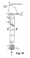
- Fig. 9 und 10:
- die Lagewinkel der Schneide im Werkzeugbezugssystem am Beispiel eines Drehmeißels für das Längsdrehen (Fig. 9) und das Plandrehen (Fig. 10).
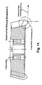
- Fig. 11:
- einen Schnitt durch einen Fräsmesserkopf,
- Figuren 12a-12f:
- Schnitte durch das Werkzeug des Fräsmesserkopfes gemäß Fig. 11,
- Fig. 13a:
- zeigt den Einsatz einer Wangenplatte, betrachtet in Y-Richtung,
- Fig. 13b:
- den Einsatz einer Zapfenplatte in Blickrichtung Y,
- Fig. 1:
- a schematic representation of the synchronous external milling on a crankshaft journal,
- Fig. 2:
- a schematic diagram with simultaneous processing on two different crankpins,
- 3:
- Detailed representations of two different processing points,
- 4:
- a trajectory in tenoning,
- Fig. 5:
- a representation of the trajectory during trench milling,
- Fig. 6:
- the cutting wedge of the tool in schematic representation,
- FIGS. 7 and 8:
- defined levels in the tool reference system,
- FIGS. 9 and 10:
- the position angle of the cutting edge in the tool reference system using the example of a turning tool for longitudinal turning (FIG. 9) and face turning (FIG. 10).
- Fig. 11:
- a section through a Fräsmesserkopf,
- FIGS. 12a-12f:
- Cuts through the tool of the Fräsmesserkopfes of FIG. 11,
- Fig. 13a:
- shows the use of a cheek plate, viewed in the Y direction,
- Fig. 13b:
- the use of a pin plate in the direction Y,
Fig. 1 zeigt in Blickrichtung der Z-Achse die grundsätzliche Situation der Bearbeitung einer Umfangsfläche, beispielsweise des Zapfens einer Kurbelwelle, aber auch einer unrunden Umfangsfläche, mittels Außenfräsen. Eine Vergrößerung der Bearbeitungsstelle ist im rechten Teil der Fig. 1 dargestellt.Fig. 1 shows in the direction of the Z-axis, the basic situation of processing a peripheral surface, for example, the pin of a crankshaft, but also a non-circular peripheral surface by means of external milling. An enlargement of the processing point is shown in the right part of Fig. 1.
Das Werkstück soll von dem größeren Rohmaß auf das kleinere Endmaß bearbeitet werden.The workpiece should be machined from the larger raw dimension to the smaller final dimension.
Dabei stehen die Schneiden S, von denen nur eine eingezeichnet ist, über den Werkzeuggrundkörper radial vor, um diesen Abtrag bewirken zu können. Der Werkzeuggrundkörper ist dabei in X-Richtung definiert verfahrbar und rotiert gegen den Uhrzeigersinn. Da das Fräsen im Gleichlauf geschehen soll, rotiert das Werkstück im Uhrzeigersinn, so daß sich an der Bearbeitungsstelle Werkzeug und Werkstück in die gleiche Richtung bewegen.In this case, the cutting edges S, of which only one is shown, project radially beyond the tool body in order to be able to effect this removal. The tool body is defined in the X direction movable and rotates counterclockwise. Since the milling is to be done in synchronism, the workpiece rotates clockwise, so move at the processing point tool and workpiece in the same direction.
Wie die vergrößerte Darstellung zeigt, wird die neue Schneide S einen Span 1 erzeugen, der durch zwei konvexe und eine konkave Bogensegmente im Querschnitt begrenzt wird, und die Form eines flachen, unregelmäßigen Dreiecks, besitzt.As the enlarged illustration shows, the new cutting edge S will produce a
Dabei ist die konkave Seite die durch den vorhergehenden Schnitt erzeugte Flanke, und die lange konvexe Seite, die durch den die neue Schneide S erzeugte Flanke. Die kurze konvexe Flanke ist die entlang des Umfanges des Zweigstückes gemessene Länge ΔIu, also die Umfangslänge zwischen dem Auftreffen von zwei hintereinander angeordneten Schneiden des Werkzeuges auf dem Umfang des Werkstückes.Here, the concave side is the flank created by the previous cut, and the long convex side is the flank created by the new cutting edge S. The short convex flank is the length ΔI u measured along the circumference of the branch piece, that is to say the circumferential length between the impact of two successively arranged cutting edges of the tool on the circumference of the workpiece.
In der Praxis behält der Span 1 natürlich nicht die aus Fig. 1 ersichtliche Form bei, sondern wird aufgrund der Ablenkung an der Spanfläche der Schneide spiralig aufgerollt.In practice, the
Aus Fig. 1 ist zu erkennen, daß der Span 2 - in Durchlaufrichtung der Schneide betrachtet - zunächst in seiner Spandicke, z. B. h1, schnell zunimmt bis zur maximalen Spandicke hmax. Von dort aus nimmt die Spandicke relativ langsam bis zum Ende kontinuierlich (z. B. hx) ab.From Fig. 1 it can be seen that the span 2 - viewed in the direction of passage of the cutting edge - first in his Chip thickness, z. B. h 1 , increases rapidly up to the maximum chip thickness h max . From there, the chip thickness decreases relatively slowly to the end continuously (eg h x ).
Aus dieser Darstellung ist ersichtlich - wenn die Differenz zwischen Rohmaß und Endmaß gleich bleibt und die Drehgeschwindigkeit des Werkstückes ebenfalls gleich bleibt - daß eine Verringerung der Drehgeschwindigkeit des Werkzeuges eine Vergrößerung des Schnittabstandes ΔIu bewirkt, und damit auch eine Vergrößerung von hmax.From this representation can be seen - if the difference between raw and final dimensions remains the same and the rotational speed of the workpiece also remains the same - that a reduction in the rotational speed of the tool causes an increase in the cutting distance .DELTA.I u , and thus an increase of h max .
Fig. 2 stellt - wiederum in Z-Richtung betrachtet - z. B. eine Kurbelwelle für einen 6-Zylinder-Reihenmotor mit drei in ihrer Drehlage zum Mittellager ML unterschiedlich positionierten Hubzapfen H1-H3 dar.Fig. 2 represents - again viewed in the Z direction - z. B. a crankshaft for a 6-cylinder in-line engine with three in their rotational position to the center bearing ML differently positioned crank pin H1-H3.
An dieser Kurbelwelle sind - an unterschiedlichen axialen Positionen - zwei separate scheibenförmige Außenfräser (WZ1, WZ2) im Einsatz. Eins der Werkzeuge könnte beispielsweise den Hubzapfen H1, das andere den Hubzapfen H2 bearbeiten, wie in Fig. 2 dargestellt, aber ebenso könnte eines der Werkzeuge einen Hubzapfen, das andere der Werkzeuge die Stirnfläche einer Wange bearbeiten.At this crankshaft - at different axial positions - two separate disc-shaped external cutters (WZ1, WZ2) in use. One of the tools could for example handle the crankpin H1, the other the crankpin H2, as shown in Fig. 2, but also one of the tools could handle a crank pin, the other of the tools the end face of a cheek.
In letzterem Fall könnte theoretisch die Wangenbearbeitung teilweise bei stillstehender Kurbelwelle erfolgen, indem sich das betreffende Werkzeug WZ1 oder WZ2 in Vorschubrichtung, also in X-Richtung, die Stirnfläche der Wange entlangarbeitet. Da bei Stillstand der Kurbelwelle jedoch an der an anderer axialer Position stattfindenden Bearbeitung einer Mantelfläche, sei es eines Hubzapfens H oder eines Mittellagers ML, kein Bearbeitungsfortschritt erzielbar ist, wird auch die Bearbeitung der Wangenfläche vorzugsweise bei drehender Kurbelwelle erfolgen.In the latter case, theoretically, the cheek processing could be done partially with the crankshaft stationary, by working the tool in question WZ1 or WZ2 in the feed direction, ie in the X direction, the end face of the cheek. However, since at standstill of the crankshaft at the taking place at another axial position processing a lateral surface, be it a crank pin H or a center bearing ML, no processing progress can be achieved, the processing of the cheek surface is preferably carried out with rotating crankshaft.
Dabei ergeben sich - bei einem Beginn der Wangenbearbeitung in der in Fig. 4 dargestellten Position der Kurbelwelle und anschließendem Weiterdrehen der Kurbelwelle - Schneidbahnen sa, sb, sm, sx, von denen einige in Fig. 4 eingezeichnet sind.This results in - at a start of the cheek processing in the position of the crankshaft shown in Fig. 4 and subsequent further rotation of the crankshaft - cutting paths s a , s b , s m , s x , some of which are shown in Fig. 4.
Wie ersichtlich, haben diese Schneidbahnen - wegen des Gleichlaufes des Fräsers - mit der Werkstückdrehung - an ihrem Beginn einen größeren Abstand voneinander als an ihrem Ende, also dem Punkt des Auslaufens der Schneide aus der Wangenseitenfläche.As can be seen, these cutting paths - because of the synchronism of the milling cutter - with the workpiece rotation - at their beginning a greater distance from each other than at its end, so the point of leakage of the cutting edge of the cheek side.
Fig. 3 zeigt die Zusammenhänge auf, wenn zwei separate Werkzeuge WZ1, WZ2 zwei verschiedene Hubzapfen H1, H2 gleichzeitig bearbeiten. Die Werkzeuge WZ1 und WZ2 können unabhängig voneinander in X-Richtung definiert verfahren und in ihrer Drehzahl gesteuert werden. Die verbindende Größe ist jedoch die Drehung der um die Mittellager ebenfalls gesteuert drehbar angetriebenen Kurbelwelle als Werkstück, welche bei bestimmten Arbeitsoperationen auch angehalten werden kann.FIG. 3 shows the relationships when two separate tools WZ1, WZ2 process two different crank pins H1, H2 simultaneously. The tools WZ1 and WZ2 can be moved independently of each other in the X direction and controlled in their speed. The connecting factor, however, is the rotation of the crankshaft, which is likewise controlled to rotate about the center bearings, as a workpiece, which can also be stopped in certain work operations.
In der in Fig. 3 dargestellten Situation befindet sich Hubzapfen H2 auf einer Linie mit dem Mittellager ML1 und dem Mittelpunkt M1 und M2 der Werkzeuge WZ1 oder WZ2. Der Hubzapfen H1 ist gegenüber dem Mittellager um ca. 120° in Uhrzeigerrichtung versetzt.In the situation shown in Fig. 3 is Hubzapfen H2 in line with the center bearing ML1 and the center M 1 and M 2 of the tools WZ1 or WZ2. The crank pin H1 is offset by about 120 ° clockwise relative to the center bearing.
Wenn - wie angegeben - die Werkzeuge WZ1 und WZ2 jeweils im GegenUhrzeigersinn rotieren, und die Kurbelwelle - wie an deren Mittellager ML eingezeichnet - im Uhrzeigersinn, wird ersichtlich an dem Hublager H1 im Gleichlaufverfahren gefräst, was aus den oben angegebenen Gründen gewünscht wird.When, as indicated, the tools WZ1 and WZ2 each rotate counterclockwise, and the crankshaft - as shown at its center bearing ML - clockwise, it can be seen milled on the roller bearing H1 in synchronism, which is desired for the reasons given above.
Am Hublager H2 könnte der Eindruck entstehen, daß es sich hier um ein Gegenlauffräsen handelt, da sich das Werkzeug WZ2 an dieser Stelle nach unten bewegt, der Hubzapfen H2 jedoch nach oben.At the stroke bearing H2, the impression could arise that this is a counter-rotation milling, since the tool WZ2 moves downwards at this point, but the lifting pin H2 moves upwards.
Auf die Absolutbewegung des Hubzapfens kommt es jedoch bei der Beurteilung, ob Gleichlauf- oder Gegenlauffräsen vorliegt, nicht an, sondern darauf, ob das Hublager H2 relativ um seinen Mittelpunkt eine Drehung vollzieht, die seine Oberfläche an der Bearbeitungsstelle immer in der gleichen Richtung bewegen läßt wie den Fräser.On the absolute movement of the crank pin, however, it does not matter in the assessment of whether constant velocity or countercurrent milling is present, but on whether the stroke bearing H2 rotates relatively around its center, which always moves its surface in the same direction at the processing point like the router.
Der in Fig. 3 - absolut betrachtet - nach oben wandernde Hubzapfen H2 rollt jedoch ersichtlich entlang des Werkzeuges WZ2 nach oben ab, so daß also relativ zum Mittelpunkt des Hublagers H2 eine Drehung des Hublagers im Uhrzeigersinn stattfindet und damit an der Bearbeitungsstelle de facto Gleichlauf herrscht.However, in Fig. 3 - in absolute terms - upwardly migrating Hubzapfen H2 rolls but obviously along the tool WZ2 from above, so that takes place relative to the center of the lifting bearing H2 rotation of the stroke bearing in a clockwise direction and thus at the processing point de facto synchronization prevails ,
Fig. 3 zeigt ferner den zwangsweise vorhandenen Zusammenhang zwischen der Bearbeitung an den beiden Hublagern H1 und H2, die vor allem bei der Optimierung von mehreren gleichzeitig ablaufenden Bearbeitungsvorgängen im Hinblick z. B. auf eine bestimmte Spandicke zu berücksichtigen ist:Fig. 3 also shows the forcibly present relationship between the processing of the two stroke bearings H1 and H2, especially in the optimization of multiple simultaneous processing operations in terms of z. B. to consider a particular chip thickness is:
Es sei angenommen, daß sich der Fräser WZ2 in Relation zur Kurbelwelle 1 - von welcher in Fig. 3 nur das Mittellager ML und die zwei momentan bearbeiteten Hubzapfen H1 und H2 der Übersichtlichkeit halber dargestellt sind - so schnell relativ zueinander drehen, daß zwischen dem Eingriff zweier aufeinanderfolgender Schneiden des Werkzeuges WZ2 am Hublager H2 die Kurbelwelle um den Winkel Δα weitergedreht wurde. Da in Fig. 3 der Mittelpunkt des Hublagers H2 und der Mittelpunkt der Kurbelwelle, also des Mittellagers ML, auf einer Linie mit der Mitte M2 des Werkzeuges WZ2 liegen, bewirkt der Schwenkwinkel Δα einen Versatz a2 des Auftreffpunktes der neuen Schneide gegenüber der alten Schneide, der fast genau in Y-Richtung verläuft.It is assumed that the cutter WZ2 in relation to the crankshaft 1 - of which in Fig. 3, only the center bearing ML and the two currently machined crank pins H1 and H2 are shown for clarity - rotate so fast relative to each other that between the engagement two successive cutting of the tool WZ2 at the stroke bearing H2, the crankshaft was further rotated by the angle Δα. Since in Fig. 3, the center of the stroke bearing H2 and the center of the crankshaft, so the center bearing ML lie on a line with the center M2 of the tool WZ2, the pivot angle Δα causes an offset a 2 of the impact point of the new blade relative to the old blade which runs almost exactly in the Y direction.
Dadurch muß nur eine sehr geringe X-Komponente x2 durch entsprechende X-Bewegung des Werkzeuges WZ2 erfolgen, und der sich ergebende Schnittabstand ΔIu2 bedingt einen Spanquerschnitt, dessen Dicke der optimalen Spandicke entsprechen soll.As a result, only a very small X component x 2 must take place by means of a corresponding X movement of the
An der Bearbeitungsstelle des Hublagerzapfens H1 soll ebenfalls möglichst die gleiche Spandicke erzielt werden. Auch der Mittelpunkt des Hublagerzapfens H1 ist - gleiche Drehzahl und gleichen Durchmesser der Werkzeuge WZ1 und WZ2 vorausgesetzt - um den Winkelbetrag Δα gegenüber der Mitte des Hublagers verschwenkt worden, bis vom Werkzeug WZ1 die nächste Schneide in Eingriff gelangt.At the processing point of the journal bearing pin H1 should also be achieved as possible the same chip thickness. Also, the center of the pin bearing pin H 1 - assuming the same rotational speed and the same diameter of the tools WZ1 and WZ2 - has been pivoted by the angle Δα relative to the center of the stroke bearing until the next cutting edge engages the tool WZ1.
Der an der Bearbeitungsstelle dadurch bewirkte Versatz a1 ist dabei vernachlässigbar größer als a2, da der Abstand von der Mitte des Mittellagers ML zur Bearbeitungsstelle am Hublager H1 geringfügig größer ist als zur Mitte des Hublagers H1. Dieser Versatz a1 besitzt eine ausgeprägte Komponente x1 in X-Richtung, die durch entsprechende Bewegung des Werkzeuges WZ1 in X-Richtung ausgeglichen werden muß. Damit bleibt von a1 nur ein relativ geringer Anteil als Schnittabstand ΔIu1 in Y-Richtung übrig. Dies würde den in Fig. 3 rechts außen dargestellten dünnen Span mit einer Maximaldicke von nur h1max ergeben,- welche sehr viel geringer ist als die optimale Spandicke.The offset a 1 caused thereby at the machining point is negligibly greater than a 2 , since the distance from the center of the center bearing ML to the machining point on the stroke bearing H1 is slightly greater than the center of the stroke bearing H 1 . This offset a 1 has a pronounced component x 1 in the X direction, which must be compensated by appropriate movement of the tool WZ1 in the X direction. Thus, only a relatively small proportion of a 1 remains as the cutting distance ΔI u1 in the Y direction. This would result in the thin chip illustrated on the right in FIG. 3 with a maximum thickness of only h 1max , which is much smaller than the optimum chip thickness.
Um auch an dieser Bearbeitungsstelle auf die optimale Spandicke zu kommen, muß die Drehzahl des Werkzeuges WZ1 gegenüber der Drehzahl von WZ2 so reduziert werden, daß der Schnittabstand ΔIu1 soweit ansteigt, bis die gewünschte Spandicke auch am Hublagerzapfen H1 erreicht wird. Dabei ist eine Reduzierung der Drehzahl von Werkzeug WZ1 auf bis zu etwa 30 % der Drehzahl von Werkzeug WZ2 notwendig.In order to get to the optimum chip thickness also at this processing point, the speed of the tool WZ1 must be reduced compared to the speed of WZ2 so that the cutting distance .DELTA.I u1 increases so far until the desired chip thickness is reached on the crankpins H 1 . In this case, a reduction of the speed of tool WZ1 to up to about 30% of the speed of tool WZ2 is necessary.
Neben dem beschriebenen ersten Optimierungsziel einer bestimmten - mittleren oder maximalen - Spandicke könnte das sekundäre Optimierungsziel eine Schnittgeschwindigkeit sein, die sich innerhalb eines vorgegebenen Zielkorridors bewegen soll oder einen bestimmten Maximalwert nicht überschreiten soll.In addition to the described first optimization target of a particular average or maximum chip thickness, the secondary optimization target could be a cutting speed that should be within a predetermined target corridor or should not exceed a certain maximum value.
Im ersteren Fall würde dies in dem in Fig. 3 dargestellten Bearbeitungsfall dazu führen, daß bei der Bearbeitung des Hublagers H2 die Drehzahlen des Werkstückes und des Werkzeuges WZ2 in Relation zueinander - so daß am Hublager H2 die gewünschte Spandicke erhalten bleibt, so erhöht werden, daß sich die Drehzahl von Werkzeug WZ2 am oberen Ende der vorgegebenen Bandbreite für die Schnittgeschwindigkeit bewegt. Dadurch ergibt sich auch eine Erhöhung der Drehzahl des Werkzeuges WZ1, wodurch die Schnittgeschwindigkeit am Hublagerzapfen H1 ebenfalls noch innerhalb der vorgegebenen Bandbreite für die Schnittgeschwindigkeit liegen sollte.In the former case, this would result in the processing shown in Fig. 3 to the fact that in the processing of the stroke bearing H2, the speeds of the workpiece and the tool WZ2 in relation to each other - so that the desired chip thickness is maintained at the stroke bearing H2, are increased, that the speed of tool WZ2 moves at the upper end of the predetermined bandwidth for the cutting speed. This also results in an increase in the rotational speed of the tool WZ1, whereby the cutting speed on the crank journal H 1 should also be within the specified bandwidth for the cutting speed.
Bei Vorgabe einer Obergrenze für die Schnittgeschwindigkeit dagegen würde diese Obergrenze auf die Bearbeitung am Hublagerzapfen H2 angewandt werden, welche die höhere Schnittgeschwindigkeit gegenüber der Bearbeitung am Hublagerzapfen H1 besitzt, so daß dadurch eine absolute Obergrenze der Schnittgeschwindigkeit automatisch an beiden vorhandenen Bearbeitungsstellen eingehalten wird.When setting an upper limit for the cutting speed, however, this upper limit would be applied to the machining on the crankpin H 2 , which has the higher cutting speed compared to the machining on the journal bearing pin H 1 , so that an absolute upper limit of the cutting speed is automatically maintained at both existing processing points.
Bei der gleichzeitigen Bearbeitung von mehr als zwei Stellen an einer Kurbelwelle ist analog das begrenzende Kriterium bei absoluten Höchst- oder Mindestwerten immer auf die Bearbeitungsstelle mit dem relativ höchsten bzw. niedrigsten entsprechenden Wert anzuwenden.When simultaneously machining more than two locations on a crankshaft, the limiting criterion for absolute maximum or minimum values must always be applied to the processing location with the relatively highest or lowest corresponding value.
Bei der Anwendung von vorgegebenen Bandbreiten bestimmter Schnittparameter kann es sein, daß nicht für alle Bearbeitungsstellen die Einhaltung dieser Bandbreite möglich ist. In diesem Fall ist dann entweder der vorgegebene Bandbreitenbereich zu vergrößern oder es muß ein drittrangiger Optimierungsparameter vorgegeben werden. Diese dritte Optimierungsgröße könnte beispielsweise die Spanlänge (vor allem bei Bearbeitung von Wangenseitenflächen) sein.When using predetermined bandwidths of certain cutting parameters, it may be that not all processing stations compliance with this bandwidth is possible. In this case, either the predetermined bandwidth range must be increased or a third-rate optimization parameter must be specified. This third optimization variable could, for example, be the chip length (especially when processing cheek side surfaces).
Die in Fig. 3 dargestellten gegenseitigen Abhängigkeiten bei Einhaltung einer bestimmten Spandicke treten verstärkt dann auf, wenn eine von mehreren gleichzeitigen Bearbeitungsstellen an der Kurbelwelle die Bearbeitung einer Stirnfläche einer Wange ist, wie in Fig. 4 dargestellt. Die Darstellung in Fig. 4 zeigt eine Kurbelwelle z. B. für einen Vierzylinder-Reihenmotor, bei der sich in radialer Richtung die Hubzapfen H1 und H2 bezüglich des Mittellagers ML gegenüberstehen.The mutual dependencies shown in FIG. 3, while maintaining a specific chip thickness, are increasingly pronounced when one of a plurality of simultaneous machining points on the crankshaft is the machining of an end face of a cheek, as shown in FIG. 4. The illustration in Fig. 4 shows a crankshaft z. B. for a four-cylinder in-line engine, in which the crank pins H1 and H2 with respect to the center bearing ML are facing in the radial direction.
Wenn in der in Fig. 4 dargestellten Position mit der Bearbeitung der Wangenfläche 3 durch das Werkzeug WZ begonnen würde, würde sich die Kurbelwelle um die Mitte des Mittellagers ML weiter in der angegeben Richtung (im Uhrzeigersinn) drehen, während das Werkzeug WZ gegen den Uhrzeigersinn dreht, um Gleichlauffräsen zu erzielen.If machining of the
Auf der Wangenfläche 3 sind einige der sich dadurch ergebenden Schneidbahnen sa, sb, sm, sx eingezeichnet.On the
Wegen der gleichzeitigen Drehung der Kurbelwelle ergeben sich dadurch Spanquerschnitte, die wiederum am Beginn des Spanes deutlich größer sind als gegen Ende des Spanes, und zusätzlich unterscheiden sich die Späne stark in der Spanlänge, abhängig von der jeweiligen Lage der Schneidbahn auf der Wangenfläche 3.Because of the simultaneous rotation of the crankshaft resulting in chip cross-sections, which in turn are significantly greater at the beginning of the chip than towards the end of the chip, and additionally the chips differ greatly in the chip length, depending on the respective position of the cutting path on the cheek surface. 3
Auf eine Drehung der Kurbelwelle kann in der Regel nicht vollständig verzichtet werden, da sonst ein an anderer Stelle der Kurbelwelle gerade stattfindende Bearbeitung eines Lagerzapfens keinen Bearbeitungsfortschritt mehr zeitigen würde.In general, a rotation of the crankshaft can not be completely dispensed with, since otherwise a processing of a bearing journal currently taking place at another location of the crankshaft would no longer bring about processing progress.
Wenn somit an einer Kurbelwelle gleichzeitig mehrere Wangenseitenflächen oder eine Wangenseitenfläche gleichzeitig mit der Bearbeitung eines Lagerzapfens stattfindet, treten die am Beispiel der Fig. 3 dargestellten Diskrepanzen der Spandicken zwischen den verschiedenen Bearbeitungsstellen bei gleichen Drehzahlen und Durchmessern aller Werkzeuge verstärkt auf, so daß verstärkt die Drehzahlen, und/oder bei Wangenbearbeitung auch die Bewegung in Querrichtung, also X-Richtung durch den Fräser, ständig verändert werden müssen, um in jeder Phase der Bearbeitung und an allen Bearbeitungsstellen gleichzeitig die gewünschte optimale Spandicke einzuhalten.Thus, if several cheek side surfaces or a cheek side surface takes place simultaneously with the processing of a journal on a crankshaft, the discrepancies shown in the example of FIG. 3 spandex between the different processing points at the same speeds and diameters of all tools reinforced, so that amplifies the speeds , And / or cheek processing and the movement in the transverse direction, ie X-direction through the cutter must be constantly changed in order to comply with the desired optimal chip thickness in each phase of processing and at all processing points simultaneously.
Wie Fig. 5 zeigt, wird auch bei Beginn der Bearbeitung der Mantelfläche z. B. eines Lagerzapfens werkstückschonend wie folgt vorgegangen:As shown in FIG. 5, z. B. a bearing pin works as follows:
Der Fräser wird trotz der Drehung des Werkstückes relativ langsam bis auf das radiale Sollmaß zugestellt. Eine zu schnelle radiale Zustellung würde nicht nur die Spandicke unzulässig erhöhen, sondern vor allem - wegen der dann großen Spanlänge aufgrund relativ großer Umschlingung zwischen einem scheibenförmigen Außenfräser, der um eine Achse parallel zur Lagerzapfenachse rotiert, und der momentanen Bearbeitungsstelle - auch die hiermit korrelierenden Querkräfte, welche in das Werkstück eingeleitet werden, relativ hoch werden.The cutter is delivered relatively slowly despite the rotation of the workpiece to the radial nominal dimension. Too fast radial delivery would not only increase the chip thickness inadmissible, but above all - because of the then large chip length due to relatively large looping between a disc-shaped outer cutter, the rotates about an axis parallel to the journal axis, and the current processing point - even the hereby correlating shear forces which are introduced into the workpiece, relatively high.
Wie Fig. 5 zeigt, wird der Fräser so langsam radial gegen den Mittelpunkt des zu bearbeitenden Lagerzapfens vorwärtsbewegt, daß das vorhandene Aufmaß erst nach einem Einfahrwinkel von ca. 50 - 70, vorzugsweise etwa 60°, des Lagerzapfen-Umfanges durch den Fräser erfaßt ist. Von diesem Punkt ab muß eine vollständige Umdrehung des zu bearbeitenden Lagerzapfens, vorzugsweise etwas mehr, also ca. 370°, abgearbeitet werden, um eine optimale Anpassung der Ist-Kontur an die Soll-Kontur des Zapfens zu erreichen. Das Ausfahren des Fräsers kann dann direkt radial erfolgen.As shown in FIG. 5, the cutter is moved so slowly radially against the center of the journal to be machined that the existing allowance is detected only after an entry angle of about 50-70, preferably about 60 °, of the journal circumference by the cutter , From this point, a complete revolution of the bearing journal to be machined, preferably a little more, ie about 370 °, must be processed in order to achieve an optimum adaptation of the actual contour to the nominal contour of the journal. The extension of the milling cutter can then take place directly radially.
Zusätzlich sind in Fig. 5 entlang der Bearbeitungsbahn Korrekturpunkte mit einem Zwischenwinkel von etwa 10 - 15° zum Mittelpunkt des zu bearbeitenden Hublagerzapfens angeordnet.In addition, correction points are arranged in FIG. 5 along the machining path with an intermediate angle of approximately 10-15 ° to the center of the stroke bearing journal to be machined.
Nach dem Herstellen der ersten Stücke einer zu bearbeitenden Serie kann die Annäherung der Ist-Umfangskontur an die Soll-Umfangskontur gemessen werden und durch Abänderung jedes einzelnen der Korrekturpunkte - durch entsprechende Eingabe von Korrekturwerten für die einzelnen Korrekturpunkte in die Maschinensteuerung - die erzielte Ist-Kontur nachträglich empirisch korrigiert werden.After making the first pieces of a series to be machined, the approximation of the actual circumferential contour to the desired circumferential contour can be measured and by varying each of the correction points-by appropriately inputting correction values for the individual correction points into the machine control-the actual contour obtained be subsequently corrected empirically.
In Fig. 4 ist ferner die Umfangskontur der Wange an einer Stelle eben abgeflacht. Teilweise wird auch die Umfangskontur der Wangenfläche mittels Außenfräsen bearbeitet. Mit dem Außenfräsen gemäß der Erfindung ist - durch entsprechende Steuerung der Drehlage, also der Drehgeschwindigkeit der Kurbelwelle in Relation zur X-Verschiebung des Fräsers - nicht nur jede gewünschte (also nach außen gekrümmte) Kontur erzielbar, sondern auch ebene, z. B. tangential zum Mittellager ML der Kurbelwelle liegende Abflachungen. Derartige ebene Anfräsungen werden entweder zum nachträglichen Befestigen z. B. von Ausgleichsgewichten benötigt, oder auch zum Wuchten der Kurbelwelle direkt in der Aufspannung der spanenden Bearbeitung.In Fig. 4, the peripheral contour of the cheek is further flattened at one point. In part, the peripheral contour of the cheek surface is also machined by means of external milling. With the external milling according to the invention is - by appropriate control of the rotational position, ie the rotational speed of the crankshaft in relation to the X-displacement of the milling cutter - not only any desired (ie outwardly curved) contour achievable, but also level, z. B. lying tangentially to the center bearing ML of the crankshaft flats. Such flat cutouts are either for retrofitting z. B. balancing weights needed, or even for balancing the crankshaft directly in the clamping of the machining.
Selbst konkave, also vertiefte, Umfangskonturen, können hergestellt werden, solange deren Krümmungsradius größer ist als der Radius des scheibenförmigen Außenfräsers.Even concave, ie recessed, peripheral contours, can be produced as long as their radius of curvature is greater than the radius of the disc-shaped outer cutter.
Dabei zeigt Fig. 6 einen Schnitt durch ein spanendes Werkzeug WZ; beispielsweise einen Drehmeißel, wobei die meisten Bezeichnungen und Winkel sowohl für das Drehen, als auch für das Fräsen gelten. Dabei wird die Schneide, beispielsweise die Hauptschneide S, durch die durch die Spanfläche Aγ sowie die Hauptfreifläche Aα gebildete Kante gebildet, und die Nebenschneide S' durch die Spanfläche Aγ und die im Winkel zur Hauptfreifläche Aα verlaufende Nebenfreifläche A'α. Die in Fig. 6 spitz gezeichnete Schneide S ist in der Praxis niemals vollständig spitz, sondern muß eine gewisse Rundung, die Schneidkantenverrundung SKV, besitzen, um ein Ausbrechen der Schneidkante zu verhindern.FIG. 6 shows a section through a cutting tool WZ; FIG. For example, a turning tool, where most designations and angles apply to both turning and milling. Here, the cutting edge, for example, the main cutting edge S, γ carried by the tool face A and the primary clearance surface A formed edge α formed, and the secondary cutting edge S 'by the rake face A γ and α extending at an angle to the main clearance surface A secondary clearance surface A' α. The sharpened cutting edge S in Fig. 6 is never fully pointed in practice, but must have some roundness, the cutting edge rounding SKV, to prevent the cutting edge from breaking.
In den Fig. 7 und 8 sind verschiedene Richtungen und Ebenen bezüglich des Werkzeuges definiert.In Figs. 7 and 8 different directions and planes are defined with respect to the tool.
Dabei ist die Werkzeug-Bezugsebene Pr eine Ebene durch den ausgewählten Schneidenpunkt, und zwar senkrecht zur angenommenen Schnittrichtung. Die Werkzeug-Bezugsebene Pr ist dabei möglichst so gewählt, daß sie parallel oder senkrecht zu einer Achse des Werkzeuges liegt. Eine Festlegung muß für jeden Werkzeugtyp individuell erfolgen. Bei Drehmeißeln ist die Werkzeug-Bezugsebene Pr eine Ebene parallel zur Auflagefläche des Schaftes bei konventionellen Drehmeißeln, bei Fräswerkzeugen eine Ebene, die die Achse des Fräswerkzeuges enthält.In this case, the tool reference plane P r is a plane through the selected cutting point, perpendicular to the assumed cutting direction. The tool reference plane P r is possible chosen so that it is parallel or perpendicular to an axis of the tool. A determination must be made individually for each tool type. For turning tools, the tool reference plane P r is a plane parallel to the bearing surface of the shank in conventional lathe tools, for milling tools a plane containing the axis of the milling tool.
Die angenommene Arbeitsebene Pf ist eine Ebene durch den ausgewählten Schneidenpunkt, senkrecht stehend auf der Werkzeug-Bezugsebene Pr und parallel zur angenommenen Vorschubrichtung.The assumed working plane P f is a plane through the selected cutting point, perpendicular to the tool reference plane P r and parallel to the assumed feed direction.
Die Werkzeug-Rückebene Pp ist eine Ebene durch den ausgewählten Schneidenpunkt, senkrecht zur Werkzeug-Bezugsebene Pr und senkrecht zur angenommenen Arbeitsebene Pf. Pr, Pp und Pf stellen somit ein Koordinatensystem durch den angenommenen Schneidenpunkt dar.The tool back plane P p is a plane through the selected cutting point, perpendicular to the tool reference plane P r and perpendicular to the assumed working plane P f . P r , P p and P f thus represent a coordinate system by the assumed cutting point.
Die Werkzeug-Schneidenebene Ps (siehe Fig. 8) ist eine Ebene durch den Schneidenpunkt, tangential zur Schneide S und senkrecht zur Werkzeugs-Bezugsebene Pr. Wenn die Werkzeugschneide S rechtwinklig zur Vorschubrichtung liegt, fallen Werkzeug-Schneidenebene Ps und Werkzeug-Rückebene Pp zusammen.The tool cutting plane P s (see FIG. 8) is a plane through the cutting point, tangent to the cutting edge S and perpendicular to the tool reference plane P r . If the tool cutting edge S is at right angles to the feed direction, the tool cutting plane P s and the tool back plane P p coincide.
Die Werkzeug-Orthogonalebene P0 ist eine Ebene durch den Schneidenpunkt, senkrecht zur Werkzeug-Bezugsebene Pr und senkrecht zur Werkzeug-Schneidenebene Ps. Wenn somit die Werkzeugschneide S rechtwinklig zur Vorschubrichtung liegt, fallen Werkzeug-Orthogonalebene P0 und angenommene Arbeitsebene Pf zusammen.The tool orthogonal plane P 0 is a plane through the cutting point, perpendicular to the tool reference plane P r and perpendicular to the tool cutting plane P s . Thus, when the tool cutting edge S is perpendicular to the feed direction, tool orthogonal plane P 0 and assumed working plane P f coincide.
Aus den Figuren 9 und 10 ist - getrennt für das Längsdrehen und das Plandrehen - die Orientierung der einzelnen Werkzeugschneiden zum Werkstück besser ersichtlich. In dieser Aufsicht betrachtet hat das Werkzeug an seiner Schneidenspitze einen Werkzeug-Eckenwinkel εr zwischen der Werkzeug-Schneidenebene Ps der Hauptschneide und der Werkzeug-Schneidenebene P's der Nebenschneide, gemessen in der Werkzeug-Bezugsebene Pr.From Figures 9 and 10 is - separately for the longitudinal turning and facing - the orientation of the individual tool cutting to the workpiece better visible. Viewed in this top view, the tool has at its cutting tip a tool corner angle ε r between the tool cutting plane P s of the main cutting edge and the tool cutting plane P ' s of the minor cutting edge measured in the tool reference plane P r .
Dabei steht die Hauptschneide in einem Werkzeug-Einstellwinkel κr zwischen der Werkzeug-Schneidenebene Ps und der angenommenen Arbeitsebene Pf gemessen in der Werkzeug-Bezugsebene Pr.The main cutting edge stands in a tool setting angle κ r between the tool cutting plane P s and the assumed working plane P f measured in the tool reference plane P r .
In den Figuren 12a - 12f ist die Lage der einzelnen Schnitte und Ansichten zum Teil aus den Figuren 9 und 10 direkt entnehmbar.In FIGS. 12a-12f, the position of the individual sections and views can be taken directly in part from FIGS. 9 and 10.
Die relevanten Winkel dabei sind:
- Werkzeug-Seitenspanwinkel γf: Winkel zwischen der Spanfläche Aγ und der Werkzeug-Bezugsfläche Pr, gemessen in der Arbeitsebene Pf;
- Werkzeug-Rückspanwinkel γp: Winkel zwischen der Spanfläche Aγ und der Werkzeug-Bezugsebene Pr, gemessen in der Werkzeug-Rückebene Pp;
- Werkzeug-Normalspanwinkel γn: Winkel zwischen der Spanfläche Aγ und der Werkzeug-Bezugsebene Pr, gemessen in der Werkzeug-Schneidennormalebene Pn; Der Wert dieses Winkels γn (positiv oder negativ) wird verallgemeinert meist als "positive/negative Schneidengeometrie" bezeichnet.
- Werkzeug-Neigungswinkel λs (Fig. 12e): Winkel zwischen der Schneide S und der Werkzeug-Bezugsebene Pr, gemessen in der Werkzeug-Schneidenebene Ps.
- Tool side rake angle γ f : Angle between the rake face A γ and the tool reference face P r , measured in the working plane P f ;
- Tool back rake angle γ p : angle between the rake face A γ and the tool reference plane P r measured in the tool back plane P p ;
- Tool normal chip angle γ n : angle between the rake face A γ and the tool reference plane P r , measured in the tool cutting normal plane P n ; The value of this angle γ n (positive or negative) is generalized usually referred to as "positive / negative cutting geometry".
- Tool inclination angle λ s (Figure 12e): Angle between the cutting edge S and the tool reference plane P r measured in the tool cutting plane P s .
Dieser Werkzeug-Neigungswinkel λs ist ein spitzer Winkel, dessen Spitze zur Schneidenecke hinweist. Er ist positiv, wenn die von der Schneidenecke aus zu betrachtende Schneide auf der der angenommenen Schnittrichtung abgekehrten Seite der Werkzeug-Bezugsebene Pr liegt.This tool inclination angle λ s is an acute angle whose apex points to the cutting corner. It is positive if the cutting edge to be viewed from the cutting corner lies on the side of the tool reference plane P r facing away from the assumed cutting direction.
Mit α wird generell der Freiwinkel einer Schneide bezeichnet.With α is generally called the clearance angle of a cutting edge.
Fig. 13 zeigt eine Wangenplatte, die auf den scheibenförmigen Grundkörper des Fräsers - vorzugsweise beiderseits - stirnseitig aufgeschraubt ist, und dabei sowohl radial als auch stirnseitig über den Grundkörper übersteht. Um von der Stirnfläche der Wange das Material abzutragen, wird bei rotierendem Fräser dieser in X-Richtung, also radial zum Werkstück, als Vorschubrichtung vorwärts bewegt. Dabei steht die plättchenförmige Wangenplatte mit ihrer Ebene, der Werkzeug-Schneidenebene Ps im kleinen Winkel κ zur Arbeitsebene Pf, die sich aus der Vorschubrichtung (X-Richtung) und der in der X-Y-Ebene liegenden Schnittrichtung zusammensetzt. Dadurch ragt die äußerste, mit dem Eckenradius R von etwa 1,6 mm gerundete Kante des Schneidplättchens vom Grundkörper schräg nach außen und bildet den axial am weitesten vorstehenden Punkt gegenüber dem Grundkörper des Fräsers.Fig. 13 shows a cheek plate, which is screwed onto the disc-shaped base body of the milling cutter - preferably on both sides - the end face, and thereby protrudes both radially and frontally over the main body. In order to remove the material from the end face of the cheek, in the case of a rotating cutter, it is moved forward in the X direction, ie radially to the workpiece, as the feed direction. In this case, the platelet-shaped cheek plate with its plane, the tool cutting plane P s at a small angle κ to the working plane P f , which is composed of the feed direction (X direction) and lying in the XY plane cutting direction. As a result, the outermost edge, rounded by the corner radius R of approximately 1.6 mm, protrudes obliquely outwards from the base body and forms the axially most projecting point relative to the main body of the milling cutter.
Je größer der Winkel κ ist, um so wellenförmiger wird die bearbeitete Stirnfläche der Wange, wie an dem bereits bearbeiteten Teil in Fig. 13 zu erkennen.The larger the angle κ is, the more wavy becomes the machined end face of the cheek, as seen on the already machined part in FIG.
Um die gesamte Stirnfläche einer Wange bearbeiten zu können, ist neben dem in Fig. 13a dargestellten Vorschub in X-Richtung des Fräsers zusätzlich ggf. eine zusätzliche Drehung der Kurbelwelle notwendig, wenn beispielsweise die Wangenfläche bis an den Hublagerzapfen H2 heran und um diesen herum bearbeitet werden soll.In order to be able to machine the entire end face of a cheek, in addition to the advance in the X direction of the milling cutter shown in FIG. 13a, an additional rotation of the crankshaft may additionally be necessary if, for example, the cheek surface approaches the crankpin H 2 and around it to be edited.
Bei einer Wangenplatte wie in Fig. 13a dargestellt, wird als Länge der Schneidplatte die Ausdehnung der Platte in radialer Richtung des Fräsergrundkörpers, als Breite die Ausdehnung in tangentialer Richtung des scheibenförmigen Werkzeuggrundkörpers und als Dicke die Ausdehnung in der der axialen Richtung nächstkommenden Richtung des Schneidplättchens bezeichnet.In the case of a cheek plate as shown in Fig. 13a, the length of the cutting plate is the extension of the plate in the radial direction of the cutter body, the width in the tangential direction of the disc-shaped tool body and the thickness the extension in the direction of the cutting tip closest to the axial direction ,
Fig. 13b zeigt in gleicher Blickrichtung wie Fig. 13a die Bearbeitung der Mantelfläche eines Zapfens der Kurbelwelle durch eine Zapfenplatte. Bei einer derartigen Platte sind als Länge und Breite die in der Aufsicht der Fig. 13b ersichtlichen Seiten gemeint, wobei als Zapfenplatten in der Regel quadratische Wendeschneidplatten verwendet werden, die somit vierfach hintereinander eingesetzt werden können.Fig. 13b shows in the same direction as Fig. 13a, the processing of the lateral surface of a pin of the crankshaft by a pin plate. In such a plate are meant as length and width in the plan view of Fig. 13b apparent sides, as a tenon plates usually square inserts are used, which can thus be used four times in a row.
Die Zapfenplatten können dabei mit ihrer außen liegenden, schneidenden Kante in einem geringen Winkel abweichend von der Z-Richtung innerhalb der Z-X-Ebene am Grundkörper des Scheibenfräsers befestigt sein, wenn gleichzeitig auch eine Abweichung von der Z-Richtung innerhalb der Z-Y-Ebene gegeben ist.The pin plates can be fastened with their outer, cutting edge at a slight angle deviating from the Z direction within the ZX plane on the main body of the disc cutter, if at the same time also given a deviation from the Z direction within the ZY plane ,
Claims (15)
- Method for machining eccentric and centric end faces and exactly such circumferential or peripheral surfaces on a definedly rotatable (C-axis) workpiece (WST) which is a crank shaft clamped on the centric axis (Z1-axis), whereina) the machining is effected by means of external milling,b) the workpiece (WST) is simultaneously machined at a plurality of crank pin bearings as machining surfaces, which do not correspond in their rotational position with respect to the centric axis (Z1), andc) each machining surface is machined by a separate external milling cutter (WZ1, WZ2,...) which is each movable only in one motion path transversely to the workpiece (WST),d) the rotation of the workpiece (WST) is adjusted with respect to the rotational position, the rotational speed (nWST) and the rotational direction in consideration of the present transverse movements and rotational speeds of all different milling cutters (WZ1, WZ2,...) ande) the transverse movement and the rotational speed (n1, n2,...) of each of the milling cutters (WZ1, WZ2) is controlled separately and independently of the other milling cutters (WZ1, WZ2) on the basis of the movement of the workpiece (WST).
- Method according to claim 1,
characterized in that
the motion path of the milling cutters (WZ1, WZ2) is a linear motion path in the X-direction. - Method according to claim 1,
characterized in that
the motion path of the milling cutters (WZ1, WZ2) transversely to the workpiece is an arc-shaped pivotal movement about a Z-axis. - Method according to any one of the preceding claims,
characterized in that
the transverse movement and the rotational speed (n1, n2) of the milling cutters (WZ1, WZ2) is controlled on the basis of the desired movement of the workpiece. - Method according to claim 1 to 3,
characterized in that
the transverse movement and the rotational speed (n1, n2) of the milling cutters (WZ1, WZ2) is controlled on the basis of the actual movement of the workpiece. - Method according to any one of the preceding claims,
characterized in that
the rotation of the workpiece as well as the transverse movement and the rotation of each milling cutter (WZ1, WZ2) is calculated previously for each phase of the milling operation and that the machining is performed according to the machining program resulting therefrom. - Method according to any one of the preceding claims,
characterized in that
the optimization of the movement parameters of the workpiece and the simultaneously operating milling cutters occurs with respect to keeping a maximum average depth of cut (hmitt). - Method according to claim 1 to 6,
characterized in that
the optimization of the movement parameters of the workpiece and the simultaneously operating milling cutters occurs with respect to keeping a maximum depth of cut (hmax). - Method according to claim 1 to 6,
characterized in that
the optimization of the movement parameters of the workpiece and the simultaneously operating milling cutters occurs with respect to a maximization of the cutting speeds (vs1 and vs2, respectively). - Method according to any one of the preceding claims,
characterized in that
the optimization of the movement parameters of the workpiece and the simultaneously operating milling cutters occurs with respect to keeping a particular value range for the average or maximum depth of cut (hmitt), in particular keeping an exact average depth of cut (hmitt 0), in particular at all simultaneously operating milling cutters (WZ1, WZ2). - Method according to any one of the preceding claims,
characterized in that
the optimization of the movement parameters of the workpiece and the simultaneously operating milling cutters occurs with respect to keeping a particular value range for the average depth of cut (hmitt), in particular keeping an exact average depth of cut (hmitt 0), in particular at all simultaneously operating milling units (U1, U2) as primary optimization target and the achieving of a highest possible cutting speed at each of the milling cutters (WZ1, WZ2) being the secondary optimization target. - Method according to any one of the preceding claims,
characterized in that
the milling concerned is a high-speed milling with cutting speeds of 180-800, in particular 350-500 m/min. - Method according to any one of the preceding claims,
characterized in that
the milling cutter has a positive cutting edge geometry. - Method according to any one of the preceding claims,
characterized in that
the milling concerned is the milling performed on a previously hardened workpiece. - Method according to any one of the preceding claims,
characterized in that
during the milling of a bearing pin the milling cutter is fed in the transverse direction of desired measure in the course of a run-in phase of 20° - 100°, in particular of 40° - 60° relative rotation of the bearing pin to be machined.
Applications Claiming Priority (3)
| Application Number | Priority Date | Filing Date | Title |
|---|---|---|---|
| DE19626609 | 1996-07-02 | ||
| DE19626609A DE19626609C2 (en) | 1996-07-02 | 1996-07-02 | Multiple milling on crankshafts |
| PCT/EP1997/003417 WO1998000260A1 (en) | 1996-07-02 | 1997-07-01 | Multiple milling of crankshafts |
Publications (3)
| Publication Number | Publication Date |
|---|---|
| EP0912282A1 EP0912282A1 (en) | 1999-05-06 |
| EP0912282B1 EP0912282B1 (en) | 2002-01-30 |
| EP0912282B2 true EP0912282B2 (en) | 2007-10-24 |
Family
ID=7798706
Family Applications (1)
| Application Number | Title | Priority Date | Filing Date |
|---|---|---|---|
| EP97930457A Expired - Lifetime EP0912282B2 (en) | 1996-07-02 | 1997-07-01 | Multiple milling of crankshafts |
Country Status (9)
| Country | Link |
|---|---|
| US (1) | US6283687B1 (en) |
| EP (1) | EP0912282B2 (en) |
| JP (1) | JP2000503603A (en) |
| AT (1) | ATE212576T1 (en) |
| AU (1) | AU3440297A (en) |
| DE (2) | DE19626609C2 (en) |
| ES (1) | ES2171961T5 (en) |
| WO (1) | WO1998000260A1 (en) |
| ZA (1) | ZA975840B (en) |
Families Citing this family (6)
| Publication number | Priority date | Publication date | Assignee | Title |
|---|---|---|---|---|
| DE19722454A1 (en) * | 1997-05-28 | 1998-12-10 | Boehringer Werkzeugmaschinen | Process for controlling the machining of a workpiece |
| DE19749939C2 (en) * | 1997-11-11 | 2003-10-23 | Boehringer Werkzeugmaschinen | Process for machining workpieces |
| DE10116807B4 (en) * | 2001-04-04 | 2007-01-11 | Erwin Junker Maschinenfabrik Gmbh | Method and device for producing transmission disks of a continuously variable transmission |
| DE102004057111A1 (en) | 2004-11-26 | 2006-06-01 | Niles-Simmons Industrieanlagen Gmbh | Method for intermediate machining of waves |
| DE102011113758B4 (en) * | 2011-09-18 | 2020-12-31 | Mag Ias Gmbh | Method and device for finishing workpieces |
| JP5947113B2 (en) * | 2012-06-01 | 2016-07-06 | Dmg森精機株式会社 | Workpiece processing method using machine tool |
Family Cites Families (14)
| Publication number | Priority date | Publication date | Assignee | Title |
|---|---|---|---|---|
| US1100842A (en) * | 1911-12-16 | 1914-06-23 | Christen Overgaard | Manufacture of crank-shafts and the like. |
| US2215007A (en) * | 1938-12-17 | 1940-09-17 | Ingersoll Milling Machine Co | Metal turning |
| US2942526A (en) * | 1955-03-28 | 1960-06-28 | Elektroantrieb Kurt Maecker Fa | Automatic electric control arrangement for a crankshaft milling machine |
| DE2822346C2 (en) * | 1978-05-22 | 1985-09-05 | GFM Gesellschaft für Fertigungstechnik und Maschinenbau GmbH, Steyr | Electric numerical program control for crankshaft milling machines and crankshaft grinding machines |
| AT358361B (en) * | 1979-03-08 | 1980-09-10 | Gfm Fertigungstechnik | METHOD FOR PROCESSING MULTIPLE CRANKED CRANKSHAFT |
| DE2915662C3 (en) * | 1979-04-18 | 1984-08-09 | Gebr. Heller Maschinenfabrik GmbH, 7440 Nürtingen | Crankshaft milling machine |
| JPS60261634A (en) * | 1984-06-11 | 1985-12-24 | Kioritz Corp | Threading method of crank shaft or the like |
| JPS63102817A (en) * | 1986-10-20 | 1988-05-07 | Honda Motor Co Ltd | Method of machining crankshaft pin |
| DE4316697C2 (en) * | 1993-05-13 | 1995-05-24 | Niles Simmons Industrieanlagen | Wheelset machining method and wheelset machining device |
| DE4446475C2 (en) * | 1994-12-23 | 2000-06-21 | Boehringer Werkzeugmaschinen | Method and machine for machining workpieces |
| DE59605652D1 (en) * | 1995-06-06 | 2000-08-31 | Widia Gmbh | METHOD FOR MACHINING CYLINDRICAL CONTOURS, DEVICE FOR CARRYING OUT THE METHOD AND CUTTING INSERT THEREFOR |
| GB2303091A (en) * | 1995-07-10 | 1997-02-12 | Western Atlas Uk Ltd | Control of circularly asymmetric machining |
| DE19546197C1 (en) * | 1995-12-11 | 1997-01-23 | Widia Gmbh | Rotary milling of workpieces, partic. crankshafts or similar |
| JP3685879B2 (en) * | 1996-07-26 | 2005-08-24 | 東芝機械株式会社 | Machine tool with pivotable spindle head |
-
1996
- 1996-07-02 DE DE19626609A patent/DE19626609C2/en not_active Expired - Lifetime
-
1997
- 1997-07-01 JP JP10503842A patent/JP2000503603A/en active Pending
- 1997-07-01 WO PCT/EP1997/003417 patent/WO1998000260A1/en active IP Right Grant
- 1997-07-01 AU AU34402/97A patent/AU3440297A/en not_active Abandoned
- 1997-07-01 AT AT97930457T patent/ATE212576T1/en not_active IP Right Cessation
- 1997-07-01 EP EP97930457A patent/EP0912282B2/en not_active Expired - Lifetime
- 1997-07-01 US US09/202,865 patent/US6283687B1/en not_active Expired - Lifetime
- 1997-07-01 ZA ZA9705840A patent/ZA975840B/en unknown
- 1997-07-01 DE DE59706250T patent/DE59706250D1/en not_active Expired - Lifetime
- 1997-07-01 ES ES97930457T patent/ES2171961T5/en not_active Expired - Lifetime
Also Published As
| Publication number | Publication date |
|---|---|
| AU3440297A (en) | 1998-01-21 |
| ES2171961T5 (en) | 2008-04-16 |
| ZA975840B (en) | 1998-01-30 |
| ES2171961T3 (en) | 2002-09-16 |
| EP0912282A1 (en) | 1999-05-06 |
| DE19626609A1 (en) | 1998-01-15 |
| EP0912282B1 (en) | 2002-01-30 |
| WO1998000260A1 (en) | 1998-01-08 |
| US6283687B1 (en) | 2001-09-04 |
| JP2000503603A (en) | 2000-03-28 |
| ATE212576T1 (en) | 2002-02-15 |
| DE19626609C2 (en) | 2000-03-09 |
| DE59706250D1 (en) | 2002-03-14 |
Similar Documents
| Publication | Publication Date | Title |
|---|---|---|
| EP0912284B2 (en) | Milling machine | |
| EP0830228B1 (en) | Metal-cutting process for machining cylindrical contours, device for carrying out the process and cutting insert therefor | |
| EP1824627B1 (en) | Method and machine for machining shaft bearing seats | |
| EP3758876B1 (en) | Chamfering tool, chamfering system, gear-cutting machine and method for chamfering toothings | |
| DE102005038021B4 (en) | Method for machining crankshafts and apparatus for carrying out this method | |
| EP2445676A1 (en) | Method and device for precision machining of crankshafts or camshafts | |
| EP0417446A1 (en) | 3-Phases crankshaft machining | |
| EP1286802B1 (en) | Side-milling cutter | |
| DE102006014972B4 (en) | Combined machining method and machining device | |
| DE102016102651A1 (en) | Apparatus and method for machining a rotating workpiece | |
| EP0868242B1 (en) | Rotary milling process and device | |
| DE202019001722U1 (en) | Anfasanordnung | |
| EP0912282B2 (en) | Multiple milling of crankshafts | |
| EP0885082B1 (en) | Method and device for machining crankshaft bearing seats | |
| EP0912283B1 (en) | High-speed milling | |
| AT410770B (en) | METHOD, TOOL AND DEVICE FOR DISPOSING MACHINING | |
| WO2009149812A1 (en) | Rotary milling with special start-up strategy | |
| EP0841116B1 (en) | Working method for rotational symmetric workpiece surfaces and tool therefor | |
| WO2022167205A1 (en) | Honing bar, method for producing a honing bar and honing tool | |
| DE19519951A1 (en) | Device for swarf-removing machining of eccentrically arranged cylindrical contours on rotatable workpiece involves crankshaft lift bearings, |
Legal Events
| Date | Code | Title | Description |
|---|---|---|---|
| PUAI | Public reference made under article 153(3) epc to a published international application that has entered the european phase |
Free format text: ORIGINAL CODE: 0009012 |
|
| 17P | Request for examination filed |
Effective date: 19990201 |
|
| AK | Designated contracting states |
Kind code of ref document: A1 Designated state(s): AT DE ES FR GB IT |
|
| 17Q | First examination report despatched |
Effective date: 19990825 |
|
| GRAG | Despatch of communication of intention to grant |
Free format text: ORIGINAL CODE: EPIDOS AGRA |
|
| GRAG | Despatch of communication of intention to grant |
Free format text: ORIGINAL CODE: EPIDOS AGRA |
|
| GRAH | Despatch of communication of intention to grant a patent |
Free format text: ORIGINAL CODE: EPIDOS IGRA |
|
| GRAH | Despatch of communication of intention to grant a patent |
Free format text: ORIGINAL CODE: EPIDOS IGRA |
|
| GRAA | (expected) grant |
Free format text: ORIGINAL CODE: 0009210 |
|
| REG | Reference to a national code |
Ref country code: GB Ref legal event code: IF02 |
|
| AK | Designated contracting states |
Kind code of ref document: B1 Designated state(s): AT DE ES FR GB IT |
|
| REF | Corresponds to: |
Ref document number: 212576 Country of ref document: AT Date of ref document: 20020215 Kind code of ref document: T |
|
| REF | Corresponds to: |
Ref document number: 59706250 Country of ref document: DE Date of ref document: 20020314 |
|
| GBT | Gb: translation of ep patent filed (gb section 77(6)(a)/1977) |
Effective date: 20020411 |
|
| ET | Fr: translation filed | ||
| REG | Reference to a national code |
Ref country code: ES Ref legal event code: FG2A Ref document number: 2171961 Country of ref document: ES Kind code of ref document: T3 |
|
| PLBI | Opposition filed |
Free format text: ORIGINAL CODE: 0009260 |
|
| PLBQ | Unpublished change to opponent data |
Free format text: ORIGINAL CODE: EPIDOS OPPO |
|
| PLBQ | Unpublished change to opponent data |
Free format text: ORIGINAL CODE: EPIDOS OPPO |
|
| PLBI | Opposition filed |
Free format text: ORIGINAL CODE: 0009260 |
|
| 26 | Opposition filed |
Opponent name: GEBR. HELLER MASCHINENFABRIK GMBH Effective date: 20021029 |
|
| 26 | Opposition filed |
Opponent name: HEGENSCHEIDT-MFD GMBH & CO. KG Effective date: 20021030 Opponent name: GEBR. HELLER MASCHINENFABRIK GMBH Effective date: 20021029 |
|
| PLBF | Reply of patent proprietor to notice(s) of opposition |
Free format text: ORIGINAL CODE: EPIDOS OBSO |
|
| PLBF | Reply of patent proprietor to notice(s) of opposition |
Free format text: ORIGINAL CODE: EPIDOS OBSO |
|
| PLBB | Reply of patent proprietor to notice(s) of opposition received |
Free format text: ORIGINAL CODE: EPIDOSNOBS3 |
|
| PLCK | Communication despatched that opposition was rejected |
Free format text: ORIGINAL CODE: EPIDOSNREJ1 |
|
| APBP | Date of receipt of notice of appeal recorded |
Free format text: ORIGINAL CODE: EPIDOSNNOA2O |
|
| APBP | Date of receipt of notice of appeal recorded |
Free format text: ORIGINAL CODE: EPIDOSNNOA2O |
|
| APBP | Date of receipt of notice of appeal recorded |
Free format text: ORIGINAL CODE: EPIDOSNNOA2O |
|
| APBQ | Date of receipt of statement of grounds of appeal recorded |
Free format text: ORIGINAL CODE: EPIDOSNNOA3O |
|
| APBQ | Date of receipt of statement of grounds of appeal recorded |
Free format text: ORIGINAL CODE: EPIDOSNNOA3O |
|
| APAY | Date of receipt of notice of appeal deleted |
Free format text: ORIGINAL CODE: EPIDOSDNOA2O |
|
| APBA | Date of receipt of statement of grounds of appeal deleted |
Free format text: ORIGINAL CODE: EPIDOSDNOA3O |
|
| APBQ | Date of receipt of statement of grounds of appeal recorded |
Free format text: ORIGINAL CODE: EPIDOSNNOA3O |
|
| APAA | Appeal reference recorded |
Free format text: ORIGINAL CODE: EPIDOS REFN |
|
| APAH | Appeal reference modified |
Free format text: ORIGINAL CODE: EPIDOSCREFNO |
|
| APBU | Appeal procedure closed |
Free format text: ORIGINAL CODE: EPIDOSNNOA9O |
|
| PUAH | Patent maintained in amended form |
Free format text: ORIGINAL CODE: 0009272 |
|
| STAA | Information on the status of an ep patent application or granted ep patent |
Free format text: STATUS: PATENT MAINTAINED AS AMENDED |
|
| 27A | Patent maintained in amended form |
Effective date: 20071024 |
|
| AK | Designated contracting states |
Kind code of ref document: B2 Designated state(s): AT DE ES FR GB IT |
|
| GBTA | Gb: translation of amended ep patent filed (gb section 77(6)(b)/1977) | ||
| REG | Reference to a national code |
Ref country code: ES Ref legal event code: DC2A Date of ref document: 20080115 Kind code of ref document: T5 |
|
| ET3 | Fr: translation filed ** decision concerning opposition | ||
| PGFP | Annual fee paid to national office [announced via postgrant information from national office to epo] |
Ref country code: ES Payment date: 20100726 Year of fee payment: 14 |
|
| PGFP | Annual fee paid to national office [announced via postgrant information from national office to epo] |
Ref country code: IT Payment date: 20100727 Year of fee payment: 14 Ref country code: FR Payment date: 20100802 Year of fee payment: 14 Ref country code: AT Payment date: 20100721 Year of fee payment: 14 |
|
| PGFP | Annual fee paid to national office [announced via postgrant information from national office to epo] |
Ref country code: GB Payment date: 20100726 Year of fee payment: 14 |
|
| REG | Reference to a national code |
Ref country code: DE Ref legal event code: R081 Ref document number: 59706250 Country of ref document: DE Owner name: MAG IAS GMBH, DE Free format text: FORMER OWNER: BOEHRINGER WERKZEUGMASCHINEN GMBH, 73033 GOEPPINGEN, DE Effective date: 20110318 |
|
| GBPC | Gb: european patent ceased through non-payment of renewal fee |
Effective date: 20110701 |
|
| REG | Reference to a national code |
Ref country code: AT Ref legal event code: MM01 Ref document number: 212576 Country of ref document: AT Kind code of ref document: T Effective date: 20110701 |
|
| REG | Reference to a national code |
Ref country code: FR Ref legal event code: ST Effective date: 20120330 |
|
| PG25 | Lapsed in a contracting state [announced via postgrant information from national office to epo] |
Ref country code: FR Free format text: LAPSE BECAUSE OF NON-PAYMENT OF DUE FEES Effective date: 20110801 |
|
| PG25 | Lapsed in a contracting state [announced via postgrant information from national office to epo] |
Ref country code: IT Free format text: LAPSE BECAUSE OF NON-PAYMENT OF DUE FEES Effective date: 20110701 |
|
| PG25 | Lapsed in a contracting state [announced via postgrant information from national office to epo] |
Ref country code: GB Free format text: LAPSE BECAUSE OF NON-PAYMENT OF DUE FEES Effective date: 20110701 |
|
| REG | Reference to a national code |
Ref country code: ES Ref legal event code: FD2A Effective date: 20121122 |
|
| PG25 | Lapsed in a contracting state [announced via postgrant information from national office to epo] |
Ref country code: AT Free format text: LAPSE BECAUSE OF NON-PAYMENT OF DUE FEES Effective date: 20110701 |
|
| PG25 | Lapsed in a contracting state [announced via postgrant information from national office to epo] |
Ref country code: ES Free format text: LAPSE BECAUSE OF NON-PAYMENT OF DUE FEES Effective date: 20110702 |
|
| REG | Reference to a national code |
Ref country code: DE Ref legal event code: R082 Ref document number: 59706250 Country of ref document: DE Representative=s name: WEICKMANN & WEICKMANN PATENTANWAELTE - RECHTSA, DE Ref country code: DE Ref legal event code: R082 Ref document number: 59706250 Country of ref document: DE Representative=s name: PATENTANWAELTE WEICKMANN & WEICKMANN, DE |
|
| PGFP | Annual fee paid to national office [announced via postgrant information from national office to epo] |
Ref country code: DE Payment date: 20160823 Year of fee payment: 20 |
|
| REG | Reference to a national code |
Ref country code: DE Ref legal event code: R071 Ref document number: 59706250 Country of ref document: DE |